

Page 1

SDS-122
Serial Data Switch
User Guide
Issued 1.8.01
Copyright
2001 Campbell Scientific Ltd.
Page 2

Page 3

WARRANTY AND ASSISTANCE
This equipment is warranted by CAMPBELL SCIENTIFIC (CANADA) CORP. (“CSC”) to
be free from defects in materials and workmanship under normal use and service for
twelve (12) months from date of shipment unless specified otherwise. ***** Batteries
are not warranted. ***** CSC's obligation under this warranty is limited to repairing or
replacing (at CSC's option) defective products. The customer shall assume all costs of
removing, reinstalling, and shipping defective products to CSC. CSC will return such
products by surface carrier prepaid. This warranty shall not apply to any CSC products
which have been subjected to modification, misuse, neglect, accidents of nature, or
shipping damage. This warranty is in lieu of all other warranties, expressed or implied,
including warranties of merchantability or fitness for a particular purpose. CSC is not
liable for special, indirect, incidental, or consequential damages.
Products may not be returned without prior authorization. To obtain a Return
Merchandise Authorization (RMA), contact CAMPBELL SCIENTIFIC (CANADA) CORP.,
at (780) 454-2505. An RMA number will be issued in order to facilitate Repair Personnel
in identifying an instrument upon arrival. Please write this number clearly on the outside
of the shipping container. Include description of symptoms and all pertinent details.
CAMPBELL SCIENTIFIC (CANADA) CORP. does not accept collect calls.
Non-warranty products returned for repair should be accompanied by a purchase order to
cover repair costs.
Page 4

Page 5

Contents
1. Introduction................................................................. 1
2. Specifications ............................................................. 1
3. Installation ..................................................................5
4. Configuration..............................................................5
Figures
2.1 Physical.....................................................................................................1
2.2 Operational ...............................................................................................2
2.3 Port Configuration/Connections ...............................................................2
4.1 Jumper Configuration ...............................................................................6
4.2 Special Modes of Operation .....................................................................6
4.3 Default Jumper settings ............................................................................9
1. General View of SDS-122 ..........................................................................1
2. Pin Positions for Datalogger Port: 9-way Male ‘D’ Type Connector.........2
3. Pin Positions for Switched Datalogger Port ‘B’: 9-way Female ‘D’ Type
Connector...................................................................................................3
4. Pin Positions for Switched RS232 Port ‘A’: 25-way Female ‘D’ Type
Connector ................................................................................................4
5. Default Jumper Positions on Circuit Board ................................................7
6. Jumper Positions for a RAD-SRM Short Haul Modem on Port A .............8
Tables
1. Current Consumption in Various Modes/Communication Activity..............................2
Page 6

Page 7

SDS-122 Serial Data Switch
The SDS-122 is a configurable two-way serial data switch which will allow two modem
devices to be connected to a datalogger simultaneously, so allowing both remote and local
interrogation of the datalogger to be carried out. It can support both DTE and DCE devices
without the need for a null modem cable, and can operate either in manual or automatic
mode.
1. Introduction
The SDS-122 will normally be fitted in a datalogger enclosure. It allows two
modems to be connected to a single datalogger at the same time and can
automatically switch the datalogger to communicate with whichever modem
initiates communications.
The SDS-122 can support both DTE and DCE devices without the need for a null
modem cable, and can emulate an SC932 (9-pin to RS232-DCE) interface. One
port of the SDS-122 can also be configured to emulate an optically isolated
SC32A interface in either DCE or DTE mode. A jumper switch is provided for
use with CR500/510, CR10/10X and CR23X dataloggers to block the
transmission of synchronous data.
The SDS-122 can be set either for fully automatic mode, or manual mode,
controlled by a datalogger control port or any logic signal. When in automatic
mode, the SDS-122 can be configured to either hold the last port rung or to
default to a specific port, when communication finishes on either port.
2. Specifications
2.1 Physical
Figure 1 General View of SDS-122
Length (over mounting lugs): 195mm
Width (over connectors): 75mm
Height: 22mm
1
Page 8
SDS-122 Serial Data Switch
2.2 Operational
Mode Activity Current Drain from
Isolated Quiescent (not communicating)
Isolated Communicating Up to 3mA
Non-Isolated No RAD-SRM modem connected and with no
Non-Isolated RAD-SRM connected, waiting for call 2.5mA
Non-Isolated RAD-SRM in comms. session but no
Non-Isolated RAD-SRM communicating with PC208E or
Non-Isolated Jumper PL50 not fitted; RAD-SRM connected
Mounting Holes: 4.8mm dia. (0.1875in) at 177.8mm (7in)
spacing (suitable for mounting onto an ENC
12/14 enclosure chassis plate)
Weight: 180g
Table 1 Current Consumption in Various Modes/Communication Activity
Datalogger
<75µA
<100µA
communication activity (quiescent)
9mA
communication activity
12mA
TCOM in Monitor Mode
<100µA
but no communication activity. (This is the oneway, print-enabled RAD-SRM mode.)
Normal Operating Temperature Range: -25°C to +50°C
For extended temperature range requirements please contact Campbell Scientific.
2.3 Port Configuration/Connections
The SDS-122 has one datalogger port, one switched datalogger port, a 25-way
switched RS232 port and a control port.
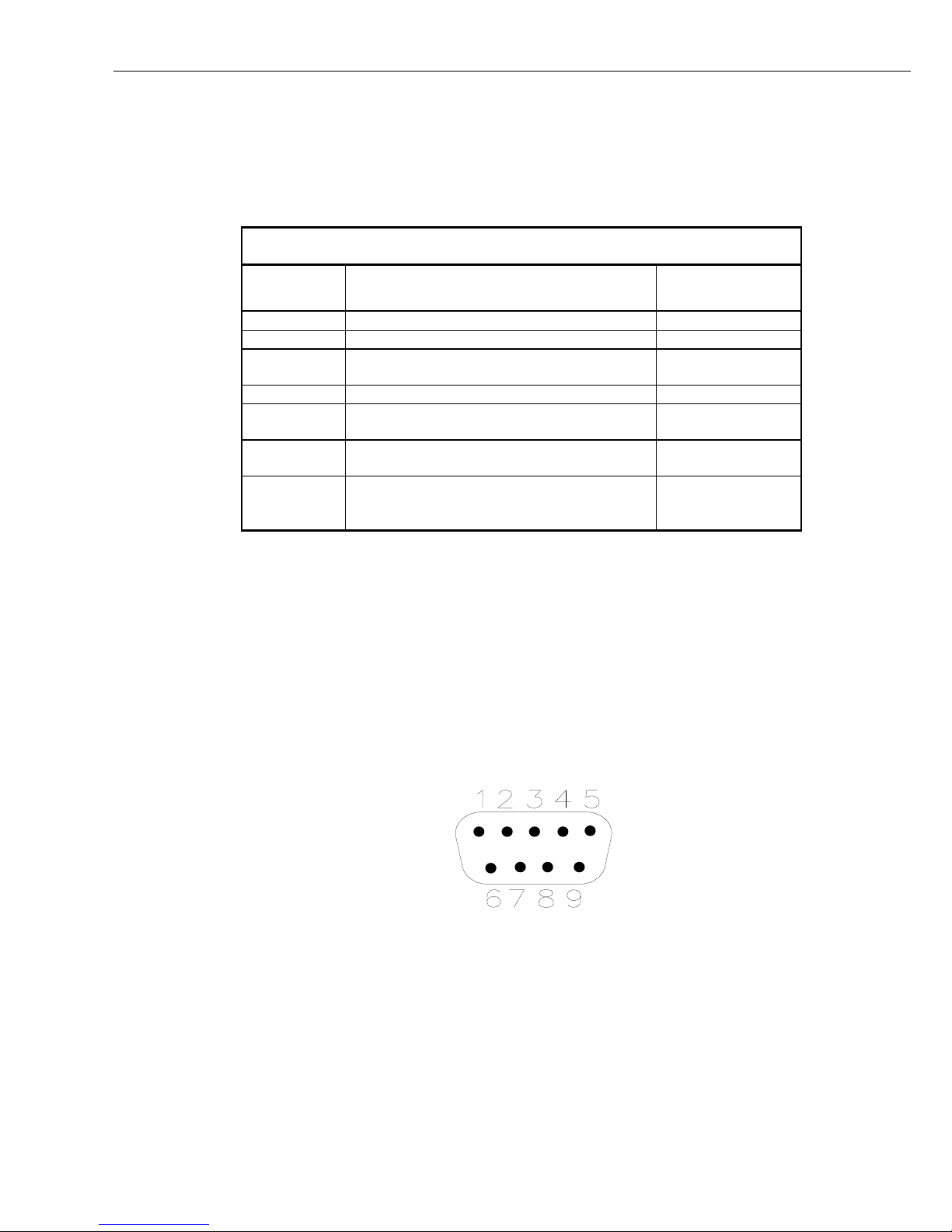
Datalogger Port
SERIAL I/O
Figure 2 Pin Positions for Datalogger Port: 9-way Male ‘D’ Type Connector
The datalogger port (marked ‘LOGGER’ in Figure 1) is a 9-way male ‘D’ type
connector, having the following pin configuration:
2
PIN ABBREVIATION I/O
1+5V
20V
3 RING O
Page 9

4RX O
5ME I
6SDE/PE I
7CLK/HS I
8 Connected to pin 8 of port B (12V supply)
9TX I
User Guide
NOTE
When the datalogger is in communication mode, pin 5
(ME – Modem Enable) is held high. This line is used by the
SDS-122 to detect communications and prevent switching to the
other port.
Switched Datalogger Port B
Figure 3 Pin Positions for Switched Datalogger Port ‘B’: 9-way Female ‘D’
The switched datalogger port (marked ‘PORT B’ in Figure 1) is a 9-way female
‘D’ type connector, having the following pin configuration:
SERIAL I/O
5 4 3 2 1
9 8 7 6
Type Connector
PIN ABBREVIATION I/O
1+5V
20V
3 RING I
4RX I
5ME O
6SDE/PE O
7CLK/HS O
8 Connected to pin 8 of the datalogger port (12V supply)
9TX O
3
Page 10

SDS-122 Serial Data Switch
25-Way Switched RS232 Port A
SERIAL I/O
13 1
25 14
Figure 4 Pin Positions for Switched RS232 Port ‘A’: 25-way Female ‘D’ Type
Connector
The 25-way switched RS232 port (marked ‘RS232 PORT A’ in Figure 1) is a
25-way female ‘D’ type connector, having the following pin configuration:
PIN ABBREVIATION INPUT/OUTPUT
DTE DCE
1 Frame Ground
2 TX O I
3 RX I O
4 RTS O I
5 CTS I O
6 DSR I O
7 GND
15 External Power Supply I I
20 DTR O I
Other pins are not connected.
Control Port (3-way Screw Terminal)
The control port is a 3-way terminal block with screwed connections. This
terminal block can be unplugged from the unit for ease of wiring. The terminal
connections are marked G, P and M and are used as follows:
TERMINAL CONNECTION
G 0V – It is recommended that a wire is run from this terminal
to the main protective earth point in the system to give
maximum protection from interference and transients.
P In MANUAL mode, this terminal can be pulled high to select
port B. In AUTO mode, when PL41 is fitted, it functions as an
output and will go logic high when port B is being used or logic
low when port A is being used.
4
M When this line is pulled high, the SDS-122 will be in MANUAL
mode and only the port that is selected by the user (by using the
P terminal) will be active.
Page 11

3. Installation
User Guide
You should install the SDS-122 in a dry, non-condensing environment. The
ENC12/14 datalogger enclosure, available from Campbell Scientific, provides an
ideal environment for, typically, a CR10/10X datalogger and the SDS-122, plus a
power supply or other equipment.
Use one SC12 cable to connect the SDS-122’s ‘datalogger’ port to a datalogger
port, and a second to connect port ‘B’ to a compatible modem. A computer/short
haul modem can be connected to port ‘A’ using a standard RS232 cable.
Normally, for most applications, there will be no need for a connection to be made
between the 3-way terminal block on the SDS-122 and the datalogger, unless
direct measurements of the switch status, or manual control is required. It is
recommended that a ground wire is connected between the ‘G’ terminal of the
SDS-122 and the system protective ground, to ensure optimum internal transient
protection of the device.
CAUTION
4. Configuration
CAUTION
Although the SDS-122 has built-in transient protection, it is not
protected against secondary lightning damage.
Devices that are connected to port A or port B which are likely
to be subject to large transients should have external
protection fitted. For long cable runs on port A, RAD-SRM
Short Haul modems fitted with RAD-SP lightning arrestors
should be used.
The configuration of the SDS-122 is defined by internal jumpers. To access these
jumpers it is necessary to open the case by removing the four case screws and
pulling the two halves of the case apart.
Before touching any components or jumpers, take precautions
against electrostatic damage when handling the exposed
circuit board – either by using an ESD protection earth strap
connected to the sensor case, or, at the very least, by making
sure that you discharge any static by touching the case or
metal shell of the 'D' type connectors on the circuit board.
The jumpers control:
• The way in which the SDS-122 switches from one port to another
• The RS232 port configuration (DCE or DTE)
• The degree of isolation between the datalogger and the RS232 device.
It is important to understand the different methods of isolation, as this can affect
the accuracy of measurements made by the datalogger. In permanent installations
it is good practise to ensure that the datalogger ground and computer ground are
isolated, otherwise ground loops and digital noise could result in errors on lowlevel analogue measurements. The SDS-122 can be set to provide opto-isolation
to prevent such ground loops, but this mode of operation is not suitable for all
RS232 devices, either because the device needs to source power from the
5
Page 12

SDS-122 Serial Data Switch
datalogger or because it is not able to provide power to the output electronics of
the SDS-122.
WARNING
The opto-isolation provided by the SDS-122 is not
designed, nor should it be used, for the purpose of
providing a safety protection barrier. Internal protection
devices will cause a breakdown of the isolation if the
potential difference between the datalogger and RS232
ground exceeds 47V.
To work in isolated mode, the RS232 device must provide power to the SDS-122
by holding at least one of the input handshaking lines at a positive voltage during
communications (pins 4 or 20 in DCE mode, pins 5 or 6 in DTE mode). The
voltage input to these lines must be <9V or be current limited to an effective
source impedance of 1Kohm. If a suitable handshaking line is not available, a
power source (6-20V) can be connected to pin 15 (referenced to pin 7G).
In non-isolated mode, the SDS-122 can provide power from the datalogger via the
handshaking lines, to power external interfaces. See details on jumpers PL50,
PL51 and PL56 below for information on the power available. When this mode is
enabled, no isolation is provided by the SDS-122. Some devices, such as the
RAD-SRM short haul modem, and most telephone modems provide their own
isolation barrier. Care should be taken when selecting third party devices to
ensure that they provide some form of barrier to prevent ground loops.
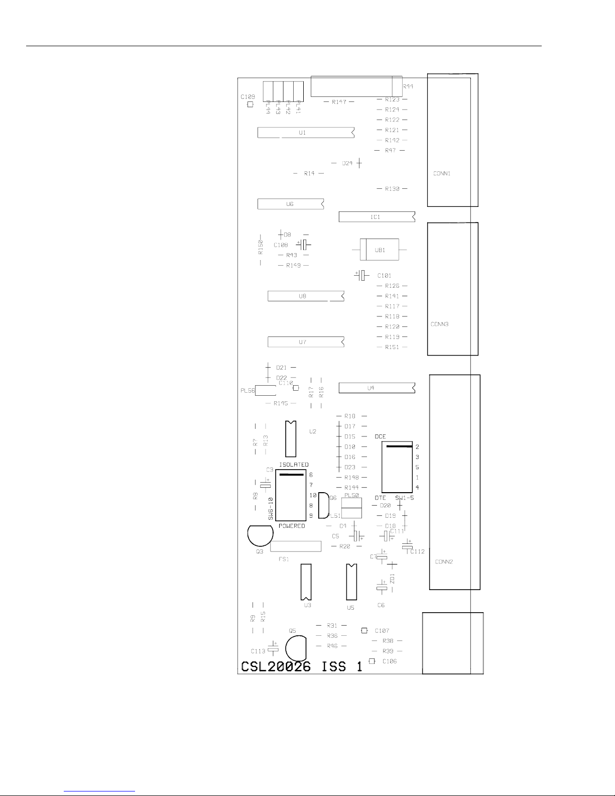
4.1 Jumper Configuration
It is envisaged that most applications will be with a telephone modem connected
to Port B and a personal computer connected directly to Port A. The SDS-122, as
supplied, has its jumpers set to this default configuration – please see Figure 5.
When used with a RAD-SRM modem on Port A in interactive mode, jumper
block SW6-10 and jumper PL50 must be changed from their default positions.
SW1-5 needs to be set to match the DTE/DCE setting of the RAD modem. If
using the default RAD setting (DCE), SW1-5 will need to be rotated – please refer
to Figure 6. The position of jumpers PL51 and PL56 may need to be reviewed if
outputtting data via Port A in ‘print-enabled’ mode.
The description of each jumper and its default setting is given in Section 4.3. Note
that some jumpers work in combination to achieve the state required.
4.2 Special Modes of Operation
The SDS-122 contains a programmable chip, which, in conjunction with the
jumper settings (see Section 4) determines the way in which the ports are selected.
Currently, the program allows one or other of the two communication ports to be
connected to the datalogger. There is no state where neither port is connected. For
special applications, the program can be modified to provide other modes of
operation. Please contact Campbell Scientific for more details.
6
Page 13
OPEN
OPEN
OPEN
User Guide
OPEN
OPEN
OPEN
OPEN
CONN 4
Figure 5 Default Jumper Positions on Circuit Board
7
Page 14

SDS-122 Serial Data Switch
OPEN
OPEN
OPEN
OPEN
OPEN
POWERED
TURN 180°
CHANGE TO DTE
TURN 180°
CHANGE TO
CLOSED
OPEN
Figure 6 Jumper Positions for a RAD-SRM Short Haul Modem on Port A
8
Page 15

4.3 Default Jumper Settings
JUMPER DEFAULT DESCRIPTION
PL41 Not fitted When jumper PL41 is fitted, port A/B
PL42 Not fitted When jumper PL42 is fitted the SDS-122 will
PL43 Not fitted This jumper works in combination with
User Guide
on the 3-way screw terminal will output
0V for switch on port A, or 5V for
switch on port B when the SDS-122 is in
AUTO mode only. When the jumper is not
fitted, or the unit is in MANUAL mode, then
the line becomes an input.
default to the port selected by PL43 when the
ME line goes low. When the jumper is not
fitted, the unit will stay with the last port
used after the ME line goes low.
jumper PL42. When jumper PL43 is fitted
and jumper PL42 is also fitted, the SDS-122
will revert to port B when the ME line goes
low. When PL43 is not fitted, but PL42 is
fitted, the unit will default to port A when the
ME line goes low.
PL44 Not fitted When jumper PL44 is fitted and synchronous
data is transmitted, (e.g. to a storage module),
the SDS-122 will block any data output to
port A. When PL44 is not fitted all data is
allowed to pass through to port A.
SW1-5 DCE Jumper block SW1-5 can be set so that port A
can operate as either a DCE or DTE interface,
and so there is no requirement for a null
modem cable. The ‘DCE’ and ‘DTE’ jumper
positions are marked on the PCB. Note that,
to change the settings, the whole jumper
block is removed and re-inserted at 180°. The
red line on the jumper block should be
adjacent to the state (DCE or DTE) required.
Port A should be set to be the opposite type
of interface to that to which it is being
connected; e.g. set Port A to DTE when
connecting to a RAD-SRM set to its default
DCE state.
SW6-10 Isolated Jumper block 6-10 can be set so that port A is
either optically isolated or powered. RADSRM short haul modems would be driven in
the powered mode. ‘Isolated’ and ‘Powered’
positions are marked on the PCB. Note that,
to change the settings, the whole jumper
block is removed and re-inserted at 180°. The
red line on the jumper block should be
adjacent to the state (Isolated or Powered)
required.
9
Page 16

SDS-122 Serial Data Switch
PL50 Not fitted When jumper PL50 is fitted, not less than
4.3V is supplied to pins 20 and 4 of port A in
DTE mode and to pins 5 and 6 of port A in
DCE mode. RAD-SRM modems in
interactive communications would need the
PL50 jumper to be fitted. The actual voltage
supplied to the pins will depend on the setting
of jumper PL51 (see below). When the
jumper is not fitted, no voltage is supplied.
This has no effect in isolated mode.
PL51 Not fitted When jumper PL51 is fitted, >7V is
permanently output to pins 20 and 4 of port A
in DTE mode and to pins 5 and 6 of port A in
DCE mode. This jumper is not normally fitted
for RAD-SRM modems in interactive
communication. When not fitted the outputs
are shut off when ME goes low.
PL56 Not fitted When jumper PL56 is fitted, >7V is supplied
to the handshake lines (pins 20 and 4 of port
A in DTE mode and pins 5 and 6 of port A in
DCE mode) when either ME or SDE/PE goes
high. When jumper PL56 is not fitted, 7V will
only be applied when ME is high. This has no
effect in isolated mode.
10
 Loading...