

Page 1
Overview
The PS200 and CH200 are charge controllers that manage amperage
and voltage for safe, optimized battery charging from a solar-panel
or ac power source. They also measure various input, output, and
status parameters to allow close monitoring of the battery during
COMPONENT
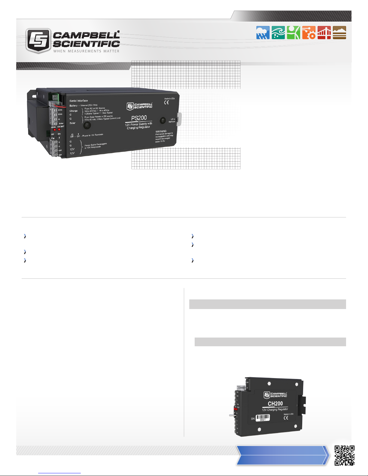
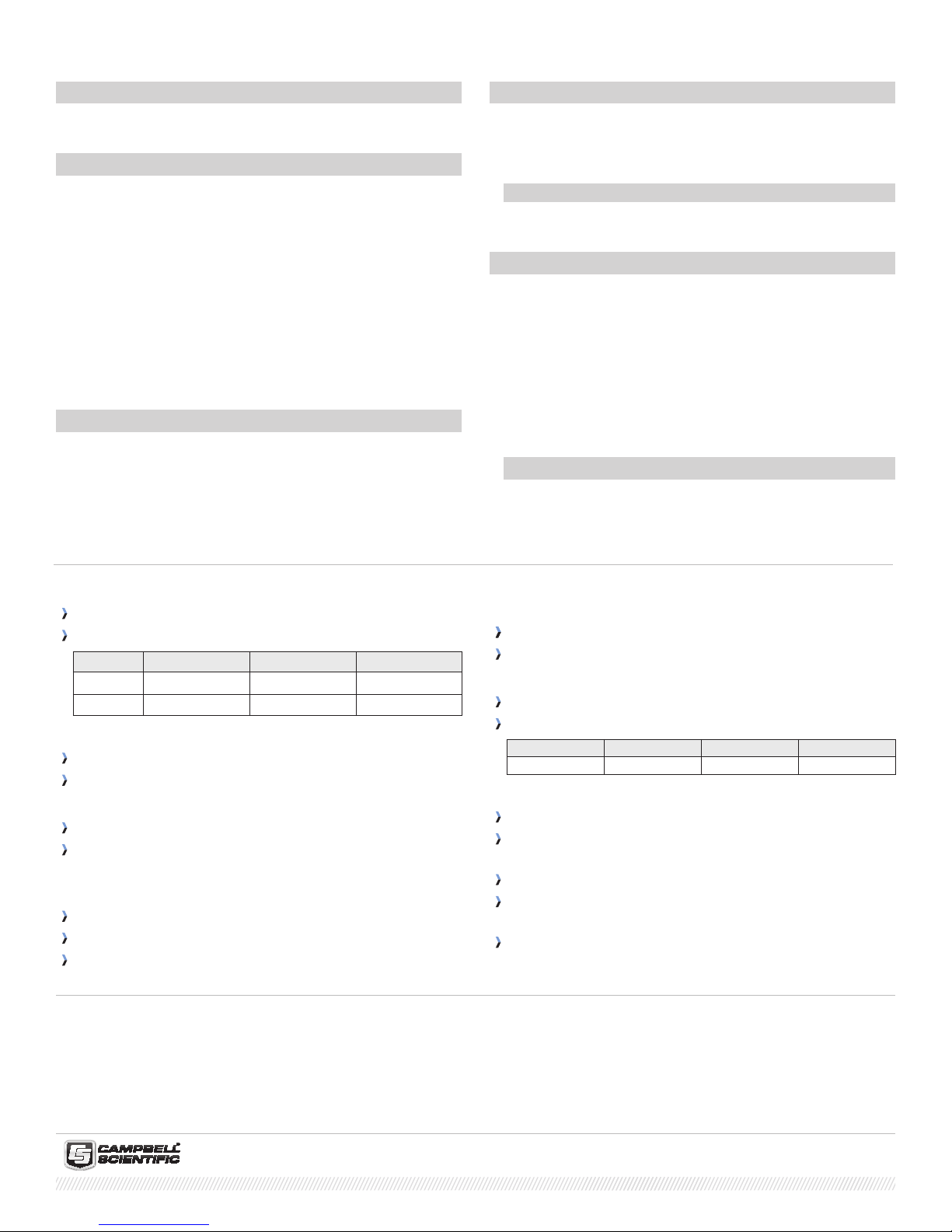
PS200 and CH200
Smart Power Supply and Charge Controller
Optimized Power
Performance
Manages voltage and
amperage to protect battery
charging and use. The PS200 includes a 12 Vdc valve-regulated leadacid (VRLA) battery, while the CH200 is for use with a separate larger
battery such as our BP12, BP24, or a user-supplied battery.
Benets and Features
Protects against high-amperage and high-voltage damage to
power supply
Ability to monitor both load and battery current
Real-time measurements of charge input voltage, battery voltage,
on-board temperature, battery current, and load current
Technical Description
The PS200 and CH200 are micro-controller-based smart chargers
with two-step constant voltage charging and temperature compensation that optimize battery charging and increase the battery’s life.
Two input terminals enable simultaneous connection of two charging sources. They also incorporate a maximum power point tracking
algorithm for solar inputs that maximize available solar charging
resources. RS-232 and SDI-12 terminals allow the PS200 and CH200
to convey charging parameters to a datalogger.
The PS200 and CH200 have several safety features intended to
protect the charging source, battery, charger, and load devices. Both
the SOLAR – G and CHARGE – CHARGE input terminals incorporate
hardware current limits and polarity-reversal protection. A fail-safe,
self-resettable thermal fuse protects the CHARGE – CHARGE inputs in
the event of a catastrophic AC/AC or AC/DC charging source failure.
Another self-resettable thermal fuse protects the 12 V output terminals of the charger in the event of an output load fault. The PS200
and CH200 also have battery-reversal protection, and include ESD
and surge protection on all of its inputs and outputs.
Battery reversal protection
Two-step constant voltage charging and temperature compensation optimize battery charging and increase the battery’s life
Allows simultaneous connection of two charging sources (e.g.,
solar panel, ac wall charger)
Ordering Information
Power Supplies
CH200 12 V Charging Regulator. Choose a warranty option (see below).
PS200 12 V Power Supply with Charging Regulator and 7 Ah Sealed
Rechargeable Battery. Choose a warranty option (see below).
Warranty Options (choose one)
-SW Standard 1 Year Warranty. See manual for full warranty policy.
-XW 4 Year Warranty Extension (available only at the time of
original product purchase).
More info: 435.227.9000
www.campbellsci.com/ps200
Page 2
Campbell Scientic, Inc. | 815 W 1800 N | Logan, UT 84321-1784 | (435) 227-9000 | www.campbellsci.com
USA | AUSTRALIA | BRAZIL | CANADA | CHINA | COSTA RICA | ENGLAND | FRANCE | GERMANY | SOUTH AFRICA | SPAIN
Ordering Information Continued
12 Vdc Battery Packs for CH200
BP12 12 Ah Sealed Rechargeable Battery with Mounts
BP24 24 Ah Sealed Rechargeable Battery with Mounts
Cables (interface and external battery)
20769 SDI-12 Interface Cable with a 2 ft length. Connects the power
supply’s SDI-12 terminal to the datalogger’s terminals, allowing
the datalogger to receive the power supply’s charging, load, battery voltage and current information.
25356 RS-232 Pigtail Interface Cable with a 2 ft length. Connects the
power supply’s RS-232 terminal to the datalogger’s terminals,
allowing the datalogger to receive the power supply’s charging,
load, battery voltage and current information.
20770 9-pin RS-232 Interface Cable with 6 ft length. Connects a PS200
or CH200 to a computer for changing its settings or downloading
a new operating system.
6186 Battery Cable for connecting a an external 12 Vdc ooded bat-
tery such as a deep-cycle marine or RV battery.
Adapters
Only one adapter can be used at a time.
A100 Null Modem Adapter for powering peripherals and external
devices at non-datalogger sites such as repeater stations.
A105 12 V Terminal Expansion Adapter that increases the number of
12 V and ground terminals available on the PS200 or CH200.
Wall Chargers
29796 Wall Charger 24 Vdc 1.67 A Output, 100 to 240 Vac, 1A Input,
5 ft Cable. Must choose a power plug option (see below).
22110 Wall Charger 24 Vdc 1.67 A Output, 100 to 240 Vac, 1A Input for
prewired enclosure. Must choose a power plug option (see below).
Power Plug Options (choose one)
-US US/Canada Plug
-IP 7 International Plugs
Unregulated Solar Panels
Regulated solar panels such as the SP10R are not recommended.
SP10 10 W Solar Panel with 20 ft cable
SP10-PW 10 W Solar Panel with 20 ft cable for prewired enclosure
SP20 20 W Solar Panel with 15 ft cable
SP20-PW 20 W Solar Panel with 15 ft cable for prewired enclosure
SP50-L 50 W Solar Panel with user-specied cable length (used with
the CH200 only). Enter length, in feet, after the -L. A 20 ft length
is typical; maximum length is 50 ft. Must choose a cable termination option (see below).
Cable Termination Options for the SP50-L (choose one)
-PT Cable terminates in stripped and tinned leads for connection
to the CH200.
-PW Cable terminates in a connector that attaches to a
prewired enclosure.
Specications
Operational Temperaturea: −40° to +60°C
Dimensions:
Height Length Width
PS200 10.6 cm (4.2 in) 19 cm (7.5 in) 7.6 cm (3 in)
CH200
10 cm (3.9 in) 7.5 cm (3 in) 3.7 cm (1.5 in)
CHARGE – CHARGE Terminals (AC or DC Source)
AC: 18 to 24 V RMS with 1.2 A RMS maximum
DC: 16 to 40 Vdc with 1.1 A DC maximum
SOLAR Terminals (Solar Panel or Other DC Source)b
Input Voltage Range: 15 to 40 Vdc
Maximum Charging Current: 3.6 Adc typical;
2.8 Adc to 4.3 Adc depending on individual charger)
Battery Chargingc
CYCLE Charging: Vbatt(T ) = 14.70 V − (24 mV) x (T − 25°C)
FLOAT Charging: Vbatt(T ) = 13.65 V − (18 mV) x (T − 25°C)
Accuracy: ±1% accuracy on charging voltage over -40° to +60°C
a
VRLA battery manufacturers state that “heat kills batteries” and recommend operating batteries ≤50°C.
b
Battery voltages below 8.7 V may result in <3.0 A current limit because of fold-back current limit.
c
Two-step temperature compensated constant-voltage charging for valve-regulated lead-acid batteries. Cycle and oat charging voltage parameters are
programmable with the default values listed.
d
Impulse type changes in current may have an average current error of ±(10% of reading + 2 mA).
e
1.0 V negative oset is worst-case due to reversal protection diode on input. Typical diode drop is 0.35 V.
f
2.0 V negative oset is worst-case due to two series diodes in AC full-bridge. Typical diode drops are 0.35 V each for 0.7 V total.
Quiescent Current
No Charge Source Present: 300 μA maximum
No Battery Connected: 2 mA maximum
Power Out (+12 terminals)
Voltage: Unregulated 12 V from battery
4 A Self-Resettable Thermal Fuse Hold Current Limits
<20°C 20°C 50°C 60°C
> 4 A 4.0 A 3.1 A 2.7 A
Measurements
Average Battery Voltage (-40° to +60°C): ±(1% of reading + 15 mV)
Average Battery/Load Current Regulator Input Voltage
(-40° to +60°C)d: ±(2% of reading +2 mA)
Solar (-40° to +60°C)e: ±(1% of reading − 0.25 V) / −(1% of reading + 1 V)
Continuous (-40° to +60°C)f:
±(1% of reading − 0.5 V) / − (1% of reading + 2 V)
Charger Temperature: ± 2°C
© 2011, 2013
Campbell Scientic, Inc.
May 15, 2014
 Loading...