

Page 1

PONDVIEW 4.0
CSI AQUACULTURE
AUTOMATED MONITORING AND CONTROL SUPPORT SOFTWARE
INSTRUCTION MANUAL
REVISION: 6/02
COPYRIGHT (c) 2000-2002 CAMPBELL SCIENTIFIC, INC.
Page 2

This is a blank page.
Page 3

Limited Warranty
CAMPBELL SCIENTIFIC, INC. warrants that the media on which the accompanying
computer software is recorded and the documentation provided with it are free from
physical defects in materials and workmanship under normal use. CAMPBELL
SCIENTIFIC, INC. warrants that the computer software itself will perform substantially
in accordance with the specifications set forth in the Operator’s Manual published by
CAMPBELL SCIENTIFIC, INC. CAMPBELL SCIENTIFIC, INC. warrants that the
software is compatible with Windows 2000, Windows NT 4.0 Service Pack 4 or
greater. CAMPBELL SCIENTIFIC, INC. is not responsible for incompatibility of this
software running under any operating system other than those specified in
accompanying data sheets or Operator’s Manuals.
The above warranties are made for ninety (90) days from the date of original shipment.
CAMPBELL SCIENTIFIC, INC. will replace any media or documentation which
proves defective in materials or workmanship without charge.
CAMPBELL SCIENTIFIC, INC. will either replace or correct any software that does
not perform substantially according to the specifications set forth in the Operator’s
Manual with a corrected copy of the software or corrective code. In the case of
significant error in the documentation, CAMPBELL SCIENTIFIC, INC. will correct
errors in the documentation without charge by providing addenda or substitute pages.
If CAMPBELL SCIENTIFIC, INC. is unable to replace defective documentation or
media, or if CAMPBELL SCIENTIFIC, INC. is unable to provide corrected software or
corrected documentation within a reasonable time, CAMPBELL SCIENTIFIC, INC.
will either replace the software with a functionally similar program or refund the
purchase price paid for the software.
CAMPBELL SCIENTIFIC, INC. does not warrant that the software will meet
licensee’s requirements or that the software or documentation are error free or that the
operation of the software will be uninterrupted. The warranty does not cover any media
or documentation which has been damaged or abused. The software warranty does not
cover any software which has been altered or changed in any way by anyone other than
CAMPBELL SCIENTIFIC, INC. CAMPBELL SCIENTIFIC, INC. is not responsible
for problems caused by computer hardware, computer operating systems or the use of
CAMPBELL SCIENTIFIC, INC.’s software with non-CAMPBELL SCIENTIFIC,
INC. software.
ALL WARRANTIES OF MERCHANTABILITY AND FITNESS FOR A
PARTICULAR PURPOSE ARE DISCLAIMED AND EXCLUDED. CAMPBELL
SCIENTIFIC, INC. SHALL NOT IN ANY CASE BE LIABLE FOR SPECIAL,
INCIDENTAL, CONSEQUENTIAL, INDIRECT, OR OTHER SIMILAR DAMAGES
EVEN IF CAMPBELL SCIENTIFIC HAS BEEN ADVISED OF THE POSSIBILITY
OF SUCH DAMAGES.
CAMPBELL SCIENTIFIC, INC. is not responsible for any costs incurred as result of
lost profits or revenue, loss of use of the software, loss of data, cost of re-creating lost
data, the cost of any substitute program, claims by any party other than licensee, or for
other similar costs.
LICENSEE’S SOLE AND EXCLUSIVE REMEDY IS SET FORTH IN THIS
LIMITED WARRANTY. CAMPBELL SCIENTIFIC, INC.’S AGGREGATE
LIABILITY ARISING FROM OR RELATING TO THIS AGREEMENT OR THE
SOFTWARE OR DOCUMENTATION (REGARDLESS OF THE FORM OF
ACTION; E.G., CONTRACT, TORT, COMPUTER MALPRACTICE, FRAUD
AND/OR OTHERWISE) IS LIMITED TO THE PURCHASE PRICE PAID BY THE
LICENSEE.
Page 4

License for Use
This software is protected by both the United States copyright law and
international copyright treaty provisions. You may copy it onto a computer to
be used and you may make archival copies of the software for the sole purpose
of backing-up CAMPBELL SCIENTIFIC, INC. software and protecting your
investment from loss. All copyright notices and labeling must be left intact.
This software may be used by any number of people, and may be freely moved
from one computer location to another, so long as there is not a possibility of it
being used at one location while it’s being used at another. The software,
under the terms of this license, cannot be used by two different people in two
different places at the same time.
815 W. 1800 N.
Logan, UT 84321-1784
USA
Phone (435) 753-2342
FAX (435) 750-9540
www.campbellsci.com
Campbell Scientific Canada Corp.
11564 -149th Street
Edmonton, Alberta T5M 1W7
CANADA
Phone (780) 454-2505
FAX (780) 454-2655
Campbell Scientific Ltd.
Campbell Park
80 Hathern Road
Shepshed, Loughborough
LE12 9GX, U.K.
Phone +44 (0) 1509 601141
FAX +44 (0) 1509 601091
Page 5

PondView Table of Contents
PondView Introduction
I.1 Please Read This........................................................................................1
I.2 Overview ...................................................................................................1
I.3 Installation.................................................................................................1
I.4 Uninstall ....................................................................................................3
I.5 Some Notes on System Resources.............................................................3
....................................................1
1. Setting Up the Network and Communicating
1.1 Getting Started ...................................................................................... 1-1
1.2 Setup ..................................................................................................... 1-1
1.2.1 Start the Server............................................................................ 1-1
1.2.2 Configure Communication.......................................................... 1-2
1.3 Device Configuration Settings.............................................................. 1-4
1.3.1 Serial Port.................................................................................... 1-4
1.3.2 PakBusPort.................................................................................. 1-4
1.3.3 CR10X-TD.................................................................................. 1-4
2. PondView Display Screen
2.1 Enable the Display................................................................................ 2-1
2.2 Overview Page...................................................................................... 2-1
2.3 Pond Page ............................................................................................. 2-2
2.4 Temperature Thermometer ................................................................... 2-3
2.5 Trends ................................................................................................... 2-3
.......................................2-1
........1-1
3. Control Set Points and Alarms
3.1 Control Set Points ................................................................................. 3-1
3.1.1 Aerator Control ........................................................................... 3-1
3.2 Alarms .................................................................................................. 3-2
3.2.1 Aerator Alarms............................................................................ 3-2
3.2.2 Dissolved Oxygen Alarm............................................................ 3-3
3.2.3 Communication Alarm................................................................ 3-3
4. Manual Control
4.1 Aerator Control..................................................................................... 4-1
5. Timer Aerator Control
6. DO Probe Calibration
6.1 Dissolved Oxygen Calibration.............................................................. 6-1
6.2 Air Calibration ...................................................................................... 6-1
6.3 Hand Calibration................................................................................... 6-1
.........................................................4-1
..............................................5-1
...............................................6-1
i
...............................3-1
Page 6

PondView Table of Contents
7. Communication Status
8. Remote Buoy
8.1 Wireless Dissolved Oxygen Probe........................................................ 8-1
8.2 Buoy Parameters ................................................................................... 8-1
9. Troubleshooting
........................................................... 8-1
...................................................... 9-1
........................................... 7-1
ii
Page 7

PondView Introduction
I.1 Please Read This
Welcome to PondView, Campbell Scientific’s Windows compatible support
software for CR10X-TD Monitoring and Control Systems. Please take time to
read this manual thoroughly before installing your software. We have
designed PondView to be as intuitive as possible, so have intentionally kept
this manual short.
This manual assumes that the user is familiar with the Microsoft Windows
interface. If you need help with some of Windows’ features, please call a
Campbell Scientific Applications Engineer.
I.2 Overview
PondView is a combination of two separate software programs that interface
together to provide complete monitoring and control support of your
Automated Monitoring and Control System via the personal computer.
Initial setup will be supported through LoggerNet, while regular monitoring
and control will be a function of the PondView screen.
I.3 Installation
For most applications LoggerNet will be used very infrequently; however, it
will always be running in the background. For some modifications and
troubleshooting LoggerNet may be required.
As with all software, Campbell Scientific strongly recommends that a back-up
of critical files be performed before software installation. In addition, periodic
back-ups should be performed on files in the Campbellsci directory.
PondView requires Windows NT, Windows 2000 or Windows XP operating
systems. The computer should have at least a Pentium II processor with 128
MB RAM.
The following instructions assume that drive D: is a CD-ROM drive on the
computer from which the software is being installed. If the drive letter is
different, substitute the appropriate drive letter.
Install the LoggerNet CD by inserting the CD into the CD slot of the computer;
this will initiate the installation process. DO NOT change the default locations
for the directories and file locations. Follow this installation by installing the
PondView CD. As with the LoggerNet CD, this will automatically initiate the
installation process. DO NOT change the default locations for directories and
file locations. Simply select Next.
1
Page 8
PondView Introduction
If remote PCs are being used to network with the main server computer, then
PondView is the only installation that is required. Installation of LoggerNet is
only required on the server PC.
When prompted to restart the computer select Yes. If insertion of the CD does
not initiate the installation process, proceed as follows: From the Windows
system menu, select Start | Run.
Type D:\Setup.exe in the Open field or use the Browse button to access the
CD-ROM drive and select the setup executable in the folder.
This activates the PondView Installation Utility. Follow the prompts on the
screen to complete the installation.
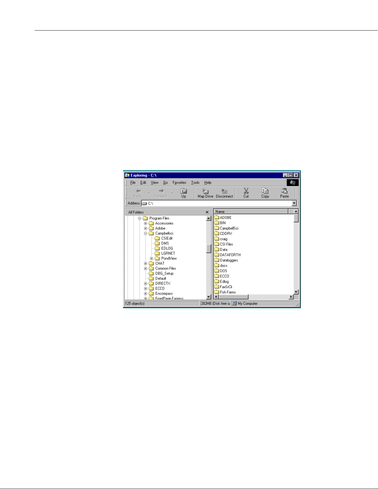
The file Campbellsci will be loaded into the C:\Program Files directory. All
of the LoggerNet and PondView files will be found in the Campbellsci file.
Each PondView software package also includes a customized Application File.
This program is found on the 3 ½ floppy disk.
To install this file, insert the floppy disk into your A: drive. Using Windows
Explorer select the A: drive. Click the right mouse button and select Copy on
PondView.ini. Paste this file to the C:/Program File/Campbellsci/PondView
folder. This file already exists in the PondView folder so you will be asked if
you would like to replace it. Select yes. This will load the proper files to
operate your individualized program.
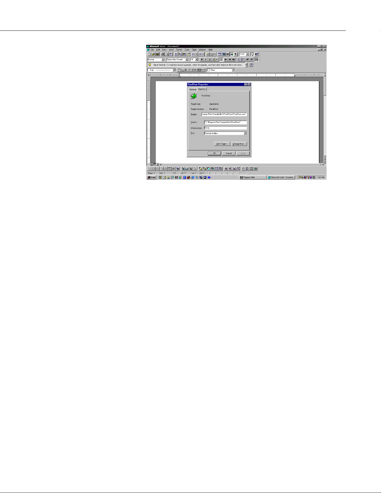
If a remote PC is used to network with the server running LoggerNet, the
network path needs to be specified as part of the PondView path.
Right click on PondView, found in START | PROGRAMS. A menu will
appear. Select Properties.
2
Page 9
PondView Introduction
The Path should read: “C:\Program Files\Campbellsci\PondView\
PondView.exe” 192.168.22.131 username password 6789
The 192.168.22.131 is the IP address of the server computer. This will be
different for every computer.
If a username or password is not used, then any word can be substituted.
I.4 Uninstall
Should you need to remove PondView from a computer, an uninstall program
is provided. Select SETTINGS from the Start button then select CONTROL
PANEL. Double click on ADD/REMOVE programs. Select PondView from
the list and select the Add/Remove button.
I.5 Some Notes on System Resources
PondView is capable of running in the background while you are doing other
work with other programs. To do this, it uses the system’s idle time for some
of its serial communications. Some other applications may be so resource
intensive that PondView does not receive sufficient time for its
communication. PondView will not run reliably with these applications
loaded.
3
Page 10

PondView Introduction
This is a blank page.
4
Page 11
Section 1. Setting Up the Network and Communicating
1.1 Getting Started
With the software installed, you are probably anxious to start using PondView.
If at all possible, prior to deploying the equipment in the field, make sure you
can establish a telecommunication link with the CR10X-TD—even if you have
to create a temporary setup in your office. Getting familiar with PondView
and your CR10X-TD in the comfort of your office will be a lot less frustrating
than trying to resolve problems in the field. If your CR10X-TD is already
deployed and working, then establishing communications with the CR10X-TD
is the place to start. RF radio telecommunication should not be operated at
close distances. Damage to your radios can occur.
1.2 Setup
The LoggerNet communications server is the application that provides the
software interface between the computer applications and the CR10X-TD
network. The server software must be running on the computer for data
monitoring and control to occur and to allow any of the applications to be
used to access information from the CR10X-TD.
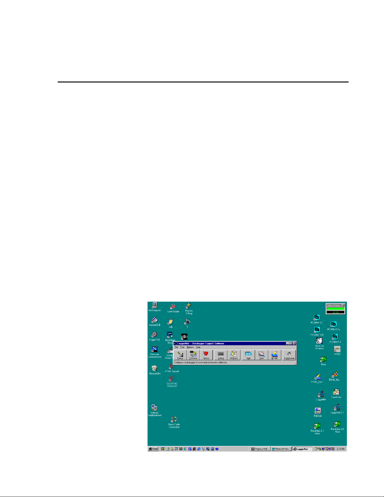
1.2.1 Start the Server
The Server is accessed through the PROGRAMS directory. From the Start
button select PROGRAMS. From the PROGRAMS menu select LoggerNet.
A bar menu will be displayed.
1-1
Page 12
Section 1. Setting Up the Network and Communicating
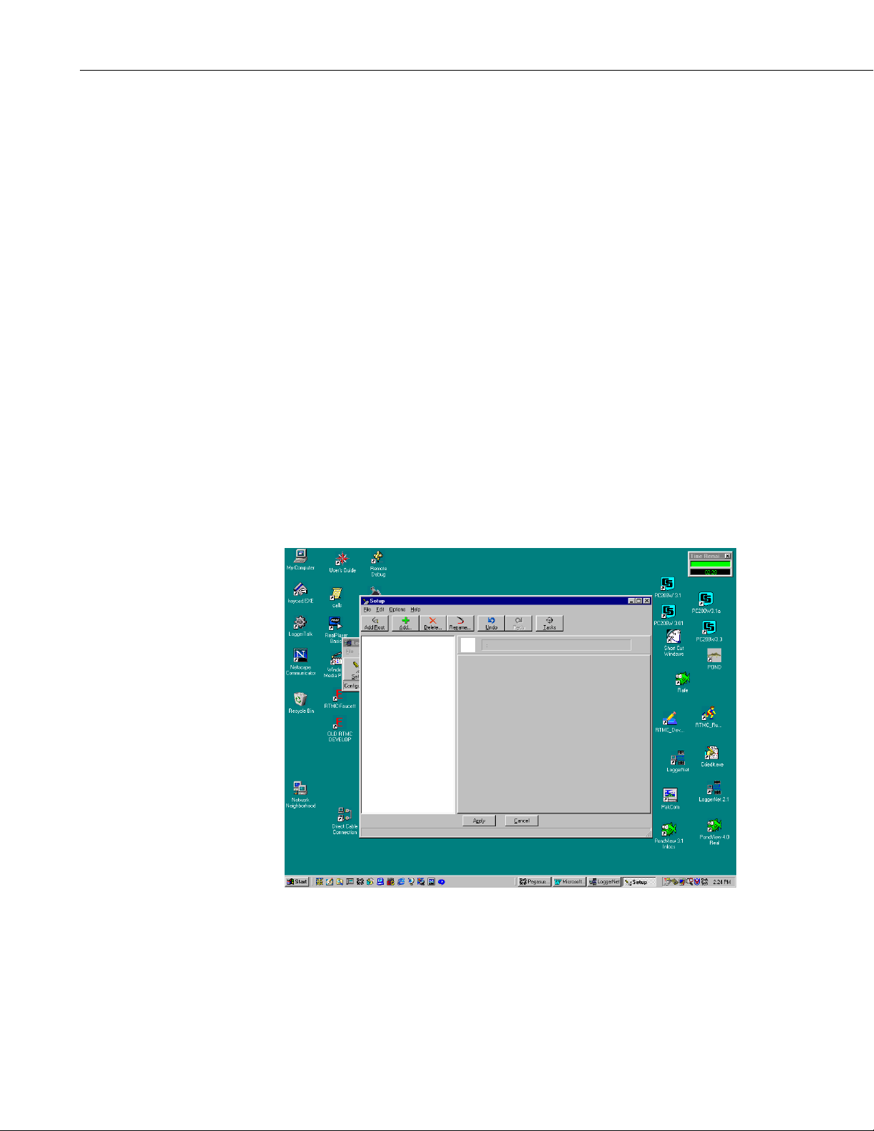
1.2.2 Configure Communication
The Setup Screen is used to configure your CR10X-TD network, define the
communication link that exists between the computer and the CR10X-TD, and
to set up the data collection schedule.
Although many different methods are used for communication between the
monitoring system and the PC, the following are the most common methods
used.
• Direct Connect - Simple serial communication or RAD Short-Haul
Modem communication.
• Spread Spectrum Radio - Connection using Campbell Scientific RF400 or
other spread spectrum radios. These radios do not require FCC licenses.
Distance for communication is limited.
• Radio Frequency (RF) - Connection over specific frequencies require an
FCC license. Distances are generally greater than for the RF400 although
both require line-of-site paths.
The Setup Screen is accessed through the LoggerNet Menu Bar. The Setup
button is the first button from the left of the Menu Bar.
When you first select the Setup button, the dialog box should appear as:
The Setup Screen is divided into two parts: the device map (left side of the
screen) and the set up tabs (right side of the screen).
1-2
Begin adding devices to the device map in the order that they appear in your
communication link. For example, let’s assume your CR10X-TD is connected
to the computer via an RF400 radio link. You would first add a Serial Port,
Page 13

Section 1. Setting Up the Network and Communicating
then the PakBusPort, then the CR10X-PB, this is the path of communication
from the PC to the CR10X-PB.
A new device can be added to the network device map by choosing Edit | Add
from the Setup menu. The Add Device Window will appear.
When you select an item from the left side of the Add Device window, valid
connections will be displayed in the right-hand column. Highlight the item to
which you want to attach the device and select the Add Now button. Continue
to add devices in this manner until your network map is complete.
For direct connection to the CR10X using short RS232 connection, RAD Short
Haul Modems, or RF400 Spread Spectrum Radio the device map would be:
1-3
Page 14

Section 1. Setting Up the Network and Communicating
Once all devices are added to the device map, complete the forms associated
with each device. Refer to the sections that immediately follow for
information on setting up devices. The CR10X-PB is a default label and must
be edited. The PondView Software will be looking for a label called
CR10XTD_1. After all settings are configured, apply the Setup program by
selecting the Apply button; this saves all settings.
1.3 Device Configuration Settings
When you highlight any device on the network shown on the left side of the
Setup screen, forms appear on the right side with the relevant settings. These
settings are different for different devices and are described in detail below.
1.3.1 Serial Port
The serial port has only a Hardware tab to configure.
Communication Enable - Before communication can take place, all devices in
the communications chain must be enabled. The default setting for this check
box is Enabled.
Call-Back Enable - Leave unchecked.
Com Port Connection - This field designates the communications port through
which you will be connecting to the CR10X-TD or RF232T Base Station.
Select the arrow to the right of the field with a mouse to display Com 1
through Com 8. For most computers Com 1 will be used.
Extra Response Time - Leave this set at the default rate. Additional time may
be needed in instances where the communications link is noisy or network
traffic is heavy.
1.3.2 PakBusPort
Communication Enabled - Must be checked.
PakBus Port is Dialed - Leave unchecked.
Extra Response Time - Leave default value of 000s.
Beacon Interval - Leave default value of 060s.
1.3.3 CR10X-TD
The CR10X-TD has four different tabs. Similar to a serial port, a hardware tab
is completed to specify communication settings. There are also tabs to define
the method of data collection, how often data should be collected, and whether
to automatically update the CR10X-TD’s clock.
1-4
Page 15

1.3.3.1 Hardware Tab
Communication Enable - Before communications can take place, all devices in
the chain must be enabled.
Maximum Time On-Line - Set to 5 min.
Maximum Packet Size - Default 2048 bytes should be used.
Extra Response Time - Default 0 ms should be used.
Maximum Baud Rate - Default of 9600.
Security Code - The CR10X-TD can have a security code to restrict access to
the system. This helps prevent inadvertent changes to the CR10X-TD’s
program or memory. Leave this value set to 0. If a security code is needed,
the CR10X-TD program must also be changed.
PakBus Address - This must correspond with the value set in the CR10X.
Default is 1. Each logger in the network must have individual numbers.
Section 1. Setting Up the Network and Communicating
1.3.3.2 Data Collection Tab
The data collection tab is used to define what data tables will be copied from
the CR10X-TD. The tables available will not be shown until Scheduled
Collection has been enabled. Skip to the 1.3.2.3 Scheduled Collection Tab
before Data Collection Tab. Tables selected and checked with the green check
mark should only include REAL and HIST. All other tables should be marked
with the red X, excluding them from the Tables section.
All other parameters should be left as the default value.
1-5
Page 16

Section 1. Setting Up the Network and Communicating
1.3.3.3 Scheduled Collection Tab
The Scheduled Collection tab defines when PondView will automatically
collect data from the CR10X-TD.
Scheduled Collection Enabled - This check box activates the data collection
schedule defined on this tab. This box must be checked.
Initial Date - Leave as default date.
Initial Time - Set this 10 seconds after the hour. This allows all wireless
probes to respond to the CR10X before data collection begins.
Collection Interval - This is the interval at which the CR10X-TD will be
queried for new data. If this interval is set at 10 minutes, new data will be
collected from the CR10X-TD every 10 minutes. One minute is generally
quick enough for most data collection. Longer times or shorter times may be
set depending upon how frequently data must be updated.
Primary Retry Interval- If a data collection attempt is made but fails, you can
specify an interval on which another attempt will be made. The Primary Retry
Interval should always be greater than the Collection Interval.
Number of Primary Retries - The number entered into this field is the number
of times PondView will attempt to contact the CR10X-TD on the Primary
Retry Interval. If the number of collection attempts specified are unsuccessful,
then the server will revert to calling on the Secondary Retry Interval.
Secondary Retry Interval - The Secondary Retry Interval is a calling interval
that will be attempted if all Primary Retries have failed. The Connection
Status Screen Alarm on the PondView screen will be activated if the
Secondary Retry Interval is reached. Data collection attempts will continue on
the Secondary Interval until a data collection attempt is successful, at which
time all retry statistics are reset.
1-6
Page 17

1.3.3.4 Clock Check/Set Tab
Automated Clock Check - Enable this to compare the CR10X-TD clock to the
server computer’s clock based on the schedule defined by the other parameters
on this tab. If the CR10X-TD’s time differs from the PC time by more than a
specified amount, the CR10X-TD clock will be set automatically. Enable
should be checked. Set the clock initial time to 15 seconds after the hour. All
other settings should be left at the default value.
Section 1. Setting Up the Network and Communicating
1-7
Page 18

Section 1. Setting Up the Network and Communicating
This is a blank page.
1-8
Page 19

Section 2. PondView Display Screen
2.1 Enable the Display
PondView is activated by selecting Start|Programs|PondView.
When PondView is first started, please be patient. The initialization may take
a few minutes.
2.2 Overview Page
The Overview Page provides a quick summary of the dissolved oxygen
readings in each pond. Ponds are arranged in sections corresponding to the
stations that monitor the pond. Each station group includes a time stamp of
when the data was collected.
In addition to the dissolved oxygen value, an alarm light is displayed along the
right side of each DO value. If the alarm condition occurs, the light will be
red; if the alarm is not active, then the light will be green.
A smaller light will be displayed along the left side of the pond label. This
alarm light represents communication of the remote buoy to the monitoring
station. A green light indicates successful communication between the buoy
and monitoring station. A red light indicates communication has been lost.
2-1
Page 20

Section 2. PondView Display Screen
2.3 Pond Page
The Pond Page provides a desktop display for real-time dissolved oxygen and
motor amps, and is used for entering set points for alarms, control of aeration,
and sensor calibration.
2-2
Page 21

2.4 Temperature Thermometer
The temperature thermometer can be use to monitor temperature in degrees
Fahrenheit or Celsius. Using the mouse, click on the thermometer the degree
units will change to either Celsius or Fahrenheit.
2.5 Trends
Seven days of historical data is displayed on the Trends Graph. Select the
Trends Graph by using the mouse left button to open the Trends Button
A specific value with time stamp can be viewed by selecting the data point on
the graph with the mouse arrow, then clicking the left mouse button. The
selected value will be displayed in the upper right hand corner of the graph.
The associated time stamp will be displayed in the upper left hand corner of the
graph.
The graph can be sent to a printer by clicking the graph icon in the upper right
corner of the graph.
Section 2. PondView Display Screen
.
This is only a sample of the data that is being collected and stored by the
CR10X-TD. If more data is needed, the PondView Graph can be customized
for specific application, or call a Campbell Scientific, Inc. Applications
Engineer for help.
2-3
Page 22

Section 2. PondView Display Screen
This is a blank page.
2-4
Page 23

Section 3. Control Set Points and Alarms
3.1 Control Set Points
3.1.1 Aerator Control
The CR10X-TD automatically controls each aerator. If the dissolved oxygen
in the pond is below a user-determined value, then the aerator is switched on.
If the dissolved oxygen raises to a high set point, the aerator is switched off.
Double-click on the pond label (example Pond 1). This will pull up a slider
switch that is used to set the low and high points for each aerator in Pond 1.
The set point can be changed in two ways. To use the slider bar, point the
mouse arrow to the colored bar on the slider. While holding the left button on
the mouse slide the bar up to the value desired.
Use the edit box by highlighting the value to be changed and enter the new
value. This value will not be sent to the CR10X-TD until the ENTER key on
the PC keypad is pushed.
The aerator will switch on when the DO value is less than the value selected
with the DO ON slider. The aerator will switch off when the DO value is equal
to or greater than the value selected with the DO OFF slider. When changing
this value, the bar to show the status by turning black temporarily. At this
point the value has been sent to the CR10X-TD and the slider box can be
closed (select the X in the upper right corner).
3-1
Page 24

Section 3. Control Set Points and Alarms
3.2 Alarms
PondView provides audio and visual alarms to indicate when critical levels
have been reached. These alarms indicate critical levels of dissolved oxygen,
aerator motor amps, and communication.
To acknowledge the alarm, point to the visual alarm with the mouse and push
the right mouse button. An ALARM ACKNOWLEDGE button will appear.
Select this button and the audio alarm will be deactivated. Alarms will switch
off if the alarm condition on longer exists.
3.2.1 Aerator Alarms
Aerator status is being monitored by the CR10X-TD. Aerator alarms can be
activated on two conditions. If the aerator is supposed to be on but if the amps
being monitored indicate a value that is lower than expected, the amp alarm
will be activated. Also, if the amps being drawn are higher than is expected,
the alarm will be activated.
The high set point will also disable the aerator if the condition is met. For
example, if the amps high set point on aerator 1 in pond 1 is set at 40 amps,
and the amps being monitored indicate 41 amps, then the alarm will be
activated and the aerator will be switched off.
These two set points are selected by clicking with the mouse on the aerator that
is desired. Alarms have both a visual display and an audio sound. They are
activated every 30 seconds.
3-2
Page 25

3.2.2 Dissolved Oxygen Alarm
To select the slider bars for DO alarm set points, double click on the CLICK
FOR ALARMS SET POINT box found in the lower right corner. Like the
other slider bars, move the bar until the desired set point is found. This enables
the alarms for the dissolved oxygen in the ponds. If the DO is lower than the
set point, the alarms are activated. These alarms are acknowledged by using
the mouse to select the alarm and pressing the right mouse key.
Section 3. Control Set Points and Alarms
3.2.3 Communication Alarm
If communication between the CR10X-TD and PC is disrupted, the
Communication Status light will turn red and alarm sounds are activated.
Disable this alarm by selecting the acknowledge button.
3-3
Page 26

Section 3. Control Set Points and Alarms
This is a blank page.
3-4
Page 27

Section 4. Manual Control
The automated feature of the CR10X-TD can be overridden using the
PondView monitor. Switching aerators on or off can also be accomplished
using the on-screen display.
4.1 Aerator Control
Click the desired aerator with a right mouse. The Control button will be
displayed. Selecting turn on will override the automated conditions of aerator
control and turn the aerator on.
To switch off aerators that have been switched on, click the desired aerator
with the right mouse button. The Control button will be displayed. Selecting
Turn Off will return control of the aerator back to the automated function
controlled by the CR10X-TD. The aerator will turn off if the High-Off SetPoint for that aerator is less than the current dissolved oxygen reading.
4-1
Page 28

Section 4. Manual Control
This is a blank page.
4-2
Page 29

Section 5. Timer Aerator Control
In addition to the aerators being controlled automatically be the condition of
the dissolved oxygen, and manually by the operator, they can also be
controlled by a timer.
Like the manual mode of control, the time mode of control overrides the
automated control based on the condition of the dissolved oxygen. The timers
will turn the aerator on and off at a user specified time regardless of the
condition of the dissolved oxygen.
Click on the desired aerator. Click on the Timer Status button; this will pop up
the Paddle Wheel Timer Select screen. In this screen enter the desired start and
stop times. These must be entered in military times. After a value is entered in
the Set Start Time and Set Stop Time locations, the corresponding button must
be pressed in order to send these values to the CR10X-TD.
Even with the start and stop values sent to the CR10X-TD, the timer function is
not active until the Timer Status Button is turned ON. To turn the button on,
click the Timer Status button with the right mouse. Select ON. The timer is
now active and will control the aerators based on the times entered.
5-1
Page 30

Section 5. Timer Aerator Control
This is a blank page.
5-2
Page 31

Section 6. DO Probe Calibration
6.1 Dissolved Oxygen Calibration
The CR10X-TD is programmed to allow for both automatic dissolved oxygen
air calibration and automatic hand calibration of the dissolved oxygen probes.
Use whichever method is best for your application.
6.2 Air Calibration
Before the air calibration process is enabled the dissolved oxygen probes and
temperature sensor must be removed from the water. Since sunlight can
greatly heat these probes, which will adversely effect the accuracy of the
calibrated value, this process is best performed when the sun is clouded or at
dusk or dawn.
Once the probes are out of the water use the right mouse button to select the
calibration mode. An on/off button will be displayed. Click the button with
the mouse. The line will change on the Calibration Knob to indicate the
calibration status. Give the probes 10 to 15 minutes to stabilize before setting
the calibration process off. The Calibration status should be in the off position
for normal operations.
6.3 Hand Calibration
Hand calibration allows calibrating the submersed dissolved oxygen probe to a
value obtained using an accurate hand-held dissolved oxygen meter. Click on
the Hand Calibration button. Edit the box corresponding to the DO probe that
6-1
Page 32

Section 6. DO Probe Calibration
is to be calibrated. Enter the value obtained using the hand dissolved oxygen
meter. Press the Enter key on the PC keypad to send this new value to the
CR10X-TD. Once all of the corrected values have been entered into the edit
boxes, click the calibration status button with the right mouse. Select Turn On.
The CR10X-TD will remain in the Hand Calibration mode for 30 seconds,
after which it will automatically return to the Normal operation mode.
6-2
Page 33

Section 7. Communication Status
Communication Status (Status Monitor) provides a way to monitor
communication statistics for the CR10X-TD network. Information can be
viewed on data collection attempts and communication failures. This program
is especially useful when using RF communication.
From the LoggerNet Tool Bar button select STATUS.
Status Monitor is customized to display only those columns containing
communication data of interest. To add columns to the Status Monitor
window, select Edit | Select Columns. The Column Modifications window
appears.
Entries in the Statistics Not Visible field will not be displayed on the main
Status Monitor screen. Entries in the Statistics Visible field will be displayed
on the screen.
7-1
Page 34

Section 7. Communication Status
This is a blank page.
7-2
Page 35

Section 8. Remote Buoy
8.1 Wireless Dissolved Oxygen Probe
PondView provides data to view the current conditions of the wireless
dissolved oxygen probe. The Buoy is only displayed on your screen if you are
using the wireless system.
8.2 Buoy Parameters
Use the mouse and right click on the yellow buoy to view the critical
parameters of the wireless probe.
8-1
Page 36

Section 8. Remote Buoy
This is a blank page.
8-2
Page 37

Section 9. Troubleshooting
Problem Solution
PondView Screen does not represent
my pond lay out.
The program on the CR10X-TD has
been changed and now the PondView
Screen will not communicate.
PondView is shipped with a
standard .INI file that represents a
generic pond lay out. You must
replace this generic lay out with one
that has been created for your farm.
This file is found on the 3-1/2” disk
shipped with your equipment.
The server is looking for a specific
list of labels found on the CR10XTD. If the program has been
modified this list may have been
changed. To ensure the server is
looking for the current labels go the
START button on the computer.
Select Programs|LoggerNet|Control
Panel. Select the appropriate station.
Select Options|Advanced|Update
Table Definitions.
9-1
Page 38

Section 9. Troubleshooting
This is a blank page.
9-2
 Loading...