

Page 1

INSTRUCTION MANUAL
MetData1 Weather Station
with CM6/CM10 Tripod
Revision: 4/98
Copyright (c) 1993-1998
Campbell Scientific, Inc.
Page 2

Warranty and Assistance
The METDATA1 AND THE CM6/CM10 TRIPOD are warranted by
CAMPBELL SCIENTIFIC, INC. to be free from defects in materials and
workmanship under normal use and service for twelve (12) months from date
of shipment unless specified otherwise. Batteries have no warranty.
CAMPBELL SCIENTIFIC, INC.'s obligation under this warranty is limited to
repairing or replacing (at CAMPBELL SCIENTIFIC, INC.'s option) defective
products. The customer shall assume all costs of removing, reinstalling, and
shipping defective products to CAMPBELL SCIENTIFIC, INC. CAMPBELL
SCIENTIFIC, INC. will return such products by surface carrier prepaid. This
warranty shall not apply to any CAMPBELL SCIENTIFIC, INC. products
which have been subjected to modification, misuse, neglect, accidents of
nature, or shipping damage. This warranty is in lieu of all other warranties,
expressed or implied, including warranties of merchantability or fitness for a
particular purpose. CAMPBELL SCIENTIFIC, INC. is not liable for special,
indirect, incidental, or consequential damages.
Products may not be returned without prior authorization. The following
contact information is for US and International customers residing in countries
served by Campbell Scientific, Inc. directly. Affiliate companies handle
repairs for customers within their territories. Please visit
www.campbellsci.com to determine which Campbell Scientific company
serves your country. To obtain a Returned Materials Authorization (RMA),
contact CAMPBELL SCIENTIFIC, INC., phone (435) 753-2342. After an
applications engineer determines the nature of the problem, an RMA number
will be issued. Please write this number clearly on the outside of the shipping
container. CAMPBELL SCIENTIFIC's shipping address is:
CAMPBELL SCIENTIFIC, INC.
RMA#_____
815 West 1800 North
Logan, Utah 84321-1784
CAMPBELL SCIENTIFIC, INC. does not accept collect calls.
Page 3

TABLE OF CONTENTS
PDF viewers note: These page numbers refer to the printed version of this document. Use
the Adobe Acrobat® bookmarks tab for links to specific sections.
PAGE
1. PREPARATION AND SITING............................................................................................ 1-1
1.1 Installation Tasks ...................................................................................................................1-1
1.2 Tools Required....................................................................................................................... 1-1
1.3 Siting and Exposure............................................................................................................... 1-3
1.4 Determining True North for Wind Vane Orientation............................................................... 1-5
2. TOWER/TRIPOD INSTALLATION................................................................................... 2-1
2.1 Tower/Tripod Installation
2.2 Sensor Mounting Brackets
3. INSTRUMENTATION INSTALLATION........................................................................... 3-1
3.1 Enclosure, Datalogger, and Power Supply
3.2 Sensor Connection
3.3 Communication and Data Storage Peripherals
3.4 Sealing and Desiccating the Enclosure
4. SENSOR INSTALLATION .................................................................................................. 4-1
4.1 034A Met One Windset..........................................................................................................4-1
4.2 014A Met One Wind Speed Sensor....................................................................................... 4-1
4.3 024A Met One Wind Direction Sensor...................................................................................4-2
4.4 05103 and 05305 RM Young Wind Monitors......................................................................... 4-2
4.5 03001 RM Young Wind Sentry Wind Set............................................................................... 4-3
4.6 03101 RM Young Wind Sentry Anemometer ........................................................................ 4-3
4.7 LI200S Li-Cor Silicon Pyranometer/LI190SB Quantum Sensor............................................ 4-4
4.8 107/108 Temperature Probe.................................................................................................. 4-4
4.9 107B Soil Temperature Probe ............................................................................................... 4-5
4.10 CS500 Vaisala Temperature and RH Probe ......................................................................... 4-5
4.11 HMP35C Vaisala Temperature and RH Probe...................................................................... 4-6
4.12 CS105 Vaisala Barometric Pressure Sensor......................................................................... 4-6
4.13 TE525 Texas Electronics Tipping Bucket Rain Gage............................................................ 4-7
4.14 CS700-L Rain Gage............................................................................................................... 4-7
4.15 SR50 Sonic Ranging Sensor................................................................................................. 4-8
4.16 CS615-L Water Content Reflectometer................................................................................. 4-8
4.17 237 Leaf Wetness Sensor ..................................................................................................... 4-9
4.18 257 Soil Moisture Sensor.......................................................................................................4-9
4.19 Wind Direction Sensor Orientation ...................................................................................... 4-10
5. SOFTWARE INSTALLATION............................................................................................ 5-1
6. MAINTENANCE AND TROUBLESHOOTING .............................................................. 6-1
6.1 Maintenance .......................................................................................................................... 6-1
6.2 Troubleshooting..................................................................................................................... 6-2
I
Page 4

TABLE OF CONTENTS
LIST OF TABLES
3.3-1 Station ID Numbers and Corresponding Switch Settings**................................................. 3-10
3.3-2 Station ID Numbers and Corresponding Switch Settings.................................................... 3-12
LIST OF FIGURES
2.1-1 CM10 Weather Station........................................................................................................... 2-1
2.1-2 Extending the Tripod Legs..................................................................................................... 2-1
2.1-3 Tripod and Component Orientation ....................................................................................... 2-2
2.1-4 Ground Rod and Clamp......................................................................................................... 2-2
2.1-5 Tripod Ground Clamp ............................................................................................................ 2-3
2.2-1 019ALU Crossarm and Lightning Rod................................................................................... 2-4
2.2-2 Gill Radiation Shield............................................................................................................... 2-4
2.2-3 015 Pyranometer Mounting Arm............................................................................................ 2-4
2.2-4 025 Pyranometer Crossarm Stand........................................................................................2-4
3.1-1 MetData1 Enclosure on CM6 or CM10 Tripod ...................................................................... 3-2
3.1-2 MetData1 Enclosure on UT10 or UT30 Tower ...................................................................... 3-2
3.1-3 PS12LA/CH12R Wiring and Switch Panel.............................................................................3-3
3.1-4 BPALK 12 in MetData1 Enclosure......................................................................................... 3-3
3.1-5 PS12LA in MetData1 Enclosure ............................................................................................ 3-3
3.1-6 MSX10 Solar Panel on CM6 or CM10 Tripod........................................................................ 3-4
3.1-7 MSX10 Solar Panel on UT10 or UT30 Tower........................................................................ 3-4
3.2-1 Illustration of MetData1
External bottom panel showing sensor, communication, power, and ground connections... 3-5
3.2-2 MetData1 Jumper Configuration............................................................................................ 3-5
3.3-1 SM192/SM716 Storage Module............................................................................................. 3-6
3.3-2 Telephone Modem Installation............................................................................................... 3-7
3.3-3 Phone Installation .................................................................................................................. 3-7
3.3-4 SRM-5A and SC932 at Datalogger........................................................................................ 3-8
3.3-5 SRM-5A Wiring ...................................................................................................................... 3-9
3.3-6 RF95 RF Modem and RF100/RF200 Transceiver............................................................... 3-10
3.3-7 RF232 Base Station Installation........................................................................................... 3-11
3.3-8 MD9 Multidrop Interface in MetData1.................................................................................. 3-12
3.3-9 MD9 Multidrop Interface at the Computer and at the MetData1.......................................... 3-13
3.4-1 Inside MetData1 Lid............................................................................................................. 3-13
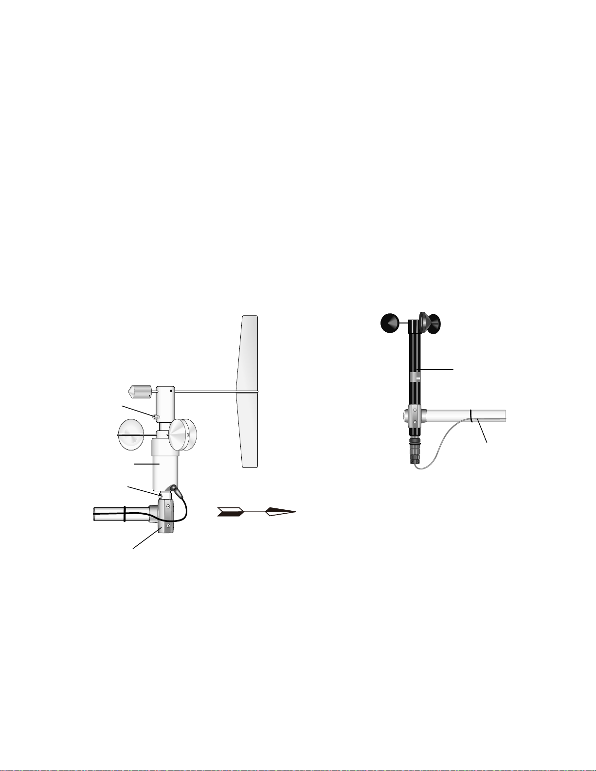
4.1-1 Met One 034A Wind Speed and Direction Sensor................................................................ 4-1
4.2-1 Met One 014A Wind Speed Sensor....................................................................................... 4-1
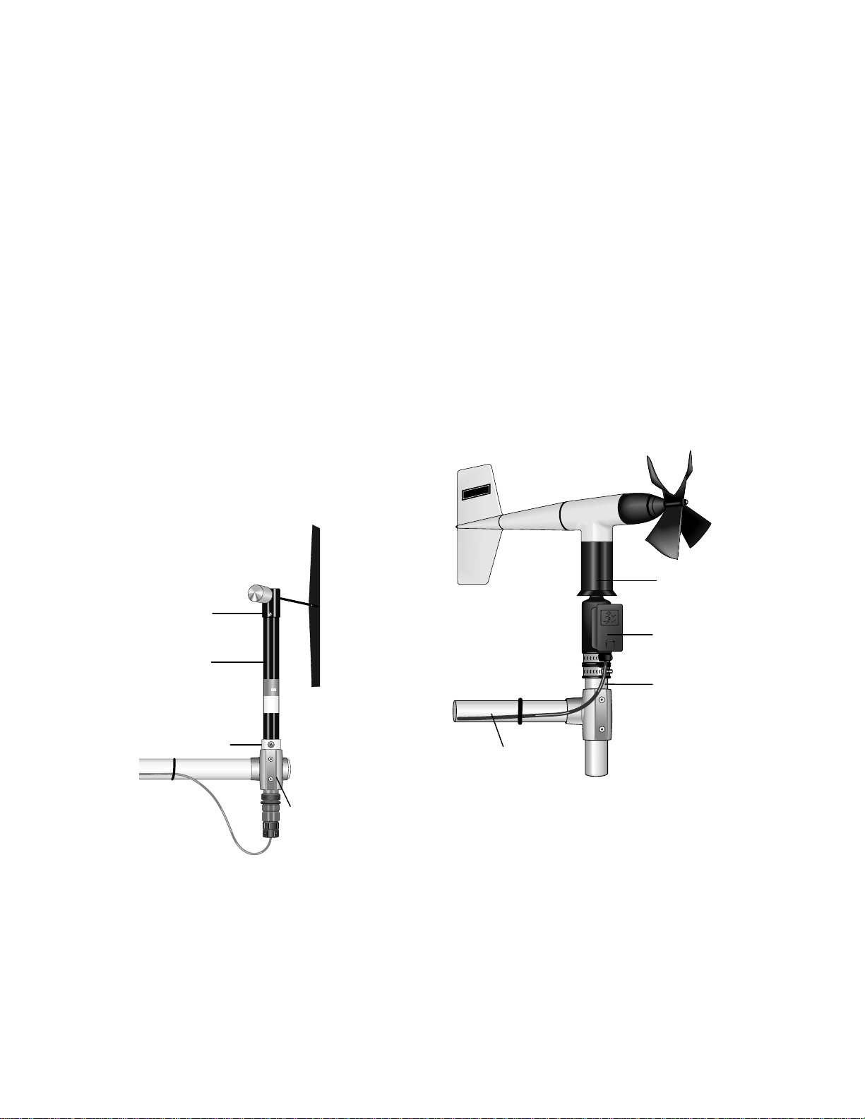
4.3-1 Met One 024A Wind Direction Sensor................................................................................... 4-2
4.4-1 05103 RM Young Wind Monitor............................................................................................. 4-2
4.5-1 03001 Mounted to the Mast................................................................................................... 4-3
4.5-2 03001 Mounted to 019ALU Crossarm................................................................................... 4-3
4.6-1 03101 RM Young Wind Sentry Anemometer......................................................................... 4-3
4.7-1 LI200S/LI190SB and LI2003S Leveling Fixture..................................................................... 4-4
4.8-1 107 Temperature Probe.........................................................................................................4-4
4.10-1 CS500 Temperature and RH Probe ...................................................................................... 4-5
4.11-1 HMP35C Vaisala Temperature and RH Probe...................................................................... 4-6
4.12-1 CS105 Vaisala Barometric Pressure Sensor in a Custom Weather Station Enclosure........ 4-6
4.12-2 CS105MD Vaisala Barometric Pressure Sensor in a MetData1 Enclosure .......................... 4-6
4.13-1 TE525 Texas Electronics Rain Gage..................................................................................... 4-7
4.14-1 CS700-L Rain Gage and CM100 Mounting Bracket.............................................................. 4-7
4.15-1 SR50 Sonic Ranging Sensor................................................................................................. 4-8
4.16-1 CS615 Water Content Reflectometer with CS615G Probe Insertion Guide ......................... 4-8
4.17-1 237 Leaf Wetness Sensor...................................................................................................... 4-9
4.18-1 257 Soil Moisture Sensor....................................................................................................... 4-9
4.19-1 Magnetic Declination for the Contiguous United States...................................................... 4-10
4.19-2 Declination Angles East of True North Are Subtracted From 0 to Get True North..............4-11
4.19-3 Declination Angles West of True North Are Added to 0 to Get True North......................... 4-11
II
Page 5

SECTION 1. PREPARATION AND SITING
These guidelines apply to several different Campbell Scientific weather stations.
1.1 INSTALLATION TASKS
1.1.1 INDOORS
• Immediately upon receipt of your
shipment…
⇒ Open shipping cartons.
⇒ Check contents against invoice.
Contact CSI immediately about any
shortages.
• Several days prior to the planned
installation date…
⇒ Collect tools and site information
(Section 1)
⇒ Assemble datalogger, communications
device, and power supply in enclosure
(Section 3)
⇒ Install datalogger support software on
PC (Section 5)
⇒ Install instrumentation enclosure
(Section 3)
⇒ Install sensors (Section 4)
• UT30 (10 meter tower) tower stations:
⇒ Install 3 to 10 meter level sensors
(Section 4)
⇒ Raise tower (Section 2)
⇒ Install instrumentation enclosure
(Section 3)
⇒ Install 0 to 3 meter level sensors
(Section 4)
• ET101 / ET106 ET Stations:
⇒ Place instrumentation enclosure low on
the ET Tower (Section 3)
⇒ Install sensor option (Section 4)
⇒ Establish communications between the
datalogger and the PC (Section 5)
⇒ Program datalogger, test sensors, and
retrieve data (Section 5)
⇒ Trial run the tower / tripod installation,
assembling as much as possible
(Section 2)
⇒ Repackage equipment for transport to
the field site
1.1.2 OUTDOORS
• Locate suitable site (Section 1)
• Prepare tower or tripod base (Section 2)
• Tripod and UT10 (3 meter tower) tower
stations:
⇒ Raise tripod or tower (Section 2)
⇒ Slide enclosure to top of tower and
secure with correct orientation (Section 3)
1.2 TOOLS REQUIRED
Tools required to install and maintain a weather
station are listed below.
1.2.1 TOOLS FOR TOWER INSTALLATION All Towers
Shovel
Rake
Open end wrenches: 3/8", 7/16", ½",
(2) 9/16"
Magnetic compass
6' Step ladder
CM6/CM10
Tape measure (12')
Level (12" to 24")
Small sledge hammer
Teflon tape or pipe dope
Allen hex wrench (5/64)
1-1
Page 6

SECTION 1. PREPARATION AND SITING
UT10
Tape measure (12' to 20')
Level (24" to 36")
Pick or digging bar
Claw Hammer
Materials for concrete form:
Hand saw
(4) 12" wood stakes
(1) 2"x 4"x 8' piece of lumber
(8) 8p double-head nails
(8) 16p double-head nails
Concrete trowels
(2) 1 to 1.5" thick x 24" boards
to support base above
forms (optional)
Concrete (0.4 cubic yards)
ET Tower
Tape measure (12’ to 20’)
Claw hammer
Level (24” to 36”)
Hand saw
Materials for concrete form:
(4) 1" x 2" x 12" stakes
(2) 2" x 4" x 96" lumber
(12) 8p double-head nails
(8) 16p double-head nails
20 ft form wire
½ Yard concrete
Concrete trowel, edger
Electrical Fish tape or 20 feet of
small diameter rope
Wheelbarrow
UT30
Tape measure (12' and 20')
Nut driver (3/8")
Level (36" to 48")
Small sledge hammer
Pliers
Tie wire
Climbing harness
Hard hat
Haul rope (50')
Non-stretch line (20')
Wire rope cutters
Materials for B18 Base and UTEYE Anchors:
(4) Wood stakes 12"
Pick or digging bar
Concrete form materials (2"x 4"
lumber, stakes, saw,
hammer, nails, etc.)
Concrete trowel and edger
Materials for UTDUK Duckbill Anchors
Sledgehammer
Highlift jack
Chain (to attach jack to anchor
loops)
Materials for RFM18 Base:
(3) anchors appropriate for
mounting surface
(3) bolts and washers to secure
base to anchors
1.2.2 TOOLS FOR INSTRUMENTATION AND MAINTENANCE
All Towers
Lock and key for enclosure
Magnetic declination angle (Section 4)
Magnetic compass
Straight bit screwdrivers (small,
medium, large)
Phillips-head screwdrivers (small,
medium)
Small diagonal side-cuts
Needle-nose pliers
Wire strippers
Pocket knife
Calculator
Volt / Ohm Meter
Electrical Tape
Step ladder (6')
Datalogger prompt sheet (Section 6)
Station manuals
Station log and pen
Open end wrenches: 3/8", 7/16", ½", (2)
9/16"
Socket wrench and 7/16" deep well
socket
Adjustable wrench
Pliers
Conduit and associated tools (as
required)
Felt-tipped marking pen
Claw hammer
Pipe wrench (12")
CM6/CM10
Tape measure (12')
Level (12" to 24")
Teflon tape or pipe dope
UT10
Tape measure (12' to 20')
3/8" nut driver
Level (24" to 36")
Teflon tape or pipe dope
(12) ¼" washers (for the 015 Crossarm
stand only)
Allen wrench set
1-2
Page 7

SECTION 1. PREPARATION AND SITING
UT30
Tape measure (12' to 20')
3/8" nut driver
Level (36" to 48")
Pliers
Climbing harness
Hard hats
50' haul rope
Crescent wrench
Channel-lock pliers
¼" washers (spacers for U-bolts)
5/64" Allen hex wrench
1.2.3 SUPPLIES FOR POWER AND COMMUNICATIONS OPTIONS
AC Power
Wire, conduit, and junction boxes as
needed
Phone Modem
Hayes compatible calling modem for PC
Phone line to weather station or
junction box
Short-Haul Modem
4 Conductor communications cable
from PC to weather station or
junction box
6' copper ground rod and clamp for PC
surge protection (optional)
1.3 SITING AND EXPOSURE
CAUTION: If any part of the weather
station comes in contact with power lines,
you could be killed. Contact local utilities
for the location of buried utility lines before
digging or driving ground rods.
Selecting an appropriate site for the weather
station is critical in order to obtain accurate
meteorological data. In general, the site should
be representative of the general area of interest,
and away from the influence of obstructions
such as buildings and trees.
The weather station should not be located
where sprinkler irrigation water will strike
sensors or instrument enclosure.
1.3.1 WIND SPEED AND DIRECTION
Wind sensors should be located over open level
terrain, and at a distance of at least ten times
(EPA) the height of any nearby building, tree or
other obstruction, as illustrated in Figure 1.3-1.
Standard measurement heights:
3.0 m ± 0.1 m recommended (AASC)
2.0 m ± 0.1 m, 10.0 m ± 0.5 m optional (AASC)
10.0 m (WMO and EPA)
1.3.2 TEMPERATURE AND RELATIVE HUMIDITY
Sensors should be located over an open level
area at least 9 m (EPA) in diameter. The
surface should be covered by short grass, or
where grass does not grow, the natural earth
surface. Sensors should be located at a
distance of at least four times the height of any
nearby obstruction and at least 30 m (EPA)
from large paved areas. Sensors should be
protected from thermal radiation, and
adequately ventilated.
Situations to avoid include:
• large industrial heat sources
• rooftops
• steep slopes
• sheltered hollows
• high vegetation
• shaded areas
• swamps
• areas where snow drifts occur
• low places holding standing water after
rains
Standard measurement heights:
1.5 m ± 1.0 m (AASC)
1.25 - 2.0 m (WMO)
2.0 m temperature (EPA)
2.0 m and 10.0 m for temperature difference
(EPA)
1.3.3 PRECIPITATION
A rain gage should be sited on level ground that
is covered with short grass or gravel. In open
areas, the distance to obstructions should be
two to four times (EPA, AASC) the height of the
obstruction.
Some general guidelines for site selection are
listed below, which were condensed from EPA
(1988)
1
, WMO (1983)2, and AASC (1985)
3
publications.
The height of the opening should be as low as
possible, but should be high enough to avoid
splashing from the ground. Wind shields, such
as those used by the National Weather Service,
are recommended for open areas.
1-3
Page 8

SECTION 1. PREPARATION AND SITING
Collectors should be heated, if necessary, to
properly measure frozen precipitation. The
gage must be mounted above the average level
of snow accumulation in areas that experience
significant snowfall.
Standard measurement heights:
1.0 m ± 1.0 cm (AASC)
30.0 cm minimum (WMO, EPA)
1.3.4 SOLAR RADIATION
Pyranometers should be located to avoid
shadows on the sensor at any time. Mounting it
on the southern most (northern hemisphere)
portion of the weather station will minimize the
chance of shading from other weather station
structures. Reflective surfaces and sources of
artificial radiation should be avoided. The height
at which the sensor is mounted is not critical.
1.3.5 SOIL TEMPERATURE
The measurement site for soil temperature should
2
be at least 1 m
and typical of the surface of
interest. The ground surface should be level with
respect to the immediate area (10 m radius).
Standard measurement depths:
10.0 cm ± 1.0 cm (AASC)
5.0 cm, 10.0 cm, 50.0 cm, 100.0 cm (WMO)
H
Height of tree (T)
REGCOMENDED
FeedSENSORS
27115
Serial
PortlandOr USA
REGCOMENDED
FeedSENSORS
Serial2711527115
PortlandOr USA
REGCOMENDED
FeedSENSORS
Serial
27115
PortlandOr USA
10H
10T
FIGURE 1.3-1. Effect of Structure on Wind Flow
1-4
Page 9
SECTION 1. PREPARATION AND SITING
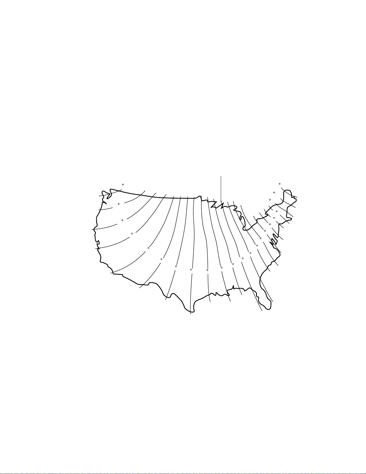
1.4 DETERMINING TRUE NORTH FOR WIND VANE ORIENTATION
Magnetic declination, or other methods to find True
North, should be determined prior to installing the
weather station. True North is usually found by
reading a magnetic compass and applying the
correction for magnetic declination*; where
magnetic declination is the number of degrees
between True North and Magnetic North. Magnetic
declination for a specific site can be obtained from a
USFA map, local airport, or through an internet
service called NSSDC CGM (Section 1.4.1). A
general map showing magnetic declination for the
contiguous United States is shown in Figure 1.4-1.
Subtract declination from 360° Add declination to 0°
22 E
20 E
18 E
16 E
14 E
12 E
10 E
Declination angles east of True North are
considered negative, and are subtracted from 0
degrees to get True North as shown Figure 1.4-2.
Declination angles west of True North are considered positive, and are added to 0 degrees to get
True North as shown in Figure 1.4-3. For
example, the declination for Logan, Utah is 14.5°
East. True North is 360° - 14.5°, or 345.5° as read
on a compass.
* Other methods employ observations using
the North Star or the sun, and are
discussed in the Quality Assurance
Handbook for Air Pollution Measurement
Systems, Volume IV - Meteorological
4
.
20 W
18 W
16 W
14 W
12 W
10 W
8 W
6 W
4 W
2 W
0
8 E
Measurements
4 E
6 E
2 E
FIGURE 1.4-1. Magnetic Declination for the Contiguous United States
1-5
Page 10

SECTION 1. PREPARATION AND SITING
1.4.1 NSSDC CGM SERVICE
The NSSDC CGM (Corrected Geomagnetic)
Service provides an easy way of determining
magnetic declination of a specific site. Since
magnetic declination fluctuates with time, it
should be determined each time the wind vane
orientation is adjusted. It can be accessed on
the world wide web at
http://nssdc.gsfc.nasa.gov/space/cgm/cgm.html
If you know the latitude and longitude of your
site, fill out Form 1as shown below for an
accurate magnetic declination. If you do not
know the latitude and longitude of your site, fill
out Form 2 for estimate of magnetic declination.
Note that longitude is expressed in 0 to 360
degrees east of the Greenwich prime meridian,
and that north latitudes are positive.
Geographic Alt. CGM IGRF Magnetic Field Dipole
Lat. Long. (km) Lat. Long. H(nT) D(deg) Z(nt) Lat. Long.
Query Form 1: Latitude/Longitude
Latitude/Longitude below specified in:
Geographic
Year (from 1945 to 2000): 1998
Altitude above Earth's surface (km) [from 0.
to 40000.]: 0
Latitude (degrees) [from -90.00 to 90.00]:
42.03
Longitude (degrees) [from 0.00 to 360.00]:
248.15
Query Form 2: Image Map
Year (from 1945 to 2000): 1998
Altitude above Earth's surface (km)
[0. - 40000.]: 0
Click on map to specify location and submit:
(select area on map provided)
A table containing similar information to the
following will be returned after submitting Forms
1 or 2.
42.03 248.15 0. 49.80 311.06 20608. 14.417 50505. 49.68 312.14
1-6
Page 11

SECTION 1. PREPARATION AND SITING
Magnetic declination is bold in this example to
show its location in the table. A positive
declination is east, while a negative declination
is west. The declination in this example is
14.417 degrees. As shown in Figure 1.4-1, the
declination for Logan, UT is east, so True North
for this site is 360 - 14.417, or 345.5 degrees.
FIGURE 1.4-2. Declination Angles East of
True North Are Subtracted From 0 to Get
True North
References
1
EPA, (1987). On-Site Meteorological Program
Guidance for Regulatory Modeling Applications,
EPA-450/4-87-013. Office of Air Quality
Planning and Standards, Research Triangle
Park, North Carolina 27711.
2
WMO, (1983). Guide to Meteorological
Instruments and Methods of Observation.
World Meteorological Organization No. 8, 5th
edition, Geneva, Switzerland.
3
The State Climatologist, (1985) Publication of
the American Association of State
Climatologists: Height and Exposure Standards
for Sensors on Automated Weather Stations,
v. 9, No. 4 October, 1985.
4
EPA, (1989). Quality Assurance Handbook for
Air Pollution Measurement Systems, EPA Office
of Research and Development, Research
Triangle Park, North Carolina 27711.
FIGURE 1.4-3. Declination Angles West of True
North Are Added to 0 to Get
True North
1-7
Page 12

Page 13

SECTION 2. CM6/CM10 TRIPOD INSTALLATION
The CM6 and CM10 tripods provide a support structure for mounting weather station components.
Figure 2-1 shows a typical guyed CM10 tripod weather station equipped with instrumentation enclosure,
meteorological sensors, and solar panel.
FIGURE 2-1. CM10 Weather Station
2-1
Page 14

SECTION 2. TRIPOD INSTALLATION
2.1 SPECIFICATIONS
CM6 Tripod
Maximum height
(zero leg extension) 7.5 feet
Minimum height
(full leg extension) 5.5 feet
Wind Load (Wind Sensors at 2 meters)*
Maximum wind load 100 mph
Gust survival 130 mph
Tripod Leg Diameter (See Table 1-5)
d = diameter
h = height at top of bell reducer
d = 2 (4.834 + (54.5
CM10 Tripod
Maximum height
(zero leg extension) 11 feet
Minimum height
(full leg extension) 7.2 feet
Wind Load (Wind Sensors at 3 meters)*
No Guy Wires
Maximum 70 mph
Gust survival 100 mph
With Guy Wires
Maximum 120 mph
Gust survival 150 mph
Tripod Leg Diameter (See Table 1-6)
d = diameter
h = height at top of bell reducer
d = 2 (4.834 + (78.75
2
- (h - 42.4)
2
- (h - 62.35)2 )
2 ) 0.5
0.5
TABLE 2-2. CM10 Heights and Leg
Diameters
Height (In) Diameter (In)
109 138
111 135 1/8
113 131 7/8
115 128 1/2
117 125
2.2 TRIPOD PARTS
)
)
Tripods are either shipped complete and mostly
assembled (CM6 or CM10), or as a kit that
requires the user to supply some parts
(CM10K).
If a preassembled CM6 or CM10 Tripod was
ordered, the following parts should have been
received:
(1) Tripod Base Assemble
(1) Mast Assembly
(1) Cross Arm Mount (Short Pipe)
(1) Lightning Rod with Clamp
(1) Grounding Rod with Clamp
(1) 5 ft 4 AWG Wire
(1) 4 ft 12 AWG Wire
(3) Hold Down Stakes
(12) Cable Ties
*Wind Load data assumes 4.5 ft
2
of area
placed at the top of the tripod mast
TABLE 2-1. CM6 Heights and Leg Diameters
Height mark is 1 1/4 inch above bell reducer
Height (In) Diameter (In)
70 104 6/8
72 102 3/8
74 99 6/8
76 97
78 93 6/8
If the CM10K Tripod Kit was received, first
assemble the tripod base assembly and mast
assembly according to Section 1 in the CM10K
Tripod Kit Manual.
The following items are also part of the CM10K
Tripod Kit:
(1) Cross Arm Mount (Short Pipe)
(1) Lightning Rod with Clamp
(1) Grounding Rod with Clamp
The following items need to be procured to
complete the CM10K Tripod Kit:
(1) 5 ft 4 AWG Wire
(1) 4 ft 12 AWG Wire
(3) Hold Down Stakes
(12) Cable Ties
2-2
Page 15

2.3 TRIPOD INSTALLATION
CM6 and CM10 tripods are designed to allow
installation in many types of terrain. The
following installation instructions, however,
assume an installation on flat and reasonably
level ground.
1. Prepare the area where the tripod will be
installed. In most installations, the tripod
requires an area 9 feet (CM6) or 12 feet
(CM10) in diameter. Natural vegetation and
the ground surface should be disturbed as
little as possible, but brush and tall weeds
should be removed.
SECTION 2. TRIPOD INSTALLATION
2. Lay the tripod base and mast assemblies
on the ground. Apply pipe dope or Teflon
tape to threads on the crossarm mount
(short pipe) and the 1 1/4 inch end of the
mast. To prevent cross-threading, hand
thread the crossarm mount into the mast’s
bell reducer and then tighten with a pipe
wrench. Hand thread the mast into the
threaded coupling on the tripod center
bracket and then tighten with a pipe wrench.
3. Using a tape measure and a felt-tipped pen,
mark the tripod legs to indicate how far they
should extend. From the end of the 3/4”
pipe that attaches to the foot (Figure 2-2),
measure up 23” on the CM10, or 26” on the
CM6, and mark each leg with a felt tip pen.
4. Each leg has a slide collar with a single bolt
for loosening or tightening the collar (Figure
2-2). Loosen the bolt on each collar with a
1/2” wrench.
FIGURE 2-2. Extending the Tripod Legs
5. Stand the tripod upright and orient it so one
leg points south (Figure 2-3). Extend the
leg until the top of the slide collar is even
with the mark from Step 3 and tighten the
bolt. Extend the other legs in the same
manner.
6. Plumb the mast by adjusting the south and
northeast facing legs. Loosen the slidecollar bolt on the south facing leg. With the
level on the south side of the mast, adjust
the leg so the level reads plumb, then
tighten the bolt. Repeat the same
procedure for the northeast facing leg with
the level on the east side of the mast.
NOTE: Adjusting the legs can be made
easier by spraying the slide collar and leg
with a silicon spray, and tapping on the leg
with a hammer.
7. Three rebar stakes are provided for
securing the tripod to the ground. Drive the
stakes through the holes in the feet. Some
users prefer to drive 4 foot “T” posts next to
each leg, and attach the legs to the posts
with 2” u-bolts.
2-3
Page 16

SECTION 2. TRIPOD INSTALLATION
FIGURE 2-3. Tripod and Component Orientation
2.4 TRIPOD GROUNDING
Ground the tripod and shown in Figures 2-1,
2-4, and 2-5.
1. Drive the ground rod close to the center of
the tripod using a fence post driver or
sledge hammer. Slide the clamp down the
rod before driving it in the ground. This will
eliminate the frustration of trying to get the
clamp to fit over a hammer damaged rod
end. Drive the rod at an angle if an
impenetrable hardpan layer exists. In hard
clay soils, a gallon jug of water can be used
to “prime” the soil and hole to make driving
the rod easier.
2. Loosen the bolt that attaches the clamp to
the ground rod. Strip 1 inch of insulation
from one end of the 4 AWG wire and insert
it between the rod and the clamp. Tighten
the clamp bolt (Figure 2-4).
4 AWG
Wire
FIGURE 2-4. Ground Rod and Clamp
Clamp
Ground
Rod
2-4
Page 17

SECTION 2. TRIPOD INSTALLATION
3. Loosen the set screws in the two brass
ground lugs attached to the center bracket
of the tripod (Figure 2-5). Strip 1 inch of
insulation from the other end of the 4 AWG
wire and insert it into the lower ground lug.
Tighten the set screw. Strip 1 inch of
insulation from one end of the 12 AWG wire
and insert it into the upper ground lug.
Tighten the set screw. The other end of the
12 AWG wire will attach to the ground lug of
the instrumentation enclosure.
4. Attach the lightning rod to the mast as
shown in Figure 2-1. If the weather station
includes an 019ALU crossarm, attach it to
the mast first, as described in Section
2.2-1 of the weather station installation
manual. Loosen the two screws on the
lightning rod mounting bracket. Position the
mounting bracket 4 inches down from the
top of the mast, then tighten both screws
evenly. Make sure the lightning rod set
screw is tight.
TABLE 2-3. CM10 Guy Kit Parts
Item # CSI Part # Description Quantity
G1 10845 Wire Rope 3
G2 10846 Turnbuckle 3
G3 10848 Top Plate 1
G4 10849 Bottom Plate 3
G5 6131 Thimble 6
G6 6132 U-Bolt 12
Install the guy kit as shown in Figure 2-6.
FIGURE 2-5. Tripod Ground Connections
2.5 CM10 GUY KIT INSTALLATION
The CM10 Guy Kit is an option when
purchasing the CM10 Tripod or CM10K Tripod
Kit. It can be installed to improve the CM10
Tripod wind load rating. Table 2-3 lists items in
the CM10 Guy Kit.
FIGURE 2-6. Guy Wire Installation
1. Construct an assembly consisting of the top
plate, wire ropes, 3 thimbles, and 6 u-bolts.
a. Place a thimble into each of the three
small holes of the top plate. Twist each
thimble slightly, as shown in Figure 2-7,
to accomplish this.
b. Thread a piece of wire rope through
each of the three small top plate holes.
Double the wire rope back on itself
about 8 inches. Clamp the doubled
wire with two u-bolts per wire, forming a
loop. Fit the wire loop into the thimble
groove. Adjust the u-bolts as needed.
Once the thimble and wire loop are
fitted together, tighten the u-bolts to
secure the clamps.
2-5
Page 18

SECTION 2. TRIPOD INSTALLATION
FIGURE 2-7. Thimble Twisting
2. Slide the top plate down the crossarm
mount so that it rests on the bell reducer.
3. Attach the 3 bottom plates to the tripod feet
with the existing tripod foot bolts. Make
certain that each bottom plate is oriented
such that the second hole is above the
tripod foot.
7. Sequentially pull the free end of the wire
ropes to tighten each turnbuckle loop.
When each is as hand tight as possible,
tighten the u-bolts to secure the clamps.
8. Tighten the turnbuckles sequentially, one
turn per cycle. Only tighten the turnbuckles
until the wire rope is taught. DO NOT
OVER TIGHTEN! The turnbuckles and
wire rope are strong enough to buckle the
mast if over tightened.
9. Check plumbness of the mast and adjust
the guy wire tightness as needed.
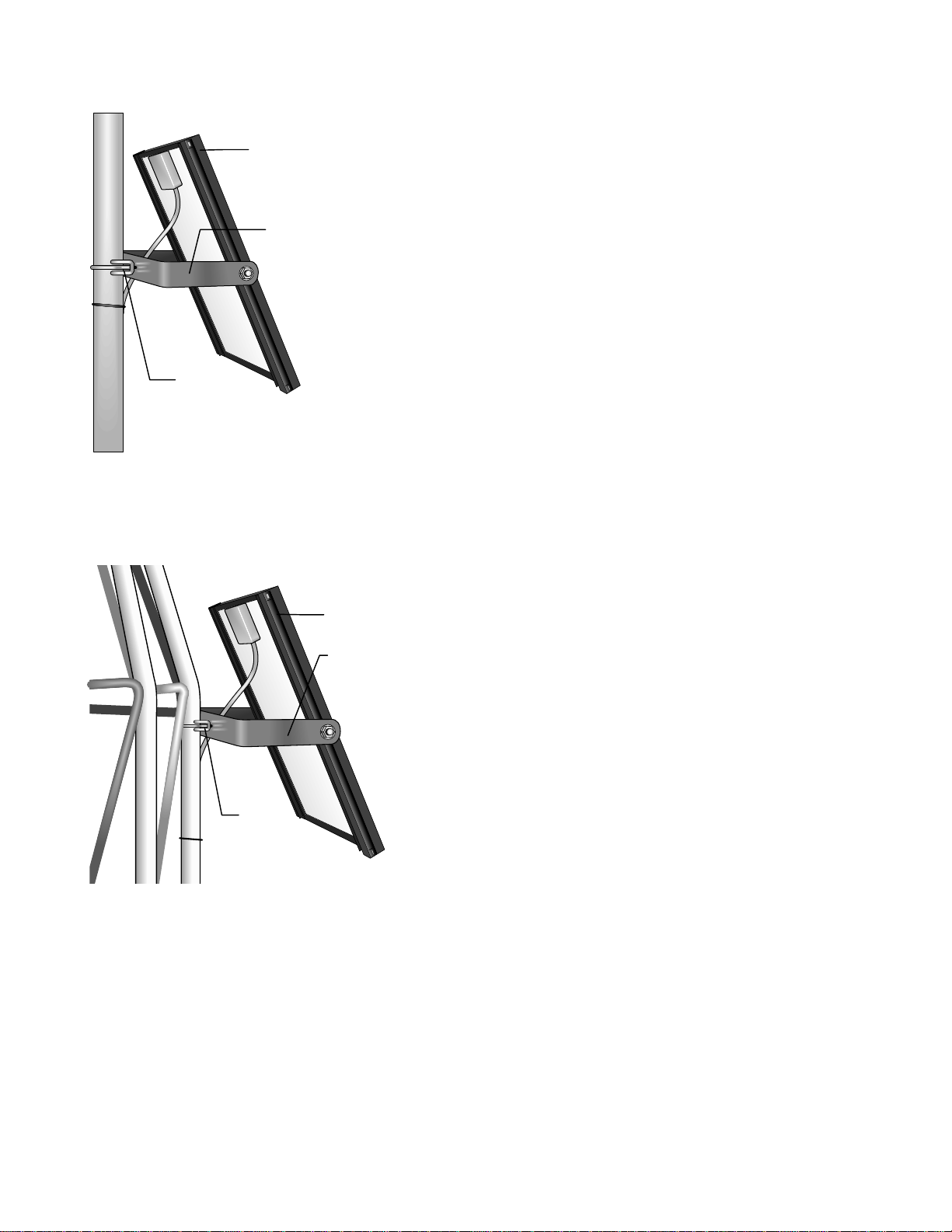
2.6 SENSOR MOUNTING BRACKETS
Mounting brackets provide a means of mounting
the sensors to the tripod. Bracket mounting
heights are referenced from the top of the bell
reducer; orientation is shown in Figure 2-3.
4. Extend each turnbuckle to its functional limit
5. Attach the loop-end of the turnbuckles to
the free end of each wire rope as shown in
Figure 2-8. Use the remaining thimbles and
u-bolts as done in step 1. Only fingertighten the u-bolts, however.
2.6.1 019ALU CROSSARM SENSOR MOUNT
Attach the 019ALU to the mast as shown in
Figure 2-9.
Slide the center NU-RAIL connector of the
019ALU down the crossarm mount (short pipe)
until it rests on top of the bell reducer. In most
applications, the center of the NU-RAIL
connector should be about 113" above the
ground surface. Orient the 019ALU in a
East/West direction with the 3/4" NU-RAIL
facing East (northern hemisphere) and tighten
the set screws. If the 025 Crossarm Stand is
used (Section 2.6.4), orient the 019ALU NorthSouth with the 3/4" NU-RAIL facing South.
Lightning Rod
REGCOMENDED
FeedSENSORS
27115
Serial
PortlandOr USA
REGCOMENDED
FeedSENSORS
Serial27115 27115
PortlandOr USA
REGCOMENDED
FeedSENSORS
27115
Serial
PortlandOr USA
FIGURE 2-8. Turnbuckle Assembly
6. Place the hook-end of each turnbuckle into
a bottom plate, in an orderly fashion, so that
each wire rope spans to the top plate
untangled and unobstructed.
2-6
019ALU
FIGURE 2-9. 019ALU Crossarm and
Lightning Rod
Page 19
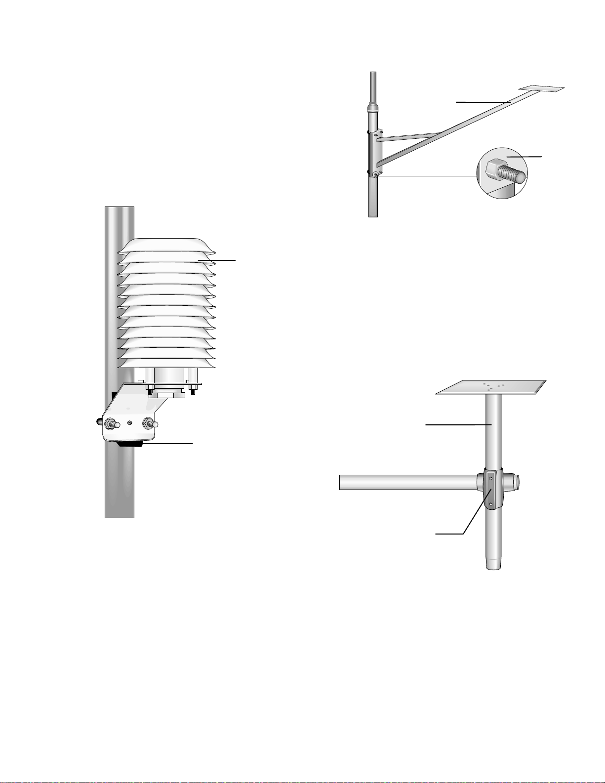
2.6.2 GILL RADIATION SHIELDS
g
SECTION 2. TRIPOD INSTALLATION
Attach the Gill Radiation Shield (41002, 41004
and 41301) to the mast as shown in Figure 2-10.
Position the radiation shield on the side of the
mast that faces the prevailing wind, with the top
of the black plastic mounting base 36" down
from the top of the bell reducer on the CM10, or
against the bottom of the bell reducer on the
CM6.
Gill Radiation
Shield
015
Mounting
Base
FIGURE 2-11. 015 Pyranometer
Mounting Arm
2.6.4 025 PYRANOMETER CROSSARM STAND
Attach the 025 Pyranometer Crossarm Stand to
the 019ALU as shown in Figure 2-12.
Position the mounting plate 5" above the 3/4"
NU-RAIL and tighten the set screws.
Black Plastic
Mountin
FIGURE 2-10. Gill Radiation Shield
2.6.3 015 PYRANOMETER MOUNTING ARM
Attach the 015 Pyranometer Mounting Arm to
the mast as shown in Figure 2-11.
Position the 015 on the south side of the mast
(northern hemisphere), with the top of the
mounting base 17" down from the top of the bell
reducer on the CM10, or 3 1/2" down on the
CM6.
Base
025
3/4” NU-RAIL
FIGURE 2-12. 025 Pyranometer
Crossarm Stand
2-7
Page 20

Page 21

SECTION 3. METDATA1 INSTRUMENTATION INSTALLATION
3.1 ENCLOSURE, DATALOGGER,
POWER SUPPLY
All instrumentation (datalogger, power supply,
sensor interface board, communications or data
retrieval peripherals) are mounted in the
MetData1 enclosure. Bulkhead connectors are
provided on the enclosure bottom for
connecting external sensors and devices as
illustrated in Figure 3.2-1.
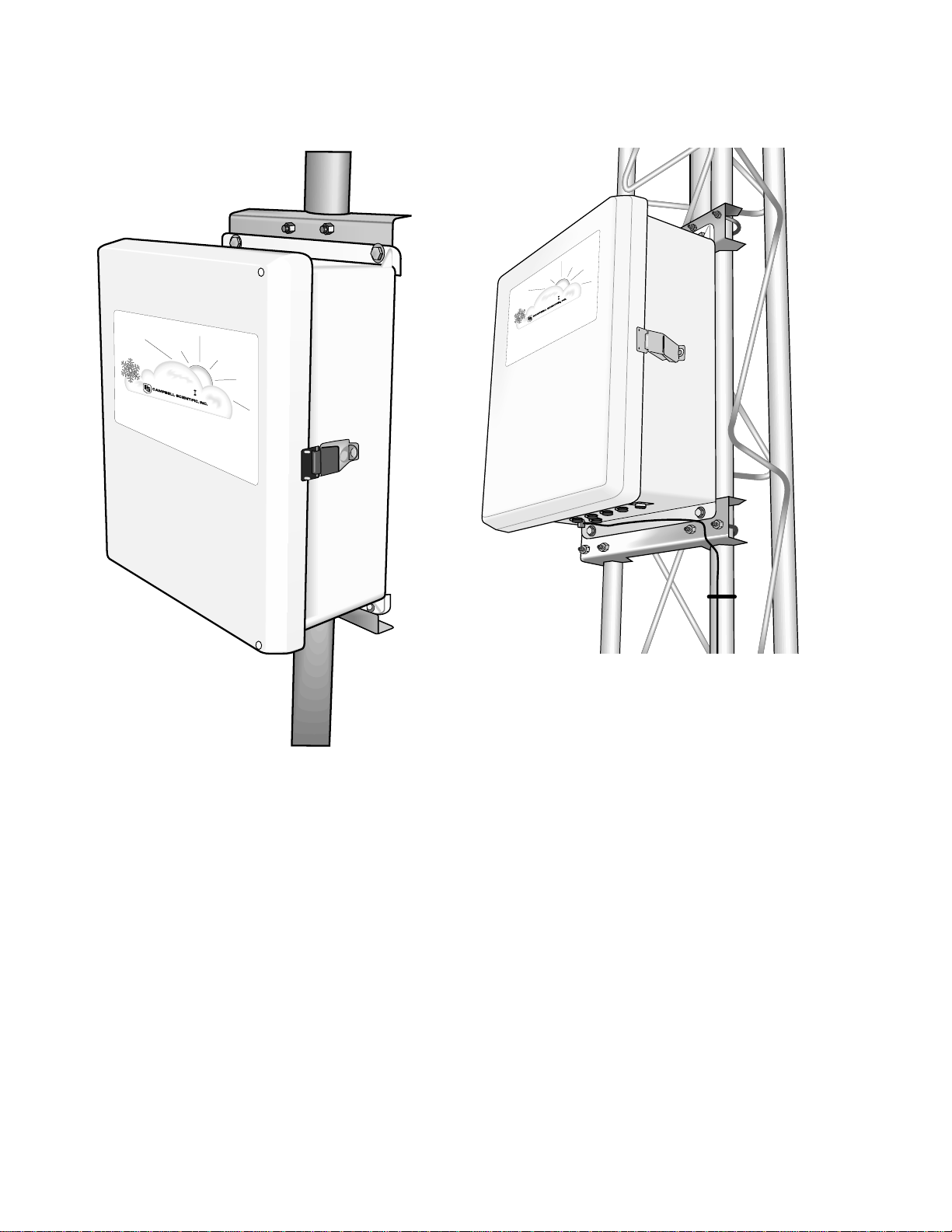
Step 1) Mount MetData1 enclosure on the
station platform as shown in Figures 3.1-1 or
3.1-2.
1. Position the enclosure on the north side
of the mast or tower (northern
hemisphere). Orient the enclosure so
that the latch is on the right side (as you
are facing the enclosure) and the
connector panel is on bottom. Tighten
U-bolts until enclosure is snug. Do not
over tighten since doing so may
damage the station platform.
2. Route the 13 AWG wire from the brass
grounding clamp on the tripod or tower
to the enclosure grounding lug. Insert
the end of the wire into the grounding
lug and tighten the set screw.
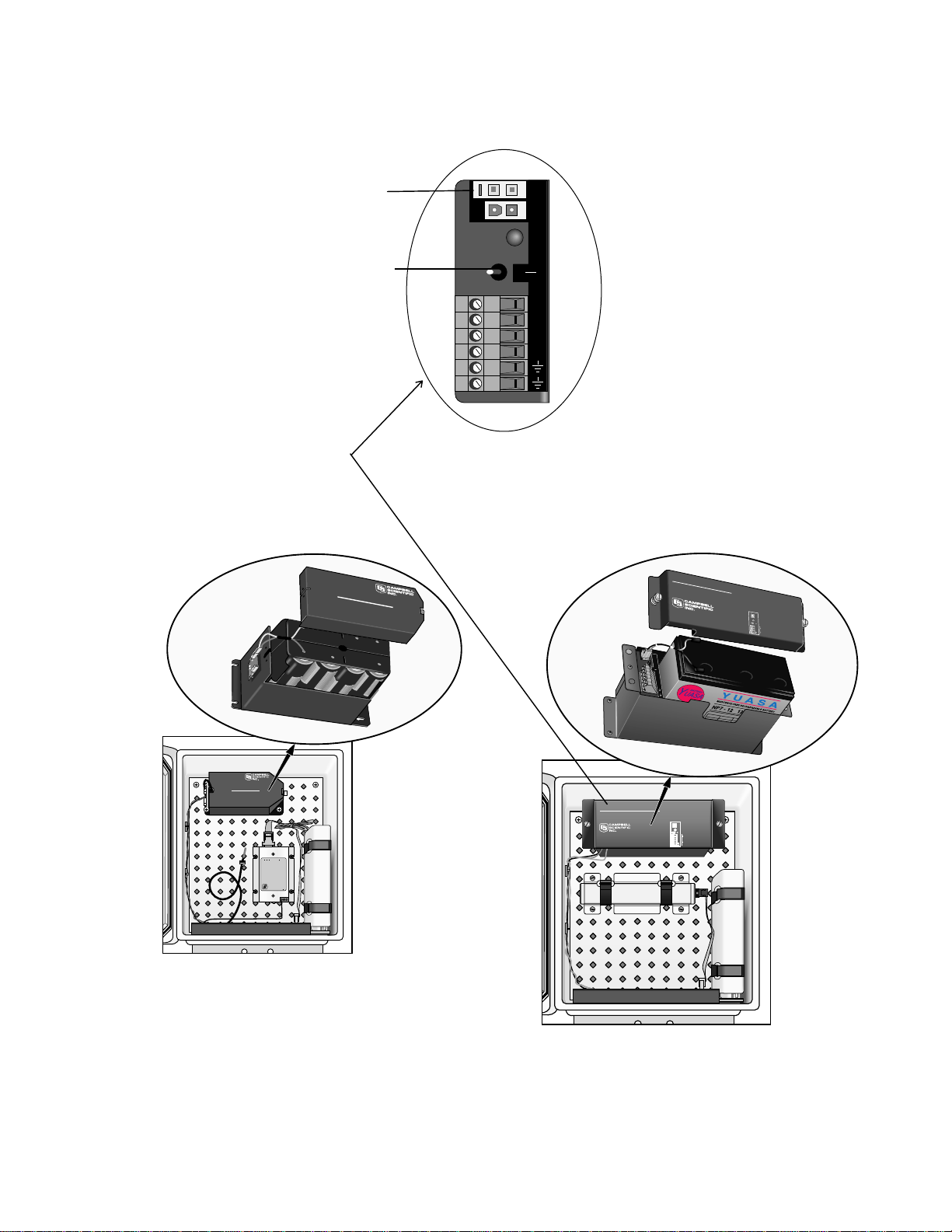
3.1.2 PS12LA 12V POWER SUPPLY WITH RECHARGEABLE BATTERY
The PS12LA houses a sealed monoblock
rechargeable battery. To install the battery,
loosen the two thumb screws and remove the
cover (Figure 3.1-5).
1. With the PS12 power switch "OFF", insert
the battery and plug the battery lead into the
connector labeled "INT". (Figure 3.1-3)
2. An unregulated solar panel (Section 3.1.3) or
charging wall plug transformer should be
connected to the MetData1 at all times when
the PS12LA is the power supply option. Power
connection port is shown in Figure 3.2-1.
3. Turn power switch to "ON", and replace the
cover.
3.1.3 MSX10 SOLAR PANEL
MetData1 Solar panels purchased from CSI are
shipped with a power connector attached.
1. Mount the MSX10 solar panel to the tower
so that it faces south (northern hemisphere)
as shown in Figure 3.1-6 or 3.1-7. Position
the MSX10 as high off the ground as
practical, ensuring that it cannot interfere
with air flow or sunlight around the sensors.
Step 2) Open enclosure by springing the latch
on the right side.
Step 3) Install the battery pack option as
described in sections 3.1.1 or 3.1.2. Installation
of an MSX10 solar panel is described in section
3.1.3.
Step 3) Place a packet of desiccant in the
desiccant holder located inside the enclosure
lid. Close the enclosure and secure the latch.
A lock may be used on the latch for extra
security.
3.1.1 BPALK 12 VOLT POWER SUPPLY
The BPALK houses 8 “D” cell batteries. To
install the battery pack, loosen the thumb screw
and remove cover. Insert the battery pack and
plug the battery lead into the connector labeled
internal (Figure 3.1-4).
2. The solar panel should be oriented to
receive maximum insolation over the
course of the year. Suggested tilt angles
(referenced to the horizontal plane) are
listed below.
Site Latitude Tilt Angle
0 to 10 degrees 10 degrees
11 to 20 Latitude + 5 degrees
21 to 45 Latitude + 10 degrees
46 to 65 Latitude + 15 degrees
>65 80 degrees
3. After determining the tilt angle, loosen the
two bolts that attach the mounting bracket
to the panel. Adjust the angle, then tighten
the bolts. Secure the lead wire to the mast
using wire ties.
4. Connect the solar panel to the MetData1
enclosure at the connection port labeled
"AC/SOLAR" as shown in Figure 3.2-1.
3-1
Page 22
SECTION 3. INSTRUMENTATION INSTALLATION
METDATA
LOGAN, UTAH - USA
METEOROLOGICAL
DATA
COLLECTION
STATION
LOGAN, UTAH - USA
DATA
METEOROLOGICAL
METDATA
COLLECTION
STATION
FIGURE 3.1-1. MetData1 Enclosure
on CM6 or CM10 Tripod
FIGURE 3.1-2. MetData1 Enclosure
on UT10 or UT30 Tower
3-2
Page 23
SECTION 3. INSTRUMENTATION INSTALLATION
INTERNAL BATTERY
MADE IN USA
12V ALKALINE BATTERY PACK
BPALK
Logan, Utah
TEMPORARY BATTERY
1012
INT
EXT
BATT
CHG
OFF
ON
CHG
CHG
CHG
*
CHARGING INSTRUCTION (AT 2000 )
WARNING:
MADE IN USA
WITH 12V CHARGING REGULATOR
PS12 POWER SUPPLY
Logan, Utah
PERMANENT DAMAGE TO RECHARGEABLE
CELLS MAY RESULT IF DISCARGED
BELOW 10.5 VOLTS
FUNCTION
INT
EXT
BAT
CHG
OFF
ON
CHG
CHG
+12
+12
PS12 BATTERY
EXTERNAL BATTERY - DO NOT USE WITH
INTERNAL RECHARGEABLE BATTERY
POWER TO +12 TERMINALS
INPUT FROM CHARGER OR SOLAR PANEL
16-26 VDC OR AC RMS: POSITIVE TO
EITHER TERMINAL, NEGATIVE TO OTHER
POWER TO DATALOGGER OR
12V PERIPHERALS
Internal Battery
Connector
Power Switch
INT
BATT
EXT
CHG
ON
OFF
CHG
CHG
+12
+12
FIGURE 3.1-3. PS12LA/CH12R Wiring
and Switch Panel
Alkaline
Pannasonic
D
D
Alkaline
INTERNAL BATTERY
BPALK
12V ALKALINE BATTERY PACK
TEMPARARY BATTER
MADE IN USA
Logan, Utah
GND
TIP
CAMPBELL
SCIENTIFIC
INC.
RING
SLKH AKDI AKLDI ALKDI LA FKA DAMD OQO
KDIA AKDH;A AADKFH ALDJ DKF A DLDL AKDIW'OR LDO
Pannasonic
PHONE
MADE IN USA
5021
DC112 MODEM
O/I
S/N
LDIFL AKD AKDHLA FKA ALKADO WO
ALKDIG ALKALKD ALK AK ALKDI AJF W OWOW AL
LID GLAIG ALKD I AKG WI9
DK DKIEL AKHIW ALKDO A DL ALJOW APW A PW AKDO AOWOP AF A VPAF
AKI ADIFW E OEI AL DFIW OKD ALD LADFOPWE ADLKF WOFJ AEIFIJO'AA
SKD;WO AKOW AIFWOP AKFOW AKDF ALKDF AFAFD AFAD A AFADFGGH
KJOW IOS ;SAO ALGFIVKAIAOF AKLKFGOA GKJFNMNAL ALFA ALK VOLAO
KOW FAOIFJG ALVOADFAF
Alkaline
Pannasonic
FIGURE 3.1-4. BPALK in MetData1
Enclosure
D
D
Alkaline
Pannasonic
MADE IN USA
WARNING:
PERMANENT DAMAGE TO RECHARGEABLE
CELLS MAY RESULT IF DISCHARGED
BELOW 10.5 VOLTS
FUNCTION
INT
PS12 BATTERY
BAT
EXTERNAL BATTERY - DO NOT USE WITH
EXT
INTERNAL RECHARGEABLE BATTERY
CHARGE VOLTAGE PRESENT
CHG
ON
OFF
INPUT FROM CHARGER OR SOLAR PANEL
CHG
16-26 VDC OR AC RMS: POSITIVE TO
CHG
EITHER TERMINAL, NEGATIVE TO OTHER
+12
+12
POWER TO DATALOGGER OR
12V PERIPHERALS
PS12 POWER SUPPLY
WITH 12V CHARGING REGULATOR
FIGURE 3.1-5. PS12LA in MetData1
Enclosure
3-3
Page 24
SECTION 3. INSTRUMENTATION INSTALLATION
MSX10
Mounting
Bracket
U-bolt
FIGURE 3.1-6. MSX10 Solar Panel
on CM6 or CM10 Tripod
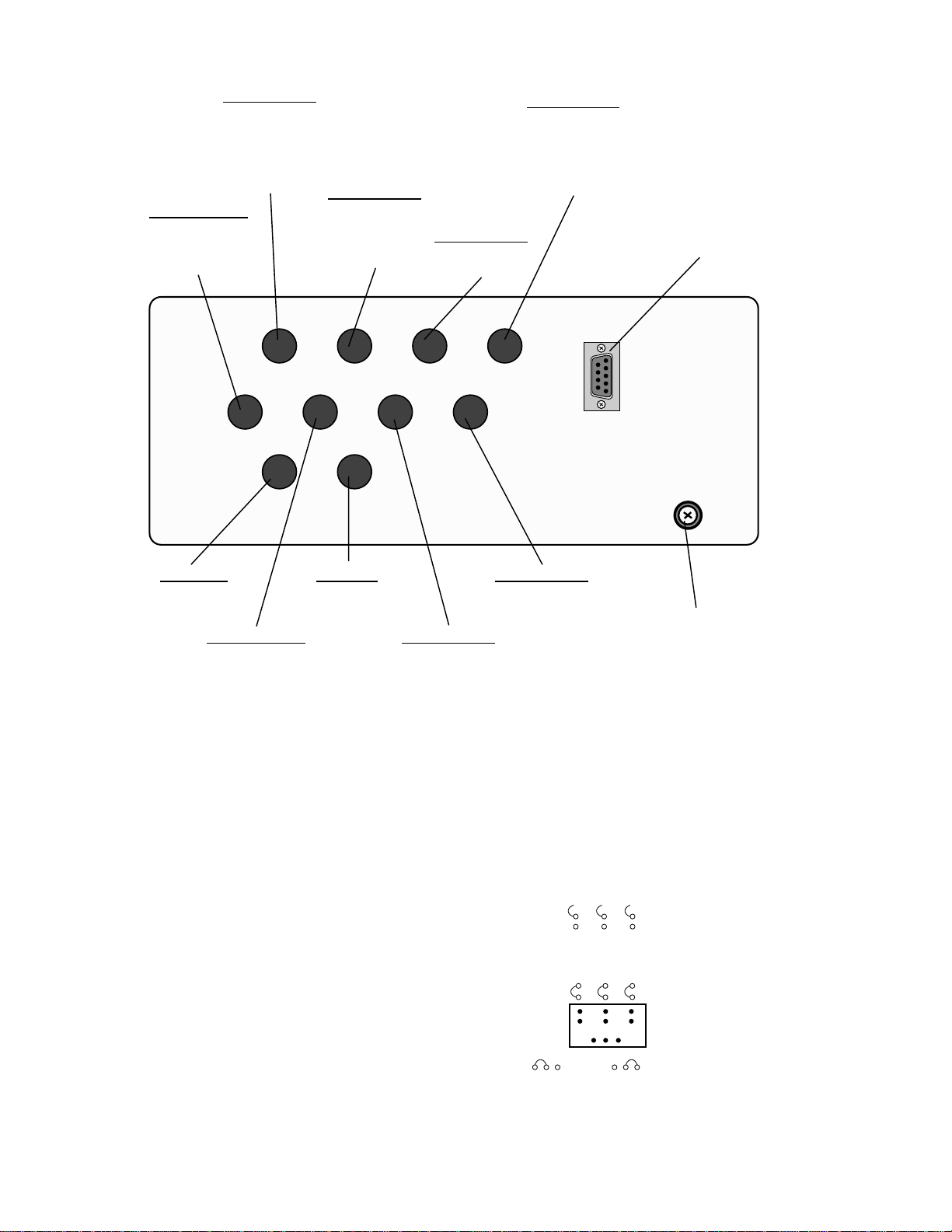
3.2 SENSOR CONNECTION
External MetData1 sensors connect to one of
seven bulkhead connectors on the bottom of
the MetData1 enclosure, as shown in Figure
3.2-1. Telephone and short haul modem wires
connect to connector #8. All power connections
occur at the AC/solar connector. Coaxial
bulkhead connectors are installed in the “popout”. The ground chuck should be connected to
earth ground.
The CS105MD mounts in the enclosure as
shown in Figure 3.12-2. Connect to internal
wiring panel of MetData1 as shown below:
Green ---------- 6H
White ---------- 6L
Black ---------- GND
Red ---------- 12V Switch
MSX10
Mounting
Bracket
U-bolt
FIGURE 3.1-7. MSX10 Solar Panel
on UT10 or UT30 Tower
3-4
Page 25
SECTION 3. INSTRUMENTATION INSTALLATION
CS800Default
HMP35C
LI190SB
LI200S
CS500\HMP45C
Open
Open
#1 #2 #3
#4
Connector #2
Connector #1*
HMP45C-LC
CS500-LC
HMP35C-LC
034A-LC
05103-LC
05305-LC
CS800*
03001-LC
Connector #4
CS615-LC
108-LC
107-LC
237-LC
Rad Modem Connector
Connector #6
SR50-LC
253-LC
Connector #8
Telephone and
Met Rad-L
Met Phone-L
Met Voice-L
Campbell Scientific
Serial I/O Connection
“Pop Out”
Coaxial
Connections
Connector #3*
LI190SB-LC
LI200S-LC
LI200X-LC
AC/Solar
MSX10-C
AC Wall Charger
Connector #5
CS700-LC
TE525-LC
TE525WS-LC
Connector #7
237-LC
107-LC
108-LC
To Earth Ground
TE525MM-LC
*Configure MetData1 jumpers as shown in Figure 3.2-2.
FIGURE 3.2-1. Illustration of MetData1
External bottom panel showing sensor, communication, power, and ground connections.
HMP35C #1 Closed
CS500 #1 Open
HMP45C #1 Open
CS800 #4 Right
LI190SB #3 Closed
#2 Open
LI200S #2 Closed
#3 Open
LI200X #2, #3 Open
FIGURE 3.2-2. MetData1 Jumper Configuration
3-5
Page 26

SECTION 3. INSTRUMENTATION INSTALLATION
3.3 COMMUNICATION AND DATA STORAGE PERIPHERALS FOR METDATA1
One or more peripherals (i.e., storage modules,
modems, relay drivers, etc.) can be mounted to
the MetData1 enclosure backplate.
3.3.1 SM192/SM716 STORAGE MODULE
Storage modules extend the amount of memory
that is available for storing data, provide on-site
backup for data and programs, and provide a
means of transporting data from remote sites.
Mount the SM192 mounting bracket to the
enclosure backplate as shown in Figure 3.3-1
using the four nylon inserts and screws
provided.
Connect the storage module to the MetData1’s
I/O port with the SC12 cable. Place the storage
module in the bracket and fasten the Velcro
straps.
SC12 Cable
3.3.2 MET PHONE COM200/VS1/COM300 PHONE MODEMS
The Met Phone Kit contains:
(1) Phone Modem
(1) SC12 Cable
(1) RJ-11 Patch Cord (12”)
(4) Nylon Backplate Inserts
(4) Screws
(1) Direct Bury Splice Kit
(1) Telephone Leader with Connector (20’)
Phone Modems enable communication
between the MetData1 and a PC (with Hayes
compatible Phone Modem) over a dedicated
phone line (Figure 3.3-2). An external phone
connection cable is provided. Connect the
external cable connector end into MetData1
connector #8. Connect the other end to the
telephone line in the telephone service box.
Install the Met Phone Kit as shown in Figure
3.2-2.
1. Mount the phone modem to the enclosure
backplate with the nylon inserts and screws.
SM192
Mounting
Bracket
FIGURE 3.3-1. SM192/SM716 Storage
SM192 or SM716
Storage Module
Module
The telephone company generally provides
surge protection. Surge protection is also
built into the MetData1 RJ11C jack.
2. Connect the modem 9-pin port to the
MetData1 9-pin port with the SC12 cable.
3. Connect the modem RJ-11 port to the
MetData1 RJ-11 port with the RJ-11 patch
cord.
4. Connect modem ground to MetData1
ground.
5. Connect the telephone leader cable to
connector #8 on the external bottom panel
of the MetData1 (see Figure 3.2-1).
6. Connect the tip and ring lines of the
telephone leader to the commercial phone
system, either at a service box or using the
direct bury splice kit provided.
3-6
Page 27

SECTION 3. INSTRUMENTATION INSTALLATION
CAMPBELL
SCIENTIFIC
INC.
VS1 VOICE SYNTHESIZER
Complies with Part 68, FCC rules. FCC Registration No. B9QUSA-75378-MM-T
Ringer Equivalence 0.6B. Required Connector USOC RJ11C. Canadian Load No.5
This equipment complies with the requirements in Part 15 of FCC Rules for Class A
computing device. Operation of this equipment in a residential area may cause
unacceptable interference to radio and TV reception requiring the operator to take
whatever steps are necessary to correct the interference.
S/N
1001
MADE IN USA
GND
RING
TIP
SC12 Cable
GND
TIP
RING
PHONE
MADE IN USA
CAMPBELL
SCIENTIFIC
INC.
5021
DC112 MODEM
O/I
S/N
SLKH AKDI AKLDI ALKDI LA FKA DAMD OQO
KDIA AKDH;A AADKFH ALDJ DKF A DLDL AKDIW'OR LDO
LDIFL AKD AKDHLA FKA ALKADO WO
ALKDIG ALKALKD ALK AK ALKDI AJF W OWOW AL
LID GLAIG ALKD I AKG WI9
DK DKIEL AKHIW ALKDO A DL ALJOW APW A PW AKDO AOWOP AF A VPAF
AKI ADIFW E OEI AL DFIW OKD ALD LADFOPWE ADLKF WOFJ AEIFIJO'AA
SKD;WO AKOW AIFWOP AKFOW AKDF ALKDF AFAFD AFAD A AFADFGGH
KJOW IOS ;SAO ALGFIVKAIAOF AKLKFGOA GKJFNMNAL ALFA ALK VOLAO
KOW FAOIFJG ALVOADFAF
Ground Cable
RJ-11 Patch
Cord
Modem
FIGURE 3.3-2. Telephone Modem
Installation
2. Install the modem and cellular transceiver
with the nylon inserts and screws provided.
3. Connect the modem 9-pin port to the
MetData1 internal 9-pin port with the SC12
cable.
4. Connect the modem RJ-11 port to the
MetData1 RJ-11 port with the RJ-11 patch
cord.
5. Connect the antenna to the external side of
the coaxial bulkhead connector.
6. Connect the 12V line and ground lines from
the COM100 to the PS12 power supply.
Modem
Ground
Cable
3.3.3 METCELL COM100 CELLULAR TRANSCEIVER
The MetCell COM100 requires the use of the
CR10KD or SC32A for initial programming of
the MetData1.
CAUTION: Do not connect transceiver
power until antenna is connected.
Cellular service and programming of your
transceiver must be coordinated with your local
cellular provider. A cellular transceiver enables
communication between the datalogger and a
PC (with a Hayes compatible phone modem)
over cellular phone service.
Install the MetCell cell phone kit as shown in
Figure 3.3-3.
1. As shown in Figure 3.2-1, a “pop-out” plug is
provided adjacent to the AC/Solar connector
for installing the coaxial bulkhead connector.
Remove the “pop-out” plug by pushing it out
from inside the enclosure with a screw
driver. Wear gloves while doing this to
protect your hands when the plug gives way.
Install the coaxial bulkhead connector.
Antenna Cable
to Coaxial
Bulkhead
Connector
FIGURE 3.3-3. Phone Installation
3.3.4 METRAD SRM-5A RAD MODEM AND SC932C INTERFACE
Rad Modems enable communication between a
datalogger and computer over two twisted pairs
of wires. The maximum distance between
modems is determined by baud rate and wire
gauge. At 9600 baud the approximate range is
4.0 miles.
SC12
Cable
3-7
Page 28

SECTION 3. INSTRUMENTATION INSTALLATION
The MetRad kit includes:
(2) Rad modems
(2) Nylon Inserts
(2) Screws
(1) Rad Modem 4-Wire Patch Cable
(1) SC932C 9-Pin Interface
(1) Ground Wire
(1) Surge Protector Kit
(2) Burial Splice Kits
(1) Mounting Bracket
(1) PC 4-Wire Leader
(1) Met-Rad 4-Wire Leader with Connector
(1) Length of User-Supplied Wire
(Supplier: Anixter, P/N F-02P22BPN,
708-677-2600)
3.3.4.1 MetRad at MetData1
Install the MetRad as shown in Figure 3.3-4.
1. Plug the SRM-5A into the SC932C.
Position the notched tabs in the mounting
bracket over the two screws in the SRM-5A
(refer to Figure 3.3-4). Thread the SRM-5A
screws through the bracket and into
SC932C.
2. Mount the SRM-5A/SC932C mounting
bracket into the MetData1 using the 2 nylon
inserts and screws.
3.3.4.2 MetRad at the PC
1. Mount the Surge Protector to a flat surface
(close to the PC). Ground the center
terminal to an earth (or building) ground
using the 12 AWG ground wire.
2. Connect the 4-wire leader cable to the
SRM-5A as shown in Figure 3.3-4. Fasten
the cable to the strain relief tab with a cable
tie. Connect the SRM-5A to the PC's serial
port using an SC25PS cable for 25-pin
serial ports, or a PN7026 cable for a 9-pin
serial port.
3. Route the user-supplied cable from the
remote SRM-5A, and the cable from the
SRM-5A attached to the computer to the
surge protector box. Connect the cables to
the surge protector terminals as shown in
Figure 3.3-5.
SC12 Cable
QC
--
RCV
+G +
XMT
CAMPBELL
SCIENTIFIC LTD
SC932 - S/N E1055
3. Connect the SC932C 9-pin port to the
MetData1 internal 9-pin port with the SC12
cable.
4. Connect the SRM-5A to the MetData1 with
the short 4 wire patch cord provided. Match
wire labels to MetData wiring panel labels
(+XMT to +XMT, etc.).
5. Connect the 20 foot 4 wire leader to
connector #8 on the bottom external
MetData1 panel. See Figure 3.2-1 for
connector #8 location. Splice this cable to
the user supplied cable using the burial
splice kits.
SRM-5A
SC932C
FIGURE 3.3-4. SRM-5A and SC932C
in MetData1
3-8
Page 29

SECTION 3. INSTRUMENTATION INSTALLATION
PC
SRM-6A
- RCV (black)
+ RCV (red)
- XMT (white)
+ XMT (green)
+ RCV (red)
- RCV (black)
+ XMT (green)
- XMT (white)
METDATA 1 WIRING PANEL
METDATA 1 ENCLOSURE
Surge
+ XMT (green)
- XMT (white)
+ RCV (red)
- RCV (black)
Protector
Earth Ground
User
Supplied
1
Cable
2
3
4
Splices
1
2
3
4
+ RCV
- RCV
+ XMT
- XMT
RED
BLACK
GREEN
WHITE
QC
CAMPBELL
SCIENTIFIC LTD
SC932 - S/N E1055
METDATA 1 ENCLOSURE
To # 8
External Connector
FIGURE 3.3-5. SRM-5A Wiring
3.3.5 RF95 RF MODEM AND RF100/RF200
TRANSCEIVER
CAUTION: Do not connect transceiver
power until antenna is connected.
Radiotelemetry (RF) enables communications
between one or more MetData1s/dataloggers
and a PC over an FCC-assigned radio
frequency in the VHF or UHF band. The
maximum distance between any two
communicating stations is approximately 20
miles and must be line-of-sight. Longer
distances and rough terrain may require
intermediate repeater station(s). Refer to the
Radiotelemetry Network Applications manual for
RF repeater stations and RF Networks
accessed remotely by phone.
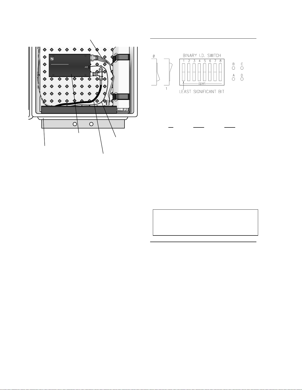
3.3.5.1 RF95 Modem and RF100/RF200 Transceiver at the MetData1
1. Remove the four screws that attach the lid
to the RF95 modem. Remove the RF95
case lid. Remove the center screw from
the circuit board. Remove the circuit board.
2. Mount the bottom half of the RF95 case into
the MetData1, orienting it as shown in
Figure 3.3-5. Replace the circuit board and
center screw.
3. Set the dip switches on the circuit board to
the appropriate Station ID (Table 3.3-1).
Each RF95 must have a unique station ID;
address 1 is usually used for the base
station, address 2 for first remote station,
address 3 for the next remote station, etc.
Switch 9 should be in the "OPEN" position.
Do not tighten the four lid screws at this
time.
4. Replace the lid. Place the radio mounting
bracket and radio on the RF95 and tighten
the four lid screws.
5. Locate the short coaxial cable with the
bulkhead connector on the end. Install the
3-9
Page 30

SECTION 3. INSTRUMENTATION INSTALLATION
bulkhead connector into the “punch-out”
hole, located as shown in Figure 3.3-5.
Install the bulkhead connector so that the
cable is inside the MetData1. Connect the
other end of the cable to the radio’s BNC
connector.
6. Mount the antenna to the mast according to
the manufacturer's instructions. Connect
the antenna cable to the antenna and route
the cable. Connect the antenna cable to
the outside end of the coaxial bulkhead
connector as shown in Figure 3.3-5. Wrap
the connection with the self-vulcanizing
rubber provided.
MD9
MULTIDROP INTERFACE
CAMPBELL
SCIENTIFIC
INC.
CARRIER DETECT
FCC ID: ATH90F0233420050
E.F.JOHNSON CO. U.S.A.
E.F. JOHNSON CANADA INC.
mfg by E.F. JOHNSON USA
DOC T.A. 89178
Serial No3400T144A 17858
DL 3420
MADE IN USA
TRANSCEIVER
SERIAL I/O
TABLE 3.3-1. Station ID Numbers and
Corresponding Switch Settings**
Station Switch Settings
ID 1234
56789
0 0000 0000X
1 1000 0000X
2 0100 0000X
3 1100 0000X
4 0010 0000X
5 1010 0000X
6 0110 0000X
7 1110 0000X
8 0001 0000X
9 1001 0000X
10 0101 0000X
11 1101 0000X
12 0011 0000X
*255 1111 1111X
* Station ID 255 is reserved for phone-to-RF
base stations.
** See Appendix A in the Radiotelemetry
Network Applications Manual for a table of
switch settings.
Cable to
Antenna
Coaxial Bulkhead Connector (wrap
with supplied self-vulcanizing rubber)
FIGURE 3.3-5. RF95 RF Modem and
RF100/RF200 Transceiver
3-10
SC12 Cable
Radio
Transceiver
3.3.5.2 RF232 RF Base Station
1. Install the base station antenna according
to the manufacturer's instructions. Connect
the antenna cable to the antenna and route
the cable to the RF232.
2. With the power cord disconnected, remove the
four screws that attach the RF232 lid. Remove
the lid, and install the RF200 transceiver as
shown in Figure 3.3-6. Connect the red wire to
the "12 V" terminal, and the black wire to the
" terminal inside the RF232. Connect the
"
multi-colored ribbon cable to the RF modem;
make sure that the keyway is properly aligned.
3. Connect the antenna cable to the antenna
connector on the RF200. Reassemble the
RF232 lid using the screws previously
removed.
Page 31

SECTION 3. INSTRUMENTATION INSTALLATION
+12V
4. With the power switch "OFF", connect the
power cord to 110V AC. Connect the serial port
to the computer's serial port using an SC25PS
cable for a 25-pin serial port, or a PN7026 cable
for a 9-pin serial port. Toggle the power switch
to "ON" to operate the RF232.
INTERNATIONAL
IP
POWER
IHB12-1.7
OUTPUT:
MEXICO
92109
12DC AT
1.7 AMPS
EXTERNAL FUSE RECOUNTER
EXIT
!
57 - 63 Hz
AC INPUT
120
100
230-240
FOR USE AT
1&3
1&2
2&3
2&3
JUMPER
1&2
1&3
1&4
1&5
1&4
1&5
APPLY AC
MAX (CURENT)
.25A
.5A
FUSE RATING
MADE IN THE
USA
2N3055
DL 3420
E.F. JOHNSON CANADA INC.
E.F.JOHNSON CO. U.S.A.
FCC ID: ATH90F0233420050
Serial No3400T144A 17858
DOC T.A. 89178
mfg by E.F. JOHNSON USA
Radio
Antenna Cable
12V and G
Terminals
Power
Switch
Serial
Port
FIGURE 3.3-6. RF232 Base Station
Installation
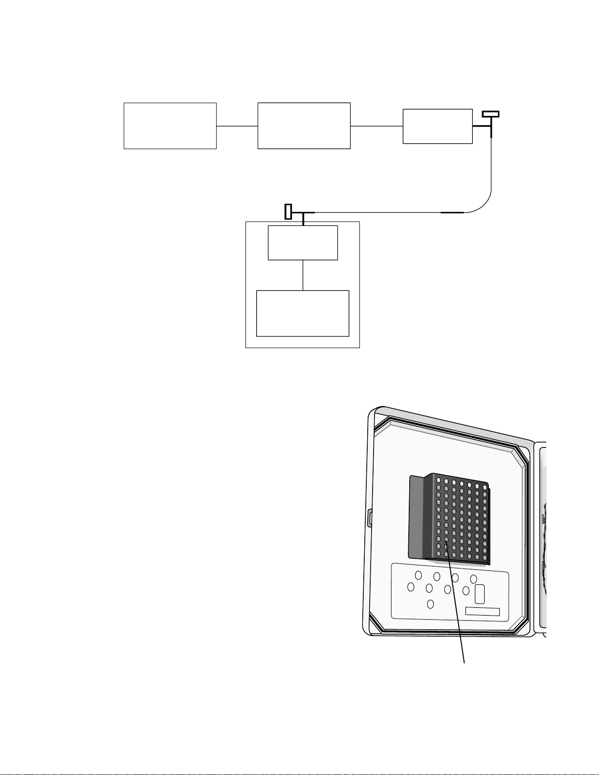
3.3.6 MD9 MULTIDROP INTERFACE
The MD9 Multidrop Interface enables
communication with one or more
MetData1s/dataloggers and the computer over
a single 75 ohm coaxial cable. An MD9 network
can be connected directly to a PC, or can be
connected to a telephone modem (refer to the
MD9 Manual) and accessed remotely.
Total coax length may be up to three miles.
Since each MD9 attenuates the signal 0.2 db,
the maximum length depends on the number of
MD9s in the network (refer to the MD9 manual).
Coaxial cable and BNC connectors may be
ordered from CSI, or purchased locally (Belden
Type 9100 RG59/U or equivalent). Call Belden
Wire and Cable at (317) 983-5200 for the name
of a local distributor.
Installation requirements depend on the type of
cable that is used, and how it is installed (direct
burial, conduit, etc.). In general, follow state
and local electrical codes.
3.3.6.1 MD9 Multidrop Interface at the MetData1
1. Remove the four screws that attach the lid
to the MD9. Remove the lid. Remove the
center screw from the circuit board.
Carefully remove the circuit board.
2. Mount the lower half of the case into the
MetData1 using the inserts and screws
provided. Replace the circuit board and
center screw.
3. Set the dip switches on the circuit board to
the appropriate Station ID (Table 3.3-2). Each
MD9 must have a unique ID; address 1 is
usually used for the MD9 at the computer,
address 2 for the next MD9, address 3 for the
next MD9, etc. The default baud rate is 9600,
which can be changed with the jumpers next
to the dip switches (Table 3.3-2).
4. Replace the lid.
5. A “pop-out” plug is provided adjacent to the
AC/Solar connector for mounting the
coaxial bulkhead connector into the
enclosure as shown in Figure 3.3-5.
Remove the “pop-out” plug by pushing it out
from inside the enclosure with a screw
driver. Wear gloves while doing this to
protect your hands when the plug gives
way. Install the coaxial bulkhead connector.
Attach the short coaxial cable to the MD9’s
coax connectors to the inside end of the
bulkhead connector. Attach the main
coaxial cable to the outside end of the
bulkhead connector. Wrap the outside
connection with the provided selfvulcanizing rubber.
6. Route the coaxial cable(s) to the MD9.
Connect the cable(s) to the MD9 using the
BNC "T" provided. The first and last MD9s
of the network must be terminated with 75
ohm Coax Terminators (Model MD9CT) to
prevent signal reflection.
3.3.6.2 MD9 Multidrop Interface at the
Computer
Connect the MD9 and the SC532 9 Pin
Peripheral to RS232 Interface to the computer
as shown in Figure 3.3-8.
1. Connect the SC532 to the computer's serial
port using an SC25PS cable for a 25-pin
serial port, or a PN7026 cable for a 9-pin
serial port. Connect the MD9 to the SC532
with an SC12 cable.
2. Route the coaxial cable to the MD9;
connect the cable and an MD9CT to the
MD9 using the BNC "T" provided.
3-11
Page 32
SECTION 3. INSTRUMENTATION INSTALLATION
SC12 Cable
CAMPBELL
SCIENTIFIC
INC.
MD9
MULTIDROP INTERFACE
MADE IN USA
Position of Installed
Coaxial Bulkhead
Connector
MD9
SERIAL I/O
COAX
Ground Wire
Must be
Installed
Coaxial Cable to
Bulkhead Connector
FIGURE 3.3-7. MD9 Multidrop Interface
in MetData1
TABLE 3.3-2 Station ID Numbers and
Corresponding Switch Settings
9600 Baud 1200 Baud 300 Baud
A-B Short A-B Open A-B Short
C-D Short C-D Short C-D Open
Station Switch Settings
ID 1234
5678
0 0000 0000
1 1000 0000
2 0100 0000
3 1100 0000
4 0010 0000
5 1010 0000
6 0110 0000
7 1110 0000
8 0001 0000
9 1001 0000
10 0101 0000
11 1101 0000
12 0011 0000
*255 1111 1111
NOTE: Addresses 1-254 are valid for an
MD9 connected to a datalogger or computer.
Address 255 is used only when the MD9 is
connected to a telephone modem.
3-12
Page 33
SECTION 3. INSTRUMENTATION INSTALLATION
2
1
4
3
6
5
8
7
AC/SOLAR
SERIAL #:
SERIAL I/O
MD9CT
COMPUTER
SC532 MD9
SC12
COAX
CABLE
MD9
SC12
CSI
DATALOGGER
METDATA1
FIGURE 3.3-9. MD9 Multidrop Interface at the Computer and at the MetData1
3.4 SEALING AND DESICCATING THE ENCLOSURE
The MetData1 enclosure is supplied with desiccant
packs. The desiccant maintains a low humidity in
the enclosure to minimize the chance of
condensation on the instrumentation. The
desiccant must be changed periodically. Place
one or two desiccant packs into desiccant holder
just before leaving the installation site. Be sure to
close the lid. A desiccant change is indicated
when the internal MetData1 humidity sensor
measures 30% or higher. Keep unused desiccant
tightly sealed in an airtight container.
Desiccant
Holder
FIGURE 3.4-1. Inside MetData1 Lid
3-13
Page 34

Page 35
SECTION 4. SENSOR INSTALLATION
Sensor leads should be routed down the North side of the mast to the enclosure and secured with cable
ties.
4.1 034A MET ONE WINDSET
Mount the 034A to the 019ALU crossarm as
shown in Figure 4.1-1.
1. Place the 034A stem and bushing into the
3/4" x 1” NU-RAIL fitting.
2. With the shoulder screw in place, orient the
counter weight to point due south. See
Section 4.19 for final calibration.
3. Tighten the NU-RAIL set screws and
remove the shoulder screw.
Shoulder
Screw
4.2 014A MET ONE WIND SPEED SENSOR
Mount the 014A sensor to the 019ALU
crossarm as shown in Figure 4.2-1.
1. Insert the base of the sensor through the
3/4" NU-RAIL. Position the sensor 1" below
the NU-RAIL and tighten the set screws.
2. Connect the sensor lead to the sensor. A
small amount of lithium grease applied to
the threads of the connector will prevent
problems due to corrosion.
Feed SENSORS
Portland Or USA
REGCOMENDED
27115
Serial
014A
034A
Alignment
Screw
NU-RAIL
FIGURE 4.1-1. Met One 034A Wind Speed
and Direction Sensor
N
019ALU
FIGURE 4.2-1. Met One 014A Wind
Speed Sensor
4-1
Page 36
SECTION 4. SENSOR INSTALLATION
0
4.3 024A MET ONE WIND DIRECTION SENSOR
Mount the 024A sensor to the 019ALU
crossarm as shown in Figure 4.3-1.
1. Remove the hex-head screw located 3"
from the base of the sensor. Insert the
base of the sensor through the aluminum
bushing provided with the sensor. Align the
hole in the bushing with the hole in the
sensor and replace the screw.
2. Insert the base of the sensor through the 1"
NU-RAIL until the bushing screw rests on
the NU-RAIL. Orient the sensor so the
counter weight points south and tighten the
set screws (see Section 4.19 for final
calibration). Remove the shoulder screw to
allow the vane to rotate.
3. Connect the sensor lead to the sensor. A
small amount of lithium grease applied to
the threads of the connector will prevent
problems due to corrosion.
4.4 05103 AND 05305 RM YOUNG WIND MONITORS
Mount the 05103 (or 05305) to the 019ALU
crossarm as shown in Figure 4.4-1.
1. Position the top of the mounting post 5"
above the 1" NU-RAIL and tighten the set
screws.
2. Slide the orientation ring and the 05103
onto the mounting post. Rotate the sensor
base so that the square wiring box points
south. Engage the key in the orientation
ring with the keyway on the sensor and
tighten the band clamps (see Section 4.19
for final calibration).
3. Remove the plastic nut on the propeller
shaft. Slide the propeller onto the shaft
(face the side with the lettering out) and
replace the nut.
YOUNG
Shoulder Screw
24
REGCOMENDED
Feed SENSORS
Serial
27115
Portland Or USA
REGCOMENDED
Feed SENSORS
Serial 27115 27115
Portland Or USA
Aluminum Bushing
FIGURE 4.3-1. Met One 024A Wind
Direction Sensor
NU-RAIL
05103
YOUNG
Wiring Box
Mounting Post
019ALU
FIGURE 4.4-1. 05103 RM Young Wind
Monitor
4-2
Page 37
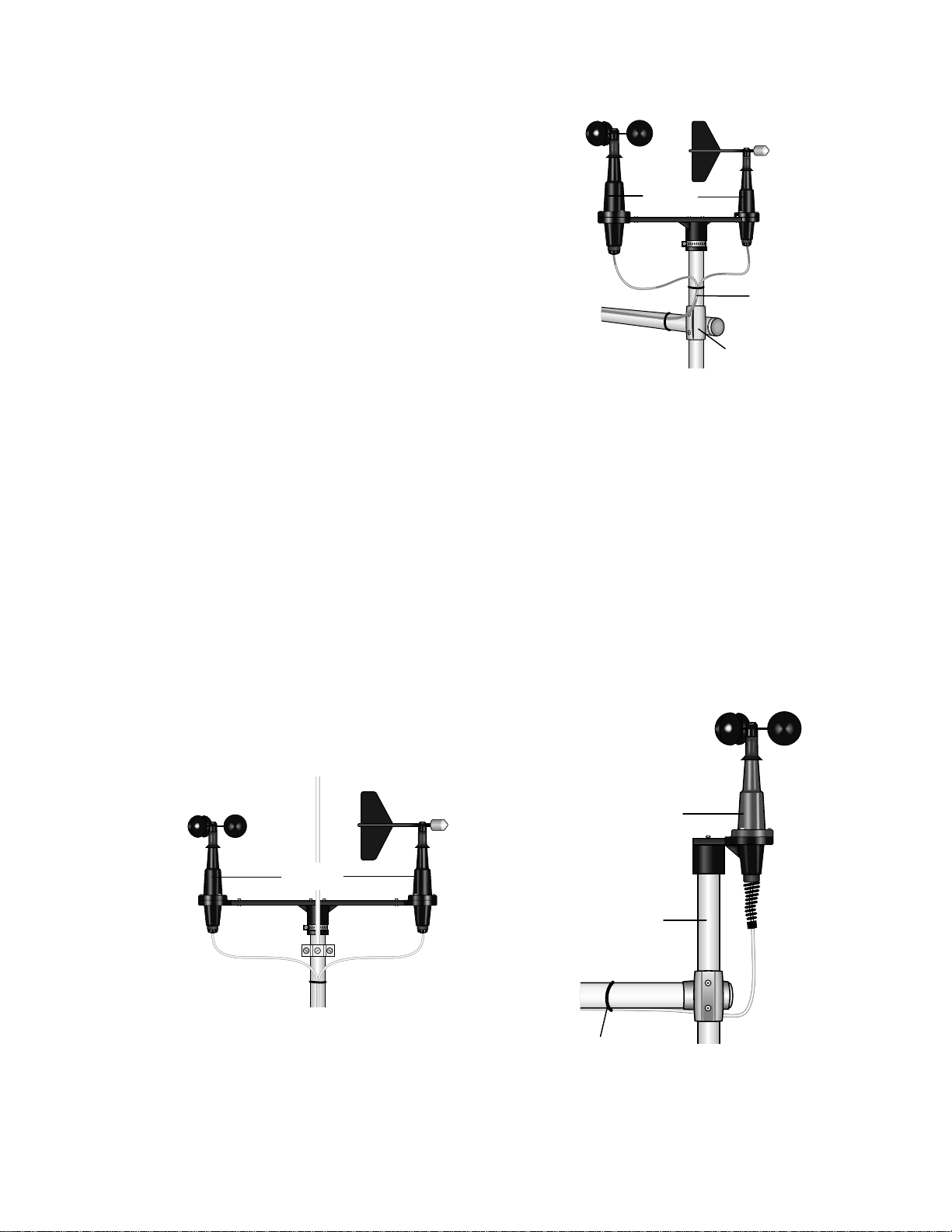
4.5 03001 RM YOUNG WIND SENTRY WIND SET
The 03001 can be mounted directly to the mast,
or to the 019ALU Crossarm.
4.5.1 03001 MOUNTED TO THE MAST
Mount the 03001 to the mast as shown in
Figure 4.5-1.
1. Slide the crossarm mounting bracket onto
the mast. Orient the crossarm so the vane
end points north, and tighten the band
clamp (see Section 4.19 for final
calibration).
2. Attach the cup assembly to the
anemometer shaft using the allen wrench
provided.
4.5.2 03001 MOUNTED TO 019ALU CROSSARM
Mount the 03001 to the 019ALU crossarm as
shown in Figure 4.5-2.
SECTION 4. SENSOR INSTALLATION
03001
Mounting Post
NU-RAIL
FIGURE 4.5-2. 03001 Mounted to
019ALU Crossarm
4.6 03101 RM YOUNG WIND SENTRY ANEMOMETER
Mount the 03101 to the 019ALU crossarm as
shown in Figure 4.6-1.
1. Position the top of the mounting post 5"
above the 3/4" NU-RAIL and tighten the set
screws.
2. Slide the crossarm mounting bracket onto
the mounting post. Orient the crossarm so
the vane end points north, and tighten the
band clamp (see Section 4.19 for final
calibration).
3. Attach the cup assembly to the
anemometer shaft using the allen wrench
provided.
03001
1. Screw the mounting post into the mounting
bracket on the sensor.
2. Position the top of the mounting post 5" above
the 3/4" NU-RAIL and tighten the set screws.
3. Attach the cup assembly to the anemometer
shaft using the allen wrench provided.
03101
Mounting Post
FIGURE 4.5-1. 03001 Mounted to the Mast
019ALU
FIGURE 4.6-1. 03101 RM Young Wind
Sentry Anemometer
4-3
Page 38
SECTION 4. SENSOR INSTALLATION
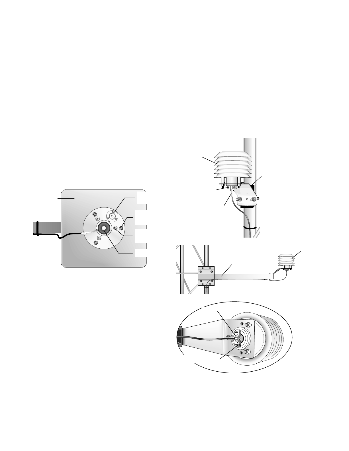
4.7 LICOR SILICON RADIATION
SENSORS (LI200X, LI200S, LI190SB)
Mount the Radiation Sensor to the LI2003S Base
and Leveling Fixture as shown in Figure 4.7-1.
1. Position the base of the sensor in the
mounting flange on the LI2003S, and
tighten the set screw with the allen wrench
provided. Adjust the three leveling screws
flush with the bottom of the LI2003S.
2. Mount the LI2003S to the 025 or 015
(Section 2.2) using the three mounting
screws provided. Do not tighten the screws
at this time.
3. Level the LI2003S using the bubble level
and leveling screws and tighten the
mounting screws. Remove the red
protective cap prior to use.
015 or 025
Bullseye
v
l
l
(3) Leveling
Screws
4.8 107/108 TEMPERATURE PROBE
Mount the 107 temperature probe inside the
41301 (UT6P) 6-Plate Gill Radiation Shield as
shown in Figure 4.8-1.
1. Loosen the two mounting clamp screws on
the base of the 41301 (UT6P). Insert the
107 probe through the mounting clamp until
the white heat shrink is even with the
bottom of the clamp.
2. Tighten the two screws evenly until the
clamp is snug against the sensor lead.
41301
Mounting Base
Mounting Clamp
107
(3) Mounting
Screws
Sensor
FIGURE 4.7-1. LI200X/LI200S/LI190SB and
LI2003S Leveling Fixture
UT6P
UT018
107
Mounting Clamp
FIGURE 4.8-1. 107 Temperature Probe
4-4
Page 39

SECTION 4. SENSOR INSTALLATION
4.9 107/108 SOIL TEMPERATURE PROBE
1. Select an undisturbed area of ground on the
side of the tower that will receive the least
amount of traffic. Route the sensor lead
from the datalogger to the selected area.
2. Dig a narrow trench next to the sensor lead,
ending the trench at least 6" short of the
probe tip. Lay the sensor lead into the
trench.
3. Use a screwdriver to poke a horizontal hole
into the undisturbed soil at the end of the
trench at the appropriate measurement
depth. Insert the probe tip into the hole and
carefully backfill the trench.
4. If bare soil is required, a soil sterilant such
as Paramitol can be applied to the area
where the probe is buried. Soil erosion can
be a problem when the probe is under bare
soil. To prevent erosion from occurring,
bury a 36” square frame constructed from
2” x 4" lumber around the probe, with the
top of the frame even with the soil surface.
4.10 CS500 VAISALA TEMPERATURE AND RH PROBE
Mount the CS500 probe inside the 41301
(UT6P) 6-Plate Gill Radiation shield as shown in
Figure 4.10-1.
1. Loosen the two mounting clamp screws on
the base of the radiation shield. Insert the
CS500 sensor through the clamp until the
base of the sensor is even with the bottom
of the clamp.
Tighten the two screws evenly until the clamp is
snug against the sensor base.
41031
Mounting
Clamp
CS500
Base
Mounting
Clamp
UTGP
UT018
CS500
Base
CS500
FIGURE 4.10-1. CS500 Temperature and
RH Probe
4-5
Page 40
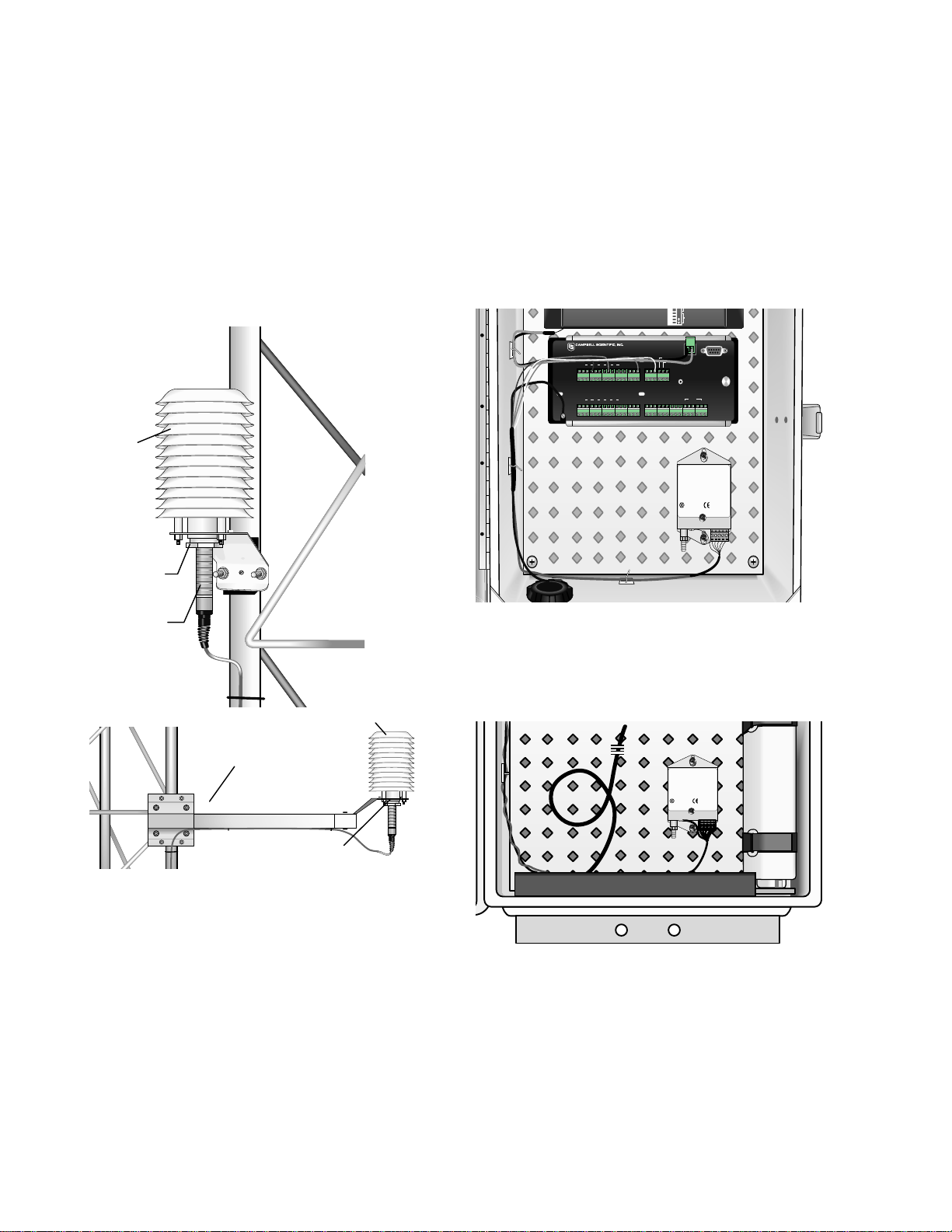
SECTION 4. SENSOR INSTALLATION
16-26 VDC OR AC RMS: POSITIVE TO
4.11 HMP45C/HMP35C VAISALA TEMPERATURE AND RH PROBE
Mount the probe inside the 41002 or UT12VA
12-Plate Gill Radiation shield as shown in
Figure
4.11-1.
1. Loosen the split plastic nut on the base of
the shield. Insert the probe and tighten the
nut.
41002
Split Nut
4.12 CS105 VAISALA BAROMETRIC PRESSURE SENSOR
Mount the CS105 sensor to the enclosure
backplate as shown in Figure 4.12-1 or Figure
4.12-2.
1. Mount the CS105 to the mounting plate
using the two screws and grommets
provided.
CHG
EITHER TERMINAL, NEGATIVE TO OTHER
+12
+12
POWER TO DATALOGGER OR
12V PERIPHERALS
G 12V
G 12V
SW 12V CTRL
POWER
SW 12V
IN
5V 5V G G
CR10X WIRING PANEL
MADE IN USA
SDM
P1 G P2 G C8 C7 C6 C5 C4 C3 C2 C1 G 12V12V
PRESSURE TRANSMITTER
MODEL
SERIAL NO
RANGE
OUTPUT
SUPPLY
VAISALA
MADE IN FINLAND
PTB100A
P4450003
800-1060 hPa
0-5 VDC
10-30 VDC
CS I/O
WIRING
PANEL NO.
EXT. TRIG
AGND
GND
SUPPLY
VOUT
EARTH
GROUND
Logan, Utah
SE
DIFF
G
SE
DIFF
G
78
4
GH L
AGH L AG H L AG E3 AG G G
12
1
GH L
AGH L AG H L AG E1 AG E2 G
910511 12
34256
MADE IN USA
6
3
HMP45C
UT018
HMP45C
FIGURE 4.11-1. HMP35C Vaisala
Temperature and RH Probe
UT12VA
FIGURE 4.12-1. CS105 Vaisala Barometric
Pressure Sensor in a
Standard Weather Station Enclosure
PRESSURE TRANSMITTER
PTB100A
MODEL
P4450003
SERIAL NO
800-1060 hPa
RANGE
0-5 VDC
OUTPUT
10-30 VDC
SUPPLY
VAISALA
MADE IN FINLAND
EXT. TRIG
AGND
GND
SUPPLY
VOUT
FIGURE 4.12-2. CS105MD Vaisala
Barometric Pressure Sensor in a
MetData1 Enclosure
4-6
Page 41

SECTION 4. SENSOR INSTALLATION
4.13 TEXAS ELECTRONICS TIPPING BUCKET RAIN GAGES (TE525, TE525WS, TE525MM)
1. Mount the rain gage to a vertical pipe as
shown in Figure 4.13-1. Mounting the gage
directly to the tripod or tower is not
recommended.
2. Dig a 6" diameter hole 24" deep.
3. Center a 1 1/4" to 2" IPS pipe in the hole
and fill the hole with concrete. Use a level
to plumb the pipe as the hole is filled.
4. After the concrete has cured, attach the rain
gage to the top of the pipe with the hose
clamps provided. Route the sensor lead to
the tripod in plastic or metal conduit.
4.14 CS700-L RAIN GAGE
The CS700-L should be mounted in a relatively
level spot that is representative of the
surrounding area. The lip of the funnel should
be horizontal and at least 30 inches above the
ground. The ground surface around the rain
gage should be natural vegetation or gravel.
The gage should not be installed over concrete
or pavement.
1. Mount the CS700 to either the CM100
(Figure 4.14-1) or a user supplied bracket.
Remove the CS700-L funnel from the base
by removing the three screws and lifting
upward. Adjust the three nuts on the
CM100 bracket to level the rain gage. On
user supplied brackets, shims or washers
can be used to level the rain gage. A
bubble level is mounted on the CS700-L
base to facilitate leveling.
2. Remove the rubber shipping band and
cardboard packing securing the tipping
bucket assembly. Tip the bucket several
times to insure the tipping mechanism is
moving freely.
TE525
Hose Clamp
(2) Places
FIGURE 4.13-1. TE525 Texas Electronics
Rain Gage
3. Replace the housing assembly and tighten
the three screws to secure the housing to
the base.
CS700
CM100
FIGURE 4.14-1. CS700-L Rain Gage and
CM100 Mounting Bracket
4-7
Page 42

SECTION 4. SENSOR INSTALLATION
4.15 SR50 SONIC RANGING SENSOR
The SR50s mounting stem enables various
installation options. A 3/4" x 1" NU-RAIL (CSI
part number 1049) enables the SR50 to mount
to a horizontal 3/4" pipe. The mounting stem
also has 1" pipe thread to accommodate other
threaded installation options. The UT018
crossarm and part number 6880 bracket can be
used to mount the SR50 to 3/4" - 1.25" diameter
vertical pipe.
The SR50 should be mounted perpendicular to
the target surface, without obstructions. See
Figure 4.15-1.
PN 1049
UT018
PN 6880
4.16 CS615 WATER CONTENT REFLECTOMETER
Probe rods can be inserted vertically or
horizontally into the soil surface, as shown in
Figure 4.16-1, or buried at any orientation to the
surface. A probe inserted vertically into a soil
surface will give an indication of the water
content in the upper 30 cm of soil. Horizontal
installation will detect the passing of wetting
fronts. Insertion at a 30 degree angle with the
surface will measure water content in the upper
15 cm of soil.
Probes must be inserted such that no air voids
are created around the rods, and that the rods
remain as parallel as possible. Use the
CS615G probe insertion guide to minimize
errors due to improper insertion.
The standard calibration for the CS615 probe,
as programmed in Short Cut, is valid for loamy
soils with low organic content. In other types of
SR50
soils, reporting the output in units of period will
make it possible to apply your own calibration
during post processing of data.
FIGURE 4.15-1. SR50 Sonic Ranging Sensor
1
2
FIGURE 4.16-1. CS615 Water Content
Reflectometer with
CS615G Probe Insertion Guide
4-8
Page 43

SECTION 4. SENSOR INSTALLATION
JARO
JARO
JARO
JARO
J
J
4.17 237 LEAF WETNESS SENSOR
Mounting and orientation considerations are left
to the user to determine. Consult the 237
manual for preparation and other information.
Normally, the sensor is mounted away from the
meteorological tower in or near a plant canopy.
FIGURE 4.17-1. 237 Leaf Wetness Sensor
4.18 257 SOIL MOISTURE SENSOR
1. Soak the sensor end of the 257 in irrigation
water for 12 to 14 hours. Allow the sensor
to dry for 1 to 2 days after soaking and
repeat the soak/dry cycle twice to improve
sensor response. Always install a wet
sensor.
2. Install the sensor into soil representative of
the field conditions you wish to monitor.
Avoid high or low spots. Placement south
of the weather station mast (northern
hemisphere) will avoid the effects of the
mast shade. Installation in the root zone is
best if measurements are used for irrigation
purposes.
3. The 257 should be removed from the soil
prior to harvest or cultivation operations to
avoid damaging the sensor or sensor cable.
Remove when soil is moist.
FIGURE 4.18-1. 257 Soil Moisture Sensor
4-9
Page 44

SECTION 4. SENSOR INSTALLATION
4.19 ENCLOSURE HUMIDITY SENSOR
Install the PN 10162, HM2000 Humidity Sensor
in the enclosure to monitor enclosure humidity.
The MetData1 and ET101/106 are shipped with
this sensor pre-installed.
site can be obtained from a USFA map, local
airport, or through a computer service offered by
the USFS called GEOMAG (Section 4.20.2). A
general map showing magnetic declination for the
contiguous United States is shown in Figure 4.20-1.
Declination angles east of True North are
considered negative, and are subtracted from 0
degrees to get True North as shown Figure 4.20-2.
Declination angles west of True North are considered positive, and are added to 0 degrees to get
True North as shown in Figure 4.20-3. For
example, the declination for Logan, Utah is 16°
East. True North is 360° - 16°, or 344° as read on
a compass.
Orientation is most easily done with two people,
one to aim and adjust the sensor, while the
other observes the wind direction displayed by
the datalogger.
1. Establish a reference point on the horizon for
True North.
2. Sighting down the instrument center line, aim
the nose cone, or counterweight at True North.
Display the input location for wind direction
using the *6 Mode of the datalogger, or, the
Monitor Mode of GraphTerm with an on-line
PC.
FIGURE 4.19-1. Enclosure Humidity Sensor
4.20 WIND DIRECTION SENSOR ORIENTATION
4.20.1 DETERMINING TRUE NORTH AND SENSOR ORIENTATION
Orientation of the wind direction sensor is done
after the datalogger has been programmed, and the
location of True North has been determined. True
North is usually found by reading a magnetic
compass and applying the correction for magnetic
declination*; where magnetic declination is the
number of degrees between True North and
Magnetic North. Magnetic declination for a specific
3. Loosen the band clamps or set screws that
secure the base of the sensor to the mast or
crossarm. While holding the vane position,
slowly rotate the sensor base until the
datalogger indicates 0 degrees. Tighten the
band clamps or set screws loosened
previously.
4. Engage the orientation ring indexing pin in
the notch at the instrument base (05103
and 05305 sensors only), and tighten the
band clamp on the orientation ring.
* Other methods employ observations using
the North Star or the sun, and are
discussed in the Quality Assurance
Handbook for Air Pollution Measurement
Systems, Volume IV - Meteorological
Measurements
4
.
4-10
Page 45

SECTION 4. SENSOR INSTALLATION
Subtract declination from 360° Add declination to 0°
22 E
20 E
18 E
16 E
14 E
FIGURE 4.20-1. Magnetic Declination for the Contiguous United States
4.20.2 PROMPTS FROM GEOMAG
GEOMAG is accessed by calling 1-800-3582663 with a computer and telephone modem,
and communications program such as
GraphTerm (PC208 Software). GEOMAG
prompts the caller for site latitude, longitude,
and elevation, which it uses to determine the
magnetic declination and annual change. The
following Menu and prompts are from
GEOMAG:
MAIN MENU
Type
Q for Quick Epicenter Determinations (QED)
L for Earthquake Lists (EQLIST)
M for Geomagnetic Field Values (GEOMAG)
X to log out
Enter program option: M
Would you like information on how to run
GEOMAG (Y/N)? N
Options:
1 = Field Values (D, I, H, X, Z, F)
2 = Magnetic Pole Positions
3 = Dipole Axis and Magnitude
4 = Magnetic Center [1] : 1
12 E
10 E
20 W
18 W
16 W
14 W
12 W
10 W
8 W
6 W
4 W
2 W
0
2 E
6 E
4 E
8 E
Latitude : 42/2 N
Longitude : 111/51/2 W
Elevation : 4454
Units (m/km/ft) : ft
Example of report generated by GEOMAG:
Model: USCON90 Latitude: 42/2 N
Date : 7/27/93 Longitude: 111/51/2 W
Elevation: 4454.0 ft
D
deg min
15 59.6
Annual change:
0 -6.1
The declination in the example above is listed
as 15 degrees and 59.6 minutes. Expressed in
degrees, this would be 15.99 degrees. As
shown in Figure 4.20-1, the declination for Utah
is east, so True North for this site is 360 - 15.99,
or 344 degrees. The annual change is -6.1
minutes.
Display values twice [N]: press return
Name of field model [USCON90]: press return
Date
[current date]:
press return
4-11
Page 46

SECTION 4. SENSOR INSTALLATION
FIGURE 4.20-2. Declination Angles East of
True North Are Subtracted From 0 to Get
True North
FIGURE 4.20-3. Declination Angles West of
True North Are Added to 0 to Get
True North
4-12
Page 47

SECTION 5. METDATA1 SOFTWARE INSTALLATION
Software required for the METDATA1 consists of the datalogger program and a datalogger support
software suite for Windows or MS-DOS.
5.1 DATALOGGER PROGRAM
The datalogger program operates the
MetData1. It programs the MetData1 to
measure sensors, process the measurements,
and store data in the datalogger’s memory. The
datalogger program is created using Short Cut
for MS-DOS. It is compatible with Windows
DOS emulator. A separate manual covers the
use of Short Cut in detail.
5.2 DATALOGGER SUPPORT SUITE
A datalogger support software suite, either
PC208W or PC208, enables interfacing with the
MetData1 through Windows or MS-DOS.
Follow the installation procedure outlined in the
front of the software manual. PC208(W) is
used to download programs to the MetData1. It
is also used to monitor data in real time and
retrieve data stored in the MetData1.
5.3 QUICK START REVIEW
Follow these steps to program the MetData1
and install the datalogger support software
suite.
File | Open | Station then RealTime | Call
then Tools | Clock Set / Check will activate
the station file and confirm communications
by checking the datalogger clock.
6) Download the program created in Step 2.
With PC208W Connect | Send will
download the MetData1 program. With
PC208 Tools | Send Datalogger Prog will
download the MetData1 program.
7) After the appropriate length of time, retrieve
data from the datalogger to an ASCII file.
With PC208W Connect | Collect will retrieve
data. With PC208 DataCollection |
Call Now (CurrentStn) will retrieve data.
8) Weather reports can be generated. PAR
files created by Short Cut can be used to
create simple reports. With PC208W
Report | File | Open will select a PAR file.
With PC208, File | Reports | Edit Param
File will select a PAR file.
1) Install PC208W or PC208, and Short Cut,
into your Windows or DOS computer.
2) Start Short Cut by entering “MetData1” at a
DOS prompt. Create the MetData1
program by following the four steps
outlined. Use CR10X as the datalogger
choice in Short Cuts Step 1.
3) Start PC208 by typing “PC208E” at the DOS
prompt OR start PC208W from Windows.
4) Create a station file with PC208 (File |
New | Station) OR create a station on the
PC208W device map (Setup |
Add Device).
5) Establish communications with the
MetData1. With PC208W Connect |
Connect will activate the communication
and confirm communications by reporting
the datalogger clock time. With PC208
5-1
Page 48

Page 49

SECTION 6. MAINTENANCE AND TROUBLESHOOTING
These guidelines apply to several different Campbell Scientific weather stations.
6.1 MAINTENANCE
Proper maintenance of weather station
components is essential to obtain accurate
data. Equipment must be in good operating
condition, which requires a program of regular
inspection and maintenance. Routine and
simple maintenance can be accomplished by
the person in charge of the weather station.
More difficult maintenance such as sensor
calibration, sensor performance testing (i.e.,
bearing torque), and sensor component
replacement, generally requires a skilled
technician, or that the instrument be sent to
Campbell Scientific or the manufacturer.
A station log should be maintained for each
weather station that includes serial numbers,
dates that the site was visited, and maintenance
that was performed.
6.1.1 INSTRUMENTATION MAINTENANCE
The instrumentation requires a minimum of
routine maintenance. A few preventative
maintenance steps will optimize battery life and
decrease the chances of datalogger failure.
6.1.2 BATTERIES
solar panel at all times. The charge indicating
diode should be "ON" when voltage to the
charging circuitry is present. Be aware of
battery voltage that consistently decreases over
time, which indicates a failure in the charging
circuitry.
6.1.3 DESICCANT
Enclosure humidity is monitored in the ET
Enclosure and MetData1 systems by an RH
chip incorporated into the connector board.
Change the desiccant packs when the
enclosure RH exceeds 35%. The RH chip
should be changed every 3 to 5 years.
In standard weather stations, a humidity
indicator card is provided with the enclosure. A
small RH sensor (10162) can be purchased
separately to record the RH inside the
enclosure. Change the desiccant when either
the card or the sensor read about 35% RH.
Desiccant may be ordered through Campbell
Scientific (DSC 20/4).
Desiccant packs inside of the dataloggers do not
require replacement under normal conditions.
Instruction 10 can be used to measure battery
voltage. By recording battery voltage the user
can determine how long a fresh set of batteries
will last (see the Installation Section of the
datalogger Operator's Manual for cold
temperature effects on alkaline batteries).
Short Cut and ETPro automatically program the
weather station to measure battery voltage.
When alkaline batteries are used, the battery
voltage should not be allowed to drop below 9.6
VDC before replacement. Where CR10 or 21X
dataloggers are used in the instrumentation, an
external battery must be used to maintain power
to the datalogger when changing batteries,
otherwise the clock, program, and data will be
lost (refer to the Installation Section of the
datalogger's Operator's Manual for details).
When not in use, remove the eight cells to
eliminate potential corrosion of the contact
points, and store in a cool dry place.
Rechargeable power supplies should be
connected to an AC transformer or unregulated
6.1.4 SENSOR MAINTENANCE
Sensor maintenance should be performed at
regular intervals, depending on the desired
accuracy and the conditions of use. A suggested
maintenance schedule is outlined below.
1 week
• Check the pyranometer for level and
contamination. Gently clean, if needed.
• Visually inspect the wind sensors and
radiation shield.
1 month
• Check the rain gage funnel for debris and
level.
• Do a visual/audio inspection of the
anemometer at low wind speeds.
• Check the filter of the temperature/humidity
sensor for contamination.
6-1
Page 50

SECTION 6. MAINTENANCE AND TROUBLESHOOTING
General Maintenance
• An occasional cleaning of the glass on the
solar panel will improve its efficiency.
• Check sensor leads and cables for
cracking, deterioration, proper routing, and
strain relief.
• Check the tripod or tower for structural
damage, proper alignment, and for
level/plumb.
6 months
Clean the temperature/humidity sensor.
•
• Clean the Gill Radiation Shield.
1 year
• Replace anemometer bearings.
• Calibrate the rain gage.
• Calibrate the HMP45C/HMP35C probe.
• Check calibration of CS500 RH Probe;
replace RH chip if necessary.
• Check internal RH chip (MetData1 and
ET101/106 only). Replace if >5% off.
2 years
• Calibrate the solar radiation sensors (some
users suggest yearly).
• Calibrate the temperature sensor.
• Replace the wind vane potentiometer and
bearings.
4 - 5 years
• Replace sensor cables as required.
6.2 TROUBLESHOOTING
6.2.1 NO RESPONSE USING THE KEYPAD
Check keypad response after each of the
following steps.
A. Make sure the battery has been installed,
and the power switch, if any, is "ON"
(Section 7).
B. Use a voltmeter to measure the voltage on
the 12 V and G terminals; the voltage must
be between 9.6 and 16 VDC.
C. Disconnect any sensor or peripheral wires
connected to the 5 V and 12 V terminals.
D. Disconnect any communications or storage
peripherals from the datalogger.
E. Reset the datalogger by turning the power
switch to "OFF", then to "ON" or
disconnecting and reconnecting the battery.
F. If still no response, call Campbell Scientific.
6.2.2 NO RESPONSE FROM DATALOGGER THROUGH SC32A OR MODEM PERIPHERAL
At the datalogger:
A. Make sure the battery has been installed, and
the power switch, if any, is "ON" (Section 7).
B. Use a voltmeter to measure the voltage on
the 12 V and G terminals; the voltage must
be between 9.6 and 16 V DC.
C. Make sure the datalogger is connected to
the modem, and the modem is properly
configured and cabled (Section 9).
At the computer:
D. Make sure the Station File is configured
correctly (PC208 Manual).
E. Check the cable(s) between the serial port
and the modem. If cables have not been
purchased through Campbell Scientific,
check for the following configuration using
an ohm meter:
25-pin serial port:
computer end modem end
22
33
77
20 20
9-pin serial port:
computer end modem end
23
32
420
57
F. Make sure the modem is properly
configured and cabled (Section 9).
G. If still no response, call Campbell Scientific.
6-2
Page 51

6.2.3 -99999 DISPLAYED IN AN INPUT LOCATION
A. Make sure the battery voltage is between
9.6 and 16 VDC.
B. With the MetData1 or ET106, verify that the
sensor is connected to the proper bulkhead
connector. With custom weather stations,
verify the sensor is wired to the analog
channel specified in the measurement
instruction or Short Cut .FSL file (singleended channels are not labeled on the older
silver-colored wiring panels and are
numbered sequentially starting at 1H; i.e. 1L
is single-ended channel 2).
C. Make sure the Range parameter in the
measurement instruction covers the full
scale voltage output by the sensor.
6.2.4 UNREASONABLE RESULTS DISPLAYED IN AN INPUT LOCATION
SECTION 6. MAINTENANCE AND TROUBLESHOOTING
A. Inspect the sensor for damage and/or
contamination.
B. Make sure the sensor is properly wired to
the datalogger.
C. Check the multiplier and offset parameters
in the measurement instruction.
6.2.5 6999 OR 99999 STORED IN FINAL STORAGE (OR STORAGE MODULE)
A. Final Storage format limitations exceeded
(any number larger than 6999 in low
resolution, or 99999 in high resolution
format is stored as the maximum number).
Change the datalogger program.
6-3
Page 52

Page 53

This is a blank page.
Page 54

Campbell Scientific Companies
Campbell Scientific, Inc. (CSI)
815 West 1800 North
Logan, Utah 84321
UNITED STATES
www.campbellsci.com
info@campbellsci.com
Campbell Scientific Africa Pty. Ltd. (CSAf)
PO Box 2450
Somerset West 7129
SOUTH AFRICA
www.csafrica.co.za
sales@csafrica.co.za
Campbell Scientific Australia Pty. Ltd. (CSA)
PO Box 444
Thuringowa Central
QLD 4812 AUSTRALIA
www.campbellsci.com.au
info@campbellsci.com.au
Campbell Scientific do Brazil Ltda. (CSB)
Rua Luisa Crapsi Orsi, 15 Butantã
CEP: 005543-000 São Paulo SP BRAZIL
www.campbellsci.com.br
suporte@campbellsci.com.br
Campbell Scientific Canada Corp. (CSC)
11564 - 149th Street NW
Edmonton, Alberta T5M 1W7
CANADA
www.campbellsci.ca
dataloggers@campbellsci.ca
Campbell Scientific Ltd. (CSL)
Campbell Park
80 Hathern Road
Shepshed, Loughborough LE12 9GX
UNITED KINGDOM
www.campbellsci.co.uk
sales@campbellsci.co.uk
Campbell Scientific Ltd. (France)
Miniparc du Verger - Bat. H
1, rue de Terre Neuve - Les Ulis
91967 COURTABOEUF CEDEX
FRANCE
www.campbellsci.fr
campbell.scientific@wanadoo.fr
Campbell Scientific Spain, S. L.
Psg. Font 14, local 8
08013 Barcelona
SPAIN
www.campbellsci.es
info@campbellsci.es
Please visit www.campbellsci.com to obtain contact information for your local US or International representative.
 Loading...