

Page 1

LoggerNet
Version 4.2
Revision: 7/13
Copyright © 1999-2013
Campbell Scientific, Inc.
Page 2

Page 3

License for Use
This software is protected by United States copyright law and international
copyright treaty provisions. The installation and use of this software constitutes
an agreement to abide by the provisions of this license agreement.
Campbell Scientific grants you a non-exclusive license to use this software in
accordance with the following:
(1) The purchase of this software allows you to install and use the software on
one computer only.
(2) This software cannot be loaded on a network server for the purposes of
distribution or for access to the software by multiple operators. If the
software can be used from any computer other than the computer on which
it is installed, you must license a copy of the software for each additional
computer from which the software may be accessed.
(3) If this copy of the software is an upgrade from a previous version, you
must possess a valid license for the earlier version of software. You may
continue to use the earlier copy of software only if the upgrade copy and
earlier version are installed and used on the same computer. The earlier
version of software may not be installed and used on a separate computer
or transferred to another party.
(4) This software package is licensed as a single product. Its component parts
may not be separated for use on more than one computer.
(5) You may make one (1) backup copy of this software onto media similar to
the original distribution, to protect your investment in the software in case
of damage or loss. This backup copy can be used only to replace an
unusable copy of the original installation media.
This software may not be sold, included or redistributed in any other software,
or altered in any way without prior written permission from Campbell
Scientific. All copyright notices and labeling must be left intact.
Page 4

Limited Warranty
The following warranties are in effect for ninety (90) days from the date of
shipment of the original purchase. These warranties are not extended by the
installation of upgrades or patches offered free of charge.
Campbell Scientific warrants that the installation media on which the software
is recorded and the documentation provided with it are free from physical
defects in materials and workmanship under normal use. The warranty does not
cover any installation media that has been damaged, lost, or abused. You are
urged to make a backup copy (as set forth above) and record the CD key to
protect your investment. Damaged or lost media is the sole responsibility of the
licensee and will not be replaced by Campbell Scientific.
Campbell Scientific warrants that the software itself will perform substantially
in accordance with the specifications set forth in the instruction manual when
properly installed and used in a manner consistent with the published
recommendations, including recommended system requirements. Campbell
Scientific does not warrant that the software will meet licensee’s requirements
for use, or that the software or documentation are error free, or that the
operation of the software will be uninterrupted.
Campbell Scientific will either replace or correct any software that does not
perform substantially according to the specifications set forth in the instruction
manual with a corrected copy of the software or corrective code. In the case of
significant error in the installation media or documentation, Campbell
Scientific will correct errors without charge by providing new media, addenda,
or substitute pages. If Campbell Scientific is unable to replace defective media
or documentation, or if it is unable to provide corrected software or corrected
documentation within a reasonable time, it will either replace the software with
a functionally similar program or refund the purchase price paid for the
software.
All warranties of merchantability and fitness for a particular purpose are
disclaimed and excluded. Campbell Scientific shall not in any case be liable for
special, incidental, consequential, indirect, or other similar damages even if
Campbell Scientific has been advised of the possibility of such damages.
Campbell Scientific is not responsible for any costs incurred as a result of lost
profits or revenue, loss of use of the software, loss of data, cost of re-creating
lost data, the cost of any substitute program, telecommunication access costs,
claims by any party other than licensee, or for other similar costs.
This warranty does not cover any software that has been altered or changed in
any way by anyone other than Campbell Scientific. Campbell Scientific is not
responsible for problems caused by computer hardware, computer operating
systems, or the use of Campbell Scientific’s software with non-Campbell
Scientific software.
Licensee’s sole and exclusive remedy is set forth in this limited warranty.
Campbell Scientific’s aggregate liability arising from or relating to this
agreement or the software or documentation (regardless of the form of action;
e.g., contract, tort, computer malpractice, fraud and/or otherwise) is limited to
the purchase price paid by the licensee.
Page 5

Table of Contents
PDF viewers: These page numbers refer to the printed version of this document. Use the
PDF reader bookmarks tab for links to specific sections.
Preface — What’s New in LoggerNet 4?...........................xv
1. System Requirements .............................................1-1
1.1 Hardware and Software.................................................................... 1-1
1.2 Configuration of TCP/IP Service ..................................................... 1-1
2. Installation, Operation and Backup Procedures...2-1
2.1 CD-ROM Installation....................................................................... 2-1
2.2 Upgrade Notes.................................................................................. 2-2
2.3 LoggerNet Operations and Backup Procedures ............................... 2-2
2.3.1 LoggerNet Directory Structure and File Descriptions............... 2-3
2.3.1.1 Program Directory.......................................................... 2-3
2.3.1.2 Working Directories....................................................... 2-3
2.3.2 Backing up the Network Map and Data Files ........................... 2-5
2.3.2.1 Performing a Manual Backup......................................... 2-5
2.3.2.2 Performing Scheduled Backups ..................................... 2-6
2.3.2.3 Performing Backups from the Task Master.................... 2-6
2.3.2.4 Restoring the Network from a Backup File.................... 2-7
2.3.3 Loss of Computer Power........................................................... 2-7
2.3.4 Program Crashes ....................................................................... 2-8
2.4 Installing/Running LoggerNet as a Service...................................... 2-8
2.4.1 Issues with Running LoggerNet as a Service............................ 2-9
2.4.1.1 Write Access .................................................................. 2-9
2.4.1.2 Network Drives ............................................................ 2-10
2.5 Special Note on Windows XP Service Pack 2 ............................... 2-10
3. Introduction..............................................................3-1
3.1 What is LoggerNet? ......................................................................... 3-1
3.1.1 What Next? ............................................................................... 3-1
3.2 Overview of Major LoggerNet Functions and Associated
Software Applications .................................................................. 3-2
3.2.1 The Heart of it All – LoggerNet Toolbar .................................. 3-2
3.2.1.1 Toolbar Views................................................................ 3-2
3.2.1.2 Favorites Category ......................................................... 3-3
3.2.1.3 Toolbar Menus ............................................................... 3-4
3.2.1.4 Command Line Arguments ............................................ 3-4
3.2.1.5 Alternate Language Support........................................... 3-5
3.2.2 LoggerNet Admin/LoggerNet Remote...................................... 3-6
3.2.3 Setting Up Datalogger Communication Networks.................... 3-6
3.2.4 Real Time Tools........................................................................ 3-7
3.2.5 Network Status and Problem Solving ....................................... 3-7
3.2.6 Network Management Tools..................................................... 3-8
3.2.7 Creating and Editing Datalogger Programs .............................. 3-8
3.2.8 Working with Data Files ........................................................... 3-9
i
Page 6

Table of Contents
3.2.9 Automating Tasks with Task Master....................................... 3-10
3.2.10 Managing External Data Storage Devices............................... 3-10
3.2.11 Optional Client Products Compatible with LoggerNet ...........3-10
3.2.11.1 LoggerNetData ............................................................. 3-10
3.2.11.2 Data Display Clients..................................................... 3-11
3.2.11.3 Baler ............................................................................. 3-11
3.2.11.4 CSIOPC Server (PC-OPC) ........................................... 3-11
3.2.11.5 Software Development Kit ........................................... 3-11
3.3 Getting Help for LoggerNet Applications ...................................... 3-11
4. Setting up Datalogger Networks............................ 4-1
4.1 Setup Screen – EZ View (EZSetup Wizard) ....................................4-1
4.2 Setup Screen — Standard View .......................................................4-3
4.2.1 Adding Devices to the Network ................................................ 4-4
4.2.2 Applying Changes, Undo and Redo ..........................................4-6
4.2.3 Renaming Network Devices...................................................... 4-7
4.2.4 Device Settings.......................................................................... 4-7
4.2.4.1 ComPort.......................................................................... 4-7
4.2.4.2 IPPort (Internet Protocol Serial Port).............................. 4-8
4.2.4.3 TAPIPort (Telephony API)............................................. 4-9
4.2.4.4 Datalogger .................................................................... 4-11
4.2.4.4.1 Hardware Tab .................................................... 4-11
4.2.4.4.2 Schedule Tab...................................................... 4-13
4.2.4.4.3 Final Storage Area 1 and 2 Tab (Edlog
Dataloggers with Mixed-array Operating
System)........................................................... 4-17
4.2.4.4.4 Data Files Tab (CRBasic Dataloggers, and
Edlog Dataloggers with Table Data and
PakBus Operating systems)............................ 4-18
4.2.4.4.5 Clock Tab........................................................... 4-21
4.2.4.4.6 Program Tab ...................................................... 4-22
4.2.4.4.7 File Retrieval Tab (CR1000, CR3000, CR800
Series, and Edlog Dataloggers with PakBus
Operating Systems) ........................................ 4-22
4.2.4.5 PhoneBase .................................................................... 4-23
4.2.4.6 PhoneRemote................................................................ 4-24
4.2.4.7 RFBase ......................................................................... 4-25
4.2.4.8 RFRemote..................................................................... 4-26
4.2.4.9 RFBase-TD................................................................... 4-27
4.2.4.10 RF RemoteTD .............................................................. 4-31
4.2.4.11 RFRemote-PB............................................................... 4-31
4.2.4.12 MD9 Base..................................................................... 4-32
4.2.4.13 MD9 Remote ................................................................ 4-34
4.2.4.14 RF400 ........................................................................... 4-35
4.2.4.15 RF400 Remote.............................................................. 4-36
4.2.4.16 Generic Modem............................................................ 4-38
4.2.4.17 PakBusPort ................................................................... 4-39
4.2.4.18 PakBus Router.............................................................. 4-42
4.2.4.19 PakBusPort HD ............................................................ 4-43
4.2.4.20 PakBusTcpServer ......................................................... 4-44
4.2.4.21 SerialPortPool............................................................... 4-46
4.2.4.22 TerminalPortPool..........................................................4-49
4.2.5 Setting Up Scheduled Data Collection .................................... 4-52
4.2.5.1 Data Collection Scheduling Considerations ................. 4-52
4.2.5.2 Intervals........................................................................ 4-53
ii
Page 7

Table of Contents
4.2.5.2.1 Datalogger Program Intervals............................ 4-53
4.2.5.2.2 Data Collection Setting Intervals....................... 4-53
4.2.5.2.3 Communications Path Considerations............... 4-54
4.2.5.3 Setting Up Scheduled Data Collection ......................... 4-54
4.2.6 Setting the Clock..................................................................... 4-56
4.2.7 Sending a Program to the Datalogger from Setup................... 4-57
4.2.8 Setup’s Tools Menu ................................................................ 4-57
4.2.8.1 LoggerNet Server Settings ........................................... 4-57
4.2.8.1.1 LoggerNet Settings............................................ 4-57
4.2.8.1.2 PakBus Settings ................................................. 4-58
4.2.8.1.3 LoggerNet Defaults ........................................... 4-58
4.2.8.1.4 IPManager Settings............................................ 4-58
4.2.8.1.4.1 Troubleshooting Tips ......................................... 4-59
4.2.8.2 Copy Device Settings ................................................... 4-59
4.2.8.3 Troubleshooter ............................................................. 4-60
4.2.9 Setup’s Backup Menu ............................................................. 4-60
4.2.10 Selecting a Remote Server ...................................................... 4-60
4.2.11 Selecting a View ..................................................................... 4-60
4.3 Network Planner............................................................................. 4-62
4.3.1 Functional Overview............................................................... 4-62
4.3.2 The Drawing Canvas............................................................... 4-62
4.3.2.1 Adding a Background Image........................................ 4-63
4.3.2.2 Scrolling the Drawing Canvas...................................... 4-63
4.3.2.3 Changing the Canvas Scale .......................................... 4-65
4.3.3 Adding Stations to the Network.............................................. 4-65
4.3.4 Adding Peripherals to a Station............................................... 4-65
4.3.5 Adding Stations Links............................................................. 4-66
4.3.6 Adding Activities .................................................................... 4-68
4.3.7 The Station Summary.............................................................. 4-71
4.3.8 Configuring Devices ............................................................... 4-72
4.3.8.1 Configuring Using the Device Configuration
Protocol..................................................................... 4-73
4.3.8.1.1 Avoiding Conflicts with the LoggerNet
Server ............................................................. 4-74
4.3.8.1.2 Settings Generated............................................. 4-75
4.3.8.2 Configuring a LoggerNet Server.................................. 4-75
4.3.9 Saving Your Work .................................................................. 4-78
4.3.10 Arranging Screen Components ............................................... 4-79
4.4 Device Configuration Utility.......................................................... 4-79
5. Real-Time Tools .......................................................5-1
5.1 The Connect Screen ......................................................................... 5-1
5.1.1 Connecting to the Datalogger — or Not ................................... 5-1
5.1.2 Data Collection ......................................................................... 5-3
5.1.2.1 Collect Now ................................................................... 5-3
5.1.2.2 Custom Collection.......................................................... 5-4
5.1.2.2.1 Mixed-array Dataloggers..................................... 5-4
5.1.2.2.2 Table-based Dataloggers ..................................... 5-5
5.1.3 Ports and Flags.......................................................................... 5-8
5.1.4 Datalogger Clock .................................................................... 5-10
5.1.5 Program Management ............................................................. 5-11
5.1.5.1 Sending a Datalogger Program..................................... 5-11
5.1.5.2 CR200 Series Programs................................................ 5-12
5.1.5.3 Retrieving Datalogger Programs.................................. 5-12
5.1.6 Program Association ............................................................... 5-12
iii
Page 8

Table of Contents
5.1.7 Data Displays .......................................................................... 5-13
5.1.7.1 Data Display Limitations.............................................. 5-14
5.1.7.2 Numeric Display Screens ............................................. 5-14
5.1.7.2.1 Adding and Removing Values........................... 5-15
5.1.7.2.2 Display Options ................................................. 5-17
5.1.7.2.3 Right Click Menu Options ................................. 5-18
5.1.7.3 Graphical Display Screens............................................ 5-18
5.1.7.3.1 Displaying Values on a Graph ........................... 5-19
5.1.7.3.2 Graph Options.................................................... 5-20
5.1.7.3.3 Trace Options..................................................... 5-25
5.1.7.3.4 Right Click Menu Options ................................. 5-26
5.1.7.3.5 Additional Capabilities ...................................... 5-28
5.1.8 Table Monitor.......................................................................... 5-28
5.1.9 File Control for CR5000, CR1000, CR800 Series, CR3000,
and CR9000 Dataloggers..................................................... 5-29
5.1.10 Terminal Emulator .................................................................. 5-33
5.1.11 Station Status........................................................................... 5-34
5.1.12 Calibration Wizard .................................................................. 5-35
5.2 Real-Time Monitoring and Control................................................ 5-36
5.2.1 Development Mode ................................................................. 5-36
5.2.1.1 The RTMC Workspace................................................. 5-37
5.2.1.2 Display Components..................................................... 5-38
5.2.1.3 Functions Available from the RTMC Menus ............... 5-39
5.2.1.4 Expressions................................................................... 5-44
5.2.1.4.1 Operators............................................................ 5-46
5.2.1.4.2 Order of Precedence........................................... 5-47
5.2.1.4.3 Predefined Constants ......................................... 5-47
5.2.1.4.4 Predefined Time Constants ................................ 5-47
5.2.1.4.5 Functions............................................................ 5-48
5.2.1.4.6 Logical Functions .............................................. 5-49
5.2.1.4.7 String Functions................................................. 5-50
5.2.1.4.8 Conversion Functions ........................................ 5-50
5.2.1.4.9 Time Functions .................................................. 5-51
5.2.1.4.10 Start Option Functions ....................................... 5-51
5.2.1.4.11 Statistical Functions........................................... 5-52
5.2.1.5 Remote Connection ...................................................... 5-53
5.2.2 RTMC Run-Time ....................................................................5-53
6. Network Status and Resolving Communication
Problems ............................................................... 6-1
6.1 Status Monitor .................................................................................. 6-1
6.2 LogTool.......................................................................................... 6-12
6.1.1 Visual Status Indicators............................................................. 6-2
6.1.2 Status Monitor Functions .......................................................... 6-3
6.1.2.1 Selecting Columns.......................................................... 6-3
6.1.2.2 Display/Subnet ............................................................... 6-8
6.1.2.3 Toggle Collection On/Off............................................... 6-8
6.1.2.4 Reset Device................................................................... 6-8
6.1.2.5 Collect Now/Stop Collection.......................................... 6-8
6.1.2.6 Pool Statistics ................................................................. 6-9
6.1.2.7 Pool Devices................................................................. 6-10
6.1.2.8 State of Operations ....................................................... 6-10
6.2.1 Log Types................................................................................ 6-13
6.2.2 Using LogTool ........................................................................ 6-13
iv
Page 9

Table of Contents
6.2.3 Saving Logs to File ................................................................. 6-14
6.3 Comm Test..................................................................................... 6-15
6.4 PakBus Graph ................................................................................ 6-16
6.4.1 Selecting the PakBus Network to View .................................. 6-17
6.4.2 Dynamic and Static Links ....................................................... 6-17
6.4.3 Viewing/Changing Settings in a PakBus Datalogger.............. 6-17
6.4.4 Right-Click Functionality ....................................................... 6-18
6.4.5 Discovering Probable Routes between Devices...................... 6-18
6.5 Troubleshooter ............................................................................... 6-18
6.5.1 Status Information................................................................... 6-19
6.5.2 Buttons.................................................................................... 6-20
6.5.3 Archiving Troubleshooter Results .......................................... 6-26
6.5.4 Other Tools in Troubleshooter................................................ 6-27
6.6 LoggerNet Server Monitor............................................................. 6-27
7. Creating and Editing Datalogger Programs ..........7-1
7.1 Review of CSI Datalogger Models .................................................. 7-1
7.2 Short Cut .......................................................................................... 7-2
7.2.1 Overview................................................................................... 7-2
7.2.2 Creating a Program Using Short Cut ........................................ 7-3
7.2.2.1 Step 1 – Create a New File or Open Existing File.......... 7-3
7.2.2.2 Step 2 – Select Datalogger and Specify Scan Interval ... 7-4
7.2.2.3 Step 3 – Choose Sensors to Monitor .............................. 7-7
7.2.2.4 Step 4 – Setup Output Tables ....................................... 7-14
7.2.2.5 Step 5 – Generate the Program in the Format
Required by the Datalogger...................................... 7-17
7.2.3 Short Cut Settings ................................................................... 7-18
7.2.3.1 Program Security.......................................................... 7-18
7.2.3.2 Datalogger ID............................................................... 7-18
7.2.3.3 Power-up Settings ........................................................ 7-18
7.2.3.4 Select CR200 Compiler................................................ 7-19
7.2.3.5 Sensor Support ............................................................. 7-19
7.2.3.6 Integration .................................................................... 7-20
7.2.3.7 Font .............................................................................. 7-20
7.2.3.8 Set Working Directory ................................................. 7-20
7.2.3.9 Enable Creation of Custom Sensor Files...................... 7-20
7.2.4 Editing Programs Created by Short Cut.................................. 7-20
7.2.5 New Sensor Files .................................................................... 7-21
7.2.6 Custom Sensor Files................................................................ 7-21
7.3 CRBasic Editor............................................................................... 7-21
7.3.1 Overview................................................................................. 7-21
7.3.2 Inserting Instructions............................................................... 7-22
7.3.2.1 Parameter Dialog Box .................................................. 7-22
7.3.2.2 Right-Click Functionality............................................. 7-24
7.3.3 Toolbar.................................................................................... 7-25
7.3.3.1 Compile........................................................................ 7-27
7.3.3.2 Compile, Save, and Send.............................................. 7-27
7.3.3.3 Conditional Compile and Save..................................... 7-31
7.3.3.4 Templates ..................................................................... 7-31
7.3.3.5 Program Navigation using BookMarks and GoTo ....... 7-32
7.3.3.6 CRBasic Editor File Menu ........................................... 7-32
7.3.3.7 CRBasic Editor Edit Menu........................................... 7-33
7.3.3.7.1 Other Options .................................................... 7-33
7.3.3.8 CRBasic Editor View Menu......................................... 7-33
7.3.3.8.1 Editor Preferences.............................................. 7-33
v
Page 10

Table of Contents
7.3.3.8.2 Instruction Panel Preferences............................. 7-35
7.3.3.8.3 Other Options..................................................... 7-35
7.3.3.9 CRBasic Editor Tools Menu......................................... 7-36
7.3.3.9.1 Edit Instruction Categories ................................ 7-36
7.3.3.9.2 Constant Customization..................................... 7-37
7.3.3.9.3 Other Options..................................................... 7-39
7.3.3.10 Available Help Information.......................................... 7-40
7.3.4 CRBasic Programming............................................................ 7-40
7.3.4.1 Programming Sequence................................................ 7-40
7.3.4.2 Program Declarations ................................................... 7-41
7.3.4.3 Mathematical Expressions............................................ 7-42
7.3.4.4 Measurement and Output Processing Instructions........ 7-42
7.3.4.5 Line Continuation......................................................... 7-43
7.3.4.6 Inserting Comments Into Program................................7-43
7.3.4.7 Example Program ......................................................... 7-44
7.3.4.8 Data Tables................................................................... 7-44
7.3.4.9 The Scan — Measurement Timing and Processing...... 7-46
7.3.4.10 Numerical Entries......................................................... 7-47
7.3.4.11 Logical Expression Evaluation..................................... 7-47
7.3.4.11.1 What is True?..................................................... 7-47
7.3.4.11.2 Expression Evaluation ....................................... 7-48
7.3.4.11.3 Numeric Results of Expression Evaluation........ 7-48
7.3.4.12 Flags ............................................................................. 7-49
7.3.4.13 Parameter Types ........................................................... 7-49
7.3.4.13.1 Expressions in Parameters .................................7-49
7.3.4.13.2 Arrays of Multipliers and Offsets for Sensor
Calibration...................................................... 7-50
7.3.4.14 Program Access to Data Tables.................................... 7-50
7.4 Edlog .............................................................................................. 7-51
7.4.1 Overview................................................................................. 7-51
7.4.1.1 Precompiler................................................................... 7-51
7.4.1.2 Context-sensitive Help ................................................. 7-52
7.4.1.3 Programming Efficiency............................................... 7-52
7.4.1.4 Input Location Labels................................................... 7-52
7.4.1.5 Final Storage Label Editor............................................ 7-52
7.4.1.6 Expression Compiler .................................................... 7-52
7.4.2 Creating a New Edlog Program............................................... 7-53
7.4.2.1 Program Structure......................................................... 7-54
7.4.2.2 Edlog File Types........................................................... 7-55
7.4.2.3 Inserting Instructions into the Program ........................7-56
7.4.2.4 Entering Parameters for the Instructions ......................7-57
7.4.2.5 Program Comments ...................................................... 7-57
7.4.2.6 Expressions................................................................... 7-58
7.4.2.7 Editing an Existing Program......................................... 7-63
7.4.2.8 Editing Comments, Instructions, and Expressions .......7-65
7.4.2.9 Cut, Copy, Paste, and Clipboard Options .....................7-65
7.4.3 Library Files ............................................................................ 7-65
7.4.4 Documenting a DLD File........................................................ 7-65
7.4.5 Display Options....................................................................... 7-66
7.4.5.1 Graphical Toolbar......................................................... 7-66
7.4.5.2 Renumbering the Instructions....................................... 7-67
7.4.5.3 Compress VIEW........................................................... 7-67
7.4.5.4 Indention....................................................................... 7-67
7.4.6 Input Locations........................................................................ 7-67
7.4.7 Entering Input Locations ......................................................... 7-68
7.4.8 Repetitions............................................................................... 7-68
vi
Page 11

Table of Contents
7.4.9 Input Location Editor .............................................................. 7-69
7.4.10 Input Location Anomalies....................................................... 7-70
7.4.11 Final Storage Labels................................................................ 7-71
7.4.12 Datalogger Settings Stored in the DLD File ........................... 7-73
7.4.13 Program Security .................................................................... 7-73
7.4.13.1 Setting Passwords in the DLD...................................... 7-73
7.4.13.2 Disabling Passwords .................................................... 7-73
7.4.14 Final Storage Area 2 ............................................................... 7-74
7.4.15 DLD File Labels ..................................................................... 7-74
7.4.15.1 Mixed-array Dataloggers.............................................. 7-74
7.4.15.2 Table-Based Dataloggers ............................................. 7-74
7.4.16 Power Up Settings/Compile Settings...................................... 7-75
7.4.17 Datalogger Serial Port Settings ............................................... 7-75
7.4.18 PakBus Settings ...................................................................... 7-76
7.4.18.1 Network........................................................................ 7-76
7.4.18.2 Beacon Intervals........................................................... 7-76
7.4.18.3 Neighbor Filter ............................................................. 7-77
7.4.18.4 Allocate General Purpose File Memory....................... 7-77
7.5 Transformer Utility ........................................................................ 7-77
7.5.1 Transforming a File................................................................. 7-77
7.5.2 Controls................................................................................... 7-79
8. Working with Data Files on the PC.........................8-1
8.1 View Pro .......................................................................................... 8-1
8.1.1 Overview................................................................................... 8-1
8.1.2 The Toolbar............................................................................... 8-2
8.1.3 Opening a File........................................................................... 8-4
8.1.3.1 Opening a Data File........................................................ 8-4
8.1.3.2 Opening Other Types of Files ........................................ 8-4
8.1.3.3 Opening a File in Hexadecimal Format.......................... 8-4
8.1.4 Viewing a LoggerNet Database Table ...................................... 8-4
8.1.4.1 Selecting a Database....................................................... 8-4
8.1.4.2 Selecting a Table ............................................................ 8-8
8.1.5 Importing a CSV File................................................................ 8-8
8.1.6 Data View ............................................................................... 8-11
8.1.6.1 Column Size ................................................................. 8-12
8.1.6.2 Header Information ...................................................... 8-12
8.1.6.3 Locking the TimeStamp Column ................................. 8-12
8.1.6.4 File Information............................................................ 8-12
8.1.6.5 Background Color ........................................................ 8-12
8.1.6.6 Font .............................................................................. 8-12
8.1.6.7 Window Arrangement .................................................. 8-13
8.1.7 Graphs..................................................................................... 8-13
8.1.7.1 Line Graph ................................................................... 8-15
8.1.7.1.1 Selecting Data to be Graphed ............................ 8-15
8.1.7.1.2 Graph Width ...................................................... 8-16
8.1.7.1.3 Scrolling ............................................................ 8-16
8.1.7.1.4 Graph Cursor ..................................................... 8-16
8.1.7.1.5 Line Graph Toolbar ........................................... 8-17
8.1.7.2 Histogram..................................................................... 8-19
8.1.7.2.1 Selecting Data to be Viewed.............................. 8-20
8.1.7.2.2 Options .............................................................. 8-21
8.1.7.2.3 Histogram Toolbar............................................. 8-21
vii
Page 12

Table of Contents
8.1.7.3 XY Plot......................................................................... 8-22
8.1.7.3.1 Selecting Data to be Plotted............................... 8-23
8.1.7.3.2 XY Plot Toolbar................................................. 8-23
8.1.7.4 Rainflow Histogram ..................................................... 8-24
8.1.7.4.1 Selecting Data to be View.................................. 8-25
8.1.7.4.2 Options............................................................... 8-26
8.1.7.4.3 Rainflow Histogram Toolbar ............................. 8-26
8.1.7.5 FFT ............................................................................... 8-27
8.1.7.5.1 Selecting Data to be Graphed............................. 8-28
8.1.7.5.2 Options............................................................... 8-29
8.1.7.5.3 FFT Toolbar....................................................... 8-29
8.1.8 Right-click-Menus................................................................... 8-30
8.1.8.1 Data View..................................................................... 8-30
8.1.8.2 Graphs .......................................................................... 8-32
8.1.8.3 Traces ...........................................................................8-32
8.1.9 Printing Options ...................................................................... 8-32
8.1.9.1 Print Setup .................................................................... 8-32
8.1.9.2 Printing Text................................................................. 8-33
8.1.9.3 Printing Graphs............................................................. 8-33
8.1.10 View Pro Online Help ............................................................. 8-33
8.1.11 Assigning Data Files to View.................................................. 8-33
8.2 Split ................................................................................................ 8-33
8.2.1 Functional Overview ............................................................... 8-33
8.2.2 Getting Started......................................................................... 8-34
8.2.3 Split Parameter File Entries..................................................... 8-40
8.2.3.1 Input Files..................................................................... 8-40
8.2.3.1.1 File Info ............................................................. 8-42
8.2.3.1.2 File Offset/Options ............................................ 8-42
8.2.3.1.3 Start Condition ................................................... 8-46
8.2.3.1.4 Stop Condition ...................................................8-49
8.2.3.1.5 Copy................................................................... 8-52
8.2.3.1.6 Select.................................................................. 8-53
8.2.3.1.7 Ranges................................................................ 8-54
8.2.3.1.8 Variables............................................................ 8-55
8.2.3.1.9 Numerical Limitations ....................................... 8-55
8.2.3.1.10 Mathematical Functions, Details, and
Examples........................................................ 8-56
8.2.3.1.11 Time Series Functions, Details, and Examples.. 8-58
8.2.3.1.12 Special Functions, Details, and Examples ......... 8-63
8.2.3.1.13 Split Functions Example .................................... 8-68
8.2.3.1.14 Summary of Select Line Syntax Rules ..............8-70
8.2.3.1.15 Time Synchronization........................................ 8-71
8.2.3.2 Output Files .................................................................. 8-74
8.2.3.2.1 Description of Output Option Commands .........8-75
8.2.3.2.2 Report Headings ................................................ 8-80
8.2.3.2.3 Column Headings .............................................. 8-80
8.2.4 Help Option ............................................................................. 8-80
8.2.5 Editing Commands.................................................................. 8-81
8.2.6 Running Split From a Command Line .................................... 8-81
8.2.6.1 Splitr Command Line Switches .................................... 8-81
8.2.6.1.1 Closing the Splitr.exe Program After
Execution (/R or /Q Switch)........................... 8-81
8.2.6.1.2 Running Splitr in a Hidden or Minimized
State (/H Switch) ............................................ 8-81
8.2.6.1.3 Running Multiple Copies of Splitr (/M Switch) 8-82
8.2.6.2 Using Splitr.exe in Batch Files .....................................8-82
viii
Page 13

Table of Contents
8.2.6.3 Processing Alternate Files ............................................ 8-82
8.2.6.3.1 Input/Output File Command Line Switches for
Processing Alternate Files.............................. 8-83
8.2.6.4 Processing Multiple Parameter Files with One
Command Line ......................................................... 8-86
8.2.7 Log Files ................................................................................. 8-86
8.3 CardConvert................................................................................... 8-86
8.3.1 Input/Output File Settings ....................................................... 8-87
8.3.2 Destination File Options ......................................................... 8-87
8.3.2.1 File Format ................................................................... 8-88
8.3.2.2 File Processing ............................................................. 8-88
8.3.2.3 File Naming.................................................................. 8-89
8.3.2.4 TOA5/TOB1 Format .................................................... 8-90
8.3.3 Converting the File.................................................................. 8-90
8.3.3.1 Repairing/Converting Corrupted Files ......................... 8-90
8.3.4 Viewing a Converted File ....................................................... 8-91
8.3.5 Running CardConvert From a Command Line ....................... 8-91
9. Automating Tasks with Task Master......................9-1
9.1 Task Master...................................................................................... 9-1
9.1.1 Setup Tab .................................................................................. 9-2
9.1.1.1 Adding Tasks.................................................................. 9-2
9.1.1.2 Logger Event Tasks........................................................ 9-3
9.1.1.3 Scheduled Event Tasks................................................... 9-5
9.1.1.3.1 Interval Tasks ...................................................... 9-5
9.1.1.3.2 Calendar............................................................... 9-6
9.1.1.4 Define What the Task Does............................................ 9-8
9.1.2 Status Tab................................................................................ 9-13
9.1.3 Remote Administration of the Task Master ............................ 9-15
9.1.4 Task Master Logs.................................................................... 9-15
10. Utilities Installed with LoggerNet .........................10-1
10.1 Device Configuration Utility.......................................................... 10-1
10.1.1 Overview................................................................................. 10-1
10.1.2 Main DevConfig Screen.......................................................... 10-2
10.1.3 Downloading an Operating System ........................................ 10-3
10.1.4 Terminal Tab........................................................................... 10-5
10.1.5 The Unknown Device Type .................................................... 10-5
10.1.6 Off-line Mode ......................................................................... 10-6
10.2 CoraScript ...................................................................................... 10-7
10.2.1 CoraScript Fundamentals........................................................ 10-7
10.2.2 Useful CoraScript Operations ................................................. 10-7
10.2.2.1 Connecting to the LoggerNet Server............................ 10-8
10.2.2.2 Checking and Setting Device Settings ......................... 10-8
10.2.2.3 Creating and using a Network Backup File.................. 10-8
10.2.2.4 Hole Management ........................................................ 10-9
10.2.2.5 Scripting CoraScript Commands................................ 10-10
10.3 RWIS Administrator .................................................................... 10-10
10.3.1 Overview............................................................................... 10-10
10.3.2 Adding a New RWIS Station................................................ 10-11
10.3.3 Editing Station Settings......................................................... 10-12
10.3.3.1 Station Communication Settings ................................ 10-12
10.3.3.2 Schedule Settings ....................................................... 10-13
10.3.3.3 Snapshots Settings...................................................... 10-15
ix
Page 14

Table of Contents
10.3.3.4 Clock Settings............................................................. 10-16
10.3.3.5 Data Tab .....................................................................10-18
10.3.4 Deleting a Station .................................................................. 10-18
10.3.5 Organization of RWIS Data in LoggerNet............................ 10-18
10.4 File Format Convert .....................................................................10-19
10.4.1 Overview............................................................................... 10-19
10.4.2 Options .................................................................................. 10-20
10.5 Toa_to_tob1.................................................................................. 10-22
11. Utilities Installed with LoggerNet Admin and
LoggerNet Remote.............................................. 11-1
11.1 Security Manager ........................................................................... 11-1
11.1.1 Initial Configuration of Security Manager ..............................11-1
11.1.2 Managing User Accounts ........................................................ 11-2
11.1.3 Resetting Security ................................................................... 11-5
11.1.4 Remote Task Management...................................................... 11-5
11.2 Hole Monitor .................................................................................. 11-5
11.2.1 Hole Collection Activity ......................................................... 11-6
11.2.2 Message Log ...........................................................................11-7
11.3 Data Filer........................................................................................ 11-8
11.3.1 Data Filer Requirements.......................................................... 11-8
11.3.2 Using the Data Filer ................................................................ 11-8
11.3.2.1 Connecting to a Computer Running the LoggerNet
Server Software......................................................... 11-8
11.3.2.1.1 Setting Up the Data Filer ...................................11-9
11.3.2.2 Collection Options........................................................ 11-9
11.3.3 The Collected Data................................................................ 11-11
11.3.4 Determining the Data Available in the Data Cache............... 11-11
11.3.5 Record Number Anomalies................................................... 11-12
11.3.6 Communication Status ..........................................................11-12
11.4 Data Export................................................................................... 11-12
11.4.1 Functional Overview ............................................................. 11-12
11.4.2 Theory of Operation .............................................................. 11-14
11.4.3 Custom Data Retrieval Client................................................ 11-15
11.4.4 Custom Client/Data Export Interface Description................. 11-15
11.4.5 RTMS Format Description.................................................... 11-20
11.4.6 Standard Format Description................................................. 11-21
12. Optional Client Applications Available for
LoggerNet............................................................ 12-1
12.1 Allowing Remote Connections to the LoggerNet Server ............... 12-1
12.2 LoggerNetData ............................................................................... 12-1
12.3 RTMC Run-Time ........................................................................... 12-2
12.4 RTMC Pro ...................................................................................... 12-2
12.5 LNDB............................................................................................. 12-2
12.6 Baler ............................................................................................... 12-2
12.7 CSIOPC Server (PC-OPC)............................................................. 12-3
12.8 Software Development Kit............................................................. 12-3
x
Page 15

Table of Contents
13. Implementing Advanced Communications
Links .....................................................................13-1
13.1 Phone to RF.................................................................................... 13-1
13.1.1 Setup ....................................................................................... 13-1
13.1.2 Operational Considerations..................................................... 13-2
13.1.2.1 Scheduled Data Collection ........................................... 13-2
13.1.2.2 Extra Response Time.................................................... 13-2
13.1.2.3 RF Address................................................................... 13-2
13.1.2.4 Max Time Online ......................................................... 13-2
13.1.3 Attaching a Datalogger to the RF Base................................... 13-2
13.1.3.1 Hardware Setup............................................................ 13-3
13.1.3.2 Network Setup in LoggerNet ....................................... 13-3
13.2 Phone to MD9 ................................................................................ 13-3
13.2.1 Setup ....................................................................................... 13-3
13.2.2 Operational Considerations..................................................... 13-4
13.2.2.1 Scheduled Data Collection ........................................... 13-4
13.2.2.2 MD9 Addresses............................................................ 13-4
13.2.2.3 Extra Response Time.................................................... 13-4
13.2.2.4 Max Time Online ......................................................... 13-4
13.2.2.5 1Grounding .................................................................. 13-5
13.3 TCP/IP to RF.................................................................................. 13-5
13.3.1 Setup ....................................................................................... 13-5
13.3.2 Operational Considerations..................................................... 13-5
13.3.3 Special Considerations............................................................ 13-6
14. Troubleshooting Guide .........................................14-1
14.1 What’s Changed? ........................................................................... 14-1
14.2 LoggerNet Server Problems........................................................... 14-1
14.2.1 Starting LoggerNet and Connecting to the Server .................. 14-1
14.2.2 Socket Errors........................................................................... 14-2
14.2.3 Data Collection Issues............................................................. 14-4
14.3 Application Screen Problems......................................................... 14-4
14.4 General Communication Link Problems........................................ 14-4
14.5 Terminal Emulator to Test Communications ................................. 14-5
14.6 RF Communication Link Issues..................................................... 14-8
14.6.1 Checking RF Components and Connections........................... 14-9
14.6.2 RF Signal Strength Testing ..................................................... 14-9
14.6.3 Troubleshooting with Attenuation Pads................................ 14-11
14.7 Using Data Table Monitor............................................................ 14-13
14.8 Troubleshooting PakBus Communications.................................. 14-17
Appendices
A. Glossary of Terms .................................................. A-1
B. Campbell Scientific File Formats .......................... B-1
B.1 PC File Data Formats.......................................................................B-1
B.1.1 Comma Separated .....................................................................B-1
B.1.2 ASCII Printable.........................................................................B-2
xi
Page 16

Table of Contents
B.1.3 TOACI1.................................................................................... B-2
B.1.3.1 Field Name Suffixes ...................................................... B-3
B.1.4 TOA5........................................................................................ B-4
B.1.5 TOB1........................................................................................ B-4
B.1.6 Array Compatible CSV ............................................................ B-6
B.1.7 CSIXML................................................................................... B-6
B.1.7.1 A Short Introduction to XML........................................ B-6
B.1.7.2 File Syntax..................................................................... B-8
B.1.7.3 The csixml Element..................................................... B-10
B.1.7.3.1 The head Element ................................................ B-11
B.1.7.3.2 The data Element ................................................. B-12
B.1.7.4 File Example................................................................ B-13
B.1.8 CSIJSON................................................................................ B-14
B.1.8.1 A Short Introduction to JSON ..................................... B-15
B.1.8.2 File Syntax................................................................... B-15
B.1.8.2.1 The head Object ................................................... B-15
B.1.8.2.2 The data Array ..................................................... B-18
B.1.8.3 File Example................................................................ B-18
B.2 Datalogger Data Formats............................................................... B-19
B.2.1 TOB2 or TOB3....................................................................... B-19
B.3 Binary Data Value Types .............................................................. B-21
B.3.1 FP2 (2 Byte Low Resolution Format) .................................... B-21
B.3.2 FP4 (4 Byte High Resolution Format).................................... B-21
B.3.3 IEEE4 ..................................................................................... B-21
B.3.4 IEEE8 ..................................................................................... B-21
B.4 Converting Binary File Formats.................................................... B-22
B.4.1 Split ........................................................................................ B-22
B.4.2 View Pro................................................................................. B-22
B.4.3 CardConvert ........................................................................... B-22
B.4.4 File Format Convert ............................................................... B-22
B.4.5 TOB32.EXE........................................................................... B-23
B.5 RTMS Format Description............................................................ B-23
C. Table-Based Dataloggers .......................................C-1
C.1 Memory Allocation for Final Storage.............................................. C-1
C.1.1 CR10X-TD Family Table-Based Dataloggers ......................... C-1
C.1.2 CR5000/CR1000/CR3000/CR800/CR9000 Memory for
Programs and Data Storage................................................... C-2
C.1.3 CR200 Series Dataloggers........................................................ C-2
C.2 Converting an Array-Based Program to a CR10X-TD Table-
Based Program using Edlog......................................................... C-3
C.2.1 Steps for Program Conversion ................................................. C-3
C.2.2 Program Instruction Changes ................................................... C-4
C.3 Table Data Overview....................................................................... C-5
C.4 Default Tables ................................................................................. C-6
D. Software Organization ............................................D-1
D.1 LoggerNet/Client Architecture ........................................................ D-1
D.2 LoggerNet Server Data Cache......................................................... D-1
D.2.1 Organization............................................................................. D-1
D.2.2 Operation.................................................................................. D-1
D.2.3 Retrieving Data from the Cache............................................... D-2
D.2.4 Updating Table Definitions...................................................... D-2
xii
Page 17

Table of Contents
D.3 Directory Organization.................................................................... D-3
D.3.1 C:\CampbellSci Directory (Working Directory)...................... D-3
D.3.2 C:\Program Files\CampbellSci\LoggerNet Directory
(Program File Directory) ...................................................... D-4
E. Log Files .................................................................. E-1
E.1 Event Logging..................................................................................E-1
E.1.1 Log Categories .......................................................................... E-1
E.1.2 Enabling Log Files.................................................................... E-2
E.1.3 Log File Message Formats ........................................................ E-2
E.1.3.1 General File Format Information....................................E-2
E.1.3.2 Transaction Log Format ................................................. E-3
E.1.3.3 Communications Status Log Format............................ E-18
E.1.3.4 Object State Log Format ..............................................E-21
E.2 CQR Log (RF Link) ....................................................................... E-22
F. Calibration and Zeroing.......................................... F-1
F.1 Calibration Essentials....................................................................... F-1
F.1.1 Definition of Calibration........................................................... F-1
F.1.2 Basic Calibration Process.......................................................... F-1
F.2 Writing Calibration Programs with the CRBasic Editor .................. F-2
F.2.1 The FieldCal Instruction ........................................................... F-2
F.2.2 Calibration File Details ............................................................. F-3
F.3 Four Kinds of Calibration ................................................................ F-3
F.3.1 Zeroing...................................................................................... F-3
F.3.2 Offset Calibration...................................................................... F-4
F.3.3 Two-Point Multiplier and Offset Calibration............................ F-4
F.3.4 Two-Point Multiplier Only Calibration..................................... F-5
F.4 Performing a Manual Calibration..................................................... F-5
F.4.1 How to Use the Mode Variable for Calibration Status and
Control................................................................................... F-5
F.4.2 Using the Mode Variable for Manual Single-Point
Calibration............................................................................. F-6
F.4.3 Using the Mode Variable for Manual Two-Point
Calibration............................................................................. F-7
F.5 Using the Calibration Wizard with Running Programs.................... F-8
F.5.1 Calibration Wizard Basic Operation .........................................F-8
F.5.2 Using the Wizard to Perform Two-Point Multiplier and
Offset Calibrations ................................................................ F-8
F.5.3 Using the Wizard to Perform Zeroing Calibrations ................ F-12
F.5.4 Using the Wizard to Perform Offset Calibrations................... F-13
F.6 Strain and Shunt Calibration .......................................................... F-15
G. Importing Files into Excel ...................................... G-1
Tables
G.1 Array-Based Data File Import......................................................... G-1
G.2 Table-Based Data File Import......................................................... G-4
7-1. Formats for Output Data ................................................................ 7-46
7-2. Formats for Entering Numbers in CRBasic.................................... 7-47
7-3. Synonyms for True and False......................................................... 7-48
7-4. Rules for Names............................................................................. 7-49
xiii
Page 18

Table of Contents
7-5. Operators and Functions................................................................. 7-59
7-6. Editor Keystrokes ........................................................................... 7-64
8-1. Comma Separated, Field Formatted, Printable ASCII, and
Table Oriented ASCII Input File Format Types ......................... 8-41
8-2. Example of Event Driven Test Data Set......................................... 8-50
8-3. Processed Data File Using Option C .............................................. 8-51
8-4. Input File Entries to Process the First Data Point for each Test ..... 8-52
8-5. Effects of Out of Range Values for Given Output Options ............ 8-54
8-6. Split Operators and Math Functions ............................................... 8-56
8-7. Time Series Functions .................................................................... 8-58
8-8. Split SPECIAL FUNCTIONS........................................................ 8-63
8-9. Definition of Blank or Bad Data for each Data File Format...........8-77
11-1. Security Manager Access Table ..................................................... 11-3
14-1. Socket Error Messages ................................................................... 14-3
B-1. Output Instruction Suffixes ............................................................. B-3
B-2. Pre-Defined XML Entities .............................................................. B-7
B-3. Field Data Types ........................................................................... B-12
C-1. Example of Status Table Entries (CR10T)...................................... C-7
E-1. Transaction Log Messages ...............................................................E-3
E-2. Communication Status Log Messages............................................E-19
F-1. The FieldCal Instruction “Family”................................................... F-2
xiv
Page 19

Preface — What’s New in LoggerNet 4?
Product History
LoggerNet 4 continues the original design of client-server functionality that
first appeared when Version 1.0 was released for Windows to replace Real
Time Monitoring Software (RTMS) that ran on OS/2 operating systems.
Versions in the 1.x series supported only table-based dataloggers and provided
large network users with sophisticated capabilities to develop clients to the
server to move data without having to store it in interim files.
Version 2.0 added support for dataloggers with mixed-array operating systems,
the CRBasic dataloggers, and additional communications devices. It also
supported client applications’ requests for data via TCP/IP, and automatically
created files on the PC for final storage data. Subsequent revisions in the 2.x
series added support for hardware as it was released and refined the clientserver architecture to make it more robust and flexible. Software development
kits and standalone clients were released to provide additional functionality.
NOTE
One of the main efforts in the development of LoggerNet 3.1 was to
incorporate support for the CR1000 datalogger. This included datalogger
management (connect, collect data, set clock, send program, etc.) in
LoggerNet, as well as programming support in CRBasic and Short Cut. To
help with creating CR1000 programs, a Transformer utility was developed to
convert existing CR10X Edlog programs to CR1000 CRBasic programs.
LoggerNet 3.2 added support for our new CR3000 datalogger. In addition,
LoggerNet Admin and LoggerNet Remote were developed, which provide
tools to support larger networks. These tools include security and remote
management capabilities, and the ability to run LoggerNet as a service.
LoggerNet 3.3 added support for the CR800 datalogger. A new file output
option was also added for table-based dataloggers. This CSV file format
option allows the creation of data files similar to those from mixed array
dataloggers.
LoggerNet 3.4 improved LoggerNet’s performance on Windows Vista. In
addition, changes were made to the user interface of the Numeric Display and
Graphs.
Beginning with LoggerNet 3.4, Windows NT is no longer
supported.
LoggerNet 4.0 introduces a new look and feel to the LoggerNet Toolbar.
Applications are divided into categories to make navigating the Toolbar easier.
You can also organize a Favorites category for the applications that you use
most often. A new file viewing application, View Pro, is introduced which
allows multiple data files to be opened, multiple graphs to be created, and
graphing in a variety of formats (Line Graph, X-Y Plot, Histogram, Rainflow
Histogram, and FFT). Another new application, the Network Planner, is
included. This is a graphical application that assists the user in designing
xv
Page 20

Preface — What’s New in LoggerNet 4?
PakBus datalogger networks. It allows the development of a model of the
PakBus network, proposes and verifies valid connections between devices, and
allows integration of the model directly into LoggerNet 4.0.
See below for more details on what is new in LoggerNet 4.0 and each
individual application.
One of the main efforts in the development of LoggerNet 4.1 was the ability to
use LNDB databases with View Pro. The ability to lock the timestamp column
on the left of the data file has also been added to View Pro. This keeps the
timestamp visible as you scroll through columns of data. The Device
Configuration Utility adds an off-line mode which allows you to look at the
settings for a certain device type without actually being connected to a device.
The CRBasic Editor now has the capability to open a read-only copy of any
file. This gives you the ability to open multiple copies of a program and
examine multiple areas of a very large program at the same time. You can also
now continue an instruction onto multiple lines by placing the line continuation
indicator (a single space followed by an underscore “_”) at the end of the each
line that is to be continued. Also, bookmarks in a CRBasic program are now
persistent from session to session. In the Troubleshooter and the Setup Screen
(Standard View), you can now click on a potential problem to bring up a menu
that allows you to go the Setup Screen or Status Monitor to fix the potential
problem, bring up help describing the problem, or in some cases fix the
problem directly. Campbell Scientific’s new wireless sensors have been added
to the Network Planner. An option to provide feedback on LoggerNet is now
available from the LoggerNet Toolbar’s Help menu.
NOTE
Beginning with LoggerNet 4.1, Windows 2000 is no longer
supported.
LoggerNet 4.2 adds support for IPv6 addresses. IPv6 addresses are written as
eight two-byte address blocks separated by colons and surrounded by brackets
(e.g., [2620:24:8080:8600:85a1:fcf2:2172:11bf]). Prior to LoggerNet 4.2, only
IPv4 addresses were supported. IPv4 addresses are written in dotted decimal
notation (e.g., 192.168.11.197). Leading zeroes are stripped for both IPv4 and
IPv6 addresses. Note that while LoggerNet now supports IPv6 addresses and
they can be used to specify servers, CR1000/CR3000/CR800 series dataloggers
will not support IPv6 until a future OS release. Check the OS revision history
on our website to determine when IPv6 support is added to the OS.
LoggerNet now supports display and input of Unicode characters/strings in
many areas of the product. Unicode is a universal system for encoding
characters. It allows LoggerNet to display characters in the same way across
multiple languages and countries. See Unicode in the LoggerNet help file index
for more information on Unicode and what applications support Unicode
characters. To support Unicode, an Insert Symbol dialog box has been added to
the CRBasic Editor. This allows you to insert Unicode symbols into your
CRBasic program for use in Strings and Units declarations.
The ability to set up subnets of the network map has been added to LoggerNet
Admin. The Setup Screen’s View | Configure Subnets menu item is used to
configure the subnets. Within each subnet, you can also specify groups of
dataloggers. The datalogger groups create folders than can be collapsed or
expanded when viewing the subnet. Once subnets have been configured, you
xvi
Page 21

Preface — What’s New in LoggerNet 4?
can choose to view a subnet rather that the entire network in the Setup Screen,
Connect Screen, and Status Monitor.
You can now set up defaults for the Setup Screen’s Schedule, Data Files,
Clock, and File Retrieval tabs that will be used when new stations are added to
the network. There is also the ability to copy these defaults to existing stations.
The ability to use 24:00 (rather than the default of 00:00) for the timestamp at
midnight has been added. (This is accessed from the
button next to the
Output Format field on the datalogger’s Data Files tab in the Setup Screen. It is
also available in the Connect Screen’s Custom Collection options.)
PakBus Encryption is now supported for communication between LoggerNet
and CR1000, CR3000, and CR800 series dataloggers. Note that the datalogger
must be running OS 26 or later in order for PakBus Encryption to be used. A
PakBus Encryption Key must be entered in both the datalogger’s device
settings and LoggerNet’s Setup Screen. AES-128 encryption is used.
Two new root devices, SerialPortPool and TerminalServerPool, have been
added to allow for modem pooling (Pooled Devices may be useful in cases
where LoggerNet is used to call, by phone, multiple remote dataloggers and
there is more than one modem and phone line available to make the
connections.)
NOTE
You can now access a datalogger’s Settings Editor from the Connect Screen
either by right-clicking on the datalogger or from the Datalogger menu. You
can also manually set the datalogger’s clock from the Connect Screen either by
double-clicking in the Station Date/Time field or from the Datalogger menu.
Boolean values displayed in the Connect Screen’s Numeric Display now have
an LED icon next to them to allow for easy toggle.
You can now view additional statistics in the Status Monitor for table-based
dataloggers including watchdog errors, skipped scans, and battery errors. (Note
that there is a Poll for Statistics check box on the datalogger’s Schedule tab in
the Setup Screen that must be enabled to poll for these statistics.)
The Task Master has been integrated into the LoggerNet server. This allows for
remote administration of the Task Master. (See Section 9.1.3 Remote
Administration of the Task Master for conditions that must be met for remote
administration of the Task Master.)
Integrating the Task Master into the server involved extensive
changes. When upgrading to LoggerNet 4.2 from a previous
version, an attempt will be made to import all previouslyconfigured tasks. However, imports have only been tested back
to LoggerNet 3.4.1. After upgrading (from any previous version
of LoggerNet), you should verify that all of your tasks have
imported correctly.
Calendar-based scheduling has been added to the Task Master. This allows for
non-interval task execution (including data collection). See Example #3 in
Section 9.1.1.4 Define What the Task Does for an example of calendar-based
data collection.
xvii
Page 22

Preface — What’s New in LoggerNet 4?
A Constant Customization feature has been added to the CRBasic Editor. This
allows you to define values for one or more constants in a program prior to
performing a conditional compile. The constants can be set up with an edit box,
a spin box field for selecting/entering a value, or with a list box. A step
increase/decrease can be defined for the spin box, as well as maximum and
minimum values.
The CRBasic Editor now allows you to Save and Open Display Settings.
Display settings affect the look and feel of the CRBasic Editor. This includes
font and background, as well as syntax highlighting.
View Pro has a new View Record option in the right-click menu that can be
used to view an entire record in a new window.
LoggerNet Products
Campbell Scientific offers four LoggerNet software packages, LoggerNet,
LoggerNetData, LoggerNet Admin, and LoggerNet Remote and several
standalone client products. Each of these packages is purchased separately.
LoggerNet is the main software application and comes with all of the
applications needed to set up and configure a network of dataloggers including
tools to write programs and monitor retrieved data. LoggerNetData is a
complementary product that includes applications that can be used on a remote
computer to monitor data, or retrieve, view, and analyze data that was collected
by LoggerNet into a file. LoggerNet Admin and LoggerNet Remote enhance
the capabilities of LoggerNet by providing management tools for more
complex networks. The difference in the two is that LoggerNet Admin offers a
complete LoggerNet package, while LoggerNet Remote, which was designed
to be run remotely, does not include the LoggerNet server.
New and Improved Applications
Several new applications, as well as improvements to previously available
applications, are included with the release of LoggerNet 4.0.
Toolbar
The LoggerNet 4.0 Toolbar has a completely new look and feel. Applications
are divided into categories to make navigating the Toolbar easier. You can also
organize a Favorites category for the applications that you use most often.
Then, if you prefer a smaller version of the toolbar, you can select Favorites
View from the View menu. This will switch to a small view of the toolbar
containing only icons for applications in the Favorites category.
Additional options are available including the ability to show a LoggerNet
system tray icon (either whenever LoggerNet is running or only when
LoggerNet is minimized), the option of hiding the LoggerNet taskbar button
when LoggerNet is minimized and the system tray icon is showing, the option
of whether or not to minimize clients when the Toolbar is minimized, and the
ability to hide or show the main menu.
xviii
Page 23

Setup Screen
Preface — What’s New in LoggerNet 4?
The Setup Screen now has the option of being used in an EZ View or a
Standard View. The Standard View is similar to the Setup Screen in older
versions of LoggerNet. In the EZ View, the EZ Setup Wizard is used to add
dataloggers and edit their settings.
Standard View Changes
A new menu item has been added to enable a Stations Only view. When this is
enabled, only stations will be shown in the Network Map and they will be
listed in alphabetical order. This can be especially helpful, when working with
a large network.
A Scheduled Backup menu item has also been added. This opens a dialog box
from which you can setup automatic backups of LoggerNet on a user-defined
schedule.
A new root device, the PakBus TcpServer, has been added. This device can
accommodate multiple incoming PakBus/TCP connections to service the
stations attached to it. Therefore, it allows the same IP port to be used to listen
for incoming connections from multiple dataloggers. The device has a Routing
tab that can be used to specify IP addresses and port numbers to be used for
outgoing connections to specific dataloggers attached to the PakBus TcpServer.
The Routing tab can also be used to cause LoggerNet to maintain a connection
with a range of dataloggers, once an incoming connection has been established.
Connect Screen
An Image Files tab has been added to the Setup Screen for the CR1000,
CR3000, and CR800 Series dataloggers. This tab provides an easy way to
retrieve image files from the datalogger on a specified interval. (Note this tab
is renamed File Retrieval in LoggerNet 4.1.)
A Notes tab has been added to all devices to allow the user to keep notes about
the device for future reference. This is purely for the user’s convenience. (The
information in a datalogger’s Notes tab is displayed in the Connect Screen,
when that datalogger is selected.)
A new File Output Format option, CSIXML, has been added. When this option
is selected, data is stored in XML format with Campbell Scientific defined
elements and attributes.
Individual devices and/or device branches of the Network Map can be copied
and pasted into the network.
Various other settings have been added including BMP1 Station ID, BMP1
Low Level Delay, PakBus Verify Interval, TCP Password, Enable Automatic
Hole Collection, Stay on Collect Schedule, and Collect At Most. See Section
4.2.4, Device Settings, or LoggerNet’s online help for information about these
settings and what devices they apply to.
The Connect Screen has been reorganized with most of the buttons now
residing on a toolbar at the top of the window.
xix
Page 24

Preface — What’s New in LoggerNet 4?
A Table Monitor has been added in the middle of the window that can be used
to monitor the values for one entire table.
A Notes field has been added that displays the information from the Setup
Screen’s Notes tab of the selected datalogger.
A connection made in the Connect Screen is now subject to the Maximum
Time On-Line configured in the Setup Screen. (See the Device Settings help in
Section 4, Setting up Datalogger Networks, for information on how the
Maximum Time On-Line setting will affect a connection made using
LoggerNet Admin or LoggerNet Remote 4.0 to connect to a remote server
running an older version of LoggerNet.)
The Pause Data Displays option has been moved to the Edit menu. (In previous
versions it was available as a check box on the Connect Screen.)
The Update Interval for data displays has been moved from the Options dialog
to the display’s main window.
New options added to the data displays include an Auto Format option (rather
than specifying the number of decimal places to display), the ability to format
the timestamp for numeric displays, and the ability to specify what will happen
when a NAN is encountered in a graph.
Status Monitor
Task Master
The configuration of the data displays can now be saved.
A new File Format option, CSIXML, has been added to Custom Collection.
When this option is selected, data is stored in XML format with Campbell
Scientific defined elements and attributes. For Custom Collection, you also
now have the option of whether or not to include timestamps and/or record
numbers.
Two new statistics are now available to be monitored: Link Time Remaining
(the time remaining, in milliseconds, until Maximum Time On-Line is reached
and the device is automatically disconnected) and RFTD Blacklisted (indicates
that a station has been blacklisted by an RF Base because of a failed
communication attempt).
A new event type, After File Closed, has been added to the Task Master. Using
this event type, a task will be executed anytime a data file being written to is
closed.
Along with the above event type, FTP and SFTP capabilities have been added
which allow the just closed file to be transferred to a designated FTP server.
Short Cut
Support has been added to Short Cut for the CR9000X datalogger, the ET107
Evapotranspiration Monitoring Station, and the AVW200 Two-Channel
Vibrating Wire Spectrum Analyzer.
xx
Page 25

Preface — What’s New in LoggerNet 4?
New sensor files have been added for the CMP3 Pyranometer, the IRR-P
Precision Infrared Temperature Sensor, the JC Ultrasonic Depth Sensor, the
CNR2 Net Radiometer, the CS106 Barometric Pressure Sensor, the OBS-3+
Turbidity Sensor, the 03002 Wind Speed and Direction Sensor, the 105E
(chromel-constantan) Thermocouple, the WindSonic1 (RS-232) TwoDimensional Ultrasonic Wind Sensor, the WindSonic4 (SDI-12) TwoDimensional Ultrasonic Wind Sensor, the HMP155 Temperature and Relative
Humidity Sensor, the SR50A Sonic Ranging Sensor (SDI-12 Output), the
CS450/455 Pressure Transducer, a Vibrating Wire Sensor (for generic
vibrating wire sensors and the AVW200), and a saturation vapor pressure
calculation
An Advanced tab has been added to the Finish screen for CRBasic dataloggers,
which allows the user to view the CRBasic code and launch the CRBasic
Editor.
There is now an option to send the program to the datalogger from the Results
tab on the Finish screen.
The user now has the ability to create custom sensor files using existing sensor
files as templates.
CRBasic Editor
The user can now manually set advanced outputs to high or low resolution.
The Add Device button has been removed. Peripheral devices are now listed in
and selected directly from the Available Sensors and Devices tree.
The CRBasic Editor now gives you the option to Save and Encrypt a file.
Encrypted files can be compiled in the datalogger but cannot be read by a user.
Dim variables can now be declared within a subroutine or function and are
local to that subroutine or function. The same variable name can be used within
other subroutines or functions or as a global variable without conflict. The F9
and F10 pop-up pick list will include the local variables for a specific
subroutine or function if the cursor is within that subroutine or function.
F11 can now be used to bring up a pop-up pick list that contains all userdefined functions found in the program.
A new button has been added to the toolbar (blue arrow) which takes the cursor
to user-defined functions and subroutines.
A new shortcut, CTRL-Y, has been added that will delete the current line.
Several options have been added to the Editor Preferences dialog box
including:
Variable Name Matching – When enabled variable names will be
capitalized based on how they are declared in the program, regardless of
how the user may have typed them.
Create .TDF File at Compile – The user can then associate a .TDF file
with a datalogger. This can be useful if communication is taking place
xxi
Page 26

Preface — What’s New in LoggerNet 4?
over a slow or unreliable communication link where the attempt to receive
table definitions back from the datalogger fails.
Clear Undo/Redo List on File Save – Clears the change tracking in the
program when the file is saved. Otherwise change tracking is kept until
the file is closed.
Syntax Highlighting for Variables and Local Variables – Variables and
Local Variables can now be given their own syntax highlighting to make
them easier to identify.
You can now drag and drop a file onto the CRBasic Editor workspace to open
the file. Also, multiple files can be selected from the File | Open dialog box.
All selected files will be opened.
Support has been added for custom voice files for the VoiceSpeak instruction.
When inserting a VoiceSpeak instruction, the user then has the option of
choosing words from the standard Voice.txt file or from a user-created custom
voice file.
The CRBasic Editor now has alternate language support, if a separate
LoggerNet language package has been installed.
RTMC
Many new functions have been added that may be used when building
expressions in RTMC. These include string functions, time functions, start
option functions, and function with state. The ability to declare aliases for data
values used in expressions has also been added. See Section 5.2.1.4,
Expressions, or the Expressions topic in RTMC’s online help for more
information.
RTMC has a new Layout Toolbar which gives quick access to the Align, Space
Evenly, Make Same Size, Center, and Order menu items from RTMC’s
Component menu.
Graphics Options have been added to the Edit | Preferences menu item that
allow you to choose the maximum number of frames per second, whether
animation is enabled, and whether high quality or high speed is more
important. From this menu item, you can also choose the visual theme for
RTMC. This determines the look and feel of the application (i.e. colors, button
appearance, etc.). These options are available in both RTMC Development and
RTMC Run-Time.
An Edit | Customize menu item has been added which allows you to customize
RTMC’s toolbars and menus. This menu item is available in both RTMC
Development and RTMC Run-Time.
Panning functionality has been added to charts in RTMC Run-Time.
In RTMC Run-Time, all alarms on a screen can be acknowledged by rightclicking on the screen and then choosing “Acknowledge All On-Screen
Alarms”.
xxii
Page 27

View Pro
Preface — What’s New in LoggerNet 4?
Miscellaneous other changes have been made to the settings for specific
components.
View Pro is included for the first time in LoggerNet 4.0. It maintains the ease
of use of our former data file viewer with greatly enhanced capabilities.
Large files can be loaded more quickly. Scrolling is more responsive for large
files.
View Pro allows you to have multiple data files opened at one time. Multiple
graphs can be created from the same file or from multiple files. There is no
limit to the number of traces per graph. Data can be graphed in a variety of
formats including a Line Graph, X-Y Plot, Histogram, Rainflow Histogram, or
FFT (2D or 3D).
You have the ability to create a Line Graph containing multiple strip charts.
This allows you to simultaneously display data from multiple files (one strip
chart per file) to compare data from multiple stations. The X-axes (timestamps)
of the strip charts can be synchronized to facilitate cross file comparisons.
Split
A Line Graph can use record numbers rather than timestamps on the X-Axis.
This allows you to display data files containing gaps in the timestamps.
From the toolbar of a Line Graph, you can bring up a Statistics box which
shows the average, standard deviation, minimum, and maximum of the
displayed points. From the toolbar you can also add a graph cursor to a Line
Graph. The cursor can be scrolled across the graph and the data values and
timestamp at the current cursor position will be shown.
View Pro has zoom capability to allow you to zoom in on a certain area of a
graph. You can also scroll a graph either from the graph itself or from the
opened data file.
You can print a graph either from a preview screen or directly from the graph
toolbar. The graph can also be saved in a variety of formats (BMP, JPEG,
WMF, EMF, or PCX).
Binary files (TOB1, TOB2, TOB3) can be opened directly in View Pro.
A Time Offset option has been added. This allows the user to specify a time
offset that will be applied to each item on the Select line that uses the Date or
Edate function to output a date. This may be useful when adjusting for different
time zones.
Split now maintains a log file, splitr.log, each time Splitr is run. The main
purpose of this log file is to enable users running Splitr in command line mode
to identify what happened with each execution of Splitr. If a second instance of
Splitr is started when one is already running, another log file, splitrunning.log,
will be written. This file simply identifies the time that the second instance of
Splitr was started and that Splitr was already running.
xxiii
Page 28

Preface — What’s New in LoggerNet 4?
CardConvert
A new File Format option, CSIXML, has been added to the Destination File
Options. When this option is selected, data is stored in XML format with
Campbell Scientific defined elements and attributes.
Troubleshooter
The Troubleshooter now allows the user to customize the possible problems for
which warnings will be given. In addition, you can click on any highlighted
warning to bring up additional information about the warning.
For array-based dataloggers, you now have the option to do a full hardware
reset. You can also now bring up Station Status information for array-based
dataloggers. (Previously this was only available for table-based dataloggers.)
Capability has been added to the Comm Test to report Invalid Datalogger
Security and Invalid LoggerNet Security.
Network Planner
The Network Planner, a graphical application that assists the user in designing
PakBus datalogger networks, is introduced for the first time in LoggerNet 4.0.
The Network Planner allows the development of a model of the PakBus
network, proposes and verifies valid connections between devices, and allows
integration of the model directly into LoggerNet 4.0.
Data Filer
A new File Format option, CSIXML, has been added. When this option is
selected, data is stored in XML format with Campbell Scientific defined
elements and attributes.
You now have the option of whether or not to include timestamps and/or
record numbers in the data file.
RWIS Administrator
RWIS Administrator is a new application that has been added to LoggerNet
which provides support for communication with RWIS (Road Weather
Information Systems) weather stations.
Alternate Language Support
Certain LoggerNet clients can display the user interface component text (for
buttons, dialog boxes, etc.) in a language other than English if a separate
LoggerNet language package has been installed. If a language package is
installed on your machine, you will see the language in the list for the
Languages menu (Options | Languages).
In LoggerNet 4.0, additional applications now have alternate language support.
The applications that now support alternate languages are Setup, Connect,
Status Monitor, Task Master, Short Cut, CRBasic Editor, View Pro, Card
xxiv
Page 29

Preface — What’s New in LoggerNet 4?
Convert, TroubleShooter, Network Planner, PakBus Graph, LogTool, the
Device Configuration Utility, Data Export, and the RWIS Administrator.
NOTE
Available alternate language packages are provided by Campbell
Scientific’s international representatives or on the CSI website.
They are not included in a standard LoggerNet installation.
xxv
Page 30

Preface — What’s New in LoggerNet 4?
xxvi
Page 31

Section 1. System Requirements
1.1 Hardware and Software
LoggerNet is a collection of 32-bit programs designed to run on Intel-based
computers running Microsoft Windows operating systems. The recommended
minimum computer configuration for running LoggerNet is Windows XP,
Windows Vista, or Windows 7 because they offer the most stable operating
environment.
NOTE
PROTECT YOUR INVESTMENT. Make a back-up copy of
your LoggerNet software and record your CD key. Campbell
Scientific does not replace lost or damaged software. The CD
key will be required for any future installation of the software.
1.2 Configuration of TCP/IP Service
TCP/IP service must be installed and enabled on the computer for LoggerNet
to run. To determine if this service is installed and enabled, access the
Windows Control Panel (Start | Control Panel). From the Control Panel, open
Administrative Tools and choose Services. The list of installed services is
typically displayed in alphabetical order. Review the list for an entry titled
TCP/IP.
The Startup Type for this service should be listed as “Automatic” or “Manual”.
If this service is installed but listed as “Disabled”, right click the service to
bring up a floating menu. Select Properties, and on the General tab, change the
Startup Type to Automatic or Manual. If the service is not installed refer to the
Windows operating system help for installation information. In Windows XP,
the Help & Support Center can be opened by selecting the My Computer icon
on the desktop and pressing F1. Typing in TCP/IP Service in the Search field
will display a link to “Install Simple TCP/IP Services”.
NOTE
You may need to contact your IT department for complete
information for configuring this service.
1-1
Page 32

Section 1. System Requirements
1-2
Page 33

Section 2. Installation, Operation and
Backup Procedures
2.1 CD-ROM Installation
Place the installation disk in your computer’s CD-ROM drive. If autorun is
enabled for the drive, the LoggerNet installation will start automatically. If the
installation does not start automatically, select Start | Run from the Windows’
Start menu. Type D:\Setup.exe (assuming D is your CD-ROM drive letter) in
the Open field. Alternately, use the Browse button to access the CD-ROM
drive and select the Setup.exe file from the disk.
The first screen displayed by the installation is a Welcome screen. Click Next
to proceed to the licensing agreement. After reading the licensing agreement,
select the “I Accept…” option and select Next to proceed to the User
Information screen. At the bottom of the User Information screen is a field for
entering the CD key for the software. The CD key is found on the back of the
CD case in which LoggerNet is shipped. Use the drop-down list box for the
first part of the CD key to select the software being installed: LGRNET
(LoggerNet), LGNADM (LoggerNet Admin), or LGNRMT (LoggerNet
Remote). Note that you must select the correct LoggerNet version for your CD
key or you cannot proceed further in the installation. After entering the CD
key, select Next and continue through the remaining screens, following the onscreen prompts to complete the installation.
Items are added to your computer’s Start menu under Programs | Campbell
Scientific | LoggerNet that start the Toolbar and some other selected utilities.
At the end of installation you also have the option to add a desktop shortcut to
LoggerNet.
By default, the installation copies the LoggerNet program files to the
C:\Program Files\CampbellSci\LoggerNet directory. Many operating system
configurations will require the user name under which the software is installed
to have administrative privileges to the computer. After the software is
installed, administrative privileges are not required by the user to run the
software.
In addition to placing files in the Program Files directory of your computer, the
installation also creates working directories for the LoggerNet server and the
individual LoggerNet applications under C:\CampbellSci. Section 2.3.1,
LoggerNet Directory Structure and File Descriptions, provides more detail on
the directories that are created.
If you are installing the trial version of LoggerNet, you will have 30 days to
use this fully functional trial version. Each time you run LoggerNet, you will
be advised as to how many days are remaining on your trial version. At the end
of the 30 days, the trial version of LoggerNet will no longer function.
If you choose to purchase LoggerNet, you will need to run the install program
on the LoggerNet CD and input the CD Key from the back of your CD case.
This can be done either before or after the 30-day trial period has expired.
2-1
Page 34

Section 2. Installation, Operation and Backup Procedures
Note that the trial version will install some applications in the C:\Program
Files\Campbellsci\Demo directory. When the purchased version of LoggerNet
is installed, these applications will each be installed in their own directory
under C:\Program Files\Campbellsci. The versions in the Demo directory will
no longer be used. Therefore, to avoid having these unused versions remain on
your computer, you may wish to uninstall the trial version before installing the
purchased version of LoggerNet.
2.2 Upgrade Notes
If you have any version of LoggerNet 3 installed on your computer, when you
run the installation the existing version will be updated with the new files. If
you have any version of LoggerNet 2 installed, you can choose to upgrade that
installation, or install LoggerNet 4.x separately while leaving the previous
version intact.
When you upgrade an existing installation, LoggerNet will continue to use the
network map, data collection schedules, data file locations, etc., of the existing
installation. Essentially, you will be able to “pick up where you left off” the
last time you used LoggerNet.
LoggerNet 4.x can readily use the network map from LoggerNet 2.x or 3.x.
However, network maps are not backwards compatible. If you upgrade your
existing version, once LoggerNet 4.x is opened, the network map will no
longer be compatible with LoggerNet 2.x or 3.x. For this reason the upgrade
installation will automatically make a copy of the
<WorkingDirectory>\LoggerNet\sys directory and all of its contents. The copy
will reside in <WorkingDirectory>\LoggerNet\
NetworkMapBackup\<version>\sys. If it then becomes necessary to revert
back to a previous version of LoggerNet, you will need to remove the
<WorkingDirectory>\LoggerNet\sys directory and replace it with the
<WorkingDirectory>\LoggerNet\NetworkMapBackup\<version>\sys directory.
If it does become necessary to revert back to an older version of LoggerNet,
you must first uninstall LoggerNet 4.x and follow all prompts given while
uninstalling, including rebooting your computer. You can then install the
previous version of LoggerNet. Note that you cannot expect a backup made in
LoggerNet 4.x to restore properly in an older version of LoggerNet. Also, as
noted above, network maps are not backwards compatible. Trying to use a 4.x
network map in an older version of LoggerNet may corrupt the network map
such that it can no longer be used in LoggerNet 4.x.
2.3 LoggerNet Operations and Backup Procedures
This section describes some of the concepts and procedures recommended for
routine operation and security of the LoggerNet software. If software and
computer systems were perfect this section would not be necessary. However,
since this software is required to run with predictable results in the real world
on real computers, the following guidelines and procedures will be helpful in
minimizing possible problems that may occur.
2-2
Page 35

Section 2. Installation, Operation and Backup Procedures
2.3.1 LoggerNet Directory Structure and File Descriptions
2.3.1.1 Program Directory
As described in the installation procedures, all of the files for program
execution are stored in the C:\Program Files\Campbellsci\LoggerNet directory.
This includes the executables, DLLs, and most of the application help files.
This directory does not need to be included in back up efforts. LoggerNet and
its applications rely on registry entries to run correctly; therefore, any
restoration of the program should be done by reinstalling the software from the
original CD.
2.3.1.2 Working Directories
In this version of LoggerNet, each major application keeps its own working
directory. The working directory holds the user files created by the
application, as well as configuration and initialization (*.INI) files. Because of
this working directory scheme (implemented in version 3.0), when you use File
| Open in Edlog, CRBasic Editor, Split, etc., you may find yourself in an
unfamiliar directory and may have to navigate to a different directory to find
existing data files, datalogger programs, etc.
This scheme was implemented because we use the underlying tools and many
of the applications (the server itself, library files, datalogger program editors,
etc.) in a number of different products. By providing a common working
directory for each major application, we hope to make it easier to keep track of
files and information as you move from one product to another.
The following figure shows the typical working directories for LoggerNet if
the default options were selected during installation.
2-3
Page 36

Section 2. Installation, Operation and Backup Procedures
By default, the files that you create in each of the applications will be stored in
their respective folders in the working directory. You can override that default
and store the files in a different location. Each application “remembers” the
last directory in which a file was saved and will default to that directory until a
different directory is selected.
Note that most all applications have one or more subdirectories in which
configuration files are saved.
Lib directory – The Lib directory is a library directory for several of the
LoggerNet applications. The Compilers folder holds all of the compilers for
the CRBasic Editor, except for the CR200 compilers, which are stored in the
CR200Compilers directory. The CRBasicDefFiles folder holds the definition
2-4
Page 37

Section 2. Installation, Operation and Backup Procedures
files and help files for all dataloggers supported by the CRBasic Editor. The
definition files are the files which provide the unique instructions and
parameters for each datalogger. The RTMCMediaLib directory contains all of
the media files that can be used by RTMC to provide graphics and sound for
your RTMC projects. Any custom graphics or sounds that you create and wish
to use in your project should be stored in one of these directories.
DevConfig and DevConfigLib directories – These directories contain the
files for each datalogger that will be used by the Device Configuration Utility.
LoggerNet directory – The ASCII data files that are saved to disk as a result
of data collection from the dataloggers are stored to the LoggerNet directory
with a *.dat extension. The Logs directory holds the logs that are created when
communication takes place between the LoggerNet server and client
applications, and the LoggerNet server and the dataloggers. These logs are
used to help troubleshoot communication problems.
The Sys directory holds the network map description (CsiLgrNet.xml) and the
binary data cache. (The data cache is a repository for the data which is
collected from the dataloggers by the LoggerNet server, and which each client
application accesses when processing that data. In the example above, folders
20, 28, and 33 represent the data caches for different dataloggers. See
Appendix D, Software Organization, for additional information.)
2.3.2 Backing up the Network Map and Data Files
As with any computer system that contains important information, the data
stored in the LoggerNet working directory should be backed up to a secure
archive on a regular basis. This is a prudent measure in case the hard disk
crashes or the computer suffers some other hardware failure that prevents
access to the stored data on the disk.
The maximum interval for backing up data files depends primarily on the
amount of data maintained in the datalogger memory. The datalogger’s final
storage is configured as ring memory that will overwrite itself once the storage
area or table is full. If the data is backed up more often than the oldest records
in the datalogger are overwritten, a complete data record can still be maintained
by restoring the data from the backup and then re-collecting the newest records
from the datalogger.
2.3.2.1 Performing a Manual Backup
LoggerNet provides a simple way to back up the network map, the LoggerNet
data cache, and user created files such as program files (CSI, DLD, or CR*),
Split report files (PAR), or ASCII data files (DAT). From the Setup Screen’s
menu, choose Network | Manual Backup. This opens the Backup wizard that
steps you through the process of creating the backup file.
You can choose to back up only the network map, or to back up the network
map and data cache. The network map will restore all settings and data
collection pointers for the dataloggers and other devices in the network. The
data cache is the binary database which contains the collected data from the
datalogger. Other files can be added as well.
2-5
Page 38

Section 2. Installation, Operation and Backup Procedures
The backup file is named LoggerNet.bkp and is stored in the
C:\CampbellSci\LoggerNet directory (if you installed LoggerNet using the
default directory structure). You can, however, provide a different file name if
desired.
2.3.2.2 Performing Scheduled Backups
LoggerNet also provides a simple way of backing up your network on a
specified interval. From the Setup Screen’s menu, choose Network | Scheduled
Backup. When this menu item is chosen, the subsequent dialog box allows you
to specify the backup base date and time, the backup interval, any files to be
backed up in addition to the network map, whether the backup includes the
LoggerNet cache, the name of the backup file, and the number of backup files
that will be kept before the oldest is overwritten
2.3.2.3 Performing Backups from the Task Master
A backup can be performed automatically by setting up a task in LoggerNet’s
Task Master. This can be useful to perform a backup every time a certain
event type occurs. It may also be used to perform a scheduled backup, but that
function is performed more easily from the Setup Screen’s Scheduled Backup
function as described above.
The files included in the backup will be based on a saved backup configuration
file. To save a backup configuration, choose Network | Manual Backup from
the Setup Screen’s menu. Proceed through the Backup wizard. At the last step,
choose Save Configuration For Later. The configuration will be saved to
C:\Campbellsci\LoggerNet\Backup.Configuration.
To set up the task, open the Task Master and add a task. For an “Add After”
task, choose the event type that will trigger the backup. For a scheduled task,
enter the interval on which you want the backup to be performed. Press the
Configure Task button and enable the Execute File check box. In the File
Name field, type (or browse for) the file LNBackup.exe. Make sure to include
the path (if LoggerNet was installed with the default directory structure, this
will be C:\Program Files\CampbellSci\LoggerNet\LNBackup.exe). Once the
changes have been applied, the backup will be performed based on the defined
event or schedule.
To create a unique filename based on date and time each time the task is run,
enter –AppendTime in the Command Line options field.
If you are running LoggerNet Admin and have security enabled, the command
line options must also include the username and password as shown below:
-username=“username” –password=“password”
If you have used a LoggerNet command line argument (see Section 3.2.1.4,
Command Line Arguments) to change LoggerNet’s default port number, the
command line options must also include the server address and port number as
shown below:
-server=server_address:port (e.g. LocalHost:6700 or 192.168.7.123:6700)
2-6
Page 39
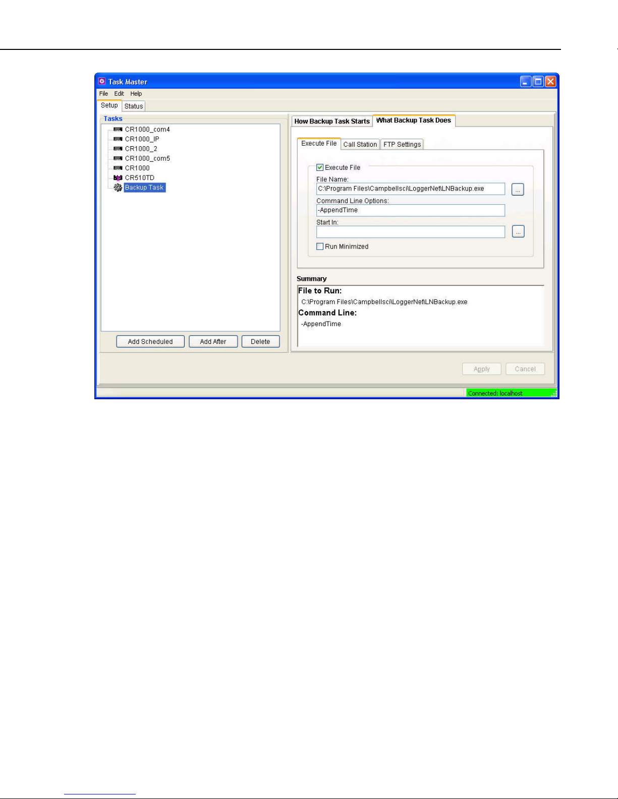
Section 2. Installation, Operation and Backup Procedures
Automatic Backup Configured in Task Master
2.3.2.4 Restoring the Network from a Backup File
To restore a network from a backup file, choose Network | Restore Network.
Select the *.bkp file that contains the network configuration you want to
restore. Note that this process DOES NOT append to the existing network —
the existing network will be overwritten when the restore is performed.
2.3.3 Loss of Computer Power
The LoggerNet communications server writes to several files in the \SYS
directory during normal operations. The most critical files are the data cache
table files and the network configuration files. The data cache files contain all
of the data that has been collected from the dataloggers by the LoggerNet
server. These files are kept open (or active) as long as data is being stored to
the file.
The configuration files contain information about each device in the datalogger
network, including collection schedules, device settings, and other parameters.
These files are written to frequently to make sure that they reflect the current
state and configuration of each device. The configuration files are only opened
as needed.
2-7
Page 40

Section 2. Installation, Operation and Backup Procedures
If computer system power is lost while the LoggerNet server is writing data to
the active files, the files can become corrupted, making the files inaccessible to
the server.
While loss of power won’t always cause a file problem, having files backed up
as described above will allow you to recover if a problem occurs. If a file does
get corrupted, all of the server’s working files need to be restored from backup
to maintain the synchronization in the server state.
2.3.4 Program Crashes
If the communication server crashes, there is a possibility that files can be
corrupted (note, however, that corruption is much less likely with a program
crash than during a power loss, since the computer operating system remains in
control and can close the files left open by the failed program). If, after a
program crash, the server does not run properly, you may need to restore the
data from backup.
If you have problems restarting the LoggerNet server after a program crash or
it crashes as soon as it starts, make sure that the LoggerNet server has not left a
process running. You can check this by going to the Windows Task Manager
and selecting the Process tab. In the list of processes look for the Toolbar or
one of the client applications. If one of these processes exists but the Toolbar
is not running, select this process and click “End Process”; you will be asked to
confirm the end process.
2.4 Installing/Running LoggerNet as a Service
If you have LoggerNet Admin, you can install and run LoggerNet as a service.
The advantage of running a software application as a service is that the
software will run even when no user is logged in to the computer system. Some
users may desire to run LoggerNet as a service, so that in the event of a loss of
computer system power LoggerNet will resume data collection and scheduled
task activities when power is restored to the computer and it “boots up”.
LoggerNet Admin includes LoggerNet Service Manager, which is used to
install and control LoggerNet when running as a service. The LoggerNet
Service Manager is opened from the Windows Start menu (Start | Programs |
Campbell Scientific | LoggerNet | LoggerNet Service Manager). The
LoggerNet Service Status box at the top of the LoggerNet Service Manager
window indicates whether or not LoggerNet is installed as a service and
whether or not the service is running. When you first open the LoggerNet
Service Manager, if LoggerNet has not been installed as a service you will
need to select the Install button. Note that LoggerNet must be closed to install
it as a service. If it is opened, you will be prompted to close it before you can
continue.
Once LoggerNet is installed as a service, you can use LoggerNet Service
Manager to Start the service (or Stop it if it is enabled). The LoggerNet service
can be uninstalled by selecting the Uninstall button.
One caveat to running LoggerNet as a service is if LoggerNet uses system
resources (such as a COM port that is continuously open waiting for datalogger
2-8
Page 41

Section 2. Installation, Operation and Backup Procedures
call-back attempts) these resources will be unavailable to other applications
until the service is stopped.
Note that when running LoggerNet as a service, tasks being run by the Task
Master cannot interact with the desktop. Therefore, any tasks set up in the
Task Master should not require any user interaction.
If LoggerNet is installed as a service, the service must be running for
LoggerNet to run (either automatically or manually). You will be prompted to
start the service if you try to launch LoggerNet manually when the service is
installed but not running.
The first time LoggerNet is installed as a service, a LoggerNet user account is
created. The LoggerNet service is run under this LoggerNet user account. This
allows the LoggerNet Service to always run in the same environment with
known user rights. You will be asked to enter and confirm a password for the
LoggerNet user account. The password you enter can later be used to log in to
the computer as the LoggerNet user. The password can be changed by pressing
the Options button and then pressing Change Password.
NOTE
NOTE
If the machine has a preexisting LoggerNet user account created
from LoggerNet 3.4, it will be necessary to stop, uninstall the
service, then reinstall the service in order to setup the password.
The LoggerNet user account will not show up in your list of
users when logging on to your computer. It can be viewed from
the Windows Control Panel. (In Windows 7, for example, from
the Control Panel, click User Accounts | Manage User Accounts |
Advanced tab | Advanced button, and then select Users from the
list of Local Users and Groups.) Although it is not available in
the drop-down list when logging on to your computer, you can
manually enter the user name (LoggerNet), enter the password,
and then select your local machine. (In Windows 7, the local
machine name is entered with the user name, i.e.,
machine_name\LoggerNet.)
2.4.1 Issues with Running LoggerNet as a Service
By default, the LoggerNet service is run under the LoggerNet user account.
This may cause some issues with write access and network drives. The issues,
along with their solutions, are described below:
2.4.1.1 Write Access
The LoggerNet user has write access only to the CampbellSci directories.
Therefore, if a task requires something to be written or done in a different
directory or on the desktop, the LoggerNet user does not have sufficient access
and the process will end in an error. This can be solved by giving the
LoggerNet user write access to the necessary directories.
2-9
Page 42

Section 2. Installation, Operation and Backup Procedures
Giving the LoggerNet user write access
This is the process for giving the LoggerNet user write access to a designated
directory in Windows XP. The process in other operating systems is similar.
• Right-click on the directory in Windows Explorer and choose
Properties.
• Go to the Security tab of the Properties dialog box and select Add. This
will open the Select Users, Computers, or Groups dialog box.
• From the Select Users, Computers, or Groups dialog box press the
Locations button. This will open the Locations dialog box.
• In the Locations dialog box, select the computer name and press OK.
• From the Select Users, Computers, or Groups dialog box press the
Advanced button. Then press the Find Now button. Select LoggerNet in
the list of names that appears at the bottom of the dialog box and press
OK. Note that <COMPUTER-NAME>/LoggerNet has been added to the
Object Names on the Select Users, Computers, or Groups dialog box.
Press the OK button to close the Select Users, Computers, or Groups
dialog box.
• The LoggerNet user should now be highlighted on the Properties dialog
box. Select the Full Control Allow check box to give LoggerNet full
permissions for the directory. Press the Apply button to apply the changes.
Press OK to close the dialog box.
• The LoggerNet user should now have full access to the designated
directory.
2.4.1.2 Network Drives
Network drive mappings are associated with individual user accounts.
Therefore, they cannot be used when running LoggerNet as a service. To use
network drives when running LoggerNet as a service, you must use the full
UNC path (e.g., \\computer_name\directory\filename). Note that the ability to
write to the network drives will be governed by Windows security. It will be
necessary to configure the LoggerNet service to run under an account that has
network privileges. This requires changes to the properties of the LoggerNet
service in Windows. Contact your network administrator for assistance.
2.5 Special Note on Windows XP Service Pack 2
With Service Pack 2, Microsoft has automatically enabled a firewall
application on each individual PC. This was done to protect PCs from invasion
by outside, unauthorized programs that may try to connect via a socket using
TCP/IP.
Remember, however, that LoggerNet is a client-server application that uses
TCP/IP as the link between clients and the server. This means that windows
such as Setup, Connect, Status Monitor, RTMC, etc., get their access to devices
and data only through the LoggerNet server. While, in the basic LoggerNet
2-10
Page 43

Section 2. Installation, Operation and Backup Procedures
installation most of these clients typically access the server on the same PC
(which will already be “behind” the PC’s local firewall), the server is capable
of distributing the same information to similar clients connected via TCP/IP
from anywhere in the world, revealing the true power of the client-server
design. If, for example, you want others to use RTMC or Data Filer to get data
from your LoggerNet PC, you can enable this remote connection by selecting
the Allow Remote Connections check box on the dialog box opened from
LoggerNet’s Tools | Options menu item. This causes the server to open a
socket on a specific port (default is port 6789) to listen for requests for data
from its clients. This is usually quite safe since: 1) no other application should
be trying to use this port, and 2) the server will only respond to LoggerNetspecific messages on this port (it will not run viruses or other unauthorized bits
of code). If you allow remote connections, however, the firewall in Windows
XP SP2 will put up a window telling you that it has blocked “Toolbar” and
asking if you wish to unblock Toolbar from Campbell Scientific. At this point,
if you click “Unblock”, Windows XP will make an exception for LoggerNet
and you should not have to unblock it each time you start it. You can reverse
this decision by opening the Windows Control Panel, selecting Windows
Firewall, and deleting Toolbar from the list of exceptions.
2-11
Page 44

Section 2. Installation, Operation and Backup Procedures
2-12
Page 45

Section 3. Introduction
3.1 What is LoggerNet?
LoggerNet is a software application that enables users to set up, configure, and
retrieve data from a network of Campbell Scientific dataloggers and share this
data over an Ethernet communications network. This software application is
designed to run under Windows XP, Windows Vista, and Windows 7.
LoggerNet software supports communication and data collection for Edlog
dataloggers including the CR500, CR510, CR10, CR10X, 21X, CR23X, and
CR7 in any of their mixed-array, table data, or PakBus operating systems, and
the CRBasic dataloggers including the CR200 Series, CR1000, CR3000,
CR800 Series, CR5000, CR9000, and CR9000X.
The LoggerNet software is written using advanced “client-server” architecture.
The server software engine runs in the background handling all of the
datalogger communications. The server also takes care of storing the data and
providing information to manage the datalogger network. In turn, the client
applications connect to the server to access the information collected from the
dataloggers.
One significant benefit of the software design is that some of the client
applications (RTMC, for instance) can be run on any computer that connects to
the main computer by a TCP/IP network connection. Some examples of these
networks are Local Area Network (LAN), Wide Area Network (WAN), or the
Internet. If you have LoggerNet Admin or LoggerNet Remote, any of the
client applications can log on to a remote LoggerNet server. Another benefit is
the efficiency that is gained, since several client applications can
simultaneously request and receive information from the software server.
LoggerNet is an ideal solution for users wanting a reliable data collection
system that is also flexible enough to meet a variety of needs.
3.1.1 What Next?
The ultimate goal with most datalogging applications is to retrieve data to a
computer for further analysis and manipulation. Now that you have installed
LoggerNet on your computer, how do you reach that goal?
The first step is to set up a communication link between your computer and the
datalogger station. This step may also include the configuration of peripheral
communication devices. Next you’ll need to develop a program for the
datalogger, and then send the program to the datalogger and ensure that
measurement results are viable. Once the datalogger has been storing data for
a period of time, you will want to collect that data and store it to a file on your
computer for further analysis.
LoggerNet provides the tools to accomplish these steps, as well as tools to
resolve problems along the way if they should arise. The remainder of this
section briefly reviews the steps and the various tools that can be used to
accomplish them. More detailed information is provided in the subsequent
sections of this manual.
3-1
Page 46

Section 3. Introduction
3.2 Overview of Major LoggerNet Functions and
Associated Software Applications
3.2.1 The Heart of it All – LoggerNet Toolbar
The LoggerNet Toolbar has several functions. The most important is starting
the server that handles all communications with the dataloggers in the network.
As long as the Toolbar is running, either visible or minimized, the server is
working and able to communicate with the dataloggers. Shutting down the
Toolbar also shuts down the server and suspends all communications with the
dataloggers in the network.
When you run LoggerNet from the Window’s Program menu or from a desktop
shortcut, you are launching the LoggerNet Toolbar. Some options on the
Toolbar launch applications that connect to the server and allow you to set up
the network or view the collected data. Other options launch stand-alone
applications to perform other functions, such as program editing. As you hover
over a category in the list on the left side of the toolbar, applications related to
that category will be shown on the right. Selecting an application in the righthand list will launch the application.
LoggerNet’s client-server design allows client applications to be run on the
same computer as LoggerNet, or on remote computers running LoggerNetData,
LoggerNet Admin, or LoggerNet Remote. Note that the LoggerNet Toolbar
must be up and running (or LoggerNet must be running as a service) and
Remote Connections must be enabled for remote computers to access a
LoggerNet server. For additional information on Remote Connections, refer to
Section 12.1, Allowing Remote Connections to the LoggerNet Server.
3.2.1.1 Toolbar Views
When first opened, LoggerNet displays a full view of the Toolbar.
If you prefer a smaller version of the toolbar, you can select Favorites View
from the View menu. This will switch to a small view of the toolbar containing
only icons for applications in the Favorites category. (For additional
information on the Favorites category, refer to the following section.)
3-2
Page 47

By default, the LoggerNet menus are not shown on the toolbar. Press the arrow
button in the upper right corner to view the LoggerNet menus as shown below.
The arrow button will change direction and can then be used to hide the menus.
3.2.1.2 Favorites Category
The Favorites category can be configured to display as many or as few
applications as desired by selecting the Tools | Options menu item and then
using the Favorites tab.
Section 3. Introduction
The Available Applications column shows all applications that are available in
LoggerNet. (Press the + sign next to a category to show the applications in that
category.) An application can be added to the Favorites category by selecting it
in the Available Applications column and pressing the right arrow key. An
application can be removed from the Favorites category by selecting it in the
Favorites column and pressing the left arrow key.
The applications will appear on the Toolbar’s Favorites category in the same
order as they appear in the Favorites column. The up and down arrow keys can
be used to rearrange the order of applications in the Favorites column. To move
3-3
Page 48

Section 3. Introduction
3.2.1.3 Toolbar Menus
an application up in the Favorites column, select the application and press the
up arrow until the application is in the desired location. Use the down arrow
key in a similar manner to move the application down in the Favorites column.
The following options are available from LoggerNet’s menu:
File Menu
Exit – Closes the LoggerNet application.
View Menu
Full View – This option is only available when in Favorites View and brings
up the full view of the Toolbar.
Favorites View – This option is only available when in Full View. It switches
from a full view of the Toolbar to a smaller view which shows icons for only
the Favorites category.
Hide Main Menu – Hides LoggerNet’s main menu. The main menu can be
displayed again by pressing the arrow key in the upper right-hand corner of the
Toolbar.
Tools Menu
Options – This option bring up the LoggerNet Options dialog box. From this
dialog box you can specify various options such as whether the toolbar always
stays on top, the behavior of the system tray icon, language, and whether
remote connections are allowed. You are also able to specify which
applications are included in the Favorites category.
Launch Menu
Provides a drop-down list of all the categories on the LoggerNet toolbar.
Hovering over a category will display a list of applications related to that
category. When an application is selected from this list, it will be started.
Help Menu
LoggerNet Help – Opens the LoggerNet on-line help file.
Check for Updates – Opens Campbell Scientific’s website to check for updates
to LoggerNet.
Give Feedback on LoggerNet – Opens a form on our website which allows you
to provide feedback on LoggerNet to Campbell Scientific.
About LoggerNet – Displays version and copyright information for LoggerNet.
3.2.1.4 Command Line Arguments
Command line arguments allow you to change LoggerNet’s default behavior
when it is started from a shortcut.
3-4
Page 49

Section 3. Introduction
Currently, there are three command line arguments:
/WorkDir Sets the working directory to something other than the default.
Usage:
“C:\Program Files\CampbellSci\LoggerNet\ToolBar.exe”
/WorkDir=C:\CampbellSci\test
where “C:\Program Files\CampbellSci\LoggerNet\ToolBar.exe”
is the directory and filename for the LoggerNet Toolbar (which
essentially is the LoggerNet server) and C:\CampbellSci\test is the
working directory to be used.
/M Launches LoggerNet in a minimized state. Usage:
“C:\Program Files\CampbellSci\LoggerNet\ToolBar.exe” /m
/IPPORT=XXXXX Causes the server to use port XXXXX for TCP/IP
communications with clients. Handy if some other software is
using the default port of 6789. Usage:
“C:\Program Files\CampbellSci\LoggerNet\ToolBar.exe” /ipport=12345
NOTE
If you are running LoggerNet Admin, which requires that you
log in to a particular sever with each client, you must specify this
alternate port number when entering the server address in the
login window (e.g., LocalHost:6700 or 192.168.7.123:6700).
NOTE
If LoggerNet is being run as a service (available in LoggerNet
Admin), you use LoggerNet Service Manager to specify an
alternate working directory or IP port.
3.2.1.5 Alternate Language Support
Certain LoggerNet clients can display the user interface component text (for
buttons, dialog boxes, etc.) in a language other than English if a separate
LoggerNet language package has been installed. If a language package is
installed on your machine, you will see the language in the list at Tools |
Options | Languages. When a new language is chosen, the Toolbar will
immediately reflect the change. Opened clients will not reflect the change until
they are closed and reopened.
Applications that support alternate languages are Setup, Connect, Status
Monitor, Task Master, Short Cut, CRBasic Editor, View Pro, CardConvert,
TroubleShooter, Network Planner, PakBus Graph, LogTool, the Device
Configuration Utility, Data Export, and the RWIS Administrator.
NOTE
Available alternate language packages are provided by Campbell
Scientific’s international representatives or on the CSI website.
They are not included in a standard LoggerNet installation.
3-5
Page 50

Section 3. Introduction
3.2.2 LoggerNet Admin/LoggerNet Remote
3.2.3 Setting Up Datalogger Communication Networks
LoggerNet Admin and LoggerNet Remote add functionality to aid in the
management of networks. One of these additions is the ability to access a
LoggerNet server from a remote computer. To do this, you need to “log in” to
the remote server. All of the standard LoggerNet clients that are capable of
accessing remote servers (such as Setup, Connect, or Status) include a Select
Server dialog box under the application’s File menu. This allows the user to
specify the TCP/IP address, as well as a user name and password if security is
enabled, for the remote server.
LoggerNet Admin and LoggerNet Remote also have the ability to launch more
than one of the same client screens. In LoggerNet, you can open only one client
window at a time. In LoggerNet Admin/LoggerNet Remote, if Launch Multiple
Clients is selected on the Toolbar’s Option menu, you can open two or more of
the same window. For instance, you can open one Connect Screen and connect
to datalogger A, and open a second Connect Screen and connect to datalogger
B.
Network setup tools allow you to define and configure the dataloggers in the
network, how they are connected to the computer, and what data should be
collected.
The most basic tool in setting up your network is the Setup Screen. The Setup
Screen can be used in either an EZ View or a Standard View. (For simplicity,
in this manual, references to the Setup Screen that do not specify EZ View or
Standard View, will refer to the Standard View of the Setup Screen.)
The EZ View of the Setup Screen uses the EZSetup Wizard which provides a
simple step-by-step sequence of screens, with on-screen help and many pre-set
values that make it easy to add a new datalogger and communications devices
to your LoggerNet network. You start with the type of datalogger you wish to
add, and then enter the settings for the communications devices used to reach
it, ending with a communications test and an opportunity to set the clock, send
a program, and set up an automatic data collection schedule.
The Standard View of the Setup Screen accomplishes the same tasks, but
allows you a bit more control when setting up your network, and allows for
more complex network configurations.
The Device Configuration Utility, or DevConfig, uses a direct serial port or IP
connection to set the settings in a device (such as the PakBus address or routing
information for a datalogger, or RF400 radio information) so that LoggerNet
can communicate with it. It can also be used to send a new operating system to
devices that accept a downloadable OS. DevConfig supports all CSI
dataloggers, as well as configurable communication devices such as RF400
radios, MD485s, and NL100s.
The Network Planner is a graphical application that assists the user in
designing a datalogger network. The user interacts with a drawing canvas on
which he places his stations and adds peripheral devices to those stations. He
then creates links between stations and specifies the nature of those links.
Finally, he specifies the activities that will take place between various devices
within the network. As the user does these things, the Network Planner
3-6
Page 51

automatically specifies many individual device settings such as PakBus
address, neighbor lists, verify intervals, network parameters, etc. The Network
Planner also provides an interface to allow the user to actually configure the
dataloggers and peripheral devices in his network as well as the LoggerNet
server.
LoggerNet also ships with a command line scripting tool, CoraScript, which
can be used to configure the datalogger network from a command prompt.
LoggerNet’s Scheduled Backup, Manual Backup, and Restore Network tools
are useful for backing up the entire datalogger network (refer to Section 2.3.2,
Back up the Network Map and Data Files).
3.2.4 Real Time Tools
LoggerNet’s real-time tools are used to connect to a datalogger, set the clock
and send a program to the datalogger, and view the data being collected from
the datalogger by the LoggerNet server. These tools include the Connect
Screen and RTMC.
The Connect Screen is used primarily for initializing or checking operation of a
datalogger and manually collecting data. This screen provides near real-time
communication with a datalogger. Utilities are available for sending programs
to or retrieving programs from a datalogger, checking or setting a datalogger
clock, and getting status information from the datalogger. There are windows
for displaying data either graphically or in numeric format, as well as setting
input locations, ports, and flags. You can also manually retrieve data in
various formats, and communicate with a datalogger in terminal emulation
mode.
Section 3. Introduction
RTMC is used to for real-time data displays of the data collected by the
LoggerNet server. You can create customized graphic displays that include
graphs, tables, dials, alarms, digital values and other graphic elements. These
displays automatically update when LoggerNet collects new data. Graphical
elements are also available for toggling ports or flags, or setting variables (or
input locations) in a datalogger. The displays created in RTMC can be
distributed to other users who have licenses to run RTMC Run-time software
(purchased separately). This allows a remote computer, accessible via TCP/IP,
to connect to the LoggerNet server and display the real-time data.
3.2.5 Network Status and Problem Solving
Since communications invariably fail at some point, LoggerNet includes
several tools to pinpoint where the problem lies.
The Status Monitor is used to monitor the health of datalogger network
communications. The integrity of the communications link can be verified
quickly from the color of the status icon for each device. A Communications
History graphic shows the success of communications over the last 24 hours.
Columns can be set up to display detailed statistics on communications quality
and data collection. For troubleshooting purposes, The LogTool application is
available to view operational log messages for the server as well as the lowlevel communication between the datalogger and the server. A Comm Test
window can also be launched from the Status Monitor.
3-7
Page 52

Section 3. Introduction
Troubleshooter is used to identify possible problems disrupting
communications or data collection. You can narrow the display to show only
the dataloggers in the network, or expand it to view the entire network.
Problems are highlighted in different colors to indicate levels of severity. You
can click on a potential problem to bring up a menu that allows you to go to the
Setup Screen or Status Monitor to fix the problem, bring up help on the
problem, or in some cases fix the problem directly. Finding a problem, you
can launch a separate Communications Test utility or open the server logs.
PakBus Graph provides a graphical display of a PakBus network, and quick
access to the PakBus settings in LoggerNet and other PakBus devices. PakBus
is a packet-switched protocol developed by Campbell Scientific that facilitates
communications between PakBus-capable devices, including dataloggers, some
communications peripherals (NL100s, RF400s, etc.), and LoggerNet itself.
Among the advantages of PakBus are: more robust communications due to
packet-based communications, multi-threading of communications (e.g., you
can use a keyboard/display at the same time as a PC is collecting data via
telecommunications; or two PCs can request data from a datalogger at the same
time), peer-to-peer communications (PakBus dataloggers can send to or request
data from other PakBus dataloggers without a PC involved), and dynamic
routing (PakBus devices can be configured as “routers” and learn about the
presence of other PakBus devices or alternative routes to those devices as they
come on line or routes change).
In addition to these tools, a Troubleshooting guide is provided in this manual.
Refer to Section 14, Troubleshooting Guide.
3.2.6 Network Management Tools
LoggerNet Admin includes some tools which are useful when managing large
networks, or when you need to manage networks with several users.
The LoggerNet Service Manager is a utility that allows you to install and run
LoggerNet as a service. Refer to Section 2.4, Installing/Running LoggerNet as
a Service, for additional information.
The Security Manager allows a LoggerNet network administrator to set up
accounts for each user on a system, and then allow each user access rights to
LoggerNet under one of five levels of security. The Security Manager is
available only with LoggerNet Admin or LoggerNet Remote. Refer to Section
11, Utilities Installed with LoggerNet Admin and LoggerNet Remote, for
details.
The Hole Monitor utility is used to monitor the hole collection activity in
LoggerNet. Holes are instances in the data cache where records are missing.
Holes are most often seen in large RF networks where data is being collected
via a data advise operation.
3.2.7 Creating and Editing Datalogger Programs
LoggerNet offers two programs editors (one for CRBasic datalogger programs
and one for Edlog datalogger programs), and a program generator (which
supports both programming language types).
3-8
Page 53

Section 3. Introduction
For straightforward “measurement/control/data storage” datalogger programs,
the Short Cut program generator is an excellent choice for datalogger program
creation. Short Cut prompts you for the type of datalogger, scan interval,
sensors to be measured (including those on multiplexers and other peripherals),
and desired final storage output. It then creates the program for you, along
with a wiring diagram showing how each of the sensors should be connected to
the datalogger. Short Cut’s resulting programs can even be imported into
Edlog or CRBasic Editor when you want to get a head start on more elaborate
programs. Short Cut is also available from the Campbell Scientific website
(www.campbellsci.com) so you can update it with newer sensor files as they
become available.
NOTE
While Short Cut programs can be imported into Edlog or the
CRBasic Editor, once they have been edited in one of these
programs, the modified program cannot be imported back into
Short Cut.
The CRBasic Editor is a program editor for the CR200 Series, CR1000,
CR3000, CR800 Series, CR5000, and CR9000 dataloggers. Instructions are
included for sensor measurement, program and peripheral control, data storage,
and peer-to-peer data transfer. The editor checks for program validity and
offers many user-configurable options to make editing long programs easier.
Edlog is the tool to create and edit datalogger programs for all Campbell
Scientific dataloggers except the CR200 Series, CR1000, CR3000, CR5000,
CR800 Series, and CR9000. Instructions are available for sensor
measurement, intermediate processing, program and peripheral control, and
data storage. The built-in precompiler provides error checking and warns of
potential problems in the program. For Edlog dataloggers with PakBus
operating systems, you can include settings for PakBus routing in the
datalogger program itself.
For those users of CR10X or CR510 dataloggers and Edlog programming who
are switching to CR1000 dataloggers (or CR23X users switching to CR3000
dataloggers), a Transformer utility has been developed. The Transformer reads
in an Edlog CSI or DLD file and generates a CRBasic program file. The two
files are displayed side-by-side for comparison purposes; double-click an
instruction in the Edlog program, and the associated instruction is highlighted
in the CRBasic program. Edlog program instructions that cannot be converted
directly to a CRBasic program instruction are listed in a Messages window and
are included as commented text in the CR* file. After conversion, the newly
created CR* file can be opened in the CRBasic Editor for further editing.
3.2.8 Working with Data Files
LoggerNet includes applications that allow you to view and process the data
collected from the dataloggers. These include the file viewer, View Pro, a
report generation tool, Split, and CardConvert (a binary data file file
converter).
View Pro is used to inspect data files, from either mixed-array or table data
dataloggers. You can also view data from an LNDB database. The data is
displayed in a tabular format by record or array. Data values can then be
chosen to display graphically on a line graph, histogram, XY plot, rainflow
3-9
Page 54

Section 3. Introduction
histogram, or FFT as appropriate for the data type. You can also print graphs
or save them to disk in a variety of formats.
Split is used to post process and generate reports from collected data files from
either mixed-array or table-based dataloggers. Traditionally it has been used to
separate mixed-array data files into individual files based on the array ID, but it
can also create files in custom formats for use in reports or as input to other
data applications, including converting mixed-array datalogger time stamps
(year, Julian day, Hour/Minute) to more conventional date/time stamp formats.
Split includes time series function, which can be used to provide summary
information from more frequent data (e.g., hourly summaries from one-minute
data).
The CardConvert file converter is used to convert TOB1, TOB2, and TOB3
files to TOA5, Array Compatible CSV, or CSIXML format (TOB2/TOB3 files
can also be converted to TOB1 format). TOB files are binary files that are
either created by LoggerNet during collection or are collected directly from a
compact flash or PCMCIA card installed in a CRX000 datalogger. A
command line file converter, toA_to_tob1, is also included in LoggerNet.
(Refer to Appendix B, Campbell Scientific File Formats, for additional
information on File Formats.)
3.2.9 Automating Tasks with Task Master
The Task Master is used to set up a Task that can be triggered on a defined
schedule or upon a data collection event from a datalogger. A Task can be data
collection from another datalogger, the transfer of a just collected data file to a
designated FTP directory, or anything that can be executed in a computing
environment (i.e., a command line operation, a program executable, a batch
file, or a script).
3.2.10 Managing External Data Storage Devices
CardConvert is used to retrieve binary data from a compact flash or PCMCIA
card, convert it to an ASCII or binary file, and save it to disk. CardConvert
supports binary data generated by CRX000 dataloggers.
The File Control functionality, accessed from the Connect Screen, can be used
to manage files created by CRX000 dataloggers on other, non proprietary
formatted, PC cards.
3.2.11 Optional Client Products Compatible with LoggerNet
3.2.11.1 LoggerNetData
LoggerNetData consists of client applications that can be installed and run
from a remote computer connected by TCP/IP to the computer running
LoggerNet. This connection could be a local area network (LAN) or the
Internet. LoggerNetData provides you with tools to remotely monitor collected
data, retrieve data, and view or process it on the remote PC.
The applications included with LoggerNetData are RTMC, View, Split, and
Data Filer. RTMC, View, and Split are described above. Data Filer is an
application used to manually collect data from LoggerNet’s data cache, and
3-10
Page 55

store the collected data to a file on a remote computer. Data Filer does not
collect data from a datalogger directly, but from the data cache. Therefore,
data collection must occur in LoggerNet (either by a scheduled or manual data
collection), for the data to be available to the Data Filer.
3.2.11.2 Data Display Clients
RTMC Run-Time is available separately from LoggerNet. It allows you to run
forms created in RTMC so that data can be displayed on a remote computer.
The CSI Web Server is used to display RTMC projects using a web browser.
Once the web server is in place, the only thing required to view the data is a
browser such as Internet Explorer or Firefox.
3.2.11.3 Baler
The Baler is another remote data retrieval client that creates “bales” of files
based on the date and time stamp of the collected data, and stores those files on
the remote PC. The individual baled files are saved to disk using part of this
date and time stamp for the name.
Section 3. Introduction
3.2.11.4 CSIOPC Server (PC-OPC)
CSIOPC is a client that can be run on a remote PC or the same PC as
LoggerNet. It makes data available from the LoggerNet server in an OPC
format. This allows use of the data by third party software applications that
communicate using the OPC protocol.
3.2.11.5 Software Development Kit
LoggerNet SDK, the LoggerNet Software Development kit, allows developers
to create custom applications to communicate with the LoggerNet server. The
kit includes ActiveX controls, along with a beginner’s guide, programmer’s
reference, and examples. Note that the SDK includes the development tools
only; LoggerNet must be purchased separately.
NOTE
Access to the LoggerNet server by remote clients requires that
Remote Connections be enabled in LoggerNet. See Section 12.1,
Allowing Remote Connections to the LoggerNet Server.
3.3 Getting Help for LoggerNet Applications
Detailed information on each application is included in subsequent sections of
this manual. Each application also has an on-line help system. On-line help
can be accessed by pressing the F1 key or by selecting Help from the
application’s menu. Additionally, Edlog and CRBasic program editors have
context sensitive help that can be displayed by right-clicking an instruction or
parameter.
Popup hints are available for many of the on-screen controls. Let the mouse
pointer hover over the control, text box or other screen feature; the hint will
appear automatically and remain visible for a few seconds. These hints will
3-11
Page 56

Section 3. Introduction
often explain the purpose of a control or a suggested action. For text boxes
where some of the text is hidden, the full text will appear in the hint.
3-12
Page 57

Section 4. Setting up Datalogger
Networks
The EZ and Standard Views of the Setup Screen provide ways to create and maintain the
communications link and data collection schedules for a network of dataloggers. The EZ
View uses the EZSetup Wizard which walks you through the setup step-by-step. In the
Standard View, you add devices and configure their settings on your own. Either method
will result in a network map with all of the devices and communications links to reach the
datalogger stations.
The Network Planner is a graphical application that assists the user in designing a PakBus
datalogger network.
The Device Configuration Utility, or DevConfig, is a stand-alone tool that can be used to
configure settings in the dataloggers themselves, as well as in communication devices such
as RF400 radios or NL100s.
4.1 Setup Screen – EZ View (EZSetup Wizard)
The EZ View of the Setup Screen uses the EZSetup Wizard. The wizard was
designed to walk you through the setup and configuration of your datalogger
network. As you work through the steps for the Wizard, each screen has fields
that are completed with the pertinent information about your station. In
addition to setting up a new station, the EZSetup Wizard can be used to edit an
existing station.
Open the wizard by pressing the Add button. The EZSetup Wizard starts with
the page shown below.
4-1
Page 58

Section 4. Setting up Datalogger Networks
Subsequent pages are similar. Previous and Next buttons are provided to move
through each step of the wizard. Progress is shown by the blue arrow next to
each step displayed at the left. Field descriptions and helpful tips are displayed
on the wizard page. If additional help is needed, the on-line help can be
opened by pressing F1 or the Help button on the bottom right of each page.
In the Communication Setup step you first select the datalogger type and give
it a name. (This name will also become the default file name for data files
collected from that datalogger.) Next you choose the connection type from the
possible communications methods supported for that datalogger. EZSetup
Wizard fills in as many communications settings as possible; in many cases
you can use the default settings. It also provides fields for user-entered
communications settings such as phone numbers and RF radio addresses.
The Datalogger Settings step is provided for fine tuning the connection to the
datalogger. The baud rate offered is typically the maximum baud rate
supported by that datalogger and communications medium; lower rates may be
required for cell phones or noisy telephone links. Enter a Security Code only if
the datalogger is configured – via the keyboard/display or settings in the
datalogger program – to use it. Note that the default Max Time On-Line
setting for most communications links is zero (“0 d 00 h 00 m”), which means
that LoggerNet will never hang up until you click Disconnect. For telephone
links, the default Max Time On-Line setting is 10 minutes in order to reduce
the possibility of inadvertent and expensive long distance or cellular telephone
charges. There are, however, other links that can result in expensive
connection charges, such as digital cellular links using TCP/IP that charge by
the byte. Leaving the datalogger connected also uses battery power, so if the
datalogger power supply is not recharged from a reliable source, it may
discharge its battery below safe levels. Be sure, therefore, that you do not
leave the datalogger connected beyond the time necessary to do the tasks you
need to do.
The Setup Summary step provides a list of the settings entered. You can use
the Previous button to return to a page and change these settings if necessary.
The Communications Test step allows you to test the communications link
before going any further. If the datalogger is not installed, you can skip this
and the next two steps.
If communication succeeds, you can move to the Datalogger Clock step where
you can check or set the datalogger’s clock to match the PC’s system time. If
the datalogger is in a different time zone, you can enter an offset in hours and
minutes.
The Send Program step allows you to send a program to the datalogger. This
may be a program you created with Short Cut, Edlog or the CRBasic Editor or
a program supplied by someone else. If it is a mixed-array datalogger, and the
datalogger is already running a program, you should associate the .DLD file so
that LoggerNet will use the labels for input locations and final storage.
Dataloggers with table-based operating systems (TD, PakBus, and CRx000)
will know their program if one is running and will provide table definitions that
contain the labels. If you don’t have a program for the datalogger you can skip
this step and send a program later from the Setup Screen or Connect Screen.
The Data Files step is where you define what data tables, or final storage areas,
should be collected by LoggerNet and saved to disk. If you used the EZSetup
4-2
Page 59
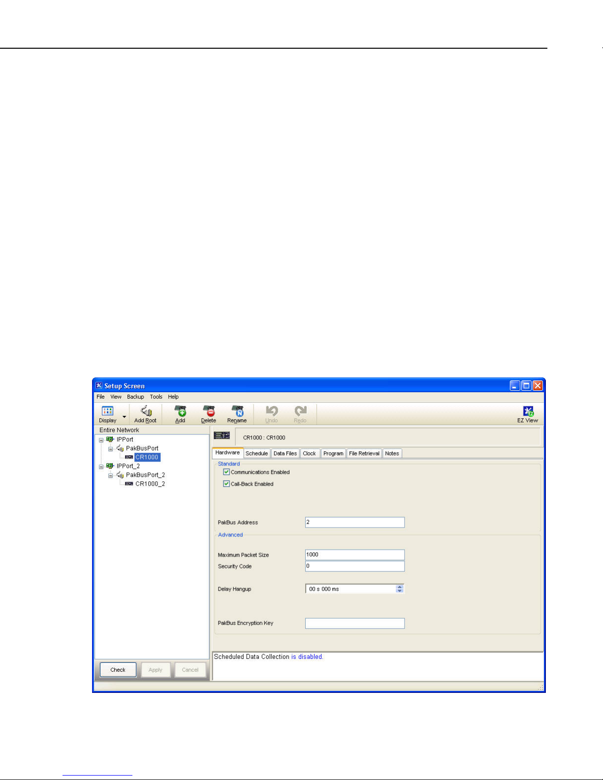
Section 4. Setting up Datalogger Networks
Wizard to send a program to a table-based datalogger, the software will already
be aware of the data tables that exist in the datalogger. If the program was
already loaded, or for some reason no tables are displayed, press the Get Tables
Definition button to retrieve the table names.
The Data Files step also has a Table Collected During Data Collection (or
Enabled for Scheduled Collection) field. When enabled, LoggerNet will
collect that table or final storage area from the datalogger on a manual or
scheduled data collection attempt.
The Scheduled Collection step is where you can define a schedule on which
LoggerNet will automatically call the datalogger and collect data.
Once a datalogger station has been configured, it can be edited by pressing the
Edit button to open the EZSetup Wizard. When editing in the EZSetup
Wizard, click a step in the Progress column to go directly to that step, or walk
through each wizard page using the Next button.
A datalogger can be deleted or renamed by highlighting the station and
pressing the Rename or Delete button.
4.2 Setup Screen — Standard View
The Standard View of the Setup Screen is divided into two parts: the Network
Map (left side of the screen) and the set up tabs (right side of the screen).
4-3
Page 60

Section 4. Setting up Datalogger Networks
The number of tabs will vary, based upon the type of device that is selected.
Some devices may have only hardware and notes tabs, while other devices,
such as dataloggers, have several tabs.
4.2.1 Adding Devices to the Network
Devices are added to the device map in the order that they appear in your
communications link. Let’s assume that your server computer is connected to
the datalogger via a telephone modem. You would first add a ComPort, then
the telephone modem, the remote phone modem, and the datalogger.
To add a ComPort to the network map either right click in the blank area of the
network map or click the Add Root button. Once the ComPort is in place you
can click the Add button to bring up the Add window. If you used the Add
Root button to add the ComPort, the Add window will automatically be
displayed.
Select Communications to see all communication devices that can be added to
a ComPort.
4-4
Page 61

Section 4. Setting up Datalogger Networks
The contents of the Add Device window will change as each device is added to
the network map. Only those devices that are valid components to add to the
last device added will be shown. Continue to add devices in this manner until
your network map is complete.
An alternative to the Add Device window is to press the right mouse button
while your cursor is on a device within the main device map window. A
shortcut menu like the one shown below will appear that will provide a list of
valid devices for connection to the device you have right clicked. For instance,
if you right click within the white space of the device map, the list will present
options for root devices such as ComPorts or IPPorts. When you right click a
ComPort, only valid connections for ComPorts will be presented.
4-5
Page 62
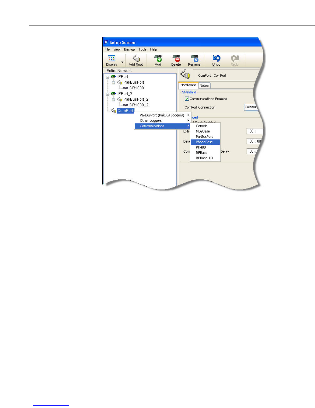
Section 4. Setting up Datalogger Networks
To delete a device from the network map select the device and click the Delete
button. This will delete the device and any devices that were connected below
it. A keyboard shortcut Ctrl+D will also delete the selected device.
4.2.2 Applying Changes, Undo and Redo
The device map is not saved or entered in LoggerNet until you click the Apply
button at the bottom of the screen. You can build a complete network and set
up the configurations for all of the devices without applying. However, it is a
good idea to build the network map in stages and periodically apply changes.
If there is a problem with the computer, any changes that have been applied
have been saved and will not have to be entered again.
Changing the network map or any of the device settings enables the Undo
button. Clicking the Undo button will roll back each change in reverse order to
the originally saved network and settings. If you undo a change and really
wanted to keep it, you can click the Redo button and restore the change.
Once the changes to the network map and device settings have been applied,
they can no longer be rolled back or restored using the Undo or Redo button.
Clicking the Cancel button before changes are applied will undo all of the
changes to the network map and settings, and restore the saved configuration.
4-6
Page 63

4.2.3 Renaming Network Devices
The names of all of the devices can be changed as desired. Rename a device
by selecting the device and either clicking again with the left mouse button on
the selected device or clicking the Rename button. The name of the selected
device will change to a text edit box and the new device name can be entered.
Valid names consist of letters, numbers and the underscore (_). The device
name must be unique in the network and the first character must be a letter.
Device names can reflect a location, layout, or physical location of network
devices. Think carefully when naming the devices since these names are used
throughout LoggerNet to refer to the devices.
4.2.4 Device Settings
When you highlight any device on the network shown on the left side of the
Setup Screen, configuration tabs appear on the right side with the relevant
settings. These settings are different for different devices and are described in
detail below. Some of the tabs have a Standard section and an Advanced
section. The Standard section contains information that must be reviewed to
ensure it matches the settings for the device. The Advanced section contains
settings that can be left at the default for most applications.
Section 4. Setting up Datalogger Networks
4.2.4.1 ComPort
All devices have a Notes tab which is only for the user’s convenience. It may
be used to keep notes about the device for future reference.
As with changes to the network map, the changes made to the device settings
are not used until they have been applied.
The ComPort (or serial port) has only Hardware and Notes tabs. Following is
an explanation of each of the fields on the Hardware tab.
Standard
Communications Enabled – Before communications can take place, all
devices in the communications chain must be enabled. The default setting for
this check box is Enabled.
ComPort Connection – This field designates the communications port
through which you will be connecting to the datalogger. Select the arrow to
the right of the field with a mouse to display a list containing the ComPorts that
are set up on your computer.
Advanced
Call-Back Enabled – Enabling call-back tells LoggerNet to watch for a callback from the datalogger on this port. If there is a phone modem attached it
will be set to accept incoming calls.
Dataloggers depicted in the Setup Screen must be configured for call-back as
well. For mixed array dataloggers, set the Call-Back ID to some value other
than 0 to accomplish this. For CRBasic dataloggers, enable the Call-Back
4-7
Page 64

Section 4. Setting up Datalogger Networks
Enabled check box for those dataloggers which should be enabled for callback.
Extra Response Time – LoggerNet is preconfigured to allow time for
responses based on type of device and baud rates. In this field, specify only the
additional time that LoggerNet should delay before terminating the
communications link if there is no response from the serial port. Additional
time may be needed in instances where the communications link is noisy or
network traffic is heavy. If extra response time is needed, it is typically set to 1
or 2 seconds.
Delay Hangup – The amount of time, in seconds and milliseconds, that
LoggerNet should delay before hanging up the link to the device. If a new
command to the device is issued before the delay has expired, communication
will not be terminated.
COM Port Communication Delay – The amount of time, in milliseconds,
that LoggerNet will wait after opening a communication port and before
sending data to the device. This can be useful when addressing drivers that
require a short delay before accepting data (such as an IRDA port driver).
NOTE
LoggerNet waits a certain amount of time for a response from
each device in a communications path. The extra response times
defined for the communications link are cumulative. Therefore,
the amount of time spent waiting for a device to respond is the
sum of all Extra Response Times defined, plus the default
response time for each device in the link. Add only the
minimum time necessary since very long response times can
delay other scheduled events while waiting for a device that is
not responding.
4.2.4.2 IPPort (Internet Protocol Serial Port)
Like the standard serial port, configuration for the IPPort has only Hardware
and Notes tabs. Following is an explanation of each of the fields on the
Hardware tab.
Standard
Communications Enabled – Before communication can take place, all
devices in the chain must be enabled. When this box is selected, the Internet
protocol serial port is enabled for communication.
Internet IP Address – In this field, enter the TCP/IP address and port through
which LoggerNet will communicate with the datalogger network. The address
is entered in the form ###.###.###.### for an IPv4 address or
[XXXX:XXXX:XXXX:XXXX:XXXX:XXXX:XXXX:XXXX] for an IPv6
address. (Alternately, a valid machine name can be entered.) The port is in the
form of :####. A typical IPv4 entry might be 123.123.123.123:1024. A
typical IPv6 entry might be [2620:24:8080:8600:85a1:fcf2:2172:11bf]:1024.
4-8
Page 65

Section 4. Setting up Datalogger Networks
Advanced
Call-back Enabled – Enabling call-back tells LoggerNet to watch for a callback from the datalogger on this port.
Dataloggers depicted in the Setup Screen must be configured for call-back as
well. For mixed array dataloggers, set the Call-Back ID to some value other
than 0 to accomplish this. For CRBasic dataloggers, enable the Call-Back
Enabled check box for those dataloggers which should be enabled for callback.
TCP Listen Only – When selected, LoggerNet will never attempt to make an
outgoing TCP Link on this IPPort. It will only listen for an incoming TCP callback. This option is useful for a datalogger doing TCP call-back from behind a
firewall. In this case, it is not possible to create a TCP connection from
LoggerNet to the datalogger and any time spent attempting to do so will be
wasted and may result in missing incoming connection attempts.
Extra Response Time – In this field, specify the additional time that
LoggerNet should delay before terminating the communications link if there is
no response from the IPPort. Additional time may be needed in instances
where the communications link is noisy or network traffic is heavy.
NOTES
Delay Hangup – The amount of time, in seconds and milliseconds, that
LoggerNet should delay before hanging up the link to the device. If a new
command to the device is issued before the delay has expired, communication
will not be terminated.
IP Port Used for Call-back – If call-back is enabled for the IP port, enter the
port number that LoggerNet should open and monitor for incoming call-back
messages.
AirLink Modem Name – If an AirLink modem is being used, enter the Device
ID set in it. By default, this is the 11-digit Electronic Serial Number of the
device.
When entering the IP address, do not use leading zeros for the
address numbers. For example use 123.123.2.34 instead of
123.123.002.034.
LoggerNet waits a certain amount of time for a response from
each device in a communications path. The extra response times
defined for the communications link are cumulative. Therefore,
the amount of time spent waiting for a device to respond is the
sum of all Extra Response Times defined, plus the default
response time for each device in the link. Add the minimum
time necessary since very long response times can delay other
scheduled events while waiting for a device that is not
responding.
4.2.4.3 TAPIPort (Telephony API)
The TAPI port uses the phone modems that have been installed and configured
in Windows. This eliminates the need for LoggerNet to specify the modem
type or work with initialization strings. Like the standard serial port,
4-9
Page 66

Section 4. Setting up Datalogger Networks
configuration for the TAPI port has only Hardware and Notes tabs. Following
is an explanation of each of the fields on the Hardware tab.
Standard
Communications Enabled – Before communication can take place, all
devices in the chain must be enabled. When this box is selected, the Internet
protocol serial port is enabled for communication.
TAPI Line – Select the modem you want to use for communication. The
modems listed are defined by Windows as part of the computer’s Modem
Setup. All of the parameters for the modem, including the baud rate have to be
set using the Windows Modem Setup dialog. If you are using the same modem
for dialup access you may have to change the settings for the different
applications.
Advanced
Call-back Enabled – Enabling call-back tells LoggerNet to watch for a callback from the datalogger on this port. If there is a phone modem attached it
will be set to monitor for incoming calls.
NOTES
Dataloggers depicted in the Setup Screen must be configured for call-back as
well. For mixed array dataloggers, set the Call-Back ID to some value other
than 0 to accomplish this. For CRBasic dataloggers, enable the Call-Back
Enabled check box for those dataloggers which should be enabled for callback.
Extra Response Time – In this field, specify the additional time that
LoggerNet should delay before terminating the communications link if there is
no response from the IPPort. Additional time may be needed in instances
where the communications link is noisy or network traffic is heavy.
Delay Hangup – The amount of time, in seconds and milliseconds, that
LoggerNet should delay before hanging up the link to the device. If a new
command to the device is issued before the delay has expired, communication
will not be terminated.
To communicate with dataloggers using the TAPI modem you
have to set the baud rate to match the communication capability
of the devices in the link. If you are using COM200 modems,
the baud rate must be set to 9600 on the TAPI modem. For use
over cell phone modems 1200 or 4800 baud may be required.
LoggerNet waits a certain amount of time for a response from
each device in a communications path. The extra response times
defined for the communications link are cumulative. Therefore,
the amount of time spent waiting for a device to respond is the
sum of all Extra Response Times defined, plus the default
response time for each device in the link. Add the minimum
time necessary since very long response times can delay other
scheduled events while waiting for a device that is not
responding.
4-10
Page 67

4.2.4.4 Datalogger
Dataloggers have several different tabs. Similar to the serial port, a hardware
tab is completed to specify communications settings. There are also tabs to
define the data to be collected, how often data should be collected, whether to
automatically update the datalogger’s clock, and a tab to send a program. Note
that not all dataloggers will have all the settings described below.
4.2.4.4.1 Hardware Tab
Standard
Communications Enabled – Before communication can take place, all
devices in the chain must be enabled. When this box is selected, the datalogger
is enabled for communication.
Call-back Enabled – Enabling call-back tells LoggerNet to watch for a callback from this datalogger. The parent PakBus port will be set up to receive
incoming calls.
The communication port (i.e., the root device) must be configured for call-back
as well. Enable the root device’s Call-Back Enabled check box to accomplish
this.
Section 4. Setting up Datalogger Networks
Maximum Time On-Line – This field is used to define a time limit for
maintaining a connection to the device. (This may be useful in avoiding costly
communication costs, in the event that a connection to a station is inadvertently
maintained for a long period of time.) Maximum Time On-Line applies to both
scheduled connections and manual connections. However, for manual
connections from the Connect Screen, it is always best to manually disconnect
rather than relying on LoggerNet to disconnect for you.
When the device is contacted on a schedule, communication with the device
will be terminated once this time limit is exceeded. A value of 0 in this field
indicates that there is no time limit on maintaining a connection to the device.
When the device is connected in the Connect Screen and the time limit
approaches, a dialog box is displayed warning the user that Max Time On-Line
is about to be exceeded. The dialog box has Reset Max Time and Don’t Reset
buttons. If the Reset Max Time button is pressed, the Max Time On-Line
counter will be reset. If the Don’t Reset button is pressed or if no button is
pressed, the connection will be terminated when Max Time On-Line is
reached.
The format for this field is 00 h(ours) 00 m(inutes) 00 s(econds).
4-11
Page 68

Section 4. Setting up Datalogger Networks
NOTE
If you are using LoggerNet Admin or LoggerNet Remote 4.0 and
using the Connect Screen to connect to a remote server that is
running an older version of LoggerNet, the behavior will be
different than described above. When connecting to a LoggerNet
3.4.1 server, you will be disconnected with no advanced warning
when Max Time On-Line is reached. A message will be
displayed indicating that Max Time On-Line has been reached.
When connecting to servers older than LoggerNet 3.4.1, the
behavior will be variable. Generally, you will be disconnected at
some point, but the timing of the disconnect will not be
predictable.
Maximum Baud Rate – Select the arrow to the right of this field to choose a
maximum baud rate for communication with this datalogger. Note that the
actual rate of communication may be limited by the capability of other devices
in the communications chain.
PakBus Address – Each device in a PakBus network has a unique address.
Valid addresses are 1 through 4094. 4094 is a broadcast address, and is
therefore reserved for the LoggerNet PC.
Advanced
Extra Response Time – In this field, specify the additional time that
LoggerNet should delay before terminating the communications link if there is
no response from the datalogger. Additional time may be needed in instances
where the communications link is noisy or network traffic is heavy.
Maximum Packet Size – Data is transferred in “chunks” called packets. For
most devices the default value is 2048 byes. The value entered in this field can
be changed in 32 byte increments. If a communications link is marginal,
reducing the packet size may improve reliability.
Security Code – A datalogger can have a security code to restrict access to the
datalogger. This helps prevent inadvertent changes to the datalogger’s program
or memory. A valid security code is any four digit, non-zero number. The
security code is set by the datalogger program, through a keyboard display, or
the remote keyboard utility. If a datalogger program that sets or changes
security is loaded into the datalogger, the Security Code in LoggerNet must be
changed to match so that the server can access the datalogger. (Security is not
available in the CR5000, CR9000, and CR200 Series dataloggers.)
Call-back ID – Call-back is a mode supported by some dataloggers where an
instruction in the datalogger program can initiate a call to the computer. The
call-back ID is sent by the datalogger to identify itself when contacting the host
computer. LoggerNet uses this value to know which datalogger initiated the
call-back.
Delay Hangup – The amount of time, in seconds and milliseconds, that
LoggerNet should delay before hanging up the link to the device. If a new
command to the device is issued before the delay has expired, communication
will not be terminated.
4-12
Page 69

Section 4. Setting up Datalogger Networks
BMP1 Station ID – The address that will be used for the device in the BMP1
network. When adding a new device to the network, this field will not show up
until after the Apply button has been pressed. The ID will be assigned
automatically by LoggerNet, but can be changed by the user. This allows the
user to designate unique addresses for all BMP1 devices across multiple
LoggerNet networks.
BMP1 Low Level Delay – the amount of time, in milliseconds, that LoggerNet
should delay after receiving a valid low level serial acknowledgement package
before sending out the next low level serial query packet. If the value is zero,
the query packet will be sent immediately.
This setting is useful in high-latency networks such as those involving the
RF95T. It can reduce the network bandwidth consumed by low level
exchanges which do not result in any new data.
PakBus Encryption Key ─ This setting specifies text that will be used to
generate the key for encrypting PakBus messages sent to or received from this
device. The key entered here must match the PakBus Encryption Key setting
in the device. (The device setting is entered using DevConfig, PakBus Graph,
Network Planner, or a CR1000KD.)
NOTES
4.2.4.4.2 Schedule Tab
The PakBus Encryption Key can be up to 63 bytes long and can include any
character with the exception of the Null character. Note that if Unicode
characters are included in the key, those characters may take up to three bytes
each.
If the PakBus Encryption Key device setting is specified as an empty string, the
device will not use PakBus encryption. If the PakBus Encryption Key device
setting is specified as a non-empty string, however, the device will not respond
to any PakBus message unless that message has been encrypted. AES-128
encryption is used.
LoggerNet waits a certain amount of time for a response from
each device in a communications path. The extra response times
defined for the communications link are cumulative. Therefore,
the amount of time spent waiting for a device to respond is the
sum of all Extra Response Times defined, plus the default
response time for each device in the link. Add the minimum
time necessary since very long response times can delay other
scheduled events while waiting for a device that is not
responding.
Refer to your datalogger operator’s manual for complete
information on its security functions.
The Schedule tab defines when LoggerNet will automatically check the
datalogger for new data.
Scheduled Collection Enabled – This check box activates the data collection
schedule defined on this tab. No data will be automatically collected if the
schedule is disabled.
4-13
Page 70

Section 4. Setting up Datalogger Networks
Apply to Other Stations – This button allows the schedule setup for this
datalogger to be copied to other stations in the network. Clicking the button
brings up a window that lists all of the dataloggers in the network. You can
select one or more dataloggers and then press OK to use the entered schedule.
To select more than one datalogger, hold down the Ctrl key while clicking the
dataloggers to select.
Base Date – The base date field is used to define the first date for scheduled
data retrieval. If the date entered in this field has already passed, a data
collection attempt will be made when the schedule is enabled and applied.
Base Time – This field is used to define the first time for scheduled data
retrieval. As with the Base Date field, if the time has already passed, a data
collection attempt will be made when the schedule is enabled and applied.
This setting is also used with the Collection Interval to determine the time data
collection will be performed.
CAUTION
Entering a zero for any of the intervals below will cause
LoggerNet to try and collect as fast as possible.
Collection Interval – This is the interval at which the datalogger will be
checked for new data. If this interval is set at 1 hour, new data will be
collected from the datalogger every hour.
Example: If the Base Date and Time are 1/1/99, 12:15 p.m., with an
interval of one hour, data collection attempts will be made at 15 minutes
past the hour, each hour.
Primary Retry Interval – If a data collection attempt is made but fails, you
can specify an interval on which another attempt will be made. This primary
retry interval starts at the time of failure, not on the original calling time and
interval. “Failures” may be caused by busy phone lines, noisy RF
environments, low batteries, damaged hardware, etc.
Number of Primary Retries – The number entered into this field is the
number of times the server will attempt to contact the datalogger on the
Primary Retry Interval. If all the collection attempts fail, then the server will
commence calling on the Secondary Retry Interval if it is enabled.
Secondary Retry Interval – If the secondary retry interval box is checked, the
specified interval is a calling interval that will be followed if all Primary
Retries fail. Data collection attempts will continue on the Secondary Interval
until a data collection attempt is successful, at which time, all retry statistics
are reset. The Secondary Retry Interval is based on the initial date and time
settings, not the time of the last failure. If the box is not checked the collection
schedule will return to the normal collection schedule and continue through the
primary retry schedule until communications are restored.
Typical use is to set the Primary Retries fairly close together, and the
Secondary Retry at a longer interval. For instance, if you are calling on an
hourly basis, the Primary Retries might be set to three tries, spaced five
minutes apart. The Secondary Interval then might be set at 2 hours.
4-14
Page 71

Section 4. Setting up Datalogger Networks
Stay On Collect Schedule – By default, when LoggerNet has missed a
scheduled collection because of some condition (i.e. LoggerNet was closed,
scheduled collection was disabled, the schedule was paused from the Status
Monitor, etc.), once the condition that prevented collection is no longer true, if
an entire collection interval has elapsed since the last collection attempt,
LoggerNet will immediately try to perform a collection. In some cases, this
may not be the desired behavior. Selecting the Stay On Collect Schedule check
box will cause LoggerNet to always wait until the next even Collection Interval
to perform a collection.
Reschedule On Data – When this box is selected, each time that data is
received for a station, the data collection schedule will be reset using the
current system time as the base time.
Poll for statistics ─ The Status Monitor displays information about datalogger
data collection and communication status. There are some potential useful
statistics (columns) that are available for some dataloggers that are not
available for other datalogger types. Sometimes there are statistics obtained
automatically as part of data collection for some dataloggers but can be only
obtained with additional communication commands for other dataloggers. In
this latter case, these statistics are not retrieved by default as users with slow or
expensive communication may not wish to incur the additional cost or time
associated with the extra commands. In cases where the user does want to
retrieve the additional statistics, the Poll for Statistics setting can be enabled to
request that the statistics are retrieved. The statistics will be retrieved during
scheduled or manual data collection.
The LoggerNet server maps Status Table values to server statistics as follows:
Server Statistic
(displayed in Status
Monitor)
CR1000
CR800
CR3000
CR200
Status Table Values
CR10XPB
CR23XPB
CR510PB
CR5000
CR9000X
WatchDog Err WatchDogErrors WatchDogCnt WatchDog WatchDogErrors
Prog Overrun SkippedScan SkipScan Overruns SkippedScan SkippedScan
Low Volt Stopped Low12VCount
Low 5V Low5VCount
Lith Batt Volt LithiumBattery LithBat LithiumBattery Battery
Collect Ports and Flags – If this box is checked, the current state of the ports
and flags is collected and stored in LoggerNet’s internal data cache. This
allows functions such as the Numeric Display and view ports and flags to get
updated data with scheduled data collection.
When the Server’s Table Definitions are Invalid – This option determines
what action should be taken in the data cache during scheduled data collection
(or upon the arrival of a One Way Data or Data Advise record) when
LoggerNet determines that the table definitions it has stored for a table-based
datalogger and the table definitions actually in the datalogger do not match.
4-15
Page 72

Section 4. Setting up Datalogger Networks
• Automatically Reset Changed Tables – LoggerNet will reset (delete and
recreate) any tables that have changed. Unchanged tables will not be reset.
Scheduled data collection will continue without action from the user.
• Stop Collection Until Manually Updated – Scheduled data collection will
be halted until the user manually updates the table definitions (Setup
Screen, Data Files tab, Get Table Definitions button). At that time, the
user will be prompted to Merge or Reset the table definitions.
Data Advise/One Way Data Hole Collection – A discontinuity in collected
data is referred to as a hole. Data Advise or One Way Data hole collection does
not apply to holes collected during manual data collection or scheduled data
collection since the default behavior of those collection methods will always
retrieve the records needed from the datalogger and store them in the data
cache in sequential order. However, there are settings in LoggerNet and other
data collection methods that can produce missing records in the data cache.
One Way Data and Data Advise are two collection methods that can produce
holes. These collection methods both rely on the datalogger to send records to
LoggerNet. Since the transmission of these records is unacknowledged, there is
a possibility that the data will be lost. If LoggerNet doesn’t receive a record for
any reason, a hole is created. If the Data Advise or One Way Data hole
collection check box is selected, LoggerNet will attempt to contact the
datalogger and request the missing records. Otherwise, LoggerNet will not
attempt to collect records missing from the data cache.
NOTE
Please note that LoggerNet puts records from Data Advise or One Way Data
hole collection in the .dat files as they are received. If there are holes in the
data that are retrieved later, the records will not be in sequential order in the
.dat file created by LoggerNet.
Data Advise or One Way Data hole collection will not occur at a
time when doing so would force the communication link to be
dialed.
Additional Field Available in LoggerNet Admin/LoggerNet Remote
Collect Via Data Advise – When this option is enabled, an agreement is
established between the LoggerNet server and the datalogger. As part of the
Data Advise agreement, LoggerNet reports the tables that are marked for
collection and the datalogger stores that information in memory. When the
datalogger receives a communication packet of any kind, it checks for new
records in the tables marked for collection. If a new record exists, it is sent by
the datalogger to the LoggerNet server.
Data Advise is used within RF telemetry networks to increase the speed of data
collection. The RF polling process using the TD-RF (“Time-division polling”)
PROM or OS can take advantage of the Data Advise agreement to collect data
very quickly by broadcasting a communication packet to all dataloggers in the
RFBase-TD network concurrently. This broadcast packet triggers all
dataloggers to check for and send any new records at once. The records are
simultaneously stored in the individual RF remote modems (RFRemote-TD)
until retrieved through the RF polling process (initiated by the RFBase-TD).
4-16
Page 73

Section 4. Setting up Datalogger Networks
4.2.4.4.3 Final Storage Area 1 and 2 Tab (Edlog Dataloggers with Mixed-array Operating
System)
Mixed-array dataloggers include the 21X, CR500, CR510, CR10, CR10X,
21X, CR23X, and CR7. When the datalogger program stores data in a mixedarray datalogger, the data arrays are stored in a final storage area. Some
dataloggers, such as the CR10X, have two final storage areas while others,
such as the 21X, have only one. This tab is used to define the output file name
and location, the data file format and other output options for the data stored in
the final storage area.
Enabled for Collection – The specified final storage area will be included in
the collected data if this box is checked.
Output File Name – This is the name and directory path for the output file
where the final storage data will be saved after being collected from the
datalogger during manual data collection from the Connect Screen or during
scheduled data collection.
Use Default File Name – Checking this box will set the collected data file
name to the default value, which consists of the name of the station and
number of the final storage area.
File Output Option – This option allows you to choose whether new data
collected from the station is appended to the data file, overwrites the old data in
the data file, or is not stored to a data file. The default option is to append to
the data file so the old data is not lost. If the data file is used only for a realtime display or such that only the last data collected is needed, overwrite can
be used to replace the old data with the new collected data. If the data is only
going to be used within LoggerNet for display on the Connect Screen graph or
numeric display, or for RTMC, you can choose no output file and a limited
amount of data will be kept in LoggerNet’s internal data cache.
Output Format – Select the format for the output file.
− ASCII, Comma separated writes data to the file in ASCII text format one
record per line with commas between the data values. This file can be
opened in LoggerNet View, a text editor, processed using Split, or brought
into a spreadsheet application.
− ASCII, Printable writes data to the file in ASCII text format separated
into columns separated by tabs. The column number precedes each data
value in the record. Only 80 characters will be placed on each line,
columns that don’t fit the 80 characters are placed on the next line. This
file format can be opened in LoggerNet View, a text editor, or processed
using Split. See the example data file below.
4-17
Page 74

Section 4. Setting up Datalogger Networks
01+0109. 02+2002. 03+0038. 04+1639. 05+15.00 06+13.20 07+24.79 08+073.9
09+269.0 10–1.000
01+0109. 02+2002. 03+0038. 04+1639. 05+25.00 06+13.20 07+24.79 08+073.9
09+279.0 10–.988
01+0109. 02+2002. 03+0038. 04+1639. 05+35.00 06+13.20 07+24.79 08+074.0
09+289.0 10–.946
01+0109. 02+2002. 03+0038. 04+1639. 05+45.00 06+13.20 07+24.79 08+074.0
09+299.0 10–.875
01+0109. 02+2002. 03+0038. 04+1639. 05+55.00 06+13.20 07+24.79 08+074.0
09+309.0 10–.777
01+0112. 02+2002. 03+0038. 04+1640. 05+0.000 06+13.20 07+24.79 08+074.0
09+074.1 10+1638. 11+18.00 12+13.19
01+0109. 02+2002. 03+0038. 04+1640. 05+5.000 06+13.20 07+24.78 08+074.0
09+319.0 10–.656
− Binary writes the data to a file in a binary format. The advantage of the
binary format is that it is more compact so the size of the file is much
smaller than for the ASCII based files. The disadvantage is that it’s
unreadable except using View or by post-processing with Split.
Collect Mode – The collect mode allows you to choose how much data to
collect when getting data from the datalogger.
• Data Logged Since Last Collection – When LoggerNet calls the
datalogger to collect data, it will try to get all of the data stored by the
datalogger since the previous call. If this is the first call to a datalogger
there might be a lot of historical data stored. When Collect All on First
Collection is checked, LoggerNet will collect all data in the datalogger the
first time data is collected. If Collect All on First Collection is not
checked, the first call to the datalogger will collect the number of arrays
specified in the Arrays to Collect on First Collection field. This allows
you to avoid keeping communications tied up while all the historical data
is collected.
• Most Recently Logged Arrays – This option is used when you are
interested in only the most recently stored data. When this option is
selected you can specify how many arrays back from the most recent array
should be included when data is collected from the datalogger.
4.2.4.4.4 Data Files Tab (CRBasic Dataloggers, and Edlog Dataloggers with Table Data
and PakBus Operating systems)
Table-based dataloggers include the CR10T, CR510TD, CR10X-TD,
CR23X-TD, CR1000, CR800 Series, CR3000, CR5000, CR9000, and CR200
Series. Data output to final storage is stored as records in tables. The Data
Files tab is used to define what data tables will be collected from the
datalogger, along with the output file name and format.
Tables to be Collected – All of the available tables in the datalogger are listed
in the column on the left. If no tables are listed, click the Get Table Definitions
button. The tables selected for collection are shown with a green check mark
and the excluded tables are shown with a red ‘X’. Data from the selected
tables will be collected from the datalogger during scheduled data collection.
4-18
Page 75

Section 4. Setting up Datalogger Networks
The individual tables can be highlighted by clicking the table name. The
settings on the right side of the window apply to the highlighted table. The
name of the highlighted table appears at the top of the settings. Double
clicking a table name will toggle collection of that table on or off.
Included for Scheduled Collection – If this box is checked the specified table
is included in data collection. This can be changed either by clicking the check
box or double clicking the name of the table in the list.
Output File Name – This setting defines the file name and path for the output
data file that contains the data collected from the datalogger. Clicking the
browse button ( … ) at the right of the box will allow you to choose another
directory or file name for the collected data. The data from each table is stored
in a separate output file.
Use Default File Name – Checking this box will set the collected data file
name to the default value, which consists of the name of the station and the
name of the table.
File Output Option – This option allows you to choose whether new data
collected from the station is appended to the data file, overwrites the old data in
the data file, creates a new data file with a unique name, or is not stored to a
data file. The default option is to append to the data file so the old data is not
lost.
If the data file is used only for a real-time display or such that only the last data
collected is needed, overwrite will replace the old data with the newly collected
data.
If the data is only going to be used within LoggerNet for display on the
Connect Screen graph or Numeric Display, or for RTMC, you can choose no
output file and the data will only be kept in LoggerNet’s internal data cache
(see Appendix D.2, LoggerNet Server Data Cache, for more about the data
cache).
Output Format – Select the format for the output file.
ASCII, table data, no header – The data is output with timestamp
and data values separated by commas with no header. When this
option is selected, the Browse button to the right of the Output
Format field becomes available. It launches a dialog box from
which to specify if a timestamp and record number should be
included, if strings should be surrounded by quotation marks,
and whether midnight is specified as 2400 or 0000.
ASCII table data, short header (TOACI1) – The data is output in
Table Oriented ASCII format type 1 which has a two line header
and data formatted the same as the ASCII table format.
ASCII table data, long header (TOA5) – The data is output in
Table Oriented ASCII format type 5 which has a multi-line
header and data values separated by commas. When this option
is selected, the Browse button to the right of the Output Format
field becomes available. It launches a dialog box from which to
4-19
Page 76

Section 4. Setting up Datalogger Networks
Binary table data (TOB1) – The data is stored in Table Oriented
Array Compatible CSV – This option allows for the
CSIXML – The data is stored in XML format with Campbell
specify if a timestamp and record number should be included,
and whether midnight is specified as 2400 or 0000.
Binary format type 1. When this option is selected, the Browse
button to the right of the Output Format field becomes available.
It launches a dialog box from which to specify if a timestamp
and record number should be included.
customization of the output file. It is used most often to produce
files compatible with our mixed array datalogger types. When
this option is selected the Browse button to the right of the
Output Format field becomes available. It launches a dialog box
from which to select the custom output options.
Scientific defined elements and attributes. Refer to Appendix B,
Campbell Scientific File Formats, for more information. When
this option is selected, the Browse button to the right of the
Output Format field becomes available. It launches a dialog box
from which to specify if a timestamp and record number should
be included, and whether midnight is specified as 2400 or 0000.
Collect Mode – The collect mode allows you to choose how much data to
collect when getting data from the datalogger.
• Data Logged Since Last Collection – When LoggerNet calls the
datalogger to collect data, it will try to get all of the data stored by the
datalogger since the previous call. If this is the first call to a datalogger
there might be a lot of historical data stored. When Collect All on First
Collection is checked, LoggerNet will collect all data in the datalogger the
first time data is collected. If Collect All on First Collection is not
checked, the first call to the datalogger will collect the number of records
specified in the Records to Collect on First Collection field. This allows
you to avoid keeping communications tied up while all the historical data
is collected.
• Most Recently Logged Records – This option is used when you are
interested in only the most recently stored data. During each data
collection, the number of records specified in the Records to Collect field
will be collected.
• Collect At Most – During each data collection, LoggerNet will collect up
to the number of records specified in the Records to Collect field. In
contrast to the Most Recently Logged Records mode, the Collect At Most
mode will not duplicate records previously collected. Therefore, fewer
records than the number specified may be collected.
Get Table Definitions – When this button is pressed, LoggerNet will query the
datalogger for its table definitions. This should only be needed the first time
connecting to a station or when the datalogger program has changed. New
table definitions will cause the previous output data file to be saved with a
different name and a new data file will be created to save the data.
4-20
Page 77

Section 4. Setting up Datalogger Networks
Use Reported Station Name – Enabling this check box will cause the station
name from the Status Table to be used in the header of the data files. If this
check box is not enabled, the network map station name will be used.
NOTE
4.2.4.4.5 Clock Tab
This check box affects only the header of the data files. It has no
effect on the filenames.
Time Zone Offset – A value can be entered into this field to set an offset for
the datalogger’s clock from the server’s clock, any time a clock set is
performed (manual or automatic). A positive value sets the datalogger’s clock
ahead of the PC’s clock; a negative value sets the datalogger’s clock behind the
PC’s clock. This may be useful if the server and the datalogger are in different
time zones.
Enabled – Select this box to automatically compare the datalogger’s clock to
the LoggerNet server PC’s clock based on the schedule defined by the other
parameters on this tab. If the datalogger’s time differs from the server’s time
by more than a specified amount, the datalogger’s clock will be set to the
server’s time.
A separate call to the datalogger will not be made exclusively to process a
clock check. A clock check will be made when the server contacts the
datalogger for some other function.
Setting up a clock check may not be desirable. It is possible to end up with
missing data or duplicate data if the datalogger’s clock is set forward or
backward enough to skip or duplicate a data storage event. Special
consideration should be given if the PC clock automatically adjusts for
Daylight Savings Time.
Refer to Section 4.2.6, Setting the Clock, for additional information on setting
and checking the clock.
Initial Date – The initial date field is used to define the date on which the first
clock check will occur. If the date entered in this field has already passed, the
datalogger’s clock will be checked at the next scheduled data collection.
Initial Time – This field is used to define the time at which the first clock
check will occur. As with the Initial Date field, if the time has already passed,
the clock will be checked at the next scheduled data collection.
Interval – The interval at which a clock check should be performed is
specified in the Interval field. If this interval is set at 1 day, the datalogger’s
clock will be checked daily, based on the initial date and time.
Allowed Clock Deviation – The Allowed Clock Deviation field is used to
specify the number of seconds the datalogger’s clock can differ from the
server’s before the server resets the datalogger’s clock.
Check Clocks – Press this button to manually initiate a clock check of the
LoggerNet server and datalogger clocks. The two values are displayed in the
Adjusted Server Date/Time and Station Date/Time fields, respectively.
4-21
Page 78

Section 4. Setting up Datalogger Networks
Set Station Clock – Press this button to manually set the clock to that of the
LoggerNet server.
NOTE
The Allowed Clock Deviation setting will prevent a manual
clock set from being carried out if the difference between the
datalogger’s and server’s clocks is less than the specified
deviation.
4.2.4.4.6 Program Tab
The program tab displays the name of the program currently running in the
datalogger, if it is known by the LoggerNet server. Table-based dataloggers
store program information in the table definitions. If the table definitions have
been retrieved from the datalogger, LoggerNet should know the name of the
running program. However, mixed-array dataloggers do not store the program
name internally. LoggerNet is made aware of the program name and output
table information when a new program is sent, or when a DLD file that
contains this information is associated with the datalogger. To send a new
program to the datalogger, press the Send button. To associate a program
name with the datalogger, press the Associate button. See Section 5.1.6,
Program Association, for more information.
4.2.4.4.7 File Retrieval Tab (CR1000, CR3000, CR800 Series, and Edlog Dataloggers with
PakBus Operating Systems)
Retrieval Mode – This option determines the schedule for file retrieval.
Disabled – No files are retrieved.
Follow Scheduled Data Collection – Files will be retrieved on the same
schedule that has been set up for scheduled data collection on the
Schedule tab.
New Schedule – Files will be retrieved based on the Base Date and Time
and Collection Interval defined below.
Base Date/Time – Enter a date and a time that the first file retrieval attempt for
the device should occur. If the date and time reflected by these fields has
already passed, retrieval will be attempted immediately when the schedule is
enabled.
Retrieval Interval – Enter the interval on which files should be retrieved from
the device. The retrieval interval is relative to the Base Date and Time entries.
For instance, if the Base Time is set at 12:15 and the interval is set for 1 hour,
file retrieval will be attempted at 12:15, 1:15, 2:15, etc. The format for this
field is 00 d(ays) 00 h(ours) 00 m(inutes) 00 s(econds) 00 m(illi)s(econds).
Delete Files After Retrieval – When this box is selected, the files will be
deleted from the datalogger after they are retrieved.
Add New – When this button is pressed, a new pattern is added to the list of
files to be retrieved. The user must then designate the File Pattern, Output
Directory, Max Files, Force Retrieval, and Record If Skipped fields for this
pattern.
4-22
Page 79

Section 4. Setting up Datalogger Networks
Delete – When this button is pressed, the selected pattern is deleted from the
list of files to be retrieved.
Edit File Pattern – Specifies a file pattern that will select the files that will be
retrieved. Select an option from the drop-down list or type it in directly. This
can be an exact filename or it can contain the wildcard characters “*” or “?”.
The asterisk is able to replace zero or more characters while the question mark
replaces exactly one character. The file pattern can also have a prefix indicating
the drive from which to retrieve the files. For example, USR:*.jpg will select
all .jpg files on the USR drive. Note that the file pattern is case insensitive.
Output Directory – Enter the directory to store the retrieved files. It can be
entered into the field directly, or you can press the browse button to the right of
the field to select a path from the Explorer window.
Max Files – Specifies the maximum number of files that can be retrieved on
each retrieval. The newest files will be retrieved.
Force Retrieval – When this box is selected, a file that matches the file pattern
will be retrieved regardless of the file’s timestamp or whether the file has
already been retrieved.
Record If Skipped – When this box is selected, the names and dates of any
files that are not retrieved because of the Max Files parameter will be recorded
and they will not be retrieved later. If this box is not selected, the skipped files
can be retrieved in a later attempt.
4.2.4.5 PhoneBase
The PhoneBase is a telephone modem connected to one of the server’s
ComPorts to provide access to other devices in the datalogger network. The
PhoneBase has only Hardware and Notes tabs. This device must be properly
installed and configured in the operating system to use one of the computer’s
ComPorts before it can be used by LoggerNet.
Standard
Communications Enabled – Before communications can take place, all
devices in the chain must have the Communications Enabled box checked.
When this box is selected, communications to the phone modem are enabled.
Maximum Baud Rate – Select the arrow to the right of this field to choose a
maximum baud rate for communication with this device. Note that the actual
rate of communication may be limited by the capability of other devices in the
communications chain.
Edit Modem Database – The modem connected to the server computer may
not be listed in the database, or the user may desire to change the modem
configurations. When the Edit Modem Database button is selected, the reset
and initialization strings for the selected modem are displayed. You can
change these settings or add a custom modem to the list. If you change the
settings for one of the standard modems you will have to save it to a new name
to use it. The only modems that can be deleted from the list are modems that
have been added by the user.
4-23
Page 80

Section 4. Setting up Datalogger Networks
Modem Type – Use the drop down list box to select the type of modem that is
attached to the server computer’s communications port. In most instances, the
<default modem> should work.
Advanced
Extra Response Time – In this field, specify the additional time that the
LoggerNet server should delay before terminating the communications link if
there is no response from the phone modem. Additional time may be needed in
instances where the communications link is noisy or network traffic is heavy.
Delay Hangup – The amount of time, in seconds and milliseconds, that
LoggerNet should delay before hanging up the link to the device. If a new
command to the device is issued before the delay has expired, communication
will not be terminated.
NOTE
LoggerNet waits a certain amount of time for a response from
each device in a communications path. The extra response times
defined for the communications link are cumulative. Therefore,
the amount of time spent waiting for a device to respond is the
sum of all Extra Response Times defined, plus the default
response time for each device in the link. Add the minimum
time necessary since very long response times can delay other
scheduled events while waiting for a device that is not
responding.
4.2.4.6 PhoneRemote
The Hardware tab of the remote phone modem is used to set up the dialing
string for the attached remote device. It has the following controls:
Communications Enabled – Before communication can take place, all
devices in the chain must have the Communications Enabled box checked.
When this box is selected, communication to the remote phone modem is
enabled.
Phone Number/Delay Field – This field is used to enter the telephone
numbers or dialing strings for the remote modem. To add a number to the list
simply click the <add phone number> field and type in the number. Spaces,
dashes and parentheses are usually ignored by the modem. To remove or
change a number, highlight the number and delete or click the number and use
backspace.
Multiple phone numbers are allowed to accommodate entry of access codes,
credit card numbers, or other numbers that may be needed for communication
to the remote modem and its attached device. As an entry is created a new line
is added for additional entries as needed. The first phone number will be
dialed following the specified delay. The next number will then be dialed after
the delay specified. The amount of time to delay is in milliseconds so a 5second delay would be entered as 5000 milliseconds.
4-24
Page 81

Section 4. Setting up Datalogger Networks
NOTES
4.2.4.7 RFBase
If the answering phone is a voice modem, a code must be entered
at the end of the dial string to put the modem into data mode.
Use *9 for a VS1 or 9 for a COM300/310/320. The code should
be sent after the modem has answered and the communication
link has been negotiated. Use the Delay field or insert one or
more commas (resulting in a 2 second delay for each comma) to
pause before sending the code. A typical dial string in this
instance might be 1-435-555-1212,,,,,9. The COM320 may
require an additional 9 to ensure that the 9 is received, e.g., 1435-555-1212,,,,,,9,9.
Precede the phone number with a P to change from Tone to Pulse
dialing.
The RF base modem acts as a gateway device that provides RF communication
with the remote RF modems connected to dataloggers at the field site.
Standard
Communications Enabled – Before communications can take place, all
devices in the chain must have the Communications Enabled box checked.
When this box is selected, communication to the RF base is enabled.
Maximum Time On-Line – This field is used to define a time limit for
maintaining a connection to the device. (This may be useful in avoiding costly
communication costs, in the event that a connection to a station is inadvertently
maintained for a long period of time.) Maximum Time On-Line applies to both
scheduled connections and manual connections. However, for manual
connections from the Connect Screen, it is always best to manually disconnect
rather than relying on LoggerNet to disconnect for you.
When the device is contacted on a schedule, communication with the device
will be terminated once this time limit is exceeded. A value of 0 in this field
indicates that there is no time limit on maintaining a connection to the device.
When the device is connected in the Connect Screen and the time limit
approaches, a dialog box is displayed warning the user that Max Time On-Line
is about to be exceeded. The dialog box has Reset Max Time and Don’t Reset
buttons. If the Reset Max Time button is pressed, the Max Time On-Line
counter will be reset. If the Don’t Reset button is pressed or if no button is
pressed, the connection will be terminated when Max Time On-Line is
reached.
The format for this field is 00 h(ours) 00 m(inutes) 00 s(econds).
4-25
Page 82

Section 4. Setting up Datalogger Networks
NOTE
If you are using LoggerNet Admin or LoggerNet Remote 4.0 and
using the Connect Screen to connect to a remote server that is
running an older version of LoggerNet, the behavior will be
different than described above. When connecting to a LoggerNet
3.4.1 server, you will be disconnected with no advanced warning
when Max Time On-Line is reached. A message will be
displayed indicating that Max Time On-Line has been reached.
When connecting to servers older than LoggerNet 3.4.1, the
behavior will be variable. Generally, you will be disconnected at
some point, but the timing of the disconnect will not be
predictable.
Maximum Baud Rate – Select the arrow to the right of this field to choose a
maximum baud rate for communication with this device. Note that the actual
rate of communication may be limited by the capability of other devices in the
communications chain.
Advanced
Extra Response Time – In this field, specify the additional time that
LoggerNet should delay before terminating the communications link if there is
no response from the RFBase. Additional time may be needed in instances
where the communications link is noisy or network traffic is heavy.
Maximum Packet Size – Data is transferred in “chunks” called packets. For
most devices the default value is 2048 byes. The value entered in this field can
be changed in 32 byte increments. If a communications link is marginal,
reducing the packet size may improve reliability.
NOTE
4.2.4.8 RFRemote
Delay Hangup – The amount of time, in seconds and milliseconds, that
LoggerNet should delay before hanging up the link to the device. If a new
command to the device is issued before the delay has expired, communication
will not be terminated.
The RFBase device is not used for RF400 radios.
The RF remote has only Hardware and Notes tabs.
Standard
Communications Enabled – Before communications can take place, all
devices in the chain must have the Communications Enabled box checked.
When this box is selected, communication to the RF modem is enabled.
Address – The hardware for each RF modem is configured for a certain
address with internal switches. This address acts as an identification for the
device in an RF network. Each RF modem in the network must have a unique
address; this number is entered in the Address field. Each RF modem used as a
repeater only site still needs its own unique Address.
4-26
Page 83

Section 4. Setting up Datalogger Networks
Advanced
Use F Command – The “F” command forces the baud rate to 9600. In the
modem enabled (ME) state, the serial I/O port of the end-of-link modem will
communicate with the datalogger at 9600 baud with the “F” command. In the
synchronous device communication (SDC) state, the baud rate from the
computer to the start-of-link modem will be 9600.
Use U Command – The “U” command will force RF communication between
radios to 2400 baud rather than 3000 baud. DC95s purchased before February
1989 can only be used at 2400 baud. For further information see Appendix F
in the Radiotelemetry Network Instruction Manual.
Use W Command – The “W” command will force the RF modem to wait until
there is no carrier detect before transmitting. This option is used when the
computer is connected to more than one RF base.
Custom Dial String – The custom dial string is specifically used to send
commands to an RF95 modem. The values entered into this field will be
inserted between the S command and the string of switch identifiers sent when
the modem is dialed.
4.2.4.9 RFBase-TD
The RFBase-TD device is used to represent a radio base-station modem which
uses the Time Division Polling (TDP) protocol to act as a communications link
between LoggerNet and remote-telemetry radio-datalogger stations. The base
modem hardware must run the Time Division Polling protocol via a TD PROM
or TD-enabled operating system. Hardware that can act as an RFBase-TD
includes the RF500M, RF500B, RF310M, RF310B, and RF315M. The
standard use of the Time Division Polling protocol is to communicate with
PakBus dataloggers using the OneWayData record output method or with table
data dataloggers (CR10X-TD, CR23X-TD, CR510-TD, CR10T) using the Data
Advise record output method.
The child devices of an RFBase-TD are remote radio modems. A child device
can be an RFRemote-TD (table data) or RFRemote-PB (PakBus) depending
upon the type of datalogger connected to the remote radio station’s modem.
When collecting data via radio using the TDP protocol, an RF Polling Interval
is used in conjunction with an RF Poll Offset and a Computer Offset. The
remote radio modems (RFRemote-TD or RFRemote-PB) query the dataloggers
on a time slot given to them by the base modem (RFBase-TD). The base
modem queries the remote modems for data on the specified RF Polling
Interval, factoring in the RF Poll Offset. The base modem buffers this data
until it is queried by the LoggerNet communications server. LoggerNet uses
the RF Polling Interval plus the Computer Offset when collecting the data from
the base modem.
If it is desired to have LoggerNet poll the RFBase-TD for data more frequently
than the interval established by the RF Polling Interval and Computer Offset
settings, the Computer Poll Interval should be set to a non-zero value. In this
case, how often LoggerNet polls the RFBase-TD for data will be determined
by the setting of the Computer Poll Interval, but when LoggerNet polls the RF
Base will be based on the Computer Offset setting.
4-27
Page 84

Section 4. Setting up Datalogger Networks
For Example:
If:
RF Polling Interval = 5 minutes
RF Poll Offset = X
Computer Offset = 4 minutes 47 seconds
Computer Poll Interval = 0
LoggerNet will query the RF Base 12 times per hour at:
XX:04:47, XX:09:47, XX:14:47, XX:19:47, XX:24:47, XX:29:47,
XX:34:47, XX:39:47, XX:44:47, XX:49:47, XX:54:47, XX:59:47
If:
RF Polling Interval = 5 minutes
RF Poll Offset = X
Computer Offset = 4 minutes 47 seconds
Computer Poll Interval = 3
LoggerNet will query the RF Base 20 times per hour at:
NOTE
XX:01:47, XX:04:47, XX:07:47, XX:10:47, XX:13:47, XX:16:47,
XX:19:47, XX:22:47, XX:25:47, XX:28:47, XX:31:47, XX:34:47,
XX:37:47, XX:40:47, XX:43:47, XX:46:47, XX:49:47, XX:52:47,
XX:55:47, XX:58:47
Neither the Computer Offset nor the Computer Poll Interval has
any effect on when, or how often, the RF Base polls the RF
Remotes for data. The polling of the RF Remotes is determined
solely by the settings of the RF Polling Interval and RF Poll
Offset.
Hardware Tab
Standard
Communications Enabled – Before communications can take place, all
devices in the chain must have the Communications Enabled box checked.
When this box is selected, communication to the RF modem is enabled.
Maximum Time On-Line – This field is used to define a time limit for
maintaining a connection to the device. (This may be useful in avoiding costly
communication costs, in the event that a connection to a station is inadvertently
maintained for a long period of time.) Maximum Time On-Line applies to both
scheduled connections and manual connections. However, for manual
connections from the Connect Screen, it is always best to manually disconnect
rather than relying on LoggerNet to disconnect for you.
When the device is contacted on a schedule, communication with the device
will be terminated once this time limit is exceeded. A value of 0 in this field
indicates that there is no time limit on maintaining a connection to the device.
4-28
Page 85

Section 4. Setting up Datalogger Networks
When the device is connected in the Connect Screen and the time limit
approaches, a dialog box is displayed warning the user that Max Time On-Line
is about to be exceeded. The dialog box has Reset Max Time and Don’t Reset
buttons. If the Reset Max Time button is pressed, the Max Time On-Line
counter will be reset. If the Don’t Reset button is pressed or if no button is
pressed, the connection will be terminated when Max Time On-Line is
reached.
The format for this field is 00 h(ours) 00 m(inutes) 00 s(econds).
NOTE
If you are using LoggerNet Admin or LoggerNet Remote 4.0 and
using the Connect Screen to connect to a remote server that is
running an older version of LoggerNet, the behavior will be
different than described above. When connecting to a LoggerNet
3.4.1 server, you will be disconnected with no advanced warning
when Max Time On-Line is reached. A message will be
displayed indicating that Max Time On-Line has been reached.
When connecting to servers older than LoggerNet 3.4.1, the
behavior will be variable. Generally, you will be disconnected at
some point, but the timing of the disconnect will not be
predictable.
Maximum Baud Rate – Select the arrow to the right of this field to choose a
maximum baud rate for communication with this device. Note that the actual
rate of communication may be limited by the capability of other devices in the
communications chain.
Advanced
Extra Response Time – In this field, specify the additional time that
LoggerNet should delay before terminating the communications link if there is
no response from the RF95T. Additional time may be needed in instances
where the communications link is noisy or network traffic is heavy.
Maximum Packet Size – Data is transferred in “chunks” called packets. For
most devices the default value is 2048 byes. The value entered in this field can
be changed in 32 byte increments. If a communications link is marginal,
reducing the packet size may improve reliability.
RF Polling Interval – The time interval on which the RF network should be
queried for data. The interval cannot be greater than 20 minutes.
RF Poll Offset –The time into the Polling Interval that the RFBase should
query the RFRemotes for new data. The data is held in the RFBase’s buffer
until it is queried by LoggerNet for the data.
Computer Offset – The time into the Polling Interval that LoggerNet should
query the RFBase for data.
Computer Poll Interval – The time interval on which LoggerNet will contact
the RFBase-TD for data. When this setting is at its default value of 0,
LoggerNet will contact the RFBase-TD at the RF Polling Interval plus the
Computer Offset. If this setting is changed to a non-zero value, LoggerNet will
4-29
Page 86

Section 4. Setting up Datalogger Networks
query the RFBase-TD for data at this interval. The timing of the queries will
be based on the Computer Offset.
Delay Hangup – The amount of time, in seconds and milliseconds, that
LoggerNet should delay before hanging up the link to the device. If a new
command to the device is issued before the delay has expired, communication
will not be terminated.
BMP1 Station ID – The address that will be used for the device in the BMP1
network. When adding a new device to the network, this field will not show up
until after the Apply button has been pressed. The ID will be assigned
automatically by LoggerNet, but can be changed by the user. This allows the
user to designate unique addresses for all BMP1 devices across multiple
LoggerNet networks.
Clock Tab
Time Zone Offset – Enter an amount of time to offset the RFBase’s clock
from the PC’s clock when it is set. This feature is useful if the RFBase is
located in a different time zone than the PC, and you want the datalogger to
reflect the local time when the clock is set.
CAUTION
Automated Clock Check – A schedule can be set up to compare the
computer’s clock with the RFBase’s clock, and automatically set the RFBase’s
clock if it varies by a certain amount. This option should be used with caution
since the change could result in data with missing or duplicate time stamps.
Enabled – This check box is used to turn the clock check schedule on or off.
Initial Date/Initial Time – These fields are used to specify when the first
scheduled clock check should occur. If the time reflected by these fields has
already occurred, a clock check will be performed during the next data
collection attempt with the network.
Interval – Enter an interval for how often a clock check should be performed.
Allowed Clock Deviation – Enter the amount of time, in seconds, that the
RFBase’s clock can differ from the computer’s clock before the RFBase’s
clock is corrected. If 0 is entered, the clock will be checked but not set. The
Last Clk Chk and Last Clk Diff statistics can be viewed in the Status monitor
to determine the time of the last clock check and the amount of deviation when
this value is set to 0.
If your computer automatically adjusts for daylight savings
time, then your RFBase’s clock will be adjusted
accordingly if the Automated Clock Check is enabled.
NOTE
A device will not be contacted by LoggerNet only for a clock
check. If a clock check interval occurs outside of a scheduled
data collection interval, the clock check will be executed the next
time data collection is attempted.
4-30
Page 87

Adjusted Server Date/Time – Displays the date and time for the computer on
which the LoggerNet server is running. This value will be displayed/updated
only when the Check Clocks button is pressed.
Station Date/Time – Displays the date and time for the RFBase. This value
will be displayed/updated only when the Check Clocks button is pressed.
The RFBase’s clock can be set to that of the PC’s by pressing the Set Station
Clock button.
4.2.4.10 RF RemoteTD
This device is used to configure the remote modem in an RF-TD network.
This option is used when the datalogger attached to the remote modem has a
table-data operating system.
Standard
Communications Enabled – Before communications can take place, all
devices in the chain must have the Communications Enabled box checked.
When this box is selected, communication to the RF modem is enabled.
Section 4. Setting up Datalogger Networks
Address – The hardware for each RF modem is configured for a certain
address with internal switches. This address acts as an identification for the
device in an RF network. Each RF modem in the network must have a unique
address; this number is entered in the Address field. Each RF modem used as a
repeater only site still needs its own unique Address.
Advanced
Extra Response Time – In this field, specify the additional time that
LoggerNet should delay before terminating the communications link if there is
no response from the RF95T remote. Additional time may be needed in
instances where the communications link is noisy or network traffic is heavy.
Maximum Packet Size – Data is transferred in “chunks” called packets. For
most devices the default value is 2048 byes. The value entered in this field can
be changed in 32 byte increments. If a communications link is marginal,
reducing the packet size may improve reliability.
4.2.4.11 RFRemote-PB
This device is used to configure the remote modem in an RFBase-TD network
when the datalogger attached to the remote has a PakBus operating system.
Standard
Communications Enabled – This check box is used to turn communication on
or off. This check box must be enabled for any communication to take place
over the RF modem.
Address – Enter the unique address for the RF radio.
PakBus Verify Interval – The amount of time that will be used as the link
verification interval in the PakBus hello transaction messages. If no
4-31
Page 88

Section 4. Setting up Datalogger Networks
communication has taken place during the specified interval, LoggerNet will
initiate a hello exchange with the datalogger. A verify interval of zero causes
LoggerNet to use a default verify interval of 2.5 times the beacon interval. If
the beacon interval is also zero, the default verify interval is 5 minutes.
The format for this field is 00 h(ours) 00 m(inutes) 00 s(econds).
Advanced
Extra Response Time – The amount of additional time, in seconds, that
LoggerNet should wait for this device to respond. Note that Extra Response
Time is cumulative for all devices in the network.
PakBus Address – This field reflects the address of the LoggerNet server.
BMP1 Station ID – The address that will be used for the device in the BMP1
network. When adding a new device to the network, this field will not show up
until after the Apply button has been pressed. The ID will be assigned
automatically by LoggerNet, but can be changed by the user. This allows the
user to designate unique addresses for all BMP1 devices across multiple
LoggerNet networks.
4.2.4.12 MD9 Base
NOTE
NOTE
The MD9 base modem has only Hardware and Notes tabs.
LoggerNet assumes an MD9 base modem address of 255.
Therefore, the MD9 base modem must have the hardware switch
ID set to 255 for communication to work.
A PakBus datalogger is added to an MD9 network by attaching a
PakBusPortHD to an MD9 Remote. The PakBus datalogger is
then attached to the PakBusPortHD. Note that this
communication link may be slow. It may take several minutes
for the link to be dropped, once communication is complete.
Therefore, you will not be able to make fast transitions between
communication links. Also, the Status Monitor will reflect this
communication link as marginal.
Standard
Communications Enabled – Before communications can take place, all
devices in the chain must have the Communications Enabled box checked.
When this box is selected, communication to the MD9 base is enabled.
Maximum Time On-Line – This field is used to define a time limit for
maintaining a connection to the device. (This may be useful in avoiding costly
communication costs, in the event that a connection to a station is inadvertently
maintained for a long period of time.) Maximum Time On-Line applies to both
scheduled connections and manual connections. However, for manual
connections from the Connect Screen, it is always best to manually disconnect
rather than relying on LoggerNet to disconnect for you.
4-32
Page 89

Section 4. Setting up Datalogger Networks
When the device is contacted on a schedule, communication with the device
will be terminated once this time limit is exceeded. A value of 0 in this field
indicates that there is no time limit on maintaining a connection to the device.
When the device is connected in the Connect Screen and the time limit
approaches, a dialog box is displayed warning the user that Max Time On-Line
is about to be exceeded. The dialog box has Reset Max Time and Don’t Reset
buttons. If the Reset Max Time button is pressed, the Max Time On-Line
counter will be reset. If the Don’t Reset button is pressed or if no button is
pressed, the connection will be terminated when Max Time On-Line is
reached.
The format for this field is 00 h(ours) 00 m(inutes) 00 s(econds).
NOTE
If you are using LoggerNet Admin or LoggerNet Remote 4.0 and
using the Connect Screen to connect to a remote server that is
running an older version of LoggerNet, the behavior will be
different than described above. When connecting to a LoggerNet
3.4.1 server, you will be disconnected with no advanced warning
when Max Time On-Line is reached. A message will be
displayed indicating that Max Time On-Line has been reached.
When connecting to servers older than LoggerNet 3.4.1, the
behavior will be variable. Generally, you will be disconnected at
some point, but the timing of the disconnect will not be
predictable.
Maximum Baud Rate – Select the arrow to the right of this field to choose a
maximum baud rate for communication with this device. Note that the actual
rate of communication may be limited by the capability of other devices in the
communications chain.
Advanced
Extra Response Time – In this field, specify the additional time that
LoggerNet should delay before terminating the communications link if there is
no response from the MD9. Additional time may be needed in instances where
the communications link is noisy or network traffic is heavy.
Maximum Packet Size – Data is transferred in “chunks” called packets. For
most devices the default value is 2048 byes. The value entered in this field can
be changed in 32 byte increments. If a communications link is marginal,
reducing the packet size may improve reliability.
Delay Hangup – The amount of time, in seconds and milliseconds, that
LoggerNet should delay before hanging up the link to the device. If a new
command to the device is issued before the delay has expired, communication
will not be terminated.
4-33
Page 90

Section 4. Setting up Datalogger Networks
4.2.4.13 MD9 Remote
The MD9 remote is the MD9 modem device that is connected to the datalogger
at the field site. It has Hardware and Notes tabs only.
NOTE
A PakBus datalogger is added to an MD9 network by attaching a
PakBusPortHD to an MD9 Remote. The PakBus datalogger is
then attached to the PakBusPortHD. Note that this
communication link may be slow. It may take several minutes
for the link to be dropped, once communication is complete.
Therefore, you will not be able to make fast transitions between
communication links. Also, the Status Monitor will reflect this
communication link as marginal.
Standard
Communications Enabled – Before communications can take place, all
devices in the chain must have the Communications Enabled box checked.
When this box is selected, communications to the MD9 modem are enabled.
Address – The hardware for each MD9 modem is configured for a certain
address using internal hardware switches. This address acts as an identification
for the device in an MD9 network. Each MD9 modem in the network must
have a unique address; this number is entered in the Address field.
Maximum Time On-Line – This field is used to define a time limit for
maintaining a connection to the device. (This may be useful in avoiding costly
communication costs, in the event that a connection to a station is inadvertently
maintained for a long period of time.) Maximum Time On-Line applies to both
scheduled connections and manual connections. However, for manual
connections from the Connect Screen, it is always best to manually disconnect
rather than relying on LoggerNet to disconnect for you.
4-34
When the device is contacted on a schedule, communication with the device
will be terminated once this time limit is exceeded. A value of 0 in this field
indicates that there is no time limit on maintaining a connection to the device.
When the device is connected in the Connect Screen and the time limit
approaches, a dialog box is displayed warning the user that Max Time On-Line
is about to be exceeded. The dialog box has Reset Max Time and Don’t Reset
buttons. If the Reset Max Time button is pressed, the Max Time On-Line
counter will be reset. If the Don’t Reset button is pressed or if no button is
pressed, the connection will be terminated when Max Time On-Line is
reached.
The format for this field is 00 h(ours) 00 m(inutes) 00 s(econds).
Page 91

Section 4. Setting up Datalogger Networks
NOTE
If you are using LoggerNet Admin or LoggerNet Remote 4.0 and
using the Connect Screen to connect to a remote server that is
running an older version of LoggerNet, the behavior will be
different than described above. When connecting to a LoggerNet
3.4.1 server, you will be disconnected with no advanced warning
when Max Time On-Line is reached. A message will be
displayed indicating that Max Time On-Line has been reached.
When connecting to servers older than LoggerNet 3.4.1, the
behavior will be variable. Generally, you will be disconnected at
some point, but the timing of the disconnect will not be
predictable.
Maximum Baud Rate – Select the arrow to the right of this field to choose a
maximum baud rate for communication with this device. Note that the actual
rate of communication may be limited by the capability of other devices in the
communications chain.
Advanced
Extra Response Time – In this field, specify the additional time that
LoggerNet should delay before terminating the communications link if there is
no response from the MD9. Additional time may be needed in instances where
the communications link is noisy or network traffic is heavy.
Maximum Packet Size – Data is transferred in “chunks” called packets. For
most devices the default value is 2048 byes. The value entered in this field can
be changed in 32 byte increments. If a communications link is marginal,
reducing the packet size may improve reliability.
4.2.4.14 RF400
If the RF400 is being used in a point-to-point network (one base radio to one
remote radio) or in a PakBus network, where all of the settings in the radios are
identical, then the communications link can be depicted on the device map as a
direct connection (COM Port with datalogger or PakBus routing device
attached — no RF400s shown in the device map). However, in a point-tomultipoint network where all remote radios have a separate address, the
RF400s are depicted on the device map. Refer to the RF400 Users Manual for
complete information on RF400 radio setup.
The RF400 has only Hardware and Notes tabs.
Standard
Communication Enabled – Before communication can take place, all devices
in the chain must be enabled. When this box is selected, the RF400 radio is
enabled for communication.
Maximum Time On-Line – This field is used to define a time limit for
maintaining a connection to the device. (This may be useful in avoiding costly
communication costs, in the event that a connection to a station is inadvertently
maintained for a long period of time.) Maximum Time On-Line applies to both
scheduled connections and manual connections. However, for manual
4-35
Page 92

Section 4. Setting up Datalogger Networks
connections from the Connect Screen, it is always best to manually disconnect
rather than relying on LoggerNet to disconnect for you.
When the device is contacted on a schedule, communication with the device
will be terminated once this time limit is exceeded. A value of 0 in this field
indicates that there is no time limit on maintaining a connection to the device.
When the device is connected in the Connect Screen and the time limit
approaches, a dialog box is displayed warning the user that Max Time On-Line
is about to be exceeded. The dialog box has Reset Max Time and Don’t Reset
buttons. If the Reset Max Time button is pressed, the Max Time On-Line
counter will be reset. If the Don’t Reset button is pressed or if no button is
pressed, the connection will be terminated when Max Time On-Line is
reached.
The format for this field is 00 h(ours) 00 m(inutes) 00 s(econds).
NOTE
If you are using LoggerNet Admin or LoggerNet Remote 4.0 and
using the Connect Screen to connect to a remote server that is
running an older version of LoggerNet, the behavior will be
different than described above. When connecting to a LoggerNet
3.4.1 server, you will be disconnected with no advanced warning
when Max Time On-Line is reached. A message will be
displayed indicating that Max Time On-Line has been reached.
When connecting to servers older than LoggerNet 3.4.1, the
behavior will be variable. Generally, you will be disconnected at
some point, but the timing of the disconnect will not be
predictable.
Attention Character – Enter the character that will be used to reset the RF400
modem. By default, the radios are programmed to use the + character as the
Attention Character. However, if the RF400 is being used in a
communications link that includes a phone modem, you will most likely need
to change this character in the RF400 radio setup and on LoggerNet’s Setup
Screen. Most phone modems use + as the reset character, and sending this
character unexpectedly will reset the modem and terminate the
communications link.
Advanced
Maximum Packet Size – Data is transferred in “chunks” called packets. For
most devices the default value is 2048 byes. The value entered in this field can
be changed in 32 byte increments. If a communications link is marginal,
reducing the packet size may improve reliability.
4.2.4.15 RF400 Remote
This device is used to set up the RF remote in a point-to-multipoint RF
communication network containing CSI’s RF400 modems. It has only
Hardware and Notes tabs.
4-36
Page 93

Section 4. Setting up Datalogger Networks
Standard
Communication Enabled – Before communication can take place, all devices
in the chain must be enabled. When this box is selected, the RF400 radio is
enabled for communication.
Maximum Time On-Line – This field is used to define a time limit for
maintaining a connection to the device. (This may be useful in avoiding costly
communication costs, in the event that a connection to a station is inadvertently
maintained for a long period of time.) Maximum Time On-Line applies to both
scheduled connections and manual connections. However, for manual
connections from the Connect Screen, it is always best to manually disconnect
rather than relying on LoggerNet to disconnect for you.
When the device is contacted on a schedule, communication with the device
will be terminated once this time limit is exceeded. A value of 0 in this field
indicates that there is no time limit on maintaining a connection to the device.
When the device is connected in the Connect Screen and the time limit
approaches, a dialog box is displayed warning the user that Max Time On-Line
is about to be exceeded. The dialog box has Reset Max Time and Don’t Reset
buttons. If the Reset Max Time button is pressed, the Max Time On-Line
counter will be reset. If the Don’t Reset button is pressed or if no button is
pressed, the connection will be terminated when Max Time On-Line is
reached.
NOTE
The format for this field is 00 h(ours) 00 m(inutes) 00 s(econds).
If you are using LoggerNet Admin or LoggerNet Remote 4.0 and
using the Connect Screen to connect to a remote server that is
running an older version of LoggerNet, the behavior will be
different than described above. When connecting to a LoggerNet
3.4.1 server, you will be disconnected with no advanced warning
when Max Time On-Line is reached. A message will be
displayed indicating that Max Time On-Line has been reached.
When connecting to servers older than LoggerNet 3.4.1, the
behavior will be variable. Generally, you will be disconnected at
some point, but the timing of the disconnect will not be
predictable.
Network Address – Enter the network address that is set up in the RF400
radio. A unique network address is required only if there is more than one
network of dataloggers within the communication range of the network you are
configuring; otherwise, the default of 0 can be used. All devices in a network
must have the same radio network address. Valid Radio Net Addresses are 0
through 63.
Radio Address – This is the unique radio address for the RF400 remote. Valid
addresses are 0 through 65,535.
Advanced
Maximum Packet Size – Data is transferred in “chunks” called packets. For
most devices the default value is 2048 byes. The value entered in this field can
4-37
Page 94

Section 4. Setting up Datalogger Networks
be changed in 32 byte increments. If a communications link is marginal,
reducing the packet size may improve reliability.
4.2.4.16 Generic Modem
The Generic Modem is used to set up any device in the communications
network whose behavior is controlled by scripts. No default strings (such as
reset and initialization strings) are sent; therefore, all commands must be
entered by the user.
Hardware Tab, Standard
Communications Enabled – Before communications can take place, all
devices in the chain must have the Communications Enabled box checked.
When this box is selected, communications to the generic modem are enabled.
Maximum Time On-Line – This field is used to define a time limit for
maintaining a connection to the device. (This may be useful in avoiding costly
communication costs, in the event that a connection to a station is inadvertently
maintained for a long period of time.) Maximum Time On-Line applies to both
scheduled connections and manual connections. However, for manual
connections from the Connect Screen, it is always best to manually disconnect
rather than relying on LoggerNet to disconnect for you.
NOTE
When the device is contacted on a schedule, communication with the device
will be terminated once this time limit is exceeded. A value of 0 in this field
indicates that there is no time limit on maintaining a connection to the device.
When the device is connected in the Connect Screen and the time limit
approaches, a dialog box is displayed warning the user that Max Time On-Line
is about to be exceeded. The dialog box has Reset Max Time and Don’t Reset
buttons. If the Reset Max Time button is pressed, the Max Time On-Line
counter will be reset. If the Don’t Reset button is pressed or if no button is
pressed, the connection will be terminated when Max Time On-Line is
reached.
The format for this field is 00 h(ours) 00 m(inutes) 00 s(econds).
If you are using LoggerNet Admin or LoggerNet Remote 4.0 and
using the Connect Screen to connect to a remote server that is
running an older version of LoggerNet, the behavior will be
different than described above. When connecting to a LoggerNet
3.4.1 server, you will be disconnected with no advanced warning
when Max Time On-Line is reached. A message will be
displayed indicating that Max Time On-Line has been reached.
When connecting to servers older than LoggerNet 3.4.1, the
behavior will be variable. Generally, you will be disconnected at
some point, but the timing of the disconnect will not be
predictable.
Maximum Baud Rate – Select the arrow to the right of this field to choose a
maximum baud rate for communication with this device. Note that the actual
rate of communication may be limited by the capability of other devices in the
communications chain.
4-38
Page 95

Section 4. Setting up Datalogger Networks
Hardware Tab, Advanced
Extra Response Time – In this field, specify the additional time that
LoggerNet should delay before terminating the communications link if there is
no response from the generic modem. Additional time may be needed in
instances where the communications link is noisy or network traffic is heavy.
Maximum Packet Size – Data is transferred in “chunks” called packets. For
most devices the default value is 2048 byes. The value entered in this field can
be changed in 32 byte increments. If a communications link is marginal,
reducing the packet size may improve reliability.
Delay Hangup – The amount of time, in seconds and milliseconds, that
LoggerNet should delay before hanging up the link to the device. If a new
command to the device is issued before the delay has expired, communication
will not be terminated.
Modem Tab
Dial script – Enter the complete ASCII text string (initialization commands,
telephone number, etc.) that is required to set up the device for communication.
End script – Enter the reset string that should be sent at the end of
communication with this device. Care should be taken to ensure that the script
puts the device in an off-line state.
Half Duplex – Select this check box to enable half-duplex communication.
This means that communication will take place in one direction at a time;
therefore, it will significantly slow the communication speed.
Raise DTR – Select this check box to set the DTR (data terminal ready) line
high. This tells the remote device that the computer is ready to receive data.
RTS CTS use – Determines what mode to use for Request to Send/Clear to
Send functions:
• Hardware handshaking will be enabled – The computer uses the RTS and
• The RTS line will be raised – Sets the RTS (ready to send) line high. This
• The RTS line will be lowered – Sets the RTS line low.
4.2.4.17 PakBusPort
A PakBusPort must be added to the network map if you want to add a
datalogger capable of PakBus communication (CR510-PB, CR10X-PB,
CR23X-PB, CR1000, CR3000, CR800, or CR200 Series). PakBus is a packetbased communications protocol developed by CSI for its dataloggers and some
communications peripherals. PakBus offers a robust, efficient means of
communication within larger datalogger networks, and allows routing of data
from one datalogger (or other PakBus device) to another within the network.
All PakBus devices within the network are assigned a unique address.
CTS hardware lines to control the flow of data between the computer and
the remote device. Most newer modems support hardware flow control.
tells the remote device that the computer is ready to send data.
4-39
Page 96

Section 4. Setting up Datalogger Networks
Transmissions within the network can be broadcast to all devices or to only one
device using the unique address.
PakBus Graph can be used to visually monitor and retrieve settings from
devices in a PakBus network.
Refer to Campbell Scientific’s PakBus Networking Guide for more
information about setting up PakBus networks.
Hardware Tab, Standard
Communications Enabled – Before communication can take place, all
devices in the chain must be enabled. When this box is selected, the PakBus
port is enabled for communication.
PakBus Port Always Open – The computer running the LoggerNet server is
included as a PakBus device in the network. Because of the nature of
broadcast messages within the Pakbus network, the computer can keep the
PakBus port open, and therefore, can “listen” for transmissions from other
PakBus devices. In most instances, keeping this port open is not an issue.
However, if there are other hardware or software components on your
computer that must have access to the physical port to which the PakBus port is
attached, you will want to clear the PakBusPort Always Open box so that
LoggerNet opens the port only when communication is initiated as part of
scheduled data collection or manually by the user. This way, the port remains
available for other uses, except when it is in use by LoggerNet.
Maximum Time On-Line – This field is used to define a time limit for
maintaining a connection to the device. (This may be useful in avoiding costly
communication costs, in the event that a connection to a station is inadvertently
maintained for a long period of time.) Maximum Time On-Line applies to both
scheduled connections and manual connections. However, for manual
connections from the Connect Screen, it is always best to manually disconnect
rather than relying on LoggerNet to disconnect for you.
When the device is contacted on a schedule, communication with the device
will be terminated once this time limit is exceeded. A value of 0 in this field
indicates that there is no time limit on maintaining a connection to the device.
When the device is connected in the Connect Screen and the time limit
approaches, a dialog box is displayed warning the user that Max Time On-Line
is about to be exceeded. The dialog box has Reset Max Time and Don’t Reset
buttons. If the Reset Max Time button is pressed, the Max Time On-Line
counter will be reset. If the Don’t Reset button is pressed or if no button is
pressed, the connection will be terminated when Max Time On-Line is
reached.
The format for this field is 00 h(ours) 00 m(inutes) 00 s(econds).
4-40
Page 97

Section 4. Setting up Datalogger Networks
NOTE
If you are using LoggerNet Admin or LoggerNet Remote 4.0 and
using the Connect Screen to connect to a remote server that is
running an older version of LoggerNet, the behavior will be
different than described above. When connecting to a LoggerNet
3.4.1 server, you will be disconnected with no advanced warning
when Max Time On-Line is reached. A message will be
displayed indicating that Max Time On-Line has been reached.
When connecting to servers older than LoggerNet 3.4.1, the
behavior will be variable. Generally, you will be disconnected at
some point, but the timing of the disconnect will not be
predictable.
Maximum Baud Rate – Select the arrow to the right of this field to choose a
maximum baud rate for communication with this datalogger. Note that the
actual rate of communication may be limited by the capability of other devices
in the communications chain.
Beacon Interval – Routing devices in a PakBus network are capable of
“learning” about other devices in the network. To learn about other devices in
the network the router can be configured to send out a beacon, and any devices
in the PakBus network that can “hear” the broadcast will respond with an
identification message. The beacon interval is how often the computer will
send out a beacon to the PakBus network. If the PakBus Port is Dialed check
box is enabled, the beacon will not be transmitted at the specified interval
unless LoggerNet is actively communicating over the PakBus Port.
PakBus Verify Interval – The amount of time, in seconds, that will be used as
the link verification interval in the PakBus hello transaction messages. If no
communication has taken place during the specified interval, LoggerNet will
initiate a hello exchange with the datalogger. A verify interval of zero causes
LoggerNet to use a default verify interval of 2.5 times the beacon interval. If
the beacon interval is also zero, the default verify interval is 5 minutes.
The format for this field is 00 h(ours) 00 m(inutes) 00 s(econds).
Hardware Tab, Advanced
Extra Response Time – In this field, specify the additional time that
LoggerNet should delay before breaking the communications link if there is no
response from the datalogger. Additional time may be needed in instances
where the communications link is noisy or network traffic is heavy.
PakBus Address – This read-only field displays the address that has been
assigned to the PakBus port. In most instances, the LoggerNet server has only
one PakBus address that is used for all PakBus ports; however, if you want to
have multiple independent PakBus networks, you can set the PakBus address
for each port separately. Multiple PakBus ports can be assigned individual
addresses using the Options | LoggerNet PakBus Settings menu option.
Delay Hangup – The amount of time, in seconds and milliseconds, that
LoggerNet should delay before hanging up the link to the device. If a new
command to the device is issued before the delay has expired, communication
will not be terminated.
4-41
Page 98

Section 4. Setting up Datalogger Networks
TCP Password – This is a password that is used to control IP access to a
datalogger. Passwords are assigned through the Device Configuration Utility
or through the datalogger’s settings which can be edited through PakBus Graph
or the Device Configuration Utility.
New PakBus Nodes Tab
The New PakBus Nodes tab displays the address and device type of PakBus
devices that LoggerNet has discovered (from direct communication or from the
routing table of another device), but are not yet added to the network map.
Select a PakBus port in the device map and press Start Search to have
LoggerNet query the network for devices. When a device is found, its PakBus
address will be added to the Node PakBus ID column. When Get Device Type
is pressed, the type of device (e.g., CR1000, CR10X-PB) will be displayed in
the Device Type column. To automatically add a device to the network map,
highlight it and press Add To Network Map. The datalogger will be added to
the network as the correct device type and PakBus ID.
4.2.4.18 PakBus Router
A PakBus Router can be another datalogger, an NL100, or any other device
that can be assigned a PakBus address and handle PakBus communication in a
datalogger network.
Standard
Communication Enabled – This check box is used to turn communication on
or off. This check box must be enabled for any communication to take place
over the PakBus router.
PakBus Address – The address of the device in the PakBus network. Valid
ranges are 1 through 4093.
Advanced
Maximum Packet Size – Data is transferred in “chunks” called packets. The
default value is 1000 bytes; however, the value entered in this field can be
between 32 and 2048 bytes, in 32 byte increments. If a communication link is
marginal, reducing the packet size may improve the success rate.
PakBus Encryption Key – This setting specifies text that will be used to
generate the key for encrypting PakBus messages sent to or received from this
device. The key entered here must match the PakBus Encryption Key setting in
the device. (The device setting is entered using DevConfig, PakBus Graph,
Network Planner, or a CR1000KD.)
The PakBus Encryption Key can be up to 63 bytes long and can include any
character with the exception of the Null character. Note that if Unicode
characters are included in the key, those characters may take up to three bytes
each.
If the PakBus Encryption Key device setting is specified as an empty string, the
device will not use PakBus encryption. If the PakBus Encryption Key device
setting is specified as a non-empty string, however, the device will not respond
4-42
Page 99

to any PakBus message unless that message has been encrypted. AES-128
encryption is used.
4.2.4.19 PakBusPort HD
This virtual device is used to facilitate communication with a PakBus
datalogger in an RF95 or RF232 radio network or in an MD9 network.
Standard
Communications Enabled – This check box is used to turn communication on
or off. This check box must be enabled for any communication to take place
over the PakBus node.
Maximum Time On-Line – This field is used to define a time limit for
maintaining a connection to the device. (This may be useful in avoiding costly
communication costs, in the event that a connection to a station is inadvertently
maintained for a long period of time.) Maximum Time On-Line applies to both
scheduled connections and manual connections. However, for manual
connections from the Connect Screen, it is always best to manually disconnect
rather than relying on LoggerNet to disconnect for you.
Section 4. Setting up Datalogger Networks
NOTE
When the device is contacted on a schedule, communication with the device
will be terminated once this time limit is exceeded. A value of 0 in this field
indicates that there is no time limit on maintaining a connection to the device.
When the device is connected in the Connect Screen and the time limit
approaches, a dialog box is displayed warning the user that Max Time On-Line
is about to be exceeded. The dialog box has Reset Max Time and Don’t Reset
buttons. If the Reset Max Time button is pressed, the Max Time On-Line
counter will be reset. If the Don’t Reset button is pressed or if no button is
pressed, the connection will be terminated when Max Time On-Line is
reached.
The format for this field is 00 h(ours) 00 m(inutes) 00 s(econds).
If you are using LoggerNet Admin or LoggerNet Remote 4.0 and
using the Connect Screen to connect to a remote server that is
running an older version of LoggerNet, the behavior will be
different than described above. When connecting to a LoggerNet
3.4.1 server, you will be disconnected with no advanced warning
when Max Time On-Line is reached. A message will be
displayed indicating that Max Time On-Line has been reached.
When connecting to servers older than LoggerNet 3.4.1, the
behavior will be variable. Generally, you will be disconnected at
some point, but the timing of the disconnect will not be
predictable.
Maximum Baud Rate – The maximum baud rate at which communication
will take place with this device.
PakBus Verify Interval – The amount of time, in seconds, that will be used as
the link verification interval in the PakBus hello transaction messages. If no
communication has taken place during the specified interval, LoggerNet will
4-43
Page 100

Section 4. Setting up Datalogger Networks
initiate a hello exchange with the datalogger. A verify interval of zero causes
LoggerNet to use a default verify interval of 2.5 times the beacon interval. If
the beacon interval is also zero, the default verify interval is 5 minutes.
The format for this field is 00 h(ours) 00 m(inutes) 00 s(econds).
Advanced
Extra Response Time – The amount of additional time, in seconds, that
LoggerNet should wait for this device to respond. Note that Extra Response
Time is cumulative for all devices in the network.
PakBus Address – This field is for display only. It shows the PakBus address
that has been set up for the PakBus Port. This address can be changed by going
to the Setup Screen’s Options | LoggerNet PakBus Settings menu item.
4.2.4.20 PakBusTcpServer
The PakBus TcpServer can accommodate multiple incoming PakBus/TCP
connections to service the stations attached to it. Therefore, the same IP port
can be used to listen for incoming connections from multiple dataloggers.
The Outbound PakBus Connections portion of the Routing tab can be used to
specify IP addresses and port numbers to be used for outgoing connections to
specific dataloggers attached to the PakBus TcpServer. The Maintained Nodes
portion of the Routing tab can be used to cause LoggerNet to maintain a
connection with a range of these dataloggers, once an incoming connection has
been established.
Hardware Tab, Standard
Communications Enabled – This check box is used to turn communication on
or off. This check box must be enabled for any communication to take place
over the PakBus TcpServer.
PakBus Port Always Open – By default, a port is only active when
communication is taking place with a device. Selecting this option will keep
the port always open for each datalogger attached to the PakBus TcpServer.
Maximum Time On-Line – This field is used to define a time limit for
maintaining a connection to the device. (This may be useful in avoiding costly
communication costs, in the event that a connection to a station is inadvertently
maintained for a long period of time.) Maximum Time On-Line applies to both
scheduled connections and manual connections. However, for manual
connections from the Connect Screen, it is always best to manually disconnect
rather than relying on LoggerNet to disconnect for you.
When the device is contacted on a schedule, communication with the device
will be terminated once this time limit is exceeded. A value of 0 in this field
indicates that there is no time limit on maintaining a connection to the device.
When the device is connected in the Connect Screen and the time limit
approaches, a dialog box is displayed warning the user that Max Time On-Line
is about to be exceeded. The dialog box has Reset Max Time and Don’t Reset
buttons. If the Reset Max Time button is pressed, the Max Time On-Line
4-44
 Loading...