

Page 1

CS-SRM
Short Range Modem
Package
User Guide
Issued 26.6.07
Copyright
©
1995, 2007 Campbell Scientific Ltd.
CSL 700
Page 2

Page 3

Guarantee
This equipment is guaranteed against defects in materials and
workmanship. This guarantee applies for twelve months from date of
delivery. We will repair or replace products which prove to be defective
during the guarantee period provided they are returned to us prepaid. The
guarantee will not apply to:
• Equipment which has been modified or altered in any way without the
written permission of Campbell Scientific
• Batteries
• Any product which has been subjected to misuse, neglect, acts of God
or damage in transit.
Campbell Scientific will return guaranteed equipment by surface carrier
prepaid. Campbell Scientific will not reimburse the claimant for costs
incurred in removing and/or reinstalling equipment. This guarantee and the
Company’s obligation thereunder is in lieu of all other guarantees,
expressed or implied, including those of suitability and fitness for a
particular purpose. Campbell Scientific is not liable for consequential
damage.
Please inform us before returning equipment and obtain a Repair
Reference Number whether the repair is under guarantee or not. Please
state the faults as clearly as possible, and if the product is out of the
guarantee period it should be accompanied by a purchase order.
Quotations for repairs can be given on request.
When returning equipment, the Repair Reference Number must be clearly
marked on the outside of the package.
Note that goods sent air freight are subject to Customs clearance fees
which Campbell Scientific will charge to customers. In many cases, these
charges are greater than the cost of the repair.
Campbell Scientific Ltd,
Campbell Park, 80 Hathern Road,
Shepshed, Loughborough, LE12 9GX, UK
Tel: +44 (0) 1509 601141
Fax: +44 (0) 1509 601091
Email: support@campbellsci.co.uk
www.campbellsci.co.uk
Page 4

Page 5

Contents
1. Description................................................................... 1
2. Specifications.............................................................. 2
3. Installation ................................................................... 3
3.1 Connection to a Remote Printer................................................................4
3.2 Protection from Transients........................................................................4
4. Operating Distance ..................................................... 6
Figures
1. Typical installation of CS-SRM in logger enclosure..................................2
2. Block Diagram of CS-SRM Installation.....................................................3
3. Wiring and Installation of Surge Protectors for a Typical CS-SRM
Setup..........................................................................................................5
4. Switch Settings for DCE/DTE....................................................................6
Tables
1. Maximum Transmission Distance ..............................................................6
Page 6

Page 7

CS-SRM Short Range Modem Package
The CS-SRM short range modem package is used for direct communication between a
Campbell Scientific datalogger and a computer over distances up to 12km (depending on
baud rate and wire gauge). The package consists of:-
2 off RAD-SRM Asynchronous Short Range Modems
1 off RAD-SP In-line Surge Protector
1 off RAD-SP Station Surge Protector
1 off SC932C Compact RS232 Interface
1 off 9-Pin to 25-Pin Cable.
The standard RAD-SRM ensures integrity of data transmission using unconditioned 4-wire
links at data rates of up to 19,200 baud. The CS-SRM is supplied specifically to connect the
CS I/O part of a Campbell Scientific Datalogger to a RS232 COM port on a PC. The use of
USB-RS232 converters may be possible, if power to the RAD-SRM modem is on continually.
For other connection requirements, please contact Campbell Scientific for advice.
RAD
RAD
SRM-5A
SRM-5A
U
L
R
THIS EQUIPMENT COMPLIES WITH THE REQUIREMENTS IN
PART IS OF FCC RULES FOR A CLASS A COMPUTING DEVICE.
E109091
LISTED
46D2
NWGQ
U
L
R
1. Description
The CS-SRM can operate without an external supply, the small amount of current
required being drawn from the RS232 circuits. A switch-selectable DCE/DTE
option allows the RAD-SRM modem to operate as a DTE-type device for
connection to another piece of DCE equipment without the need for a cross-over
cable (see Figure 2).
The RAD-SRM has transformer coupling between itself and the 4-wire cable
which, in conjunction with electronic circuitry, protects it from AC or DC
overvoltages up to 1500V RMS and provides isolation for the two ends of the link.
The standard modem is not BABT approved and should therefore not be used in
the UK on leased lines. Please contact Campbell Scientific if you require a BABT
approved modem.
1
Page 8
CS-SRM Short Range Modem Package
2. Specifications
Data rate: Up to 19,200 baud (dependent on datalogger)
Transmission line: 4-wire unconditioned cable (two twisted pairs)
Transmission mode: Asynchronous, full duplex
Transmission level: 0dBm
Terminal interface: RS232, 9-way D-type female connector
(25-way D-type female on the RAD-SRM)
Transmission range: Up to 12km (see Table 1)
Line Interface: 5-way (four wires and ground) via terminal block
Power Requirements: No external power required. Takes less than 2.5mA
quiescent, 10-15mA active with SC932C
Protection: AC/DC over-voltage protection circuits are connected via
isolation transformers rated at 1,500V RMS
Operating temperature: 0°C to +50°C (extended temperature testing available)
Humidity: Up to 90%, non-cond ensing
Length: 52mm
Width: 53mm
Height: 18mm
Weight: 38g
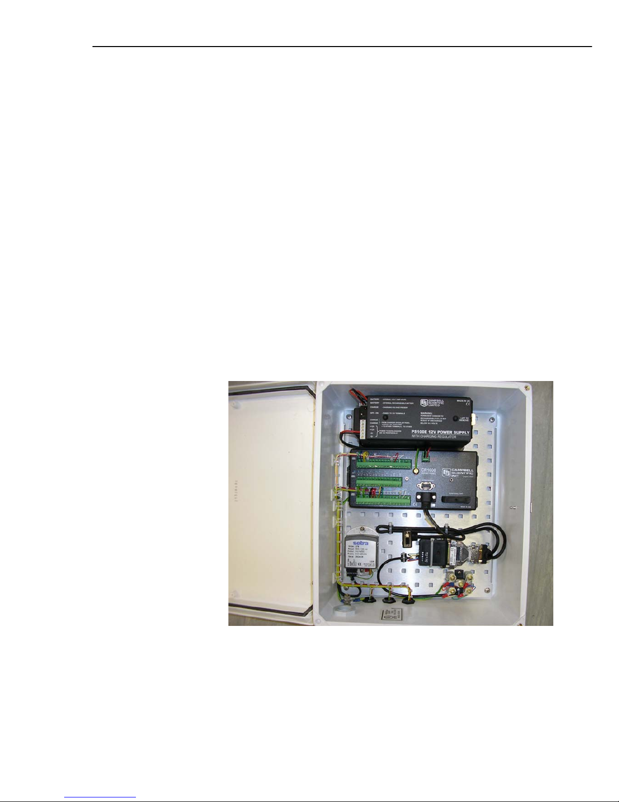
Figure 1 Typical Installation of CS-SRM in logger enclosure
2
Page 9

User Guide
3. Installation
Use the SC932C 9-Pin to RS232-DCE Interface between the RAD-SRM and the
datalogger.
4-Wire Telephone Line
or 2 Twisted Pairs
RAD-SP
(if required)
RAD-SRM
Modem
SC25/
SC25AT
Cable
PC
SC932
Datalogger
RAD-SP
(if required)
RAD-SRM
Modem
Datalogger
CS I/O Port
SC932C
Figure 2 Block Diagram of CS-SRM Installation
Install the modems as follows:
1. Set the DCE/DTE switch in the RAD-SRM to DCE. (This is the default
setting and all CS-SRM modems are supplied with the switch in this
position.) To gain access to this switch and the line interface terminal block,
separate the two halves of the plastic cover by pressing the marked places on
the sides starting at the cable end.
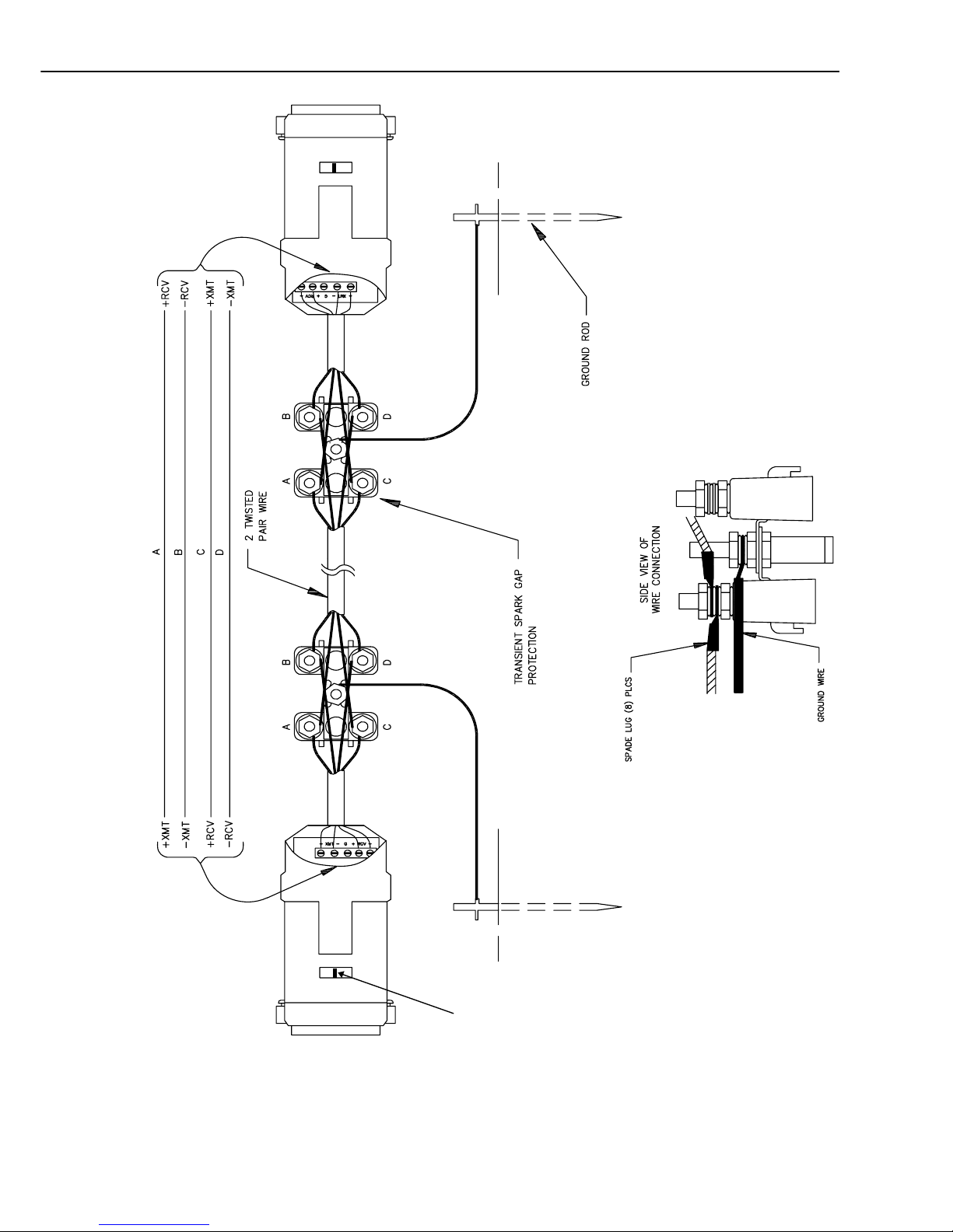
2. Select a suitable cable with two twisted pairs (see Section 4).
3. Connect the four conductors to the screw terminal block, with the transmit
pair connected to the terminals labelled ‘XMT’ and the receive pair to the
terminals labelled ‘RCV’. (See Figure 2; note that the wires labelled A and B
are one twisted pair of the cable, and the wires labelled C and D are
the other twisted pair.) A ground terminal is provided to connect the cable
shield (if present) at one end of the link only.
It is vital that the +XMT and -XMT terminals on one modem are connected
to the +RCV and -RCV terminals, respectively, on the other modem.
NOTE
4. Transients induced on the communication line may damage electronic
equipment connected at either end of the line. To decrease the chances of
damage, install earthed surge protectors as shown in Figure 2. Suitable
protectors are supplied in the CS-SRM package (model RAD-SP). The wiring
is straight through such that pin to pin continuity exists between the two
modems.
If the modems are installed entirely within a building the surge protectors
are not needed, unless the cable length exceeds 200m. Campbell Scientific
will not accept any warranty claims where damage to the CS-SRM has
occurred because the recommended surge protectors were not used.
NOTE
3
Page 10

CS-SRM Short Range Modem Package
5. Close the unit by pressing the two halves of the cover together. Connect one
modem directly to the RS232 port on the computer and connect the other to
the SC932C interface.
6. Referring to the SC932C manual, check that its internal jumpers are set in
the correct position for use with the CS-SRM modem.
7. This modem requires no specific set up in the latest version of PC400 or
LoggerNet, as the software will be aware of its presence.
3.1 Connection to a Remote Printer
Please refer to the SC932C Manual for details of connection to a remote printer.
3.2 Protection from Transients
The RAD-SP spark-gaps provide protection both for the datalogger
and RAD-SRM units from induced voltage transients in the
interconnecting cable. Please be aware that the RAD-SRM linked to
the computer can still be damaged by transients coming from the
PC, and in such circumstances considerable damage is also often
done to the PC itself. These transients can come from the AC power
lines to the PC or its peripherals and/or connections to other remote
peripherals (e.g. via network links) and are typically caused when
lightning strikes overhead power lines. As the RAD-SP units and the
datalogger protection devices act as low resistance clamps to
ground, the PC may offer the path of least resistance to ground
compared to other equipment.
CAUTION
To protect the PC and the RAD-SRM from this type of damage fit
the power supply lines to the PC with good quality surge arrestors.
These should also be fitted to any network or serial connections to
other devices. Please contact your computer dealer for the supply of
such devices.
4
Page 11
User Guide
DCE/DTE Switch
Figure 3 Wiring and Installation of Surge Protectors for a Typical CS-SRM Setup
5
Page 12

CS-SRM Short Range Modem Package
4. Operating Distance
The distance over which the CS-SRM will operate is determined by three factors:
baud rate, conductor size and cable quality. Table 1 shows the variation of
maximum transmission distance with baud rate and conductor size for a good
quality cable.
Table 1 Maximum Transmission Distance
Baud Rate 19 AWG 24 AWG 26 AWG
(0.9mm) (0.5mm) (0.44mm)
19200 5.0km 2.0km 1.5km
9600 10.0km 4.5km 3.0km
4800 11.5km 5.0km 4.0km
2400/1200 12.0km 5.5km 4.0km
For distances up to 100m, twin twisted pair cable such as that used for normal
telephone installations will suffice. For greater distances, an overall screened twin
twisted pair such as Belden type 9302 is required. If you need to operate RADSRMs at maximum range and baud rate, then a low loss cable such as IBM cable
reference 4716748 is suggested; if the cable has to be buried then Belden 1048A
or IBM cable reference 4716734 should be used.
TD
RD
RTS
CTS
DSR
DCD
DTR
2
3
4
5
6
8
20
XMT Pair
RCV Pair
V+
V+
TD
RD
RTS
CTS
DSR
DCD
DTR
2
3
4
5
6
8
20
RCV Pair
XMT Pair
V+
V+
Switch set to
DCE Position
Switch set to
DTE Position
Figure 4 Switch Settings for DCE/DTE
6
Page 13

Page 14

CAMPBELL SCIENTIFIC COMPANIES
Campbell Scientific, Inc. (CSI)
815 West 1800 North
Logan, Utah 84321
UNITED STATES
www.campbellsci.com
info@campbellsci.com
Campbell Scientific Africa Pty. Ltd. (CSAf)
PO Box 2450
Somerset West 7129
SOUTH AFRICA
www.csafrica.co.za
sales@csafrica.co.za
Campbell Scientific Australia Pty. Ltd. (CSA)
PO Box 444
Thuringowa Central
QLD 4812 AUSTRALIA
www.campbellsci.com.au
info@campbellsci.com.au
Campbell Scientific do Brazil Ltda. (CSB)
Rua Luisa Crapsi Orsi, 15 Butantã
CEP: 005543-000 São Paulo SP BRAZIL
www.campbellsci.com.br
suporte@campbellsci.com.br
Campbell Scientific Canada Corp. (CSC)
11564 - 149th Street NW
Edmonton, Alberta T5M 1W7
CANADA
www.campbellsci.ca
dataloggers@campbellsci.ca
Campbell Scientific Ltd. (CSL)
Campbell Park
80 Hathern Road
Shepshed, Loughborough LE12 9GX
UNITED KINGDOM
www.campbellsci.co.uk
sales@campbellsci.co.uk
Campbell Scientific Ltd. (France)
Miniparc du Verger - Bat. H
1, rue de Terre Neuve - Les Ulis
91967 COURTABOEUF CEDEX
FRANCE
www.campbellsci.fr
info@campbellsci.fr
Campbell Scientific Spain, S. L.
Psg. Font 14, local 8
08013 Barcelona
SPAIN
www.campbellsci.es
info@campbellsci.es
Campbell Scientific Ltd. (Germany)
Fahrenheitstrasse13, D-28359 Bremen
GERMANY
www.campbellsci.de
info@campbellsci.de
Please visit www.campbellsci.com to obtain contact information for your local US or International representative.
 Loading...