

Page 1

INSTRUCTION MANUAL
CRVW3 3-Channel
Copyright © 2015
Campbell Scientific, Inc.
Vibrating-Wire Datalogger
Preliminary: 1/30/15
Page 2

Page 3

Limited Warranty
“Products manufactured by CSI are warranted by CSI to be free from defects in
materials and workmanship under normal use and service for twelve months
from the date of shipment unless otherwise specified in the corresponding
product manual. (Product manuals are available for review online at
www.campbellsci.com.) Products not manufactured by CSI, but that are resold
by CSI, are warranted only to the limits extended by the original manufacturer.
Batteries, fine-wire thermocouples, desiccant, and other consumables have no
warranty. CSI’s obligation under this warranty is limited to repairing or
replacing (at CSI’s option) defective Products, which shall be the sole and
exclusive remedy under this warranty. The Customer assumes all costs of
removing, reinstalling, and shipping defective Products to CSI. CSI will return
such Products by surface carrier prepaid within the continental United States of
America. To all other locations, CSI will return such Products best way CIP
(port of entry) per Incoterms ® 2010. This warranty shall not apply to any
Products which have been subjected to modification, misuse, neglect, improper
service, accidents of nature, or shipping damage. This warranty is in lieu of all
other warranties, expressed or implied. The warranty for installation services
performed by CSI such as programming to customer specifications, electrical
connections to Products manufactured by CSI, and Product specific training, is
part of CSI's product warranty. CSI EXPRESSLY DISCLAIMS AND
EXCLUDES ANY IMPLIED WARRANTIES OF MERCHANTABILITY
OR FITNESS FOR A PARTICULAR PURPOSE. CSI hereby disclaims,
to the fullest extent allowed by applicable law, any and all warranties and
conditions with respect to the Products, whether express, implied or
statutory, other than those expressly provided herein.”
Page 4

Assistance
Products may not be returned without prior authorization. The following
contact information is for US and international customers residing in countries
served by Campbell Scientific, Inc. directly. Affiliate companies handle
repairs for customers within their territories. Please visit
www.campbellsci.com to determine which Campbell Scientific company serves
your country.
To obtain a Returned Materials Authorization (RMA), contact CAMPBELL
SCIENTIFIC, INC., phone (435) 227-9000. After an application engineer
determines the nature of the problem, an RMA number will be issued. Please
write this number clearly on the outside of the shipping container. Campbell
Scientific’s shipping address is:
CAMPBELL SCIENTIFIC, INC.
RMA#_____
815 West 1800 North
Logan, Utah 84321-1784
For all returns, the customer must fill out a “Statement of Product Cleanliness
and Decontamination” form and comply with the requirements specified in it.
The form is available from our web site at www.campbellsci.com/repair. A
completed form must be either emailed to repair@campbellsci.com or faxed to
(435) 227-9106. Campbell Scientific is unable to process any returns until we
receive this form. If the form is not received within three days of product
receipt or is incomplete, the product will be returned to the customer at the
customer’s expense. Campbell Scientific reserves the right to refuse service on
products that were exposed to contaminants that may cause health or safety
concerns for our employees.
Page 5

Precautions
DANGER — MANY HAZARDS ARE ASSOCIATED WITH INSTALLING, USING, MAINTAINING, AND WORKING ON OR AROUND
TRIPODS, TOWERS, AND ANY ATTACHMENTS TO TRIPODS AND TOWERS SUCH AS SENSORS, CROSSARMS, ENCLOSURES,
ANTENNAS, ETC. FAILURE TO PROPERLY AND COMPLETELY ASSEMBLE, INSTALL, OPERATE, USE, AND MAINTAIN TRIPODS,
TOWERS, AND ATTACHMENTS, AND FAILURE TO HEED WARNINGS, INCREASES THE RISK OF DEATH, ACCIDENT, SERIOUS
INJURY, PROPERTY DAMAGE, AND PRODUCT FAILURE. TAKE ALL REASONABLE PRECAUTIONS TO AVOID THESE HAZARDS.
CHECK WITH YOUR ORGANIZATION'S SAFETY COORDINATOR (OR POLICY) FOR PROCEDURES AND REQUIRED PROTECTIVE
EQUIPMENT PRIOR TO PERFORMING ANY WORK.
Use tripods, towers, and attachments to tripods and towers only for purposes for which they are designed. Do not exceed design
limits. Be familiar and comply with all instructions provided in product manuals. Manuals are available at www.campbellsci.com or
by telephoning (435) 227-9000 (USA). You are responsible for conformance with governing codes and regulations, including safety
regulations, and the integrity and location of structures or land to which towers, tripods, and any attachments are attached. Installation
sites should be evaluated and approved by a qualified engineer. If questions or concerns arise regarding installation, use, or
maintenance of tripods, towers, attachments, or electrical connections, consult with a licensed and qualified engineer or electrician.
General
• Prior to performing site or installation work, obtain required approvals and permits. Comply
with all governing structure-height regulations, such as those of the FAA in the USA.
• Use only qualified personnel for installation, use, and maintenance of tripods and towers, and
any attachments to tripods and towers. The use of licensed and qualified contractors is
highly recommended.
• Read all applicable instructions carefully and understand procedures thoroughly before
beginning work.
• Wear a hardhat and eye protection, and take other appropriate safety precautions while
working on or around tripods and towers.
• Do not climb tripods or towers at any time, and prohibit climbing by other persons. Take
reasonable precautions to secure tripod and tower sites from trespassers.
• Use only manufacturer recommended parts, materials, and tools.
Utility and Electrical
• You can be killed or sustain serious bodily injury if the tripod, tower, or attachments you are
installing, constructing, using, or maintaining, or a tool, stake, or anchor, come in contact
with overhead or underground utility lines.
• Maintain a distance of at least one-and-one-half times structure height, 20 feet, or the
distance required by applicable law, whichever is greater, between overhead utility lines and
the structure (tripod, tower, attachments, or tools).
• Prior to performing site or installation work, inform all utility companies and have all
underground utilities marked.
• Comply with all electrical codes. Electrical equipment and related grounding devices should
be installed by a licensed and qualified electrician.
Elevated Work and Weather
• Exercise extreme caution when performing elevated work.
• Use appropriate equipment and safety practices.
• During installation and maintenance, keep tower and tripod sites clear of un-trained or non-
essential personnel. Take precautions to prevent elevated tools and objects from dropping.
• Do not perform any work in inclement weather, including wind, rain, snow, lightning, etc.
Maintenance
• Periodically (at least yearly) check for wear and damage, including corrosion, stress cracks,
frayed cables, loose cable clamps, cable tightness, etc. and take necessary corrective actions.
• Periodically (at least yearly) check electrical ground connections.
WHILE EVERY ATTEMPT IS MADE TO EMBODY THE HIGHEST DEGREE OF SAFETY IN ALL CAMPBELL SCIENTIFIC PRODUCTS,
THE CUSTOMER ASSUMES ALL RISK FROM ANY INJURY RESULTING FROM IMPROPER INSTALLATION, USE, OR
MAINTENANCE OF TRIPODS, TOWERS, OR ATTACHMENTS TO TRIPODS AND TOWERS SUCH AS SENSORS, CROSSARMS,
ENCLOSURES, ANTENNAS, ETC.
Page 6

Page 7

Table of Contents
PDF viewers: These page numbers refer to the printed version of this document. Use the
PDF reader bookmarks tab for links to specific sections.
1. Introduction ................................................................. 1
2. Cautionary Statements ............................................... 2
3. Initial Inspection ......................................................... 3
4. Quickstart .................................................................... 4
5. Overview ...................................................................... 5
5.1 Measurement Theory ........................................................................... 5
5.2 About This Manual .............................................................................. 7
6. Specifications ............................................................. 8
7. Installation ................................................................... 9
7.1 Individual Devices and Radio Considerations ................................... 10
7.2 Software Requirements ...................................................................... 10
8. Installation of Individual CRVW3 Stations .............. 10
8.1 Lab Connection and Configuration .................................................... 11
8.1.1 Preparing the Windows Computer (PC) ..................................... 11
8.1.1.1 Device Configuration Utility (DevConfig) ....................... 11
8.1.1.2 Install the CRVW3 USB Driver ....................................... 12
8.1.1.3 Network Planner ............................................................... 12
8.1.2 Wiring Temporary Sensors to the CRVW3 ................................ 13
8.1.3 Providing Temporary Power to the CRVW3 .............................. 15
8.1.4 Connecting to the CRVW3 ......................................................... 15
8.1.5 Configuring the CRVW3 ............................................................ 18
8.1.5.1 Key Settings ..................................................................... 18
8.1.5.2 Managing Changes to Settings ......................................... 21
8.1.6 Testing the Measurement Operation of the CRVW3 .................. 22
8.1.7 Validating Radio Connectivity in the Lab .................................. 24
8.1.7.1 Configuring the RF450 Radio .......................................... 25
8.1.7.2 Configuring the CRVW3-RF451 ..................................... 25
8.1.7.3 Using DevConfig to Connect to the CRVW3-RF451
Over the Radio .............................................................. 26
8.2 Field Deployment of the CRVW3 ...................................................... 26
8.2.1 Connecting Sensors to the CRVW3 ............................................ 27
8.2.2 Providing Power to the CRVW3 ................................................. 29
8.2.2.1 Alkaline D-Cell Option (–ALK) ...................................... 29
8.2.2.2 Rechargeable Battery Option (–RC) ................................ 31
8.2.2.3 Grid Power ....................................................................... 32
8.2.3 Humidity Monitoring and Control .............................................. 33
8.2.4 Mounting the CRVW3 Enclosure ............................................... 33
i
Page 8

Table of Contents
8.2.5 Installing the CRVW3 Antenna ................................................. 34
8.2.6 Connecting the CRVW3 Electrical System to Earth Ground ..... 35
8.2.7 Validating and Fine-Tuning CRVW3 Settings ........................... 35
8.2.8 Confirming CRVW3 Sensor Measurement Operation ............... 36
8.2.8.1 LED Operation ................................................................ 36
8.2.8.2 Validation with DevConfig .............................................. 38
8.2.9 Validating CRVW3 Radio Operation ......................................... 40
8.2.10 Sealing the CRVW3 Enclosure .................................................. 40
8.3 On-site Manual Data Collection ........................................................ 41
9. Radio Networks ......................................................... 41
9.1 Simple Radio Network Definition ..................................................... 42
9.2 Simple Network Installation Overview ............................................. 43
9.3 CRVW3-RF451 Simple Network Installation ................................... 43
9.3.1 Deploying CRVW3 End-node Stations, Confirming Radio
Connectivity ............................................................................ 44
9.3.2 Base Station Installation and Validation .................................... 44
9.3.3 Configuring LoggerNet for Connectivity and Scheduled
Collection ................................................................................ 45
10. Complex (Large) Radio Networks ............................ 46
10.1 Radio Network Station Types ........................................................... 46
10.1.1 LoggerNet Computer Station ..................................................... 46
10.1.2 Base Radio Station ..................................................................... 47
10.1.3 CRVW3 End-node Station ......................................................... 48
10.1.4 CRVW3 Repeater Station .......................................................... 48
10.1.5 Dedicated Repeater Station ........................................................ 48
10.1.6 Aggregating Datalogger Station ................................................. 49
10.2 Planning the Radio Network ............................................................. 49
10.2.1 Sensor Planning .......................................................................... 51
10.2.2 Planning for CRVW3 End-node Stations ................................... 52
10.2.3 Repeater Planning ...................................................................... 53
10.2.4 LoggerNet Station Planning ....................................................... 53
10.2.5 Planning the Base Station ........................................................... 54
10.2.6 Planning RF451 Radio Networks ............................................... 55
10.2.6.1 Base Station Design for RF451 Radio Networks ............ 56
10.2.7 Plan Validation and Hardware Procurement .............................. 57
10.2.7.1 Pre-procurement Field Visits ........................................... 57
10.2.7.2 Plan Validation with Others ............................................. 58
10.2.7.3 Hardware Procurement .................................................... 58
10.3 Deployment Strategy ......................................................................... 58
10.3.1 Radio Network Lab Validation .................................................. 58
10.3.2 Field Deployment Considerations .............................................. 59
10.4 Deployment of CRVW3 Radio Stations ............................................ 60
10.4.1 CRVW3-RF451 Deployment ..................................................... 60
10.5 Base Station Deployment .................................................................. 61
10.5.1 Base Station on the RF451 Network .......................................... 62
10.6 Repeater Station Deployment ............................................................ 63
10.6.1 Repeaters on RF451 Networks ................................................... 63
10.7 LoggerNet Configuration .................................................................. 64
10.7.1 Physical Connection to the Base Station .................................... 64
10.7.2 Configuring the Network Map of LoggerNet ............................. 64
10.7.3 Connecting to CRVW3 Stations ................................................ 69
10.7.4 Setting up Automatic Data Collection ........................................ 71
ii
Page 9

11. Operation of CRVW3 Networks ............................... 71
11.1 Monitoring Automatic Data Collection .............................................. 72
11.2 Manual Data Collection ..................................................................... 74
11.2.1 Manual Data Collection From the LoggerNet Station ................ 74
11.2.2 Manual Data Collection at the CRVW3 Site .............................. 75
11.3 Station Health Monitoring ................................................................. 76
11.4 Processing Collected Data ................................................................. 77
11.4.1 Monitoring Data Influx Using Real-time Displays ..................... 77
11.4.2 Analyzing and Publishing Historical Data .................................. 77
12. Maintenance of CRVW3 Networks ........................... 79
12.1 CRVW3 Maintenance with LoggerNet .............................................. 79
12.1.1 Battery Monitoring ..................................................................... 79
12.1.2 Sensor Spectrum Checks ............................................................. 80
12.1.3 Adjusting Device Settings ........................................................... 82
12.2 CRVW3 On-site Maintenance Visits ................................................. 83
13. Troubleshooting CRVW3 Networks ........................ 84
13.1 Troubleshooting Problems Remotely Using LoggerNet .................... 85
13.2 Troubleshooting Problems by Visiting the CRVW3 Site ................... 85
Appendices
Updating CRVW3 Firmware ................................... A-1
A.
B. Terminal Mode from Connect Screen or
DevConfig .............................................................. B-1
C. Aggregating Dataloggers ....................................... C-1
C.1 Aggregator Station Configuration .................................................... C-1
C.2 Programming the Aggregator ........................................................... C-2
D. GetDataRecord Sample Program .......................... D-1
E. Engineering Output and Calibration ..................... E-1
E.1 Engineering Output .......................................................................... E-1
E.2 Calibration of Sensors ...................................................................... E-2
Figures
1-1. The CRVW3 3-Channel Vibrating-Wire Datalogger ........................... 1
3-1. Contents of the enclosure manufacturer parts bag ............................... 3
3-2. CRVW3 with the –UM mounting option ............................................. 4
5-1. Basic Parts of the CRVW3 ................................................................... 5
5-2. CRVW3 Cable Connection and Entry Points ...................................... 5
5-3. Internal View of a Typical Vibrating-Wire Piezometer Sensor ........... 6
5-4. Time-Series and Frequency Response of a Vibrating-Wire Sensor ..... 7
8-1. Wiring Panel of the CRVW3 ............................................................. 14
8-2. Typical Vibrating-Wire Sensor Lead Colors and Connections .......... 14
Page 10

Table of Contents
8-3. Power Source Connection to the CRVW3 Charge Terminals ........... 15
8-4. CRVW3 USB Connection Location .................................................. 16
8-5. Typical Vibrating-Wire Sensor Lead Colors and Connections ......... 28
8-6. CRVW3 Cable Connection and Entry Points .................................... 28
8-7. Wiring Panel of the CRVW3 ............................................................. 29
8-8. –ALK Battery Pack Connector Cable and CRVW3 Battery
Connection ..................................................................................... 30
8-9. Bumpers Used to Secure the -ALK Battery Pack .............................. 30
8-10. Power Source Connection to the CRVW3 Charge Terminals ........... 32
8-11. –RC Battery Connector Cable and CRVW3 Battery Connection ..... 32
8-12. CRVW3 with the –UM mounting option .......................................... 33
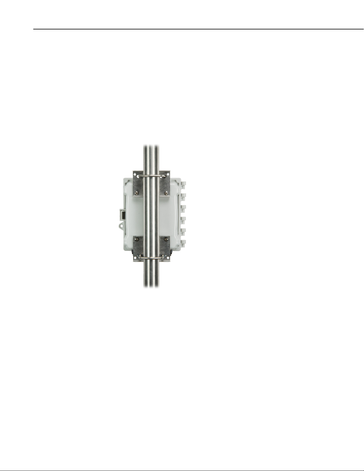
8-13. Proper Field-Installed Orientation of the CRVW3 ............................ 34
8-14. Properly Weather-proofed Antenna Cable Connection with Surge
Protection ....................................................................................... 35
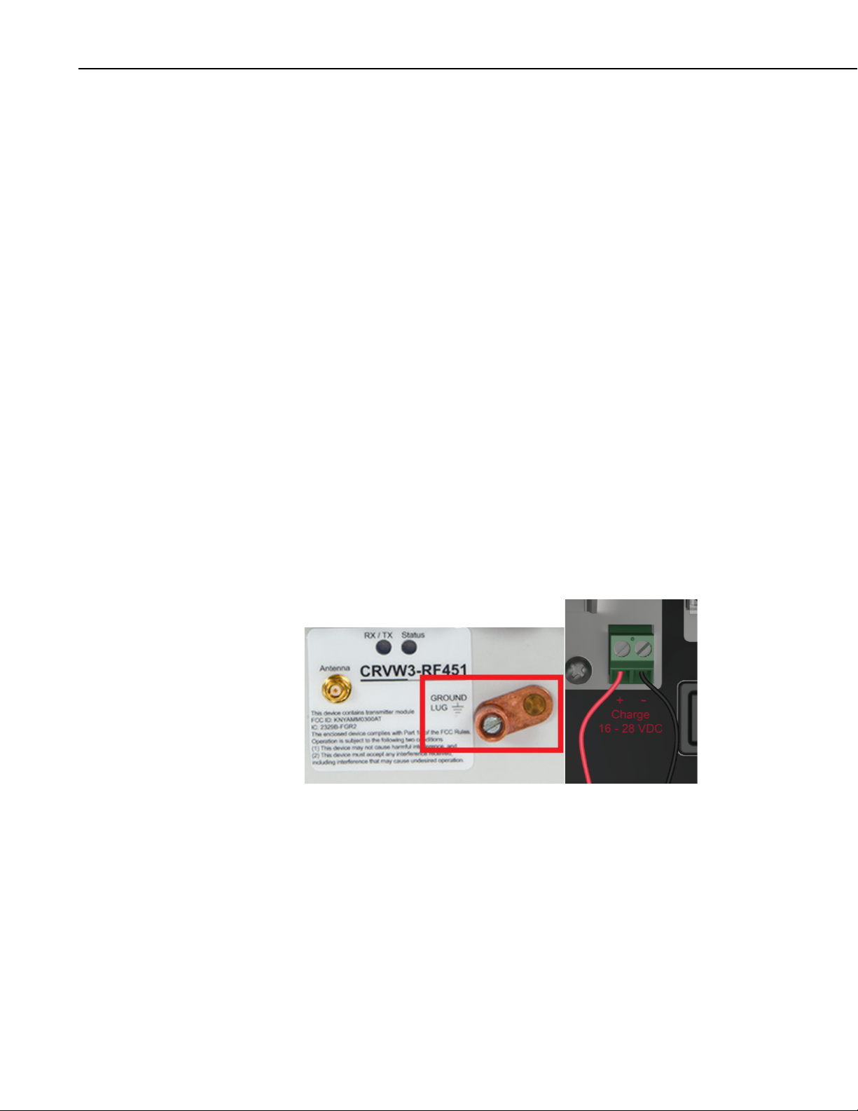
8-15. CRVW3 Ground Lug Location ......................................................... 35
8-16. LED Viewing Locations on the CRVW3 .......................................... 37
8-17. CRVW3 Latch Closure and Lock Location ...................................... 41
9-1. CRVW3 Radio Network ................................................................... 42
9-2. RF451 Network Base Station Configured for Remote LoggerNet
Connectivity ................................................................................... 44
10-1. CRVW3 Radio Network and Base Station Operation ....................... 47
10-2. CRVW3 Collected Data Flow ........................................................... 49
10-3. Sensor Side and LoggerNet Side of a CRVW3 Network .................. 50
10-4. Each Sensor Connects to a CRVW3 ................................................. 52
Table
8-1. CRVW3 LED Behavior..................................................................... 37
iv
Page 11

CRVW3 3-Channel Vibrating-Wire
Datalogger
1. Introduction
The CRVW3 is a datalogger (Campbell recorder) that measures and stores
readings from up to three vibrating-wire sensors. A temperature measurement
(usually obtained from a thermistor built-in to the sensor) is also available for
each of these three channels. Standard, single-coil-circuit vibrating-wire
sensors are supported (purchased separately). Common vibrating-wire
measurements include water depth (pressure or column height), strain of
structural members, loading, crack/gap extension, earth pressure, and tilt.
FIGURE 1-1. The CRVW3 3-Channel Vibrating-Wire Datalogger
The use of patented VSPECT™ technology helps to eliminate unwanted noise
interference and results in high-resolution output. Measurements may be taken
as often as once every 1 to 3 seconds (1 second per active channel) and as
infrequently as once per day. Measurement history is preserved on the device
enabling data collection at reasonable intervals, and protecting against data loss
due to periods of intermittent radio connectivity.
Each CRVW3 is packaged inside a protective enclosure. On-board power
support for a rechargeable battery (including a built-in charge regulator) or
non-rechargeable D-cells is included. Built-in radio options, including repeater
capability, are available to enable the creation of wireless networks.
1
Page 12
CRVW3 3-Channel Vibrating-Wire Datalogger
Configuration of devices and automated data collection can be performed
remotely using the wireless options.
CRVW3 operation is controlled by software-configured settings made on the
device. No CRBasic programming is required. Frequency and temperature
measurements are obtained at the specified measurement interval. Optional
engineering output can be calculated using advanced settings.
Additional information about the CRVW3 (pn 30243) can be found on the
Campbell Scientific website:
www.campbellsci.com/crvw3
Before using the CRVW3, please refer to the following:
• Quick Deploy Guide
o a folded card stored within the CRVW3 that contains summarized
deployment and use instructions
• Section 2, Cautionary Statements
• Section 3, Initial Inspection
2. Cautionary Statements
• READ AND UNDERSTAND the Precautions section at the front of this
manual.
• DANGER: As with all electrical devices, ensure proper grounding using
the ground lug of the device. Observe polarity (+/–) markings on the
charge connector, and do not apply voltages over 28 V.
• Carefully install any solar panels, other power supply devices, antennae,
and cabling according to manufacturer recommendations. Use surge
suppression where possible. Consider the use of the Basic Grounding Kit
(pn 31163), the Bulkhead Surge Suppressor Kit (pn 31312), and Selfvulcanizing Shrink Tape (pn 21212).
2
• WARNING: Close the lid of the enclosure and secure the latch when the
CRVW3 is deployed. This will help avoid unwanted entry of water, and
provide isolation from other environmental factors. IP66 protection is
available when using the four screws provided by the enclosure
manufacturer to seal the lid properly. Wipe off any water from the outside
of the enclosure before opening the enclosure lid.
Page 13

When using multiple CRVW3 devices in an RF451 radio network
NOTE
NOTE
or in an RF407 radio network, it may be necessary to deploy an
RF450, RF451, or RF407 radio+modem device (in addition to
those built-in to the CRVW3) to operate as the base radio station
in the network. Please consult with your local Campbell Scientific
support representative regarding the use of radio options. Also
refer to Section
(Large) Radio Networks, for more information relating to the
design and configuration of radio networks.
3. Initial Inspection
Ensure that the following standard items were included with your shipment of
the CRVW3:
• USB 2.0 Cable Type A Male to Micro B Male (pn 27555)
• Flat-bladed Screwdriver (pn 1113)
• Quick Deploy Guide (folded card, pn 31174)
• Desiccant Bag (pn 4905)
• Humidity Indicator Card w/ Mounting Tape (pn 28878)
• Original Enclosure Manufacturer Parts bag including (4) Lid-securing
CRVW3 3-Channel Vibrating-Wire Datalogger
9, Radio Networks, and Section 10, Complex
Screws
Most of these items are shipped from the factory inside a bag
stored within the enclosure.
The contents of the enclosure manufacturer parts bag are shown in FIGURE
3-1.
FIGURE 3-1. Contents of the enclosure manufacturer parts bag
3
Page 14
CRVW3 3-Channel Vibrating-Wire Datalogger
Examine the outside label on the device to ensure that the correct
communication option was provided (–RF451 radio, –RF407 radio, No radio).
Confirm that the appropriate battery option is installed within the CRVW3
enclosure. For the –ALK option, this is an 8-cell battery pack along with 8
D-cell alkaline batteries. For the –RC option, this is a single rechargeable leadacid 7 Ahr battery. If you received a CRVW3 with the –RC option, you should
begin charging your rechargeable battery as soon as possible after receiving
your shipment. See Section 8.1.3, Providing Temporary Power to the CRVW3,
for details about how this is done.
If the –UM mounting option was selected, ensure that the corresponding
mounting hardware was included with your shipment.
4. Quickstart
4
FIGURE 3-2. CRVW3 with the –UM mounting option
Find the packing list that came with your shipment and ensure that all other
related accessories included in your order are present and in good condition.
Typical accessories include solar panels, other power equipment, antennae,
cabling, grounding kits, and related items. Thoroughly check the packaging
material for items that may be trapped inside. In case of damage, file claims
with the shipping company. Contact Campbell Scientific to facilitate repair or
replacement of damaged items.
For Quickstart information, refer to the Quick Deploy Guide included with
each CRVW3 as a folded card inside the enclosure (pn 31174). You can also
view and download the Quick Deploy Guide from the Campbell Scientific
website:
s.campbellsci.com/documents/us/manuals/crvw3-quick-deploy-guide.pdf
Page 15

5. Overview
CRVW3 3-Channel Vibrating-Wire Datalogger
The CRVW3 is a rugged, field-ready datalogger for measuring vibrating-wire
sensors. It provides built-in power options, including a charge regulator that
enables direct solar panel connections. Built-in radio options are available to
enable wireless communications, and the system comes inside an
environmentally protective enclosure as a standard option. The basic parts of
the CRVW3 are shown in FIGURE 5-1.
FIGURE 5-1. Basic Parts of the CRVW3
5.1 Measurement Theory
The CRVW3 uses Campbell Scientific VSPECT™ technology (U.S. Patent
No. 7,779,690 ) to measure standard, single-coil-circuit vibrating-wire sensors.
FIGURE 5-2. CRVW3 Cable Connection and Entry Points
5
Page 16

CRVW3 3-Channel Vibrating-Wire Datalogger
A vibrating-wire sensor is designed by its manufacturer so that its output
corresponds to changes of the phenomenon in the environment being
measured. This is done by converting environmental changes into changes of
the tension on a suspended metal wire which is located inside the sensor. The
wire’s natural frequency changes as the tension changes, therefore a change in
frequency may be detected as changes in the measured phenomenon. A
magnetic coil circuit is placed near the suspended wire and senses the motion
of the wire by picking up the changes in the magnetic field caused by wire
vibrations.
To measure a vibrating-wire sensor, three main steps are taken by the
measurement system: 1) Electrical energy is inserted into the coil circuit,
creating a changing magnetic field that excites (plucks, or inserts energy into)
the wire. 2) The excitation terminates so that the wire is left to vibrate at its
characteristic resonant frequency (natural frequency). The coil circuit is used
to electrically capture the motion of the wire’s vibrations during this stage.
3) The measurement system processes the time-series waveform captured from
the coil to assess the frequency of the wire’s vibration. The basic output of a
vibrating-wire sensor is frequency in Hz. Conversion from frequency to
engineering units is possible based on a knowledge of how the sensor operates,
and that is provided by the sensor manufacturer.
FIGURE 5-3. Internal View of a Typical Vibrating-Wire Piezometer
Sensor
The CRVW3 excites vibrating-wire sensors with a swept excitation
(frequency-rich) waveform. The lowest frequency and highest frequency used
in that excitation are customizable by the user. This frequency range represents
all expected natural frequencies that the sensor should produce, including those
expected when it measures the most extreme conditions in the environment
(highest and lowest frequencies). By exciting the sensor in only a certain
range, interference from unwanted signals on the wire is reduced. The level of
the excitation (12 V, 5 V, 2 V) can also be controlled by the user.
The patented VSPECT™ process uses frequency-domain analysis (including
the use of Fourier transforms), interpolation, and digital signal processing
(DSP) to identify and eliminate unwanted noise from the measurement, and
produces a very high resolution frequency output.
6
Page 17

CRVW3 3-Channel Vibrating-Wire Datalogger
FIGURE 5-4. Time-Series and Frequency Response of a Vibrating-
Wire Sensor
Since changes in temperature can impact the density of the vibrating-wire
element of the sensor, a slight change in frequency is expected on the sensor as
temperature changes occur. To compensate for this effect, many vibrating-wire
sensors contain a built-in thermistor or other resistive temperature device. The
resistance of the device is measured and converted to temperature. The
temperature at the time of measurement is recorded and can then be used
together with the frequency reading to calculate the value of the output
phenomenon in engineering units (i.e., measured value given with its
dimensions or units of measure).
5.2 About This Manual
Please study the remaining sections of this manual to obtain maximum benefit
from your CRVW3 dataloggers.
Section 6, Specifications, contains key specifications relevant to the
measurement and use of the CRVW3.
Section 7, Installation, introduces the main installation issues applicable to the
CRVW3.
Section 8, Installation of Individual CRVW3 Stations, focuses on the
installation of individual CRVW3 stations.
7
Page 18

CRVW3 3-Channel Vibrating-Wire Datalogger
Section 9, Radio Networks, and Section 10, Complex (Large) Radio Networks,
discuss the planning and implementation of networks containing multiple
CRVW3 stations that communicate with each other using radio telemetry.
Section 11, Operation of CRVW3 Networks, Section 12, Maintenance of
CRVW3 Networks, and Section 13, Troubleshooting CRVW3 Networks, provide
guidance for the operation, maintenance, and troubleshooting required when
administering CRVW3 measurement systems.
Appendices are also provided containing supplemental information.
6. Specifications
Datalogger
Processor: ST ARM CORTEX-M4 (32-bit with
Data Storage: 16 MB serial flash, up to 420,000 records
Clock Accuracy: ±3 minutes per year
hardware FPU, running at 144 MHz)
(single channel), up to 160,000 records (3
channels)
Measurement
Interval Range: 1 s to 1 day
USB Micro B: Direct connect to PC (supplies power for
configuration and data collection), 2.0 full
speed, 12 Mbps
Configuration: Software configurable, no programming
required
Measurements
Channel Count: 3 vibrating wire (VW) and 3 thermistor/RTD
(temperature) measurements
Measurement Speed: 1 s per sensor (VW and temperature)
Vibrating Wire
Measurement
Excitation Options: 2 V (±1 V), 5 V (±2.5 V), 12 V (±6 V)
Measurement
(Frequency) Resolution: 0.001 Hz RMS (–40 to 70 °C)
Time-series
Basic Resolution: 24-bit ADC
Measurement Accuracy: ±0.005% of reading
8
Measurement Method: VSPECT (Spectral Analysis), U.S. Patent
No. 7,779,690, includes diagnostic data
Page 19

CRVW3 3-Channel Vibrating-Wire Datalogger
Temperature (Resistance)*
Measurement Method: Half-bridge ratiometric, 24-bit ADC, built-in
completion resistor 4.99 kΩ 0.1%
Resolution: 0.01 Ω RMS (–40 to +70 °C)
Accuracy: ±0.15% of reading (–40 to +70 °C)
Wireless Communications
–RF451 Option
Internal Radio Description: 1 W, 902 to 928 MHz license-free band,
frequency hopping spread spectrum radio
FCC ID: KNYAMM0300AT
IC: 2329B-FGR2
Radio Repeater: Devices with the –RF451 option can be
setup as a radio repeater
Power
Charge Terminal: 16 to 28 Vdc from solar panel or dc power
converter
7. Installation
Battery Options: Rechargeable 7 Ah or 8 D-cell alkaline
Physical
Weight: 4.2 kg (9.2 lb) with rechargeable battery, 3.0
kg (6.6 lb) with alkaline batteries
Operating
Temperature Range: –40 to 70 °C
Compliance: CE, RoHS
Enclosure Dimensions: 24.1 x 22.9 x 14.0 cm (9.5 x 9.0 x 5.5 in)
Weather-proof
Enclosure Rating: NEMA 4X (IP66) with proper use of cable
entry points
Enclosure Mounting: Stainless steel universal mount for pole/ wall
mount (optional) or plastic mounting tabs
(included)
* Thermistor or RTD resistance can be scaled to Temperature (°C) per manufacturer
specifications. The resulting temperature can be used as a correction factor for the
sensor’s output.
For summarized installation information, refer to the Quick Deploy Guide (pn
31174) included with each CRVW3 as a folded card inside the enclosure. You
can also view and download the Quick Deploy Guide from the Campbell
Scientific website:
s.campbellsci.com/documents/us/manuals/crvw3-quick-deploy-guide.pdf
9
Page 20

CRVW3 3-Channel Vibrating-Wire Datalogger
Campbell Scientific Field-Deployment Philosophy
Pre-configure and test your measurement system before taking it to the field.
Issues that are unresolved before placing instrumentation in the field will
usually be more difficult to resolve once in-field. Campbell Scientific
equipment and software are among the best available, but the integration
process can be demanding and involves trial and error; contingencies should be
developed to address possible problems. Perform the bulk of the integration
work in a comfortable and dry location that has a communications link with
Campbell Scientific during regular business hours. If you are experienced with
field deployments, set aside at least a full day for pre-configuration work.
Otherwise, set aside three to seven days for system development before
traveling to the field.
7.1 Individual Devices and Radio Considerations
Each CRVW3 device can be deployed to the field as an independent data
collection station. Additionally, radio communication options are provided to
allow CRVW3 devices to communicate with each other, with repeater stations,
and with a base radio station. This enables CRVW3 devices to interact from
the field with LoggerNet software running in the lab or office, or other IThosted location. Automatic data collection (i.e., collection without technician
field visits) is one of the most useful benefits provided by a radio network
configuration of multiple CRVW3 devices.
When installing CRVW3 devices, consider the deployment issues for both
individual stations (Section 8, Installation of Individual CRVW3 Stations) and
also the planning and configuration of radio communications within a multiCRVW3 network (Section 9, Radio Networks, and Section 10, Complex
(Large) Radio Networks).
7.2 Software Requirements
To use the computer software described in this manual, you must have a
version that includes CRVW3 support. These software versions are:
• LoggerNet version 4.3 or higher (MS-Windows or Linux platforms)
• PC400 version 4.3 or higher (MS-Windows only)
• PC200W version 4.3 or higher (MS-Windows only)
• DevConfig version 2.10 or higher (MS-Windows only)
You should periodically check the Campbell Scientific website for updates to
these software packages, and also for updates to the firmware/OS of the
CRVW3:
www.campbellsci.com/downloads
8. Installation of Individual CRVW3 Stations
The installation of an individual CRVW3 station includes two critical steps:
10
1. Connecting with and configuring the CRVW3 device in the lab or
office (Section 8.1, Lab Connection and Configuration)
Page 21

CRVW3 3-Channel Vibrating-Wire Datalogger
NOTE
2. Deployment of the CRVW3 device to a permanent location in the
field (Section 8.2, Field Deployment of the CRVW3)
Both steps are usually performed on each device. In unusual situations, or
when installation personnel have sufficient deployment experience, it is
conceivable that step 1 could be omitted. When that step is bypassed, some of
its elements will still need to be performed at the field location. If a station is
deployed as an independent collection station (i.e., with no radio links), its data
can be manually collected using a USB cable connection from the CRVW3 to a
laptop or similar computer.
When deploying a system of multiple CRVW3 devices using
radio-based communication options (such as the CRVW3RF451), also refer to Section
9, Radio Networks.
8.1 Lab Connection and Configuration
When using a CRVW3 device in the lab or office, there are several key tasks to
perform. A Microsoft Windows-based laptop or desktop computer (Personal
Computer, i.e., PC) should be available. Electrical outlets or other power
options, as well as vibrating-wire sensors for testing the device should also be
on-hand. During this process, the proper software and drivers will be installed
on the PC, the device will be wired to one or more sensors, and then it will be
powered. A connection between the device and the PC will be established, the
device will be configured, and the device’s measurement operation will be
validated.
8.1.1 Preparing the Windows Computer (PC)
For CRVW3 lab operations, you will need a desktop or laptop computer
running Microsoft Windows. This document also refers to that computer as a
PC (Personal Computer). When installing software, you should have
administrative privileges on the account used to log in to the computer at
startup. Consider the benefits of configuring and using a laptop in the lab —
once it is configured, it can then be taken into the field to facilitate efficient
deployment of CRVW3 devices (see Section 8.2, Field Deployment of the
CRVW3).
8.1.1.1 Device Configuration Utility (DevConfig)
You should first install the Device Configuration Utility (a.k.a., DevConfig).
The CRVW3 requires version 2.10 or later of this software. If you have
installed LoggerNet 4.3, PC400 4.3, or PC200W 4.3 on your computer, then
this software is already available. This software is also available as a free
download from the Campbell scientific website
(www.campbellsci.com/downloads, www.campbellsci.com/19_1_9999_83).
Check the version of any previously installed DevConfig software to ensure it
is version 2.10 or later. If it is an earlier version, it will need to be upgraded
using a newer installation program. The installation program can also be found
on the Resource DVD which is included with most hardware orders shipped
from Campbell Scientific.
11
Page 22

CRVW3 3-Channel Vibrating-Wire Datalogger
NOTE
If you upgrade your LoggerNet, PC400, or PC200W software
from an earlier version to version 4.3, then version 2.10 of
DevConfig should automatically be installed during that process.
8.1.1.2 Install the CRVW3 USB Driver
In order to make a wired communications connection between the CRVW3 and
the PC, it is necessary to use a USB cable. This requires a driver to be installed
on Windows in order to operate correctly.
Start DevConfig, and then scroll down and highlight the CRVW Series device
and you will see a screen like this:
12
Install the USB driver by clicking on the link entitled “install the USB driver
onto your computer”.
8.1.1.3 Network Planner
If you have installed the LoggerNet software, you can use the Network Planner
tool to make network design decisions and configure devices before they are
deployed to the field. The Network Planner is found in the Tools section of the
LoggerNet toolbar.
Page 23

CRVW3 3-Channel Vibrating-Wire Datalogger
The Network Planner allows you to plan out which measurement stations,
repeater stations, and base station will be used in your deployed system. You
can place hardware device icons onto a canvas (with an optional background
graphic in place, such as map), and explore how connections are made between
each station. Many of the settings are automatically set by the software as each
device is added to the canvas (such as unique PakBus addresses). Details about
the computer running LoggerNet are also worked out. After a design is
complete, the Network Planner can be used to automatically configure each
device that is a part of the system. Using a checklist showing each device that
requires configuration (Configure Devices), screens similar to those found in
DevConfig are used to prepare each device for field use.
For more information about the Network Planner, refer to the LoggerNet
Manual, Section 4.3.
For more information about the design of radio telemetry networks, see Section
9, Radio Networks, and Section 10, Complex (Large) Radio Networks.
8.1.2 Wiring Temporary Sensors to the CRVW3
Wiring sensors temporarily to the CRVW3 is necessary while in the lab to
validate measurement operation. You can use the actual sensors (or similar)
that will be used when the device is deployed to the field. Consider that any
sensors connected in the lab may need to be disconnected from the CRVW3
when the system is transported to the field location.
When wiring sensors to the CRVW3, it is recommended that the device be
powered down. Note that this includes removing any USB cable that may be
connected, since a USB cable provides enough power for the device to operate
(for configuration or data collection purposes).
A vibrating-wire sensor may contain a built-in thermistor or other resistive
temperature measurement device. If so, it will have five wire leads. Sensors
without built-in temperature monitoring have only three leads. Refer to the
sensor manufacturer’s documentation to determine what sensor type you have.
13
Page 24

CRVW3 3-Channel Vibrating-Wire Datalogger
NOTE
FIGURE 8-1. Wiring Panel of the CRVW3
Two of the sensor leads are for the main vibrating-wire measurement, and they
are wired internally to the coil-circuit of the sensor. This connection is used
for both sensor excitation (energy input) and for reading out the current
measurement (measurement output). These two leads should be connected to
the two VW terminals on the CRVW3 corresponding to the desired
measurement channel. The shield wire should be connected to the ground
associated with that channel (located in between the VW terminals and the T
terminals). If the sensor has a built-in temperature measurement device, then
those two leads should be connected to the two T terminals.
Sensor manufacturers often color-code the leads so you can easily identify
which leads are for the coil-circuit and which are for the temperature device.
Polarity does not need to be considered when wiring the two leads for the VW
terminals and the two leads for the T terminals.
FIGURE 8-2. Typical Vibrating-Wire Sensor Lead Colors and
Connections
Use the provided screwdriver (pn 1113) to wire the leads securely into the
terminal blocks. Ensure a good connection between the metal lead and the
inside of the terminal.
If the built-in temperature device isn’t a thermistor, measure only
the resistance of the device in Ohms. If it is a thermistor that
follows the Steinhart-Hart conversion formula, then you have the
option to convert the thermistor resistance output into Degrees
Celsius. Refer to the sensor manual to know which kind of
temperature device you have.
14
Page 25

CRVW3 3-Channel Vibrating-Wire Datalogger
8.1.3 Providing Temporary Power to the CRVW3
To provide temporary power to the CRVW3 while in the lab, it is
recommended that you use pn 29796 (Power Supply 24 Vdc, 5 ft Cable). You
can also use any power supply with a 16 to 28 volt DC output. Connect the
power leads to the charge terminals located on the CRVW3.
FIGURE 8-3. Power Source Connection to the CRVW3 Charge
Terminals
If your CRVW3 uses the –ALK option, you can disconnect that power source
to preserve battery life while power is applied to the charge terminals. When
using the –RC option, you can leave the rechargeable battery connected and the
charge circuit will charge the battery while the device is powered. You can
also power the device through the terminals when no battery is present.
A USB cable will also provide power to the CRVW3. However, the USB
connection alone does not provide enough power to operate the radio or make
measurements. USB power should only be used to configure the device or to
collect data. A power source other than USB should be provided for the
CRVW3 to make measurements properly and to enable radio communications.
For CRVW3 devices with the radio option, the RX/TX LED is solid red when
only USB power is provided to remind the user that the radio is not operating.
The Status LED shows a red flash when no radio is used and only USB power
is provided to the device. Measurements made while powered only with USB
will result in NAN (invalid) for measurement output.
8.1.4 Connecting to the CRVW3
Before connecting to the CRVW3 via USB, you must ensure that the USB
driver is installed as described above. After the driver is installed on a
particular PC, it should be in-place for all future connections. Connect
pn 27555 USB cable (included with the CRVW3 shipment) between the PC
and the powered CRVW3.
15
Page 26

CRVW3 3-Channel Vibrating-Wire Datalogger
FIGURE 8-4. CRVW3 USB Connection Location
Start the Device Configuration Utility software (DevConfig). Find the CRVW
Series device item in the Datalogger category (subtree) and select it. If the
Show Device Type Categories item in the Options menu is not selected, the
devices will be listed alphabetically. Once selected, you should see a picture of
the CRVW3 and connection instructions as shown below:
16
Press the ellipsis button (…) next to the Communication Port box. This will
list available COM ports on your system. With the USB driver properly
installed, one of these items should include CRVWx in the name. Choose that
COM port and press OK. Now press the Connect button in the lower left
corner of the DevConfig window.
Page 27

CRVW3 3-Channel Vibrating-Wire Datalogger
After a few moments, you should see the Settings Editor and Main tabs for
the CRVW3 device, as shown here:
If you are having trouble when pressing Connect, refer to Section 13,
Troubleshooting CRVW3 Networks.
The top set of tabs should include: Settings Editor, Logger Control, Data
Monitor, Send OS, Troubleshoot, and Terminal. With the Settings Editor
tab selected, the tabs should include: Main, PakBus, Channel 1, Channel 2,
and Channel 3. When using the –RF451 option you should see Radio and
Radio Advanced tabs.
Ensure you have selected the Settings Editor and Main tabs. The Model
setting for your CRVW3 should be shown. This should show CRVW3–RF451
if you have the –RF451 communications option. If you have the –RF407
communications option, you should see the value CRVW3-RF407. For the
-NoRadio option, you should simply see CRVW3 for the model.
You can use the OS Version box to determine which version of the device’s
firmware (operating system) is currently loaded in the device. For details on
how to update the firmware of the device, see Appendix A, Updating CRVW3
Firmware.
The Serial Number box shows the factory serial number of your device. The
Company box should read as Campbell Scientific, Inc.
Choose the Logger Control tab. You should see the Station Time update once
every second. This behavior confirms that you have a good connection with
the CRVW3 device. You may update the device’s clock to match the clock on
the computer by using the Set Clock button.
17
Page 28
CRVW3 3-Channel Vibrating-Wire Datalogger
8.1.5 Configuring the CRVW3
Once you have successfully connected to the CRVW3 using DevConfig (see
above), you can configure the device. This is an important installation activity
that cannot be overlooked. Key settings must be configured before (or when) a
device is deployed to the field.
Use the Settings Editor tab that is available when DevConfig is connected to
make configurations to the CRVW3. The following sub-tabs will appear:
Main, PakBus, Channel 1, Channel 2, and Channel 3. For devices with the
–RF451 option, two additional sub-tabs will appear: Radio and Radio
Advanced.
Key settings whose values you should review and set are listed below. As you
place the cursor in the box for each setting, the frame in the lower right corner
of the DevConfig screen shows text that describes the setting and how it is used
(online help).
18
8.1.5.1 Key Settings
[TabName – SettingName]
Main- Station Name
You can give a name to each CRVW3 station and store it in the device. When
planning a network of multiple devices, station naming can assist you in the
organization of your system. (See Planning your Network in Section 10.2,
Planning the Radio Network.)
Main – Measurement interval
This setting specifies how often the CRVW3 should measure the sensors
connected to its active channels. The CRVW3 will repeatedly and
automatically make these measurements at this interval and store the results
until powered down, or re-configured.
Page 29

CRVW3 3-Channel Vibrating-Wire Datalogger
NOTE
NOTE
For 1 active channel the smallest (fastest) measurement interval is 1 second.
For two channels, 2 seconds is required, and for three channels, 3 seconds is
the smallest interval. The longest interval between measurements that can be
used is 24 hours.
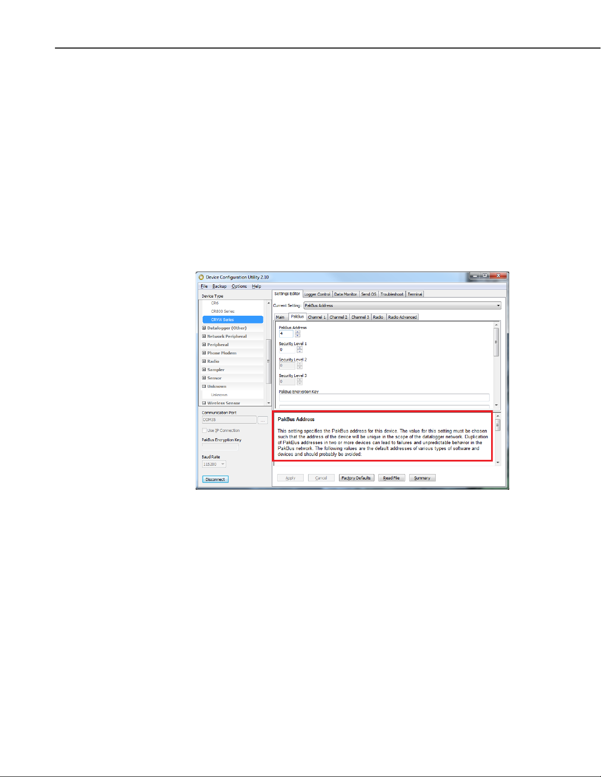
PakBus – PakBus Address
If multiple CRVW3 devices will communicate with each other in the field or
communicate to LoggerNet from the field, then each CRVW3 station requires a
unique PakBus address. You may wish to give a unique address to each
CRVW3 even if it currently won’t be deployed as part of a radio network in
case your communications usage on the device changes in the future. Set this
address to a value between 1 and 3999. Addresses between 4000 and 4094 are
reserved for use by specialized PakBus server tools such as LoggerNet or
DevConfig.
When deploying multiple devices to the field, plan carefully so that no two
devices share the same address.
The Network Planner can be used to manage PakBus Addresses
and ensure that each device has a unique value for this setting.
PakBus – Is Router
Sometimes, a CRVW3 is not only used to make measurements, but it is also
used as a communications relay device in a radio network. This can extend the
spatial range of the network by allowing distant stations to communicate back
to a base station via multiple radio links or “hops”. When a CRVW3 station
performs these relay functions it is known as a radio repeater, and also
functions as a PakBus router. Set the Is Router setting to true when the
CRVW3 station will be used in this way.
Since a station configured as a router must communicate with
multiple remote stations, an omnidirectional antenna is usually
required instead of a directional antenna. For more information
about repeater stations and routing, refer to Section
10, Complex
(Large) Radio Networks.
Channel 1, Channel 2, Channel 3 – Name
Each measurement channel (sensor) can be given a name. This helps to
distinguish data from multiple sensors as it is stored in the final storage table
and eventually collected into data files by LoggerNet or other means.
Sometimes a name more descriptive than just the channel number is helpful.
Channel 1, Channel 2, Channel 3 – Enabled
This setting is used to specify whether the channel will be actively measured or
not. When set to False, any sensor connected to the channel will be ignored.
19
Page 30

CRVW3 3-Channel Vibrating-Wire Datalogger
Channel 1, Channel 2, Channel 3 – Excitation Voltage
This setting controls how much electrical excitation energy is inserted into the
vibrating-wire sensor just before being measured for its natural frequency. The
excitation waveform is a frequency-rich sweep, containing frequencies from
the lowest to the highest desired frequencies required for the sensor being
measured. The amplitude of the input sweep waveform is controlled by this
setting. Amplitudes of 2 V, 5 V, and 12 V can be selected. Longer cable
lengths between a sensor and the CRVW3 may require a higher voltage setting.
Sensors measured on a 3 second or shorter interval may require the lowest
(2 V) voltage setting to avoid loss of resolution.
Channel 1, Channel 2, Channel 3 – Begin Frequency
This setting controls the lower frequency boundary that is used for the
excitation sweep waveform. It also controls the high-pass digital filtering that
is used on the measurement of the sensor. Any frequency detected on the
sensor lower than this value will be ignored during processing.
Refer to your sensor documentation for guidance on what frequencies can be
expected from your sensor during both usual and extreme environmental
conditions. Sensors measured on a 3 second or shorter interval should use as
narrow of a window as possible (i.e., minimize the range between Begin
Frequency and End Frequency) to avoid a loss of resolution.
Channel 1, Channel 2, Channel 3 – End Frequency
This setting controls the higher frequency boundary that is used for the
excitation sweep waveform. It also controls the low-pass digital filtering that
is used on the measurement of the sensor. Any frequency detected on the
sensor higher than this value will be ignored during processing.
Channel 1, Channel 2, Channel 3 – Thermistor Enabled
Set this setting to True if you have connected a built-in resistive temperature
device from your sensor. If the temperature sensor is a thermistor that follows
the Steinhart-Hart scaling equation, you can also specify the proper coefficients
A, B, and C (given as the three settings following the Thermistor Enabled
setting). This will result in a temperature output in units of Degrees Celsius.
Setting the three coefficient values to zero will result in only the resistance in
Ohms being given as an output from the temperature sensor. Refer to your
sensor documentation to confirm whether the temperature sensor follows the
Steinhart-Hart equation, and also to obtain the three coefficients to be used
(A,B,C).
Channel 1, Channel 2, Channel 3 – Calculate Engineering Output
Use this setting if output in engineering units is desired. The basic
measurement outputs given by the CRVW3 are sensor frequency (including
digits) and sensor temperature (if a thermistor is used). It is possible to
calculate a reading or output that is specified in engineering units (units of
measure or dimensions) using frequency/digits and temperature as the inputs.
The CRVW3 implements a polynomial that works with most vibrating-wire
sensors. Configuration of the polynomial can be an involved process and
requires knowledge of the sensor’s measurement factors, as well as an
20
Page 31

understanding of the multiple settings that are set within DevConfig. For
NOTE
NOTE
details about this polynomial-based calculation process, refer to Appendix E,
Engineering Output and Calibration.
If you wish to use a current barometric pressure reading as part of
the calculation of water height, pressure, or related measurements,
refer to
Appendix E, Engineering Output and Calibration.
Radio (–RF451 option)
When using the –RF451 option, there are some key settings on the Radio and
Radio Advanced tabs that should be set. See Section 8.1.7, Validating Radio
Connectivity in the Lab, for more details about these settings.
8.1.5.2 Managing Changes to Settings
Once you have made changes to the CRVW3’s settings, the Apply button at the
bottom of the DevConfig screen becomes active. Press Apply to execute the
changes on the device. The CRVW3 will be busy for up to 20 seconds to
complete the changes. During that time you will not be able to connect to the
CRVW3. Watch the LEDs on the device to determine when the device has
completed its reconfiguration and has begun making measurements again.
CRVW3 3-Channel Vibrating-Wire Datalogger
Applying changes to certain CRVW3 settings may cause the
CRVW3 to reset its operating mode, change its table structure, and
can result in data being erased. Please be certain that you have
collected all required data from the CRVW3 before making
changes to its settings. Changes to the following settings will reset
the final storage data on the CRVW3:
• Measurement Interval
• Channel Enabled
• Channel Name (when channel is enabled)
• Thermistor Enabled
• Thermistor Coefficients ABC (when changed from all zeroes
or changed to all zeroes)
• Calculate Engineering Output
• Use Baseline Offsets
• Use Ambient Pressure Correction
• Engineering Units (string setting)
• Use Digits
If you want to abandon the changes that have been made since connecting to
the CRVW3, use the Cancel button.
Press the Factory Defaults button to set all settings to their default values. It is
necessary to press Apply to execute these settings and place them into the
device.
Once you have used the Settings Editor tab to configure a device with a
certain settings, the current state can be saved to a file on the PC. You can use
the Summary button to display a summary of the current settings. Press the
Save button to save these settings onto the computer as an xml file (*.xml). A
filename is suggested which includes the device type and the date. You can
21
Page 32

CRVW3 3-Channel Vibrating-Wire Datalogger
change the name of the file to something different if you wish. Later on, you
can use the Read File button to retrieve the device settings that were saved to
an xml file, and re-apply them to the device with the Apply button.
When applying settings to a device using the Apply button, the Save screen
appears, allowing you to review and save the settings. Use the Save button to
save the *.xml file at that time, if desired.
8.1.6 Testing the Measurement Operation of the CRVW3
You can use the Device Configuration Utility in the lab to confirm the
measurement operations of the CRVW3. Once you have configured the
CRVW3 as desired, the CRVW3 will restart itself and automatically begin
measuring its sensors at the interval you have specified. The data is stored
immediately as each measurement is made.
When you first connect to the CRVW3, the following tabs are available:
Settings Editor, Logger Control, Data Monitor, Send OS, Troubleshoot,
and Terminal. If any changes are made to settings within the Settings Editor
tab and its sub-tabs, then all of these tabs except Settings Editor will disappear
until those changes are either applied or canceled.
Use the LoggerControl tab to check the real-time clock of the device. The
CRVW3’s clock can be synchronized with the PC clock using the Set Clock
button. If the LoggerControl tab is unable to obtain the time from the
CRVW3, then there are connectivity problems that need to be resolved (see
Section 13, Troubleshooting CRVW3 Networks).
Use the Data Monitor tab to examine the data being stored in the final storage
tables and utility tables of the device. Click on a table’s name in the left pane,
and its latest stored record will be displayed in the right pane. The Status table
shows general information about the CRVW3 and its operation. The Public
table shows information about specific variables in use by the current program
configuration. The VW_Data table is the main storage table. This is where a
permanent history of sensor readings is stored. The DataTableInfo table gives
details about final storage tables in use by the device. If calibration settings are
used (baseline values), then a CalHist table will also appear showing
calibration values captured during the latest calibration event.
22
Page 33

CRVW3 3-Channel Vibrating-Wire Datalogger
To ensure proper operation of the CRVW3, you should confirm that the
RecordNo field of the VW_Data table is incrementing at the proper
measurement interval, and that the measurement data (frequency, temperature)
is correct. The Time Stamp field should also get updated as each
measurement is made. By confirming this operation in the lab, you have the
opportunity to resolve any problems as early as possible and in an environment
more favorable for troubleshooting.
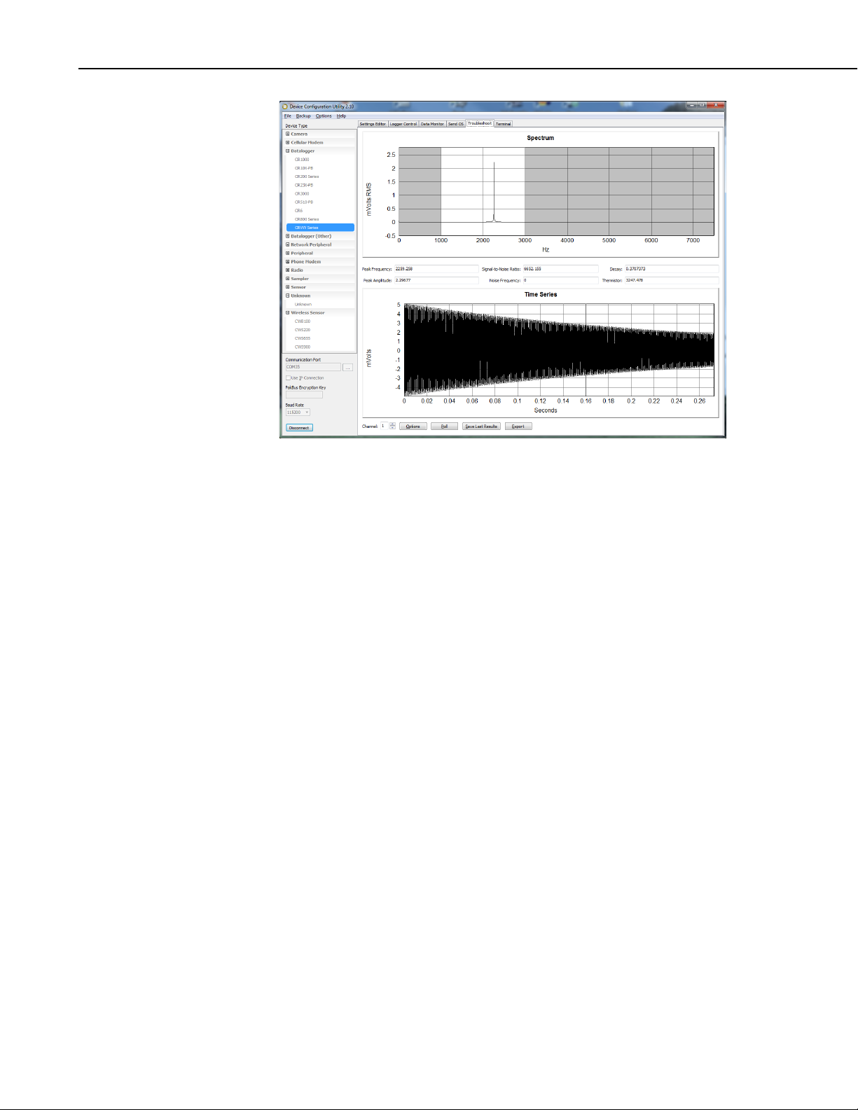
The Troubleshoot tab is provided so you can see detailed information about
the vibrating-wire sensor measurements made by the CRVW3. You can
manually trigger a measurement test and see diagnostic results within a few
seconds. Select your channel of interest in the Channel selection box. Use the
Options button to set the sweep excitation and frequency filtering window, and
also to set the excitation voltage level to be used during the test. Press the Poll
button to initiate the test. Within a few seconds the results will be displayed on
the screen.
The Spectrum window shows the frequency domain response of the vibratingwire sensor. Peaks in the spectrum indicate the main frequencies at which the
sensor’s wire vibrated during the measurement. The strength of the peaks are
shown in the millivolt scale. Drag a rectangle on the viewing area to zoom in.
Press the Undo Zoom button to return to the initial scale.
The Time Series window shows the motion of the sensor’s wire (in millivolts)
during the measurement period as given by the changing magnetic field sensed
by the coil circuitry. Drag a rectangle on the viewing area to zoom in. Press
the Undo Zoom button to return to the initial scale.
The main frequency reading is given in the Peak Frequency box in units of
Hertz (Hz). Other diagnostic readings are given to help assess the quality of
the reading:
• Signal-to-Noise Ratio: The amplitude (mV) of the strongest
frequency peak in the spectrum divided by the amplitude (mV) of the
nd
strongest frequency peak.
2
• Decay (Decay Ratio): The amplitude (mV) of the time-series motion
of the wire at the beginning of the measurement divided by the
amplitude (mV) of the wire motion at the end of the measurement.
This can also be approximately discerned by a study of the results in
the Time Series window.
• Peak Amplitude: The amplitude in millivolts (mV) of the strongest
frequency peak in the spectrum.
nd
• Noise Frequency: The frequency (Hz) of the 2
strongest frequency
peak in the spectrum.
• Thermistor: The measurement of the thermistor’s electrical resistance
in units of Ohms.
23
Page 34
CRVW3 3-Channel Vibrating-Wire Datalogger
Use the Save Last Results button to save the results of the test to a binary file
(*.bin). This file can be sent to Campbell Scientific support personnel (or to
others) and then opened within DevConfig using the Offline Analysis tab that
is shown when not connected to the CRVW3. This will allow others to assess
the condition of your sensor measurement in detail. Use the Export button to
save the results of the test into a text file that is readable using standard text
editor programs.
The Send OS tab is used when updated firmware (an operating system) is
installed into the CRVW3. Campbell Scientific will periodically provide
firmware updates for the CRVW3 on its website. (see
www.campbellsci.com/downloads). Once a newer firmware file is obtained
from the website, follow the installation instructions that are displayed when
this tab is selected.
You can use the Terminal tab to make a terminal mode connection to the
CRVW3. This is typically used under the direction of Campbell Scientific
support personnel or by advanced users. See Appendix B, Terminal Mode
from Connect Screen or DevConfig, for more information.
8.1.7 Validating Radio Connectivity in the Lab
For CRVW3 devices with the –RF451 or –RF407 communications option, you
should verify while still in the lab that the radio is working and has been
configured to be reasonably ready for field operation.
When using CRVW3-RF451 devices, the simplest way to confirm this is to use
an RF450 radio (www.campbellsci.com/rf450) connected to your lab computer.
The RF450 operates as the master radio device and the base station. The
CRVW3-RF451 device is configured as a slave device. (See Section 10.2.6,
Planning RF451 Radio Networks, for more details about master/slave radio
configurations and base station considerations.)
24
Page 35

The RF450 and CRVW3-RF451 can usually communicate easily in lab
NOTE
conditions, if they are within about 100 feet of each other, and if the RF450 is
using a small 1/2 wave antenna (pn 19512). When the RF450 uses an antenna,
then usually no antenna is required on the CRVW3-RF451 (while in the lab).
You can use the Device Configuration Utility (DevConfig) to test radio
connectivity. For details about using LoggerNet to test the radio connectivity,
see Section 10.7, LoggerNet Configuration.
If you are testing the radio connectivity of multiple CRVW3RF451 devices, only one of those devices at a time should be
powered up and tested when using this test method.
8.1.7.1 Configuring the RF450 Radio
Power the RF450 using an adapter with the DC POWER connection, or use a
CS I/O connection to a datalogger or A100/PS100 using an SC12 or other
serial cable. Connect the RS-232 port of the RF450 to the serial COM port on
your DevConfig computer. Select RF450 for the device in the radio section of
DevConfig. Just before you press Connect in DevConfig, physically press the
SETUP button on the side of the RF450. The CTS and CD LEDS should turn
green.
CRVW3 3-Channel Vibrating-Wire Datalogger
Set these settings with DevConfig:
• Active Interface : RS-232
• Baud Rate : 115.2K
• Radio Operation Mode: Multi-Point Master
• Repeaters Used : leave unchecked
• Network ID : This value should match the CRVW3 ID exactly ( 0 to
4095)
• Frequency Key : Leave at 5
• Transmit Power : Leave at 10
• Receive SubNet ID: Leave at 15
• Transmit SubNet ID : Leave at 15
• Radio ID: This must be unique for each radio device: Use “1”
(CRVW3 will use 0)
Press Apply. Leave the RF450 powered during the test. Leave the serial COM
port cable on the RS-232 port of the RF450 connected to the computer.
8.1.7.2 Configuring the CRVW3-RF451
Provide power to the CRVW3 per Section 8.1.3, Providing Temporary Power
to the CRVW3. Connect the USB cable between the CRVW3 and the
computer. In DevConfig, choose CRVW Series, select the port that was created
when the USB driver was activated, and press Connect. In the Settings Editor
tab, choose the Radio sub-tab.
Set the following settings:
• Radio Enabled : True
• Radio Operation Mode : Point to MultiPoint Slave
• Frequency Key : 5 (matches RF450)
• RF Transmit Power : Leave at 10
25
Page 36

CRVW3 3-Channel Vibrating-Wire Datalogger
NOTE
NOTE
• Low Power Mode : Leave at 2
• Repeater Frequency : Leave at “Use Master Frequency Key”
• Receive SubNet ID : 15 (matches RF450)
• Transmit SubNet ID : 15 (matches RF450)
• Network ID : Same value as given for RF450 – must match (0 to
4095)
• Radio ID: Leave at zero (must be unique/different from RF450 radio
ID, which should be 1).
Press Apply. Disconnect the USB cable from the CRVW3.
When testing deployed devices in the field, you may have already
assigned different Radio ID, Network ID, and Frequency Key
values than those shown above. Make sure the Network ID and
Frequency Key values match between both (all) devices and that
the Radio ID is unique for each device.
8.1.7.3 Using DevConfig to Connect to the CRVW3-RF451 Over the Radio
Position the RF450 and computer to be at least 25 feet away from the CRVW3.
The CRVW3 should no longer be wired to any device. Highlight CRVW Series
in DevConfig (not RF450). Choose the port on the computer that is connected
to the RF450 radio. Now Press Connect. Confirm red and green flashes on the
RX/TX LED of the CRVW3 and on the RF450 as radio communications now
occur.
If no other CRVW3-RF451 devices are on the radio network (i.e., powered or
in range), then DevConfig connects only to the CRVW3 device that is powered
and available, using the RF450/COM port on the computer as a transparent
link. The DevConfig screens should act just as they do when the computer has
a wired connection to the CRVW3. You should be able to view and set all the
settings of the CRVW3 over the radio connection. Confirm that the Serial
Number and Station Name in the Main tab are correct and correspond to the
CRVW3 station being tested. Use the Data Monitor tab to confirm proper
CRVW3 operation.
If multiple CRVW3 devices need to be powered and located
within radio range of the RF450 base station computer, then you
must use LoggerNet to test their radio connectivity. LoggerNet
can distinguish between CRVW3 devices based on PakBus
address. Each CRVW3 should have a unique Radio ID setting
and a unique PakBus address. Follow the steps outlined in Section
10.7, LoggerNet Configuration, to perform multiple CRVW3
radio testing using LoggerNet.
8.2 Field Deployment of the CRVW3
When a CRVW3 is deployed to its permanent location in the field, there are
several key considerations which help to ensure that it works properly. This
section discusses how to get each device individually installed at its planned
location.
26
Page 37

CRVW3 3-Channel Vibrating-Wire Datalogger
NOTE
When using a CRVW3 with a radio option (–RF451 or –RF407),
it is recommend that you design the radio network before
deploying any device to the field. Radio connectivity is a factor
that can impact the geographic location of a CRVW3 site. See
Section
Radio Networks, for more information about the use of radios. It
is also recommended that at least some of the configuration of the
CRVW3 be done in the office or lab (Section 8.1
and Configuration) before deploying it into the field.
Bring a laptop with DevConfig installed when you travel to the installation site
(see Section 8.1.1, Preparing the Windows Computer (PC), and Section 8.1.4,
Connecting to the CRVW3). Consider the following tasks when installing a
CRVW3 station:
9, Radio Networks, and Section 10, Complex (Large)
, Lab Connection
• Connecting Sensors to the CRVW3
• Providing Power to the CRVW3
• Monitoring and Controlling Humidity Within the CRVW3 Enclosure
• Mounting the CRVW3 Enclosure
• Installing the CRVW3 Antenna (for devices with a radio option)
• Connecting the CRVW3 Electrical System to Earth Ground, Surge
Protection
• Validating and Fine-Tuning CRVW3 Settings
• Confirming CRVW3 Sensor Measurement Operation
• Validating Radio communications (when applicable)
• Sealing the CRVW3 Enclosure
Details about these tasks are provided in this section.
When installing devices with a radio option, bring a radio device into the field
that can operate as a radio base station. For the CRVW3-RF451 this is the
RF450 device configured as the master radio and LoggerNet software running
on a laptop computer.
8.2.1 Connecting Sensors to the CRVW3
Selection of the proper vibrating-wire sensors to meet your data acquisition
needs is a process that is beyond the scope of this document. Contact an
application engineer at your local Campbell Scientific support office for
guidance regarding sensor selection and purchase. Campbell Scientific, Inc.
also provides training related to the measurement of several kinds of vibratingwire sensors.
The vibrating-wire sensors to be measured should be located within a
reasonable distance of the CRVW3. Install the sensors according to
manufacturer supplied instructions. A 5-wire or 3-wire cable will connect
between each sensor and the CRVW3. Longer cable distances (more than
500 m or 1500 feet) may require the use of 12 volt excitation instead of 5 volt
excitation (see Excitation Voltage in Section 8.1.5, Configuring the CRVW3).
Since 12 volt excitation uses more power, consider how that excitation level
may impact your power storage. Vibrating-wire sensor connections can
provide reliable readings using cable distances up to 1500 m/5000 feet in some
circumstances. Cable distances less than 500 m/1500 ft. are recommended.
Up to three vibrating-wire sensors can be connected to each CRVW3.
27
Page 38

CRVW3 3-Channel Vibrating-Wire Datalogger
Vibrating-wire sensors containing a built in thermistor will have five wire
leads. Sensors that do not contain a built-in thermistor will have three leads. A
sensor with five wire leads will have two leads for the coil circuit, two leads for
the thermistor, and a shield lead. A 3-wire sensor has two leads for the coil
circuit and a shield lead.
Color coding of wire leads for some of the more prevalent vibrating-wire
sensors is shown in FIGURE 8-5.
FIGURE 8-5. Typical Vibrating-Wire Sensor Lead Colors and
Connections
Scheme 1: Red-coil-VW, Black-coil-VW, Clear-shield-ground, Greenthermistor-T, White-thermistor-T
Scheme 2: Orange-coil-VW, Orange-White-coil-VW, Clear-shield-ground,
Blue-thermistor-T, Blue-White-thermistor-T
Determine which channel on the CRVW3 will be used for each sensor.
Unscrew and remove the gland connector on the outside of the enclosure that
corresponds to the channel currently being installed. Remove the gland
capping pin, and then feed the removed gland connector over the bare leads on
the end of the sensor cable and position it a few inches down the cable. Now
feed the cable through the gland hole. Before securing the gland, first connect
the leads to the proper terminals on the CRVW3.
28
FIGURE 8-6. CRVW3 Cable Connection and Entry Points
Page 39

CRVW3 3-Channel Vibrating-Wire Datalogger
Connect the two leads of the coil circuit to the two VW terminals on the face of
the CRVW3 inside the enclosure. Choose the terminals that correspond to the
desired channel (1, 2, or 3). Since the polarity of the coil circuit for sensor
excitation and read-back makes no difference in the final measurement result, it
doesn’t matter which coil wire is connected to which VW terminal. If the
sensor has a thermistor, then connect the two thermistor leads to the T and T
terminals. Similarly, it doesn’t matter which thermistor lead is wired to which
T terminal. Connect the shield wire to the ground connector.
FIGURE 8-7. Wiring Panel of the CRVW3
After performing some of the validation steps shown later in this section, you
will become confident that the sensor is being measured properly by the
CRVW3. Once that occurs, you can then secure the gland into its permanent
field state. To do this, leave a slight amount of slack in the cable between the
terminals and the gland and then re-connect the gland cap (which was
previously threaded onto the cable) on the outside of the enclosure and tighten
it by hand or with a wrench. Ensure that the seal of the gland contacts the
cable evenly around its circular connection to avoid any water ingress. Pull
gently on the cable to ensure that it does not slide or move through the gland.
Repeat the sensor connection process for up to two additional sensors, using
the terminals provided for those channels. After the device is powered
(Section 8.2.2, Providing Power to the CRVW3), then tests can be performed to
validate that the CRVW3 is measuring the frequency and thermistor of the
connected vibrating-wire sensor properly (Section 8.2.8, Confirming CRVW3
Sensor Measurement Operation).
8.2.2 Providing Power to the CRVW3
Consider carefully how power will be provided to your CRVW3 station to
ensure reliable field operation.
If there is no electrical distribution grid power available at your CRVW3 site,
then you must use a battery option to provide power to the device. Two main
battery options are available: –ALK and –RC.
8.2.2.1 Alkaline D-Cell Option (–ALK)
If you selected the –ALK option when ordering your CRVW3, then it uses
alkaline D-cell batteries for power. Eight cells are installed into the provided
battery pack. When using this option, no solar panel or charge mechanism is
required. However, visits to the site will be required on a regular basis to
remove old batteries and insert new ones. The length of time that the CRVW3
29
Page 40
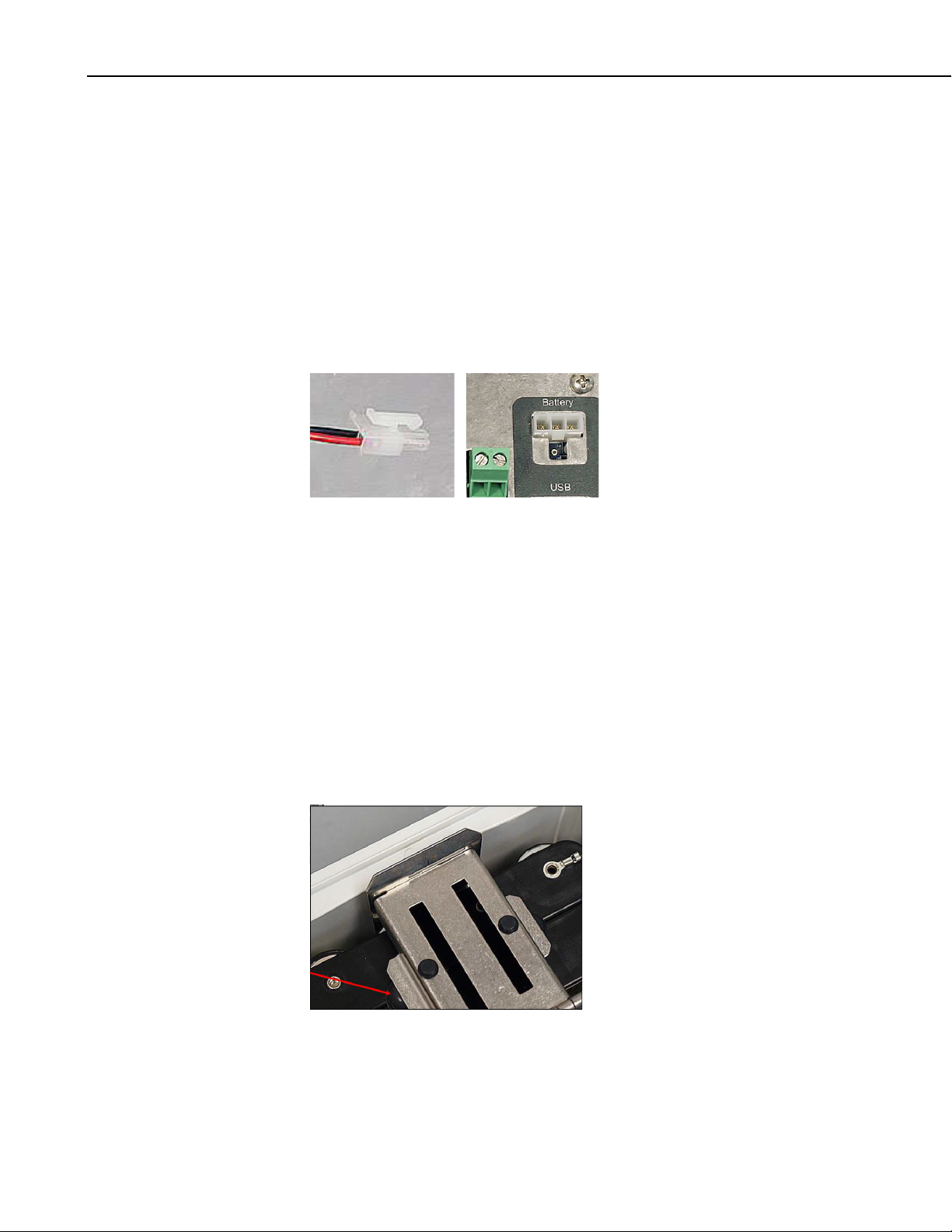
CRVW3 3-Channel Vibrating-Wire Datalogger
can operate with one set of eight batteries depends on a number of factors.
These factors include which radio option is used (the –RF451 option requires
more power than the –RF407 option), how often measurements are made, how
often radio contact is made with other devices, and whether the site experiences
cold temperatures or extreme changes in temperature. Alkaline battery
discharge periods from several months up to one year are anticipated. Spend
some time observing the CRVW3 in operation to formulate and refine the
optimal battery maintenance schedule for your stations.
The –ALK battery pack should have arrived from the factory with the D-cell
batteries already installed and the battery pack secured inside the enclosure. To
power-up the CRVW3 using this pack, connect the battery connector to the
CRVW3 panel as shown here:
FIGURE 8-8. –ALK Battery Pack Connector Cable and CRVW3 Battery
Connection
LED activity should immediately occur on the CRVW3 indicating startup and
operation. If no LED activity is observed, the batteries may be discharged and
should be checked and replaced if necessary.
When changing out the batteries, disconnect the power connector, and then
remove the battery pack from the CRVW3 by disengaging the securing latch
(push on the metal backing for the hinge to snap out). Once the battery pack is
removed from the enclosure, you can remove the old D-cells, and insert the
new D-cells. The battery pack can then be placed back into the CRVW3
enclosure and the latch secured. Ensure that the bumpers on the pack contact
the latch and that the battery pack does not wiggle when pressed.
30
FIGURE 8-9. Bumpers Used to Secure the -ALK Battery Pack
Page 41

8.2.2.2 Rechargeable Battery Option (–RC)
NOTE
NOTE
If you selected the –RC option when ordering your CRVW3, then a 7 Ahr
rechargeable battery is used to power the device. You will need a solar panel
or some other DC voltage source (16 V to 28 V) to recharge the battery. Due
to the power requirements of the –RF451 radio option, it is anticipated that
most deployments of the CRVW3-RF451 will use the –RC option.
Although it is possible to operate the CRVW3 from a fully charged
7 Ah rechargeable battery without using a charge mechanism or
solar panel, it is anticipated that longer discharge times will be
obtained from the –ALK option rather than the –RC Option. The
–ALK option is recommended for non-charging battery-only
power scenarios.
The CRVW3 includes a built-in charge regulator to simplify the deployment
and use of a solar panel. The output from the solar panel connects directly into
this regulator via the charge terminals of the CRVW3.
The charge regulator can sense the voltage provided by the solar panel and
decide whether to charge the battery or simply draw power from the battery.
This ensures constant device operation during changes between periods of full
panel power production to periods of little or no panel output. This includes
changes from day to night or changes from clear weather to heavy cloud cover.
When sufficient power has been provided to charge the battery to its full state,
the charge regulator also applies just enough power to keep the battery in the
fully-charged state.
CRVW3 3-Channel Vibrating-Wire Datalogger
A 10 watt solar panel (SP10) is commonly used with the CRVW3. However,
5 watt or 20 watt panels (SP5, SP20) may also be used depending on sitespecific power needs. Procure the hardware needed to mount the panel for
optimal output. Installation instructions are provided with that hardware. The
solar panel should be installed with the visibility and orientation that optimizes
the capture of solar energy.
A spreadsheet is available from Campbell Scientific to help you
determine which solar panel you should use based on the
frequency of your measurements, radio communication activity,
and estimated solar exposure. Contact your local support office
for more information.
When connecting the solar panel output cable to the CRVW3, feed the cable
through the corresponding gland and secure the gland seal using a similar
process to that described in Section 8.2.1, Connecting Sensors to the CRVW3.
Connect the solar panel cable to the Charge “+” and “–” terminals. The
polarity of the leads from the solar panel must be observed, so check the
cabling carefully.
31
Page 42

CRVW3 3-Channel Vibrating-Wire Datalogger
NOTE
FIGURE 8-10. Power Source Connection to the CRVW3 Charge
Terminals
Connect the 7 Ah rechargeable battery into the power/charge circuit by
plugging the provided connector into the “Battery” connector on the panel.
8.2.2.3 Grid Power
FIGURE 8-11. –RC Battery Connector Cable and CRVW3 Battery
Connection
When either a charged battery is connected to the CRVW3 or sufficient voltage
is applied to the charge terminals of the CRVW3, then LED activity should be
observed on the device to indicate startup and operation.
It is possible to convert a CRVW3 device from the –RC option to
the –ALK option and vice versa. This involves obtaining the
desired battery or battery pack from Campbell Scientific, and then
reversing the latch that secures the battery within the enclosure.
This is done by removing the battery hinge pin, rotating the hinge
bracket to accommodate the desired battery option, and then reinserting the hinge pin. Contact your local support representative
if further details about this process are required.
If grid power is available at the CRVW3 site, then that can be used as the main
power source. Although the CRVW3 can operate exclusively from a proper
voltage applied to its charge terminals, a battery option is still recommended
for backup purposes and measurement continuity in case of power outages.
Use pn 29796 as the main power source and connect it through the appropriate
gland to the charge terminals. Any charge source with a level of 16 V to 28 V
may be used. A rechargeable battery is recommended (–RC option) as a
backup source in this scenario. When the device is powered by applying
voltage to the charge terminals, the battery will be charged (or kept fully
32
Page 43

charged) during those times when grid power is available. It is also possible to
use the –ALK option for backup power. In that case, the D-cell alkaline
battery pack will be drawn upon for power only when the voltage on the charge
terminals is low or zero. No charging of the batteries occurs with the –ALK
option.
8.2.3 Humidity Monitoring and Control
To ensure proper operation of the CRVW3, steps can be taken to control
moisture and humidity conditions inside of the enclosure. Approximate
humidity history can be tracked for analysis during maintenance visits to the
site.
Install the humidity indicator card (pn 28878 included with CRVW3 shipment)
by attaching it using the included backing tape. Place it on the inside of the
enclosure lid above the desiccant holder. Review the status of the indicator
card when maintenance visits are made to the CRVW3 site.
Ensure a fresh desiccant package (pn 4905 included with CRVW3 shipment) is
inserted into the desiccant holder. Note that the Quick Deploy Guide is also
kept in the desiccant holder. Additional desiccant packs can be ordered from
Campbell Scientific when needed.
CRVW3 3-Channel Vibrating-Wire Datalogger
Humidity conditions can vary widely among CRVW3 deployment locations
and associated weather conditions. Monitor the state of the humidity indicator
card in order to determine when a replacement desiccant pack is needed.
Humidity history from a weather station near the CRVW3 may also be helpful
in predicting desiccant maintenance schedules.
8.2.4 Mounting the CRVW3 Enclosure
The enclosure of the CRVW3 can be securely attached to a pole or other
applicable mounting hardware. Use the supplied mounting kit (option –SM,
included with CRVW3 shipment) or the Universal Mounting Bracket (pn
30840, –UM option, shown in FIGURE 8-12) to secure the CRVW3 enclosure
at its permanent location.
FIGURE 8-12. CRVW3 with the –UM mounting option
33
Page 44
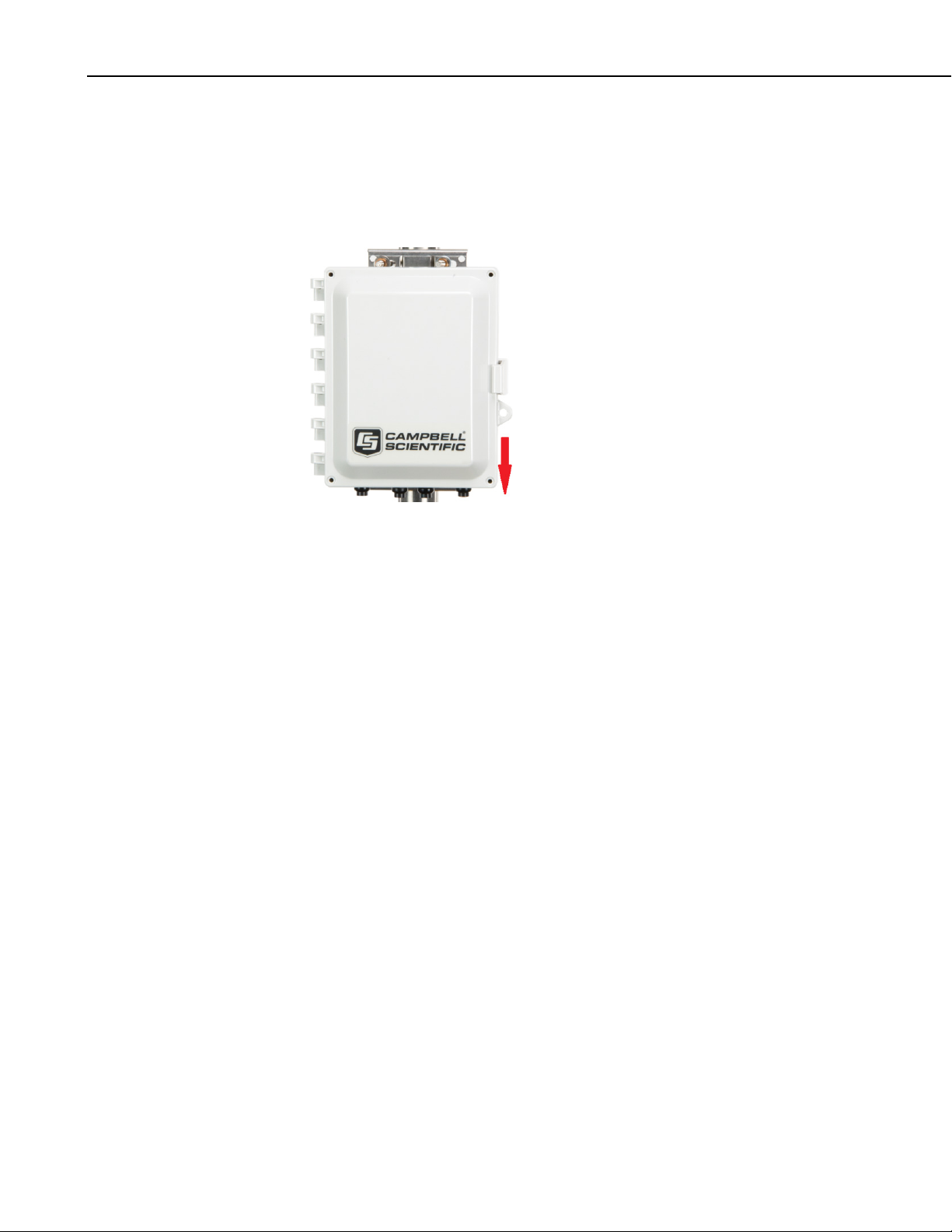
CRVW3 3-Channel Vibrating-Wire Datalogger
Also consider the location of the solar panel and antenna and how the cabling
of those two items will connect into the CRVW3 enclosure.
Mount the enclosure with the sensor glands, antenna connector, and ground lug
facing downward. This minimizes water exposure (rain, snow, etc.) to those
locations, and helps ensure that the inside of the enclosure remains dry.
FIGURE 8-13. Proper Field-Installed Orientation of the CRVW3
8.2.5 Installing the CRVW3 Antenna
When using a radio option on the CRVW3 (CRVW3-RF451 or CRVW3RF407), you should carefully consider the kind of antenna to use with the
device. You should ensure that it can communicate properly with the
applicable remote CRVW3 devices, radio repeater stations, and the radio base
station. (See Section 9, Radio Networks, and Section 10, Complex (Large
Radio Networks) for more information about the configuration of radio
networks).
A small “whip” or “dipole” antenna may be connected directly to the enclosure
bottom (pn 15731 for the –RF451 option). These are used for testing or for
short distance communication links. For longer distances, a higher gain,
externally cabled antenna is usually necessary. These antennae require
mounting hardware (a pole, etc.) separate from the CRVW3. Be sure to order
an antenna cable long enough to connect between the antenna mount and the
mounted location of the CRVW3.
If the CRVW3 communicates with only one other radio station or device, use a
directional antenna (such as a Yagi, pn 14201), and position the antenna so it
points directly at the remote station. If the CRVW3 communicates with more
than one radio station or device (i.e., when it is configured to operate as a
repeater station), then an omnidirectional antenna (aka “omni”) should be used
(pn 14221). Raising the antenna to a higher elevation may improve the signal
reception and transmission.
34
Antenna connections that are exposed to the environment should be protected
with self-vulcanizing tape (pn 21212). A surge suppressor kit (pn 31312) is
also recommended when using cabled antennas. This will protect against
lightning strikes or other electrical hazards. An example of weatherproofing
installed on a surge suppressor connection is shown in FIGURE 8-14.
Page 45
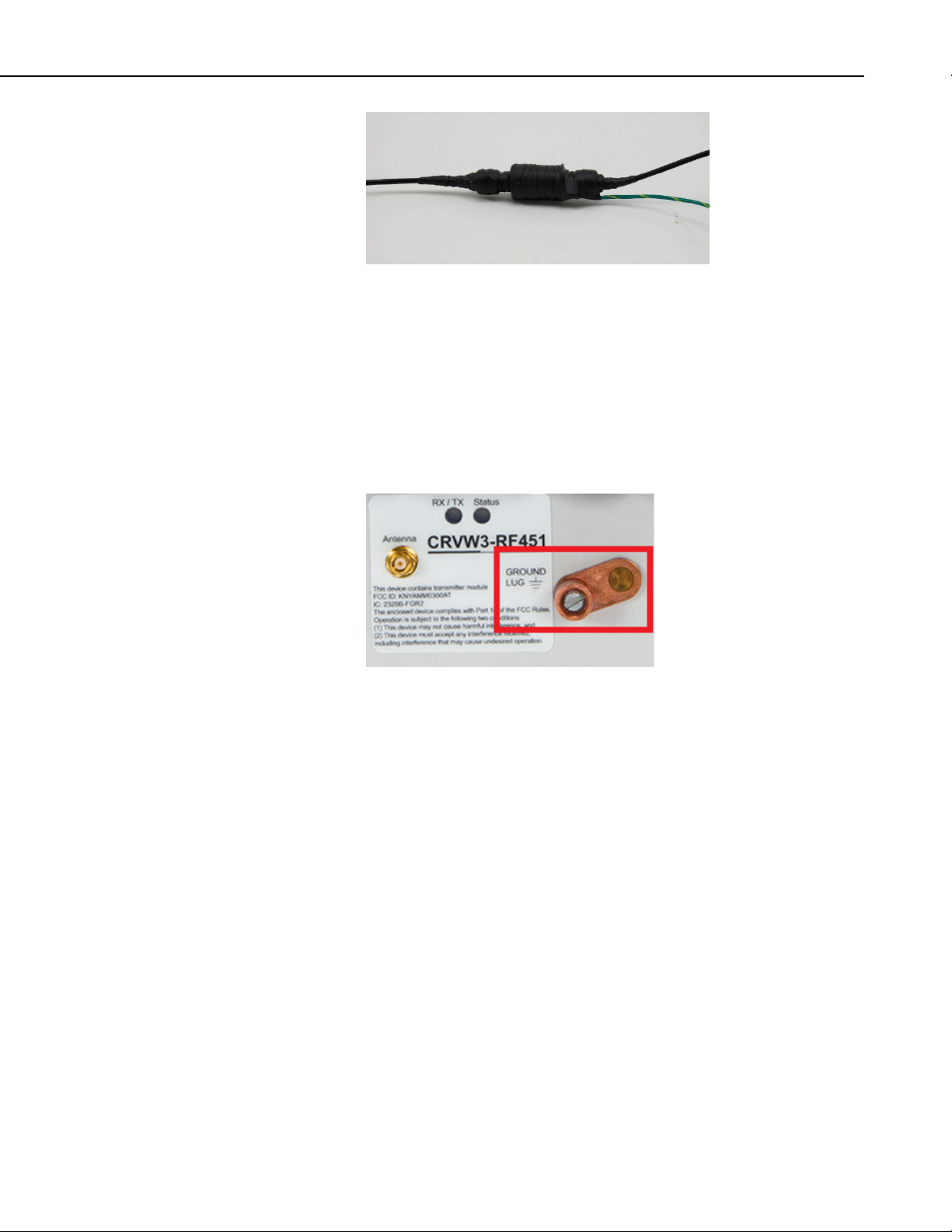
CRVW3 3-Channel Vibrating-Wire Datalogger
FIGURE 8-14. Properly Weather-proofed Antenna Cable Connection
with Surge Protection
8.2.6 Connecting the CRVW3 Electrical System to Earth Ground
Electrical grounding of the CRVW3 station helps protect your hardware
investment by mitigating against the risk of lightning strikes, static discharges,
or other unexpected electrical conditions. Connect the ground lug to an
adequate earth/soil connection using a low gage wire (8-12 AWG) that
accommodates high current flows.
FIGURE 8-15. CRVW3 Ground Lug Location
The Campbell Scientific small enclosure grounding kit (pn 31163) can be used
to make this connection.
8.2.7 Validating and Fine-Tuning CRVW3 Settings
Before completing the deployment of your CRVW3, you should confirm that it
is configured to operate in the way you expect. Plan to have a laptop or other
Windows computer running DevConfig with you in the field so you can
connect to and configure the device. Be sure to bring the USB cable (pn
27555) that was included in your CRVW3 shipment. Section 8.1.5,
Configuring the CRVW3, discusses the basic configuration of a CRVW3
device. If no configuration of the CRVW3 for the current sensors has been
previously performed, then first follow the steps outlined in that section to
configure the CRVW3.
The main measurement output from a vibrating-wire sensor is a frequency (in
units of Hz or Digits) that corresponds to the natural resonance vibrations of
the wire element embedded within the sensor. This frequency changes as the
phenomenon being measured changes. It is important that you consult the
manual of your vibrating-wire sensor to document the highest and lowest
frequencies that are expected as output. Consider the most extreme conditions
35
Page 46

CRVW3 3-Channel Vibrating-Wire Datalogger
NOTE
of the phenomenon you are measuring. Then consider the highest and lowest
frequency that can be expected under both of those conditions. Using this
information, you will formulate both a low frequency value and high frequency
value that is configured into the CRVW3. This frequency range is used during
excitation and also during the read-back of the sensor. When exciting the
sensor, only energies within the specified frequency range are used for
excitation. When reading out the sensor’s response, only frequencies within
the window are processed, and frequencies outside the specified range are
ignored. This is one of the ways that the VSPECT technology filters unwanted
noise out of your vibrating-wire measurements.
Using DevConfig, make sure the following settings are properly configured:
• Station Name
• Measurement interval
• PakBus Address
• IsRouter (should be set to “true” when the CRVW3 is also a radio
repeater device).
Then make sure that the following settings are properly set for each sensor
channel:
• Channel Enabled
• Channel Name
• Excitation Voltage
• Begin Frequency, End Frequency
• Thermistor Enabled
• Calculate Engineering Output
Refer to Section 8.1.5, Configuring the CRVW3, for more details about
configuring and applying these settings. Consider saving the XML (*.xml)
configuration file on your laptop to store the settings as they were applied to
your device in the field.
When using the –RF451 radio option, there are some key settings
on the Radio and Radio Advanced tabs of DevConfig that should
be confirmed. See Section
in the Lab, and Section 8.2.9
Operation.
8.1.7, Validating Radio Connectivity
, Validating CRVW3 Radio
8.2.8 Confirming CRVW3 Sensor Measurement Operation
Once the CRVW3 is properly installed at its permanent deployment site and
configured for operation, you should confirm (before leaving the site) that it is
measuring its sensors properly. This validation includes the use of a laptop
running DevConfig connected via USB cable.
36
8.2.8.1 LED Operation
You can observe the LED behavior of the CRVW3 to assess its condition. The
LED lights can be observed from both the inside and the outside of the
enclosure.
Page 47

CRVW3 3-Channel Vibrating-Wire Datalogger
TABLE 8-1. CRVW3 LED Behavior
FIGURE 8-16. LED Viewing Locations on the CRVW3
TABLE 8-1 summarizes LED operation on the CRVW3.
RX/TX LED (left side) Status LED (right side)
Solid Red
Solid Orange
Blinking Red
Blinking Green
Off
Radio Error
Configuration of Radio, Busy,
No communications will
occur
Radio Transmit (TX)
Radio Receive (RX)
No Radio Activity
When the CRVW3 is powered up or has a change of settings applied, it
executes its startup sequence. During the final stage of the startup sequence,
you will see both LEDs in a solid orange state. Allow time for the startup
sequence to complete (up to 20 seconds) before attempting to connect to the
CRVW3. Once the startup sequence is finished, the two LEDs will stop
showing solid orange, and begin to indicate the regular measurement and
communications status of the device.
Solid Red
Solid Green
Solid Orange
Blinking Red
Blinking Green
Blinking Orange
Off
Measurement or Program Error
Measuring Sensor(s)
Configuration of Device
Settings or OS, Busy, No
communications will occur
No measurements possible with
only USB power
Awake (heartbeat)
Awake (heartbeat) - in Repeater
mode for –RF451 option
Device asleep or powered down
When the CRVW3 begins operating you will see a green flash on the Status
LED every few seconds to indicate that the device is awake. If the CRVW3RF451 is configured as a radio repeater (see Section 10.1, Radio Network
Station Types), then the Status LED will flash orange instead of green while it
is awake. While the device is measuring its sensors, the Status LED will show
as solid green. This lasts about 1-3 seconds and then the solid green condition
ends. You should observe this LED behavior to confirm that the CRVW3 is
measuring its channels at the desired interval (which was set previously using
DevConfig).
37
Page 48

CRVW3 3-Channel Vibrating-Wire Datalogger
As a power-saving feature, the CRVW3 remains awake between measurements
only for a limited time. If the device is powered up without a USB cable
connected to it, it will remain awake between measurements (indicated by the
green or orange “awake” flash on the Status LED) for five minutes. After five
minutes, the device will sleep between measurements. While in sleep mode,
the CRVW3 will wake up only long enough to measure its sensors and store
the results, and the Status LED will light up as solid green during that time.
The device then immediately returns to sleep, and therefore no “awake”
indicator flashes (green or orange) will be observed between measurements.
The CRVW3 will wake up (if not already awake) and remain awake as long as
the USB cable is connected to the device. After the USB cable has been
disconnected, the device will remain awake for five minutes, and then sleep
between measurements.
On devices with the –RF451 and –RF407 options, the RX/TX LED flashes red
when transmitting data over the radio and green when receiving data over the
radio. A solid red condition indicates a radio error.
Radio transmissions received by the device will wake it up if needed. The
device will remain awake for as long as radio activity is in process plus an
additional 10 seconds (just in case additional radio transmissions are received).
After that the device will return to sleep (if it was asleep before the radio
transmissions were first received).
8.2.8.2 Validation with DevConfig
To perform measurement validation with the laptop, connect the USB cable,
run DevConfig, and connect to the CRVW3 (see Section 8.1.4, Connecting to
the CRVW3, for more information). The top set of tabs displayed after
connecting includes the Troubleshoot tab. Use the Troubleshoot tab screen
to test and examine the sensor response for each channel. The diagnostic
information provided helps you determine whether the connected sensor is
operating correctly and is providing proper measurement readings. Press the
Poll button to perform the test and wait a few seconds for the results to appear
on the screen. Use the Channel selection box to select each active channel in
turn for individual testing.
A high-quality sensor response (spectrum and time-series waveform in the
Troubleshoot screen) is shown here:
38
Page 49
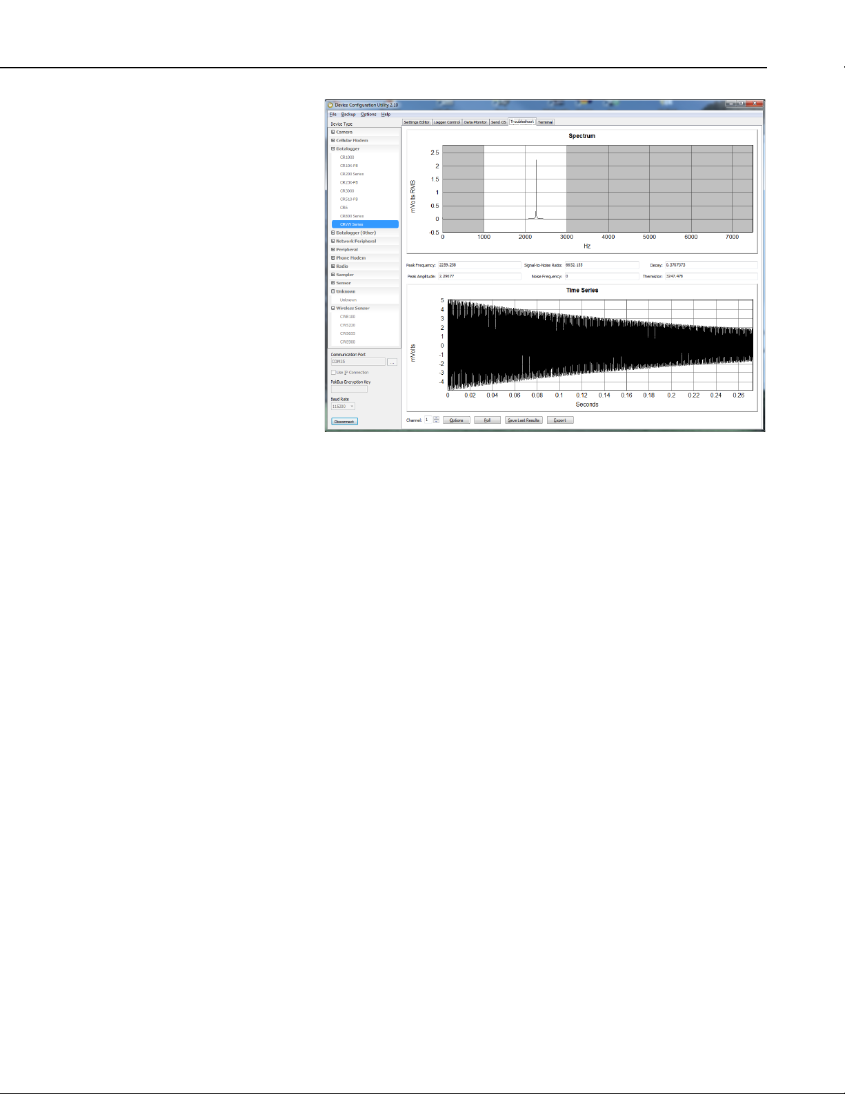
CRVW3 3-Channel Vibrating-Wire Datalogger
Check the Peak Frequency to ensure that the main sensor reading is in the
expected range. A Signal-to-Noise Ratio of 6 or greater is preferred. Check
the Thermistor value (in units of Ohms) if used.
If multiple peaks occur in the response spectrum of the sensor, be sure to
choose the Begin Frequency and End Frequency carefully to eliminate
unwanted signals, yet still allow for variation of the sensor output frequency
due to changes in the measured phenomenon. The grey shading in the
Spectrum display indicates how the beginning and ending frequencies are set.
Use the Options button to temporarily experiment with different frequency
window ranges. Use the Channel1, Channel2, and Channel3 tabs (under the
Settings Editor tab) to make permanent changes to the Begin Frequency and
End Frequency settings.
You can use the Save Last Results or Export buttons to save the test
information shown on the screen into a file. These saved results can be stored
and used as a historical reference (baseline or datum point) for comparison
with the same sensor’s behavior in the future. The saved results can also be
sent to others (including Campbell Scientific support personnel) for evaluation
and troubleshooting purposes. Use the Off Line Analysis tab of DevConfig
(shown when disconnected from the CRVW3) to open and view a file saved
previously with the Save Last Results button. Refer to Section 8.1.6, Testing
the Measurement Operation of the CRVW3, for more information about the
operation of the Troubleshoot tab screen.
Use the Data Monitor tab in DevConfig to view frequency and temperature
data in both the Public table and the VW_Data table. The VW_Data table is the
final storage table used to persist measurements made by the CRVW3. You
should confirm that the data in the VW_Data table is updating immediately
after each measurement is made by the device. Refer to Section 8.1.6, Testing
the Measurement Operation of the CRVW3, for more information about using
the Data Monitor tab.
39
Page 50

CRVW3 3-Channel Vibrating-Wire Datalogger
8.2.9 Validating CRVW3 Radio Operation
If you have a CRVW3 with a radio option (–RF451 or –RF407), then you
should validate that the radio on the device is working properly before leaving
the site. Use a laptop computer running DevConfig and LoggerNet with a USB
connection to do this. Follow the process described in Section 8.1.7,
Validating Radio Connectivity in the Lab, using the antenna just installed for
the CRVW3, and a “whip” antenna on the portable base radio.
For devices with the –RF451 option, you will use a mobile RF450 device
configured as the master radio and connected to the laptop. Position the laptop
and master radio at least 25 feet away from the antenna installed on the
CRVW3 to avoid radio frequency (RF) interference that can impede
communications.
8.2.10 Sealing the CRVW3 Enclosure
Once you have completed the installation of the CRVW3 and confirmed proper
measurement and communication functionality, you should seal the enclosure.
This will ensure optimal protection and maximize operational up-time. Proper
enclosure sealing helps to avoid unwanted entry of water or humid air, and
provides isolation from other environmental factors.
Ensure that the enclosure is mounted so as to minimize water exposure to the
sensor glands, antenna connector, and ground lug (typically these items should
face downward).
Ensure that the cable entry points are installed and tightened properly. Ensure
that the humidity monitoring card and desiccant are in place (Section 8.2.3,
Humidity Monitoring and Control). The CRVW3 enclosure includes a small
vent to allow for changes in pressure. A gore patch prevents water from
entering the enclosure through the vent.
Ensure than nothing impedes the lid from closing properly (USB cable
removed, RF diagnostic cable removed), then close the lid of the enclosure and
secure the latch. A padlock can be used to protect the closed lid from
unauthorized access, if desired.
40
Page 51
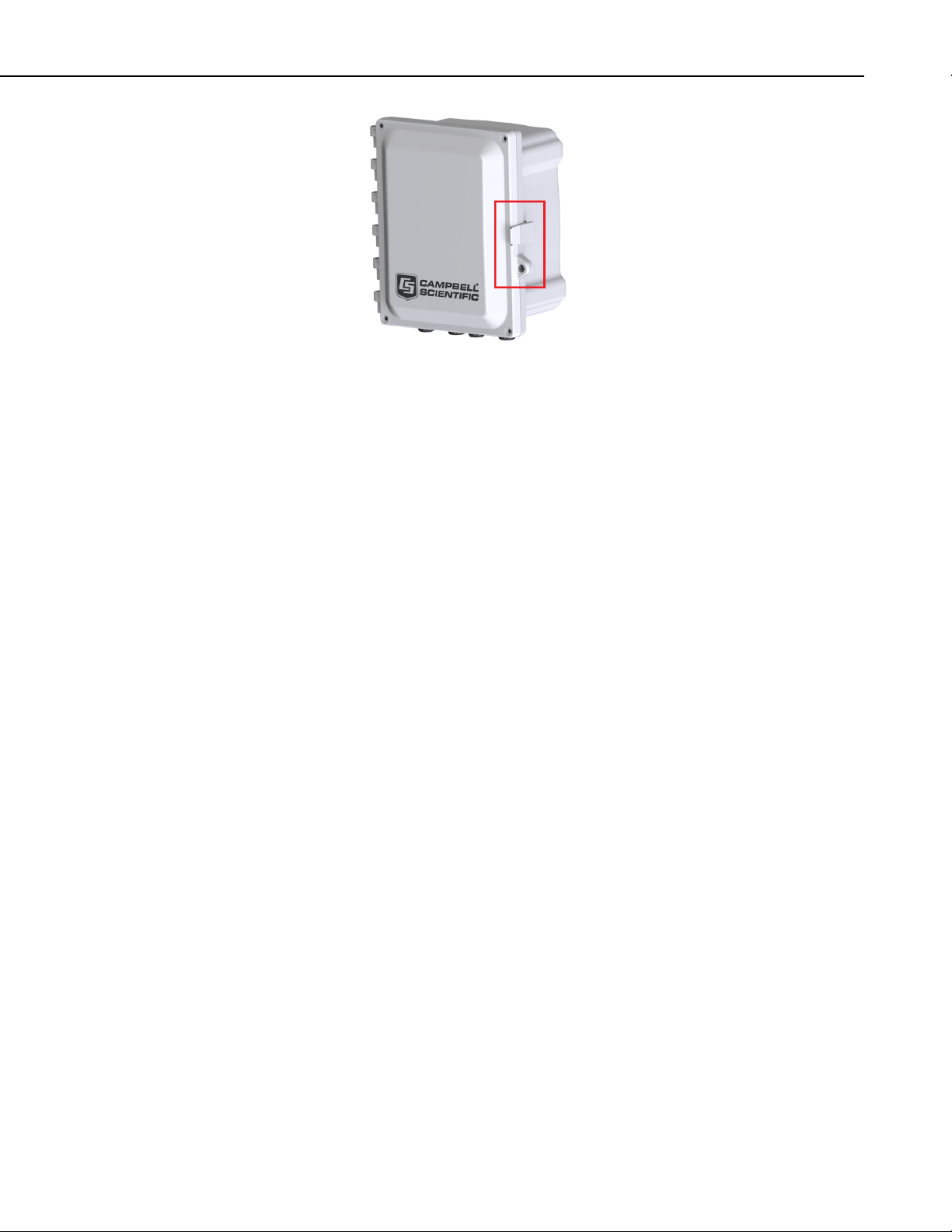
CRVW3 3-Channel Vibrating-Wire Datalogger
FIGURE 8-17. CRVW3 Latch Closure and Lock Location
Screws are provided by the enclosure manufacturer to maximize water
protection. Install these screws into each of the four corners of the enclosure to
ensure the maximum protective seal between the lid and the main section of the
enclosure.
During maintenance, you should wipe off any water from the outside of the
enclosure before opening the enclosure lid.
8.3 On-site Manual Data Collection
A technician located at a deployment site can use a USB cable to manually
collect measured data from a CRVW3 using a Windows computer (laptop PC)
and LoggerNet, PC400, or PC200W software.
See Section 11.2.2, Manual Data Collection at the CRVW3 Site, for details
about this data collection process.
9. Radio Networks
Any deployment of radio-based CRVW3 devices involves the installation and
operation of a radio network. That radio network can be simple or complex,
depending on how it is designed and implemented. Implementation decisions
are driven by the measurement requirements and geographic constraints of the
desired data collection system.
When creating CRVW3 radio networks, a base radio station is always
required. The base station functions as a gateway device enabling non-radio
communications to enter or exit the radio network. The communications
pathway provided by the base radio is critical for LoggerNet or other software
or hardware to communicate with a network of CRVW3 devices.
41
Page 52

CRVW3 3-Channel Vibrating-Wire Datalogger
FIGURE 9-1. CRVW3 Radio Network
For many deployments, a simple radio network design will adequately satisfy
the system's requirements. Basic instructions are provided in this section to
facilitate timely field implementation and operation of simple networks. More
detailed guidance is provided in Section 10, Complex (Large) Radio Networks,
for planning and configuring networks with greater complexity.
9.1 Simple Radio Network Definition
To determine whether your needs can be met with a simple radio network,
consider the following requirements:
• The CRVW3 stations in the network should all have single-hop radio
links to the base station
o no repeater stations should be required
o a line-of-sight radio transmission path should exist between each
CRVW3 and the base station
o The distances between the base station and each CRVW3 should
be conservative for the radio option being used.
• The base station location should have TCP/IP or internet connectivity
sufficient to communicate with the Windows computer station that
runs the LoggerNet software.
42
Page 53

CRVW3 3-Channel Vibrating-Wire Datalogger
NOTE
• No measurements should be required to be made at the base station's
location
The term “single-hop” refers to a CRVW3 station’s ability to make a radio
connection directly with the base station without the need to route its radio
communications through another radio-enabled station (i.e., no repeating is
required). When fewer stations are used (10 or less) or shorter distances are
used, then the complexity of the network can be reduced significantly.
If Ethernet TCP/IP connectivity (wired) is available at the base
station location, a Campbell Scientific NL201 device is
recommended – pn 26245
Note that the TCP/IP requirement can be met in some cases by
using a cell phone modem such as the LS300G (pn 31099,
http://www.campbellsci.com/ls300g ). If WiFi connectivity is
available at the base station location, the NL240 device may be
used – pn 28714
section we provide instructions for using the NL201 device to
connect the base radio to a TCP/IP network.
If your system does not meet the above criteria, refer to Section 10, Complex
(Large) Radio Networks.
http://www.campbellsci.com/nl240 . In this
http://www.campbellsci.com/nl201 .
9.2 Simple Network Installation Overview
The high-level process for setting up a simple network includes:
• Deploying and Configuring individual CRVW3 measurement stations
• Enabling and confirming radio connectivity on each CRVW3 station
• Installing the base station and confirming radio connectivity between
it and the CRVW3 stations
• Using LoggerNet to connect to the base station and then to the
CRVW3 stations
• Setting up automatic collection within LoggerNet for each CRVW3
station
In the simplest network, you have one base station and one remote station. No
matter how many stations are in the network, there is always only one base
station. All remote stations will communicate with the same base station.
If a CRVW3 station cannot make a radio communications link directly with the
base station, then a radio repeater station must be inserted between those two
locations. The design and use of repeater stations is discussed in Section 10,
Complex (Large) Radio Networks. This section assumes that no repeater
stations will be required.
9.3 CRVW3-RF451 Simple Network Installation
In a simple network installation for CRVW3-RF451 devices, the RF450
radio+modem device (pn 18326, www.campbellsci.com/rf450) will be used as
the main component of the base station. The RF450 is configured as the
master radio. Please refer to the RF450 manual for more information about the
use of the RF450: s.campbellsci.com/documents/us/manuals/rf450.pdf.
43
Page 54
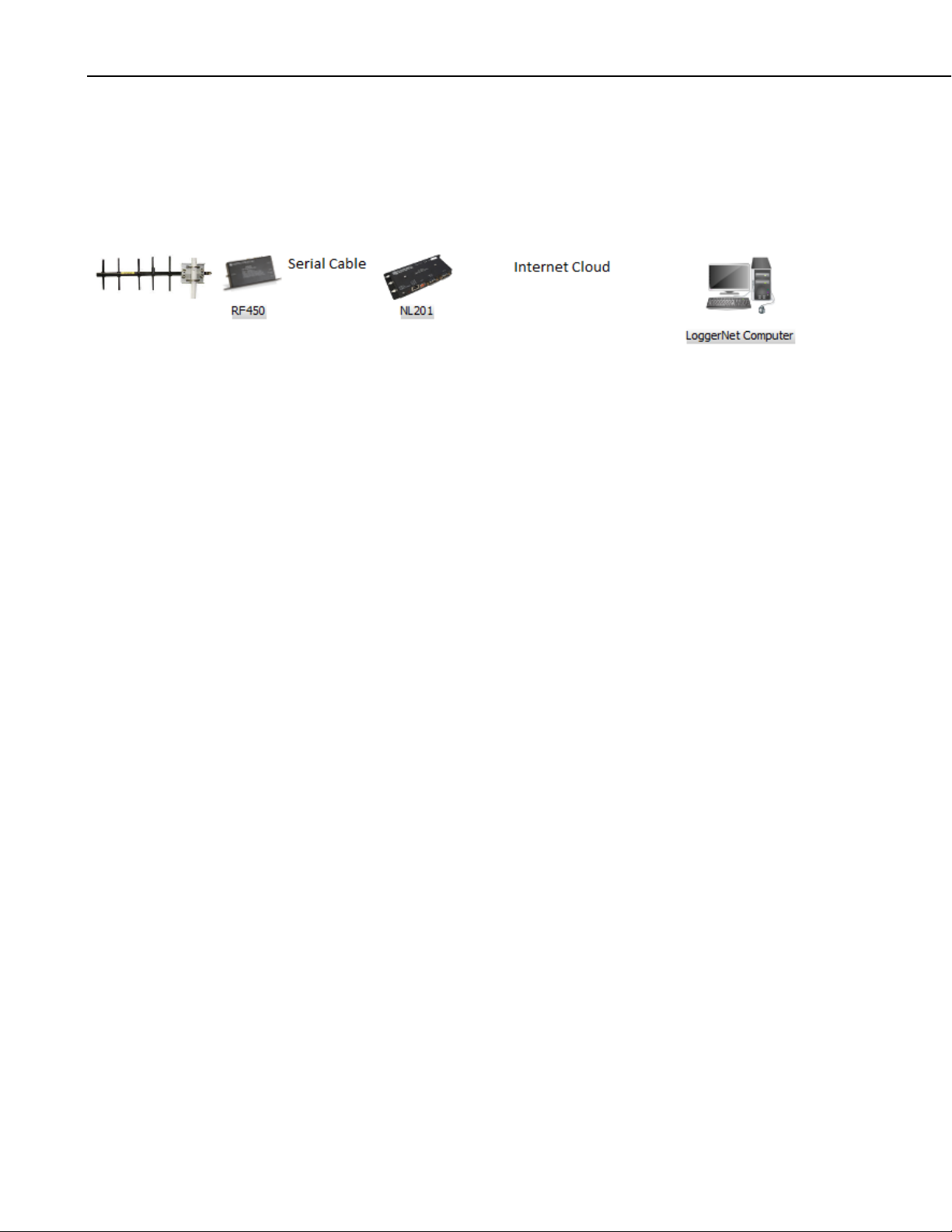
CRVW3 3-Channel Vibrating-Wire Datalogger
The RF450 will be coupled with an NL201 device to enable the TCP/IP or
internet connection. This allows the LoggerNet software to remotely drive the
RF450 base radio over the TCP/IP connection. In this way, LoggerNet can be
far away and out of radio range (at any location where reliable connectivity to
the internet is available), and still use the base station’s RF450 to communicate
with the CRVW3 devices on the radio network.
FIGURE 9-2. RF451 Network Base Station Configured for Remote
LoggerNet Connectivity
9.3.1 Deploying CRVW3 End-node Stations, Confirming Radio Connectivity
You should install individual radio-enabled CRVW3 devices at their field
locations by following the instructions in Section 8.2, Field Deployment of the
CRVW3. Ensure that the CRVW3-RF451 is configured as a Slave device using
DevConfig. Do this from the Settings Editor tab in DevConfig. Choose the
Radio tab. Now ensure that the Radio Operation Mode is set to Point to
Multipoint Slave. Ensure that the Radio Enabled setting is set to True. The
Radio ID setting should be a unique number for every CRVW3-RF451 being
deployed. Every CRVW3 should use the same Frequency Key and the same
Network ID. Press Apply if necessary.
After the CRVW3 has been installed, powered, and configured, you should
confirm that it can communicate over its radio (as described in Section 8.2.9,
Validating CRVW3 Radio Operation, and Section 8.1.7, Validating Radio
Connectivity in the Lab). Use a laptop running DevConfig and a portable
RF450 device configured as the master radio to complete this step.
From the CRVW3 location, confirm the line-of-sight path to the base station
site. Install a directional/Yagi antenna (pn 14201) unless the distance to the
base station is very short. Orient the Yagi antenna so that it points directly at
the base station.
9.3.2 Base Station Installation and Validation
Select a location for the base radio station that has good radio connectivity with
all the CRVW3-RF451 stations, as well as TCP/IP Ethernet access.
If the LoggerNet computer station will be co-located at the base station site, it
will connect directly to the RF450 with a serial cable.
Refer to Section 3.7 of the RF450 manual for details regarding the setup and
configuration of the RF450 radio portion of the master/base station.
s.campbellsci.com/documents/us/manuals/rf450.pdf
Ensure that proper power, enclosure, grounding, and mounting options are
available for permanently siting the base station. An omnidirectional antenna
44
Page 55

CRVW3 3-Channel Vibrating-Wire Datalogger
should be used, since the base station will communicate with more than one
CRVW3 station.
A serial cable should be connected from the RS-232 port of the RF450 radio to
the RS-232 port of the NL201 device. Refer to the NL201 manual for details
on how to configure it as a serial server:
s.campbellsci.com/documents/us/manuals/nl200.pdf. Once the base station is
enabled via the NL201, LoggerNet will use TCP/IP to communicate with the
base station.
Once the base station is installed and configured, you will use a laptop
computer running LoggerNet at the site to perform a validation. Configure
LoggerNet to use the base station according to the instructions in Section 9.3.3,
Configuring LoggerNet for Connectivity and Scheduled Collection, and
confirm that it can connect to and collect from the remote CRVW3 devices.
This should be done before leaving the base station site and travelling to the
remote LoggerNet location.
If your LoggerNet computer station is co-located at the base station location,
then configure the permanent computer station’s instance of LoggerNet per
Section 9.3.3, Configuring LoggerNet for Connectivity and Scheduled
Collection, instead of the laptop’s LoggerNet instance.
9.3.3 Configuring LoggerNet for Connectivity and Scheduled Collection
LoggerNet will first be used to confirm connectivity to each CRVW3 remote
station through the base station. After connectivity to each station is in place,
then LoggerNet can be configured to perform automatic (scheduled) data
collection.
In Section 9.3.2, Base Station Installation and Validation, the LoggerNet
computer station was configured with a physical-layer telemetry link to the
base station (or it was directly connected with a serial cable). The LoggerNet
software now needs to be configured with details about the CRVW3 devices on
your network and how it should connect to the base station. After that is
complete, the connectivity to individual CRVW3 stations can be confirmed.
Follow the configuration instructions given in Section 10.7.2, Configuring the
Network Map of LoggerNet, using the IPPort root device case (i.e., the
telemetry connection).
If LoggerNet connects to the base radio via serial cable, use the ComPort root
device case. Refer to Section 10.7.1, Physical Connection to the Base Station,
if a USB-to-serial cable is used between the LoggerNet computer and the
RF450 radio.
Skip the instructions at the end of Section 10.7.2, Configuring the Network
Map of LoggerNet, regarding repeater stations. You can optionally follow the
instructions in Section 10.7.3, Connecting to CRVW3 Stations, to confirm
connections to each CRVW3 station, though it probably isn’t necessary once
you can check the clock on each device. Next, you should follow the
instructions in Section 10.7.4, Setting up Automatic Data Collection, to set up
automatic data collection.
For details about the design and implementation of large or complex CRVW3
radio networks, see Section 10, Complex (Large) Radio Networks. Refer to
45
Page 56

CRVW3 3-Channel Vibrating-Wire Datalogger
Section 11, Operation of CRVW3 Networks, Section 12, Maintenance of
CRVW3 Networks, and Section 13, Troubleshooting CRVW3 Networks, for
information on how to operate, maintain, and troubleshoot CRVW3 radio
networks, such as those created using the process described in this section.
10. Complex (Large) Radio Networks
As the number of radio-enabled CRVW3 devices increases, or as more
complex terrain or other geographical constraints emerge within your system,
then additional consideration must be given to radio network design and
operation. Refer to Section 9, Radio Networks, for a basic definition of a radio
network. Refer to Section 9.1, Simple Radio Network Definition, to see if your
system requirements can be satisfied using a simple network design.
To implement a large radio network, it is important to understand in detail the
types of stations that can form the nodes of the network. Planning the network
layout (before hardware is purchased) becomes a necessity. Each station needs
to be deployed to its site properly followed by the validation of radio
communications. Station operation is confirmed using the LoggerNet software.
Proper deployment and configuration of the network ensures that the data
collection process operates smoothly.
10.1 Radio Network Station Types
Consider the six most common station types (network nodes) that are the
building blocks of a CRVW3 radio network:
1. LoggerNet computer station
2. Base radio station
3. CRVW3 end-node station
4. CRVW3 repeater station
5. Dedicated repeater station (repeater-only station)
6. Aggregating datalogger station
As you design the network, you must determine which station types are
required to measure all of your deployed sensors, and then you must ensure
that each station can adequately communicate with one or more adjacent
stations. Definitions and connectivity information are provided here for each
station type.
10.1.1 LoggerNet Computer Station
The costs associated with implementing and maintaining a radio network are
usually justified by the ability to automatically collect data from sensors in a
way that minimizes on-site technician visits. This automatic collection is
typically accomplished using LoggerNet software. To ensure the smooth
operation of your automatic collection process, you should plan to use a
computer that operates 24 hours per day and 7 days per week, is readily
available for establishing remote connections, and whose main purpose is to
constantly run the LoggerNet software. This is recommended even if you have
other copies of LoggerNet software running on desktop computers in your
office or on portable computers (laptops). To manage CRVW3 stations with
LoggerNet, you must have version 4.3 or later.
46
www.campbellsci.com/LoggerNet
Page 57

The computer running LoggerNet can be a Windows PC/server or it can be a
Linux server (Debian, RedHat, SuSE, CentOS, and related distributions). The
machine can be located in your office, or it can be maintained elsewhere in
your organization by IT personnel. It can run on the internet cloud (hosted or
virtual), or it can be located adjacent to your field deployment site. To
facilitate the hosted operation of LoggerNet, consider the use of the LoggerNet
Admin and LoggerNet Remote software packages (see the LoggerNet Packages
section of this brochure: s.campbellsci.com/documents/us/product-
brochures/b_LoggerNet4.pdf).
Because data collected from sensors is a key deliverable, you should plan
carefully so that a computer running LoggerNet with the above capabilities is
available for use. For most automatic data collection scenarios, only one
instance of LoggerNet is required. If the number of stations in your network
exceeds 85, then deploying multiple LoggerNet instances may improve data
collection performance.
10.1.2 Base Radio Station
The purpose of a base radio station (also called a “base station”) is to be a
gateway for communications between the radio network (which is your group
of multiple CRVW3 stations) and other devices that communicate with them
through some other communications medium. The LoggerNet computer is
typically the most important device that communicates with your radio network
via the base station.
CRVW3 3-Channel Vibrating-Wire Datalogger
FIGURE 10-1. CRVW3 Radio Network and Base Station Operation
47
Page 58

CRVW3 3-Channel Vibrating-Wire Datalogger
Only one base station is configured and used per radio network. It forms the
link between all devices on the network and any involved devices situated
outside the network.
The fundamental parts of a base station are a radio that can communicate with
the CRVW3 stations (RF450, RF451, or RF407) and then the means to
communicate outward to other devices. A base station can use a variety of
communications media for its outward facing connection — wired connections
(serial cable, phone modem, TCP/IP, RS-485), or another radio connection that
is different from the kind used by the CRVW3 stations (cell modem, WiFi,
VHF narrow-band, satellite, bluetooth).
Plan carefully how the base station will communicate with the LoggerNet
computer. Sometimes the LoggerNet computer and the base station can be at
the same location (forming a single station), and only a serial cable is used to
establish the connection between them. In other scenarios, a communication
device (such as an NL201 with a TCP/IP link) enables communications to
travel from the base radio outward to the LoggerNet computer at a remote
location.
10.1.3 CRVW3 End-node Station
A CRVW3 end-node station is a radio-enabled CRVW3 (i.e., with the –RF407
or –RF451 option) that communicates with only one other station. The single
remote (neighboring) station can be either a repeater station or the base station.
10.1.4 CRVW3 Repeater Station
A CRVW3 repeater station is a radio-enabled CRVW3 that communicates with
two or more other stations. The purpose of a repeater station is to relay radio
communications between other stations that cannot communicate with each
other directly. Stations can sometimes be out of range from each other or are
impeded by interfering geographic features.
It takes a little more time for communications to occur between the two
stations that use a repeater, although that delay usually doesn’t cause any
problems. To operate as a repeater station, the radio of the CRVW3 must be
configured as a repeater, and the IsRouter setting of the device should also be
set to “true” (see Section 8.1.5, Configuring the CRVW3, for how to configure
the IsRouter setting).
A CRVW3 repeater station can measure its own sensors (up to 3), store that
data, and communicate it back to the base station. It does this in addition to
passing radio messages between any of the remote stations with which it can
communicate.
10.1.5 Dedicated Repeater Station
A dedicated repeater station (also called a repeater-only station) is a radio
station whose only purpose is to relay radio communications between two or
more remote stations. It does not make measurements of its own. Because no
sensor measurements are required at the repeater location, this kind of station
provides a lower-cost connectivity option. All of its communications are
triggered by requests from remote stations to forward data to another station
with which that remote station cannot communicate directly. The main
component of this station is a radio that can communicate on the radio network
48
Page 59

with other CRVW3 stations and usually the base station. For a CRVW3-
NOTE
RF407 network, the repeating component is an RF407 radio+modem device.
For a CRVW3-RF451 network, the component is an RF450 or RF451
radio+modem device (see Section 10.2.6, Planning RF451 Radio Networks).
10.1.6 Aggregating Datalogger Station
An aggregating datalogger station is a CR6, CR3000, CR1000, or CR800 series
datalogger (www.campbellsci.com/dataloggers) whose purpose is to
communicate with multiple CRVW3 stations and collect data from them. A
radio that is compatible with the network must be integrated to this datalogger
(using an RF407, RF451, or RF450). Once data is collected from the remote
CRVW3 stations, it is stored on the datalogger (aggregated) so it can be
retrieved later by LoggerNet or other data collection agents. It is possible for
an aggregating datalogger station to also function as the base station of the
network, but it is not required.
An aggregating datalogger must use special instructions in its
CRBasic program to communicate with CRVW3 devices. For
more information about aggregating dataloggers, see
Aggregating Dataloggers.
CRVW3 3-Channel Vibrating-Wire Datalogger
Appendix C,
10.2 Planning the Radio Network
When automatic collection is used on a radio network, the data flows from the
sensors (which are the initial source of the data) all the way to the LoggerNet
computer station. You should determine what kind of station you need at every
step along that communications pathway. It is recommended that you plan
your network (at least with a preliminary analysis) before making your initial
hardware purchase.
FIGURE 10-2. CRVW3 Collected Data Flow
49
Page 60
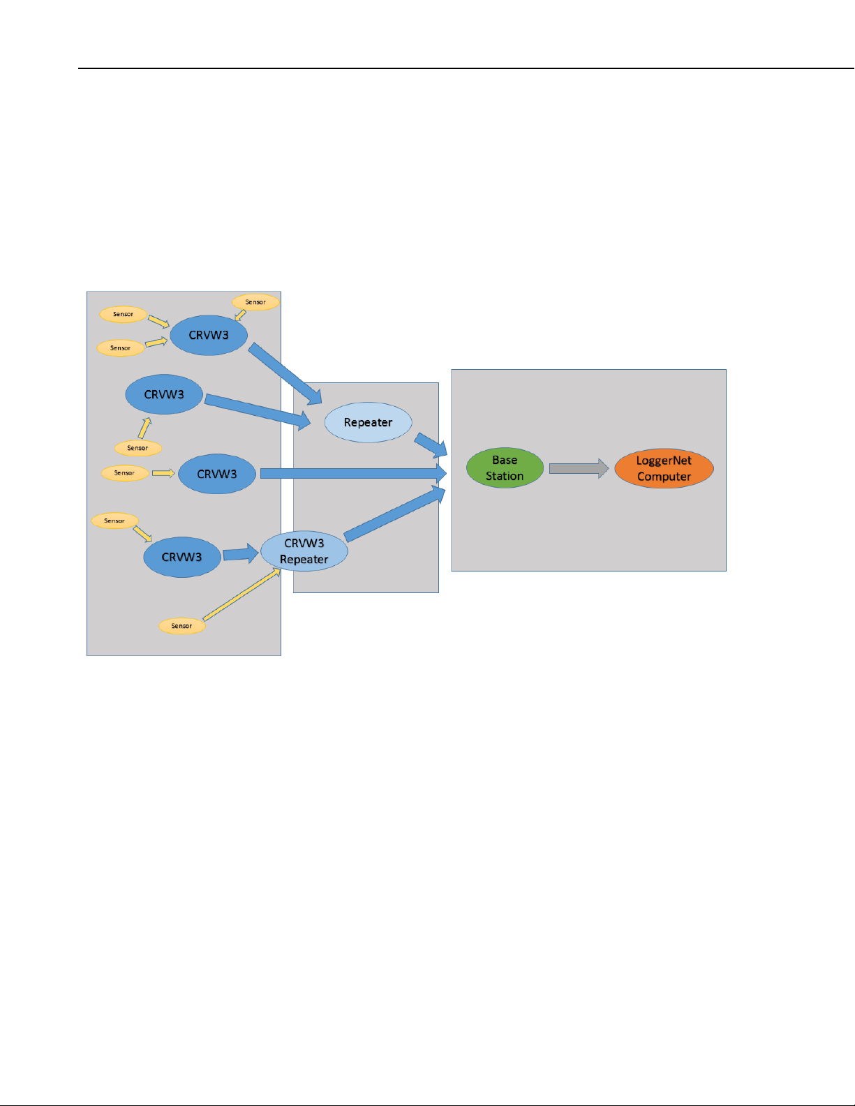
CRVW3 3-Channel Vibrating-Wire Datalogger
You can divide your network up conceptually into two sides and a center area.
On one side the sensors are measured and on the other side LoggerNet collects
the data. On the sensor side, you will start by identifying where sensors will be
located and where you will place CRVW3 stations to measure those sensors.
On the LoggerNet side, you should decide where the LoggerNet computer
station will be located and how it will communicate with the base radio station.
The location of the base station should also be determined. To bridge the two
sides of the network, you should determine where you need to set up CRVW3
devices as repeater stations, and where you should introduce dedicated repeater
stations.
50
FIGURE 10-3. Sensor Side and LoggerNet Side of a CRVW3 Network
The plan for your network should include an itemized list of:
• Sensors to be measured (Section 10.2.1, Sensor Planning)
• The CRVW3 devices required to measure all the sensors (Section
10.2.2, Planning for CRVW3 End-node Stations)
• The CRVW3 devices that will be configured as repeater stations
(Section 10.2.3, Repeater Planning)
• The dedicated repeater stations that are needed (Section 10.2.3,
Repeater Planning)
• The location of the LoggerNet computer station (Section 10.2.4,
LoggerNet Station Planning)
• The location of the base station (Section 10.2.5, Planning the Base
Station)
• Aggregating dataloggers, if needed (see Appendix C, Aggregating
Dataloggers)
Page 61

CRVW3 3-Channel Vibrating-Wire Datalogger
NOTE
NOTE
Since the planning of a radio network involves geographic decision making, it
is recommended that maps be created which indicate the geographic location of
each of these items.
Consider using the Network Planner tool as part of the
development of your network plan. The Network Planner is part
of the LoggerNet software package. With this tool, you can import
a graphical map (JPG or PNG format) of the area and use that as
a background for the designer canvas. Then you can place
CRVW3 devices and other hardware onto the map/canvas at the
desired locations. After that you can plan out how connectivity
will occur between the CRVW3 devices, repeaters, the base
station and the LoggerNet computer. Once a plan is created it can
be saved to a computer file and retrieved later on when it is time
to configure your hardware. The tool can be used as a replacement
for DevConfig for configuring the device settings of multiple
hardware devices in a coordinated way. Please refer to the
LoggerNet manual Section 4.3 for more information about the
Network Planner.
s.campbellsci.com/documents/us/manuals/loggernet.pdf
10.2.1 Sensor Planning
It is possible to design a network inside of LoggerNet that includes
many other data acquisition devices (other dataloggers,
communications peripherals, non-vibrating-wire sensors, etc.)
mingled together with CRVW3 devices and related hardware.
Within LoggerNet, the CRVW3 has functionality typical of other
mainstream dataloggers, and it will act as expected for those
familiar with datalogger behavior inside that software. Although
mixed networks like this can operate properly, and it is expected
that many users will utilize networks with this kind of
heterogeneous design, this manual will focus only on the details
of setting up CRVW3-based data collection networks.
The ultimate objective of a CRVW3 network is to measure vibrating-wire
sensors and relay that data back to LoggerNet. You should plan out, preferably
using maps or other location-based diagrams, where each vibrating-wire sensor
will be located. You should finalize how many sensors will be measured. You
should know which sensors are already deployed into the field, and which
sensors will need to be procured and installed. You should document the make
and model of each sensor, and what output units are desired for its
measurement. You should know whether each sensor has a built-in thermistor
or not. You should ensure that manufacturer documentation for each sensor
type is available. Any cabling that is already connected to the sensor should be
documented (type and length). Implementing a naming convention for sensors
is often helpful. Installation of sensors should be planned out in accordance
with the installation guidelines specified by the sensor manufacturers.
The CRVW3 measures mainstream, single-coil circuit vibrating-wire sensors.
These sensors are readily available from multiple well-known vendors within
the industry. Campbell Scientific support personnel can give brief guidance, if
51
Page 62

CRVW3 3-Channel Vibrating-Wire Datalogger
needed, on what measurements can be made with vibrating-wire sensors and
what sources can be used to procure them. A Geotechnical Instrumentation
class is available from Campbell Scientific’s world headquarters in the United
States that discusses vibrating-wire measurement sensors and systems.
www.campbellsci.com/training
10.2.2 Planning for CRVW3 End-node Stations
Using the locations mapped in Section 10.2.1, Sensor Planning, plan out how
each sensor will connect with a CRVW3 device. To minimize the required
number of stations, plan for three sensors to connect to each CRVW3
whenever possible. Indicate on a map where the CRVW3 stations will be
located.
52
FIGURE 10-4. Each Sensor Connects to a CRVW3
The length of cable between the sensor and the CRVW3 is a factor to consider.
The distance between the CRVW3 and the measured sensor can be up to
1600 m in many instances. Long cable distances (> 500 m) should be validated
for proper operation using careful field experimentation. Cabling distances
shorter than 500 m can usually work well with lower excitation levels (5 V
instead of 12 V) which saves on power consumed during the measurement
cycle. Document the length of cabling that will enable each sensor to connect
with a CRVW3.
Plan for each CRVW3 to have a line-of-sight radio connection with a repeater
station (which can be another CRVW3) or with the base station. A CRVW3
end-node station will communicate with only one remote radio station. The
location of a CRVW3 may need to be adjusted to allow for a satisfactory radio
communications link. Some field-based groundwork may be necessary to
determine radio strength capabilities between potential station sites (see
Section 10.2.7.1, Pre-procurement Field Visits).
Page 63

If the remote station is within a close enough distance to the CRVW3, a whip
antenna can be used. However, for longer distances a high-gain antenna will
be needed. A Yagi antenna is recommended for a CRVW3 end-node station
because of its high gain and directional beaming capability.
For specific information relating to CRVW3-RF451 end-node stations, see
Section 10.2.6, Planning RF451 Radio Networks.
10.2.3 Repeater Planning
A repeater station can be implemented using a CRVW3 station or it can be a
dedicated repeater station (repeater-only station). If it makes sense to measure
one or more vibrating-wire sensors near the proposed repeater site, then deploy
a CRVW3 repeater, otherwise plan for a dedicated repeater station.
Design your network with repeater stations in strategic locations to overcome
line-of-sight problems or signal strength difficulties in the network. A
CRVW3 end-node station may be too far away from the base station to
communicate properly, or blocked from the base station by interfering
geographic features. In those cases, the CRVW3 end-node should route its
radio communications through a repeater station to reach the base station. In a
few cases, multiple repeaters may be needed to establish a route from a
CRVW3 end-node to the base station.
CRVW3 3-Channel Vibrating-Wire Datalogger
You should make a field visit to validate your planned repeater site locations
(see Section 10.2.7.1, Pre-procurement Field Visits).
Each conveyance of data from one station to another is called a “radio hop” or
simply a “hop”. A CRVW3 end-node that communicates directly with the base
station is said to have a “single-hop” link. When a CRVW3 end-node
communicates with the base station via one repeater station it is said to have a
“dual-hop” or “2-hop” link. When an end-node routes through two or more
repeaters, then it is referred to as a “multi-hop” link.
A repeater station is always required to communicate with multiple remote
stations, therefore an omnidirectional antenna should be used on the station
(often called an “omni” antenna).
You should designate on the map of your network plan which CRVW3 devices
will act as repeater stations. You should also identify the locations of any
dedicated repeater stations.
For specific information relating to CRVW3-RF451 repeaters and RF450based dedicated repeaters, see Section 10.2.6, Planning RF451 Radio
Networks.
10.2.4 LoggerNet Station Planning
When planning your network, you need to finalize the location of the computer
that will permanently run the LoggerNet software and which will operate as the
first-stage permanent data repository (see Section 10.1.1, LoggerNet Computer
Station). One of the key factors to consider when making this decision is how
the base station will communicate with the LoggerNet computer.
If you choose to deploy the LoggerNet computer in the field, within radio range
of some or all of the CRVW3 stations, then the LoggerNet computer will be
53
Page 64

CRVW3 3-Channel Vibrating-Wire Datalogger
co-located with the radio base station. In that case, only a serial cable is
needed to connect between the computer and the base station’s radio device.
LoggerNet controls the base radio via the serial cable to make connections with
all CRVW3 devices. Consider that a protective location must be procured for
the LoggerNet computer, power provided, and that some sort of network
connectivity between LoggerNet and your office location must be established.
Sometimes an office building is within radio distance of some of the CRVW3
devices and some of the repeaters. In that case, LoggerNet can run in the
office, and steps are taken to mount an antenna for use by the base radio
somewhere on the exterior of the office building. The antenna cable is fed
through to the base radio, which is located inside the building near the
LoggerNet computer and connected via a serial cable.
Another option is to utilize a TCP/IP, Wi-Fi, Cell Modem, RS-485 or other
kind of communications link (different from the radio links) in the field
location that will connect between the base station’s radio and LoggerNet at a
remote location. In these scenarios, LoggerNet is located at the office or at a
hosted site and uses TCP/IP (or another data protocol) to make a remote
connection to the base radio station. The base station is located somewhere
within range of the CRVW3 devices and the repeaters. The base station in this
instance contains its main radio but also hosts another device. This can be an
NL201 (or similar serial-to-Ethernet bridge), an NL240 (or other serial-to-WiFi bridge), an LS300G (or similar cell modem to TCP/IP gateway), or an MD485 for enabling RS-485 wired communications. The base radio and the
bridging device are linked together. When installed in this way, LoggerNet can
control the base radio via TCP/IP (or other data protocol) even though the two
stations are located at a significant distance from each other.
If multiple persons need to interact with the same LoggerNet computer in your
office, you should strongly consider the use of LoggerNet Admin (installed on
the LoggerNet computer or server), and LoggerNet Remote (which is installed
on an individual’s workstation PC in the office and connects as a client to
LoggerNet Admin). See Section 10.1.1, LoggerNet Computer Station, or
www.campbellsci.com/LoggerNet for more information.
Once the location of the LoggerNet computer station is known, indicate it on
the map of your network plan, and begin making arrangements for the other
items necessary for it to connect with the base station.
10.2.5 Planning the Base Station
The location of the base radio station should be selected carefully. The base
station must have good radio connectivity with all repeater stations and with as
many CRVW3 end-node stations as possible. In addition, it must be able to
communicate with the LoggerNet computer station. The main purpose of the
base station is to be a bridge or gateway between your CRVW3 radio network
and the rest of the world (any other remote devices that need to communicate
with your CRVW3 devices). Please refer to the diagram in Section 10.1.2,
Base Radio Station.
Usually a base station requires an omnidirectional antenna since it
communicates with multiple remote stations. In the less-common case where
the base station communicates with only one remote repeater (through which
all other stations route), then a directional antenna (Yagi) can be used.
54
Page 65

CRVW3 3-Channel Vibrating-Wire Datalogger
NOTE
NOTE
LoggerNet is usually the main device outside the radio network that
communicates with the base station. Choose a location that allows the base
station to establish a link to the LoggerNet computer station. Sometimes the
LoggerNet computer and the base station are at the same location. In other
deployments, they are remotely located and communicate via a TCP/IP
telemetry device, or similar. For more information about making connections
between LoggerNet and the base station, see Section 10.2.4, LoggerNet Station
Planning.
When planning for an aggregating datalogger (Section 10.1.6
Aggregating Datalogger Station) to be part of your network,
including an aggregator that can operate as the base station, see
Appendix C, Aggregating Dataloggers.
Once the location of the base radio station is determined, indicate it on the map
in your network plan.
10.2.6 Planning RF451 Radio Networks
The CRVW3 can be purchased with the –RF451 communications option (i.e.,
as a CRVW3-RF451). This manual refers to the radio networks used by
CRVW3-RF451 devices as RF451 radio networks. The following devices can
be used to create a functioning station within an RF451 radio network:
• CRVW3-RF451
• RF450 radio+modem (pn 18326, www.campbellsci.com/rf450)
It is anticipated that Campbell Scientific, Inc. will release products in the future
that will also operate as part of an RF451 radio network:
• RF451 (stand-alone radio+modem with functionality similar to the
RF450)
• CR6-RF451 (CR6 datalogger with built-in RF451 radio)
,
Certain compatible radio devices available from Freewave
(www.freewave.com) can also be configured to operate in an
RF451 radio network. Call your Campbell Scientific support
representative for more details.
Every RF451 network requires one radio to be defined as the master radio.
This master radio is the main component of the base station, i.e., the base
station is defined as the station that controls the master radio. Communications
entering or exiting the RF451 network are routed through the master radio
station. Usually the RF450 will be used as the master radio in the base station
of an RF451 radio network. The RF450 can also be used to create dedicated
repeater stations in an RF451 network. CRVW3-RF451 end-node stations are
defined and configured as Slave stations. CRVW3-RF451 repeater stations are
defined and configured as Slave/Repeater stations.
You should rent the RF450 Test Kit (pn 21108) to perform in-field site
exploration and radio link strength testing when designing an RF451 radio
network.
55
Page 66

CRVW3 3-Channel Vibrating-Wire Datalogger
Please refer to the RF450 manual for more information about the use of the
RF450:
s.campbellsci.com/documents/us/manuals/rf450.pdf
Sections 3.9 and A.2 of the RF450 manual provide details about the
configuration of RF450 dedicated repeater stations.
10.2.6.1 Base Station Design for RF451 Radio Networks
For most base station designs on an RF451 radio network, the RF450
radio+modem device should be used. It is configured as the master radio when
implemented as the main component of base station.
When LoggerNet is co-located with the base station, a serial cable makes the
connection between the RF450 radio and the LoggerNet computer. The
physical configuration of the base station has this form:
Antenna <--> RF450 <--> RS-232 serial cable <--> LoggerNet computer
When a telemetry device is used to make a remote connection between the
RF450 base station and the LoggerNet computer, the serial communications
between them are transmitted over a different medium. The following physical
configurations illustrate the use of TCP/IP connections made through wired
Ethernet, Wi-Fi, or Cell-modem media:
Antenna <--> RF450 <--> NL201 <--> InternetCloud <--> LoggerNet
computer
Antenna <--> RF450 <--> NL240 <--> WiFi Router <--> InternetCloud <-->
LoggerNet computer
Antenna <--> RF450 <--> LS300G <--> Cell Tower <--> InternetCloud < -->
LoggerNet computer
Other cell modems could be substituted for the LS300G, other Wi-Fi-to-serial
devices for the NL240, and other serial-to-TCP/IP devices for the NL201.
Phone modems could also be used or other telemetry options.
56
Antenna <--> RF450 <--> Any RS-232-based telemetry option <--> LoggerNet
computer
s.campbellsci.com/documents/us/product-brochures/b_telecommunications.pdf
Page 67

CRVW3 3-Channel Vibrating-Wire Datalogger
It is possible to designate the CRVW3 as the master radio of an RF451 radio
network, and use it as the base station. This should only be done if a
permanent USB cable connection can be maintained between the base CRVW3
and the LoggerNet computer. It is expected that this configuration will be used
only rarely. The physical configuration of the base station will have this form:
Antenna <--> CRVW3-RF451 set as Master <--> USB cable connection <-->
LoggerNet computer
10.2.7 Plan Validation and Hardware Procurement
Once you have documented your implementation plan for sensors, and planned
out your CRVW3 station sites, repeaters, base station, and LoggerNet computer
station, then you should make a field visit to validate radio link feasibility.
You should also get feedback about your plan from others. Slight
modifications to your plan may be necessary. After these activities are
complete you should be ready to place an order to procure your hardware.
10.2.7.1 Pre-procurement Field Visits
It is best to confirm your radio network plan with a visit to the field. One of
your main tasks is to confirm line-of-sight visibility between proposed radio
station locations. Consider using a CSI Demo Kit (for example, pn 21108) that
corresponds the kind of radio network you are designing. This will allow you
to work out radio connectivity issues and the types of antennae needed before
procuring hardware. Using the kit, you set up a temporary radio station at two
different sites and measure the connectivity strength between them. End-node
stations use Yagi antennae and repeater stations (and usually the base station)
use Omni antennae. These are also used as part of the test.
There are several key factors that can influence the quality of a radio
communications link. Some are mentioned here:
Radio Power: Different radio types have different broadcast power options.
The RF450 radio and the CRVW3-RF451 can broadcast at power ratings
configurable up to 1 watt. Practical links can be established at distances of 21
km (13 miles). The RF407 and CRVW3-RF407 operate at a maximum power
of 250 milliwatts, and have a practical range of several miles. In conditions that
are closer to the ideal, longer distance links can be achieved.
Seasonal Vegetation Changes: Sometimes seasonal changes to the
environment can impact the quality of a radio communications link. For
example, if a radio link is tested in the winter when trees have no leaves, then it
may not operate as well in the summer when leaves are on the trees. When
choosing a site for a station, consider any factors in the environment that may
change seasonally.
Reflective Interference and Fresnel Zones: Because transmissions from an
antenna radiate outward in multiple directions, radio wave pathways sometimes
get reflected in a way that causes destructive interference at the receiving
location. Water surfaces, some kinds of flat landscape/ground, or other flat
features can reflect radio waves and cause this type of signal degradation. A
Fresnel zone helps to identify the height at which an antenna should be placed
to maximize signal strength between two stations. In the field, you can
experiment by raising (or sometimes lowering) the antenna to maximize the
57
Page 68

CRVW3 3-Channel Vibrating-Wire Datalogger
NOTE
radio link strength. For more information, see
en.wikipedia.org/wiki/Fresnel_zone.
10.2.7.2 Plan Validation with Others
It can be helpful to share your radio network plan with others. This process
may uncover items that require additional planning. There may be others in
your organization that have experience deploying and operating radio
networks. Contact your local Campbell Scientific support representative to
discuss your plan and any questions or concerns you may have with it. When
using the Network Planner software, a saved *.NWP file can be provided to
Campbell Scientific or others for review.
Ensure that you have the right antenna types selected for each station.
Mounting hardware may be needed for repeater stations and the base station.
Review the items discussed in Section 8.2, Field Deployment of the CRVW3,
for each station.
10.2.7.3 Hardware Procurement
Using your network plan as a resource, contact your local Campbell Scientific
representative to place an order for the required hardware. The ordering
process brings a number of items into the discussion that are usually needed for
typical deployments.
10.3 Deployment Strategy
Once the hardware for your CRVW3 radio network arrives, it needs to be
configured, validated, and deployed to the field.
10.3.1 Radio Network Lab Validation
You should connect to each CRVW3 individually in the office or lab and
configure it (See Section 8.1, Lab Connection and Configuration). However,
you should also set up at least part of your radio network and validate it in the
lab, if possible. Install and configure LoggerNet on a temporary or portable
computer. Set up a base station, and confirm that it can communicate with a
few CRVW3 stations. Set up a repeater station and ensure it works. Refer to
Sections 10.4 through 10.7 for details about how this is done.
Consider the use of the Network Planner when configuring your
devices in the lab. After the devices are placed onto the canvas of
the Network Planner software and settings are specified, then the
software provides a way to connect to each device individually (in
turn) and configure it. It operates in a similar manner to Device
Configuration Utility, except that the settings are pushed into the
device in a more automated manner. A checklist guides you
through the process of isolating each device one at a time and
connecting it to your computer to be configured. See Section
Planning the Radio Network, for more information about the
Network Planner.
10.2,
58
Page 69

CRVW3 3-Channel Vibrating-Wire Datalogger
10.3.2 Field Deployment Considerations
For larger networks, you should develop a strategy specifying the order of
operations for deploying your stations. Each CRVW3 radio network consists
of: one LoggerNet station, one base station, one or more CRVW3 end-nodes,
and one or more repeater stations. Some CRVW3 end-nodes require repeaters
to communicate, while others communicate directly with the base station
(single-hop).
In most cases it is helpful to install repeater stations and the CRVW3 devices
that require them at the end of your deployment cycle. By ensuring during the
first part of your deployment that single-hop CRVW3 devices are operating
properly with the base station and with LoggerNet, then the level of complexity
is reduced for the repeater station validation process.
One common approach would be to first install the CRVW3 end-nodes that
connect directly with the base station, followed by the installation of the base
station itself and then the installation of the permanent LoggerNet station.
With those items in place and functioning, then attention can be given to
installation of the CRVW3 devices that require repeaters and the actual
repeater sites.
Another approach would be to install the base station first, followed by the
CRVW3 end-nodes that connect directly to the base station. After that the
LoggerNet station can be configured and validated. Installation of CRVW3
stations requiring repeaters and the actual repeater sites would be last.
Single-hop CRVW3 End-node-first approach
1. CRVW3 end-nodes that connect directly to base station (single hop)
2. Base Station
3. LoggerNet
4. CRVW3 end-nodes that connect via repeaters
5. Repeaters
Base Station-first approach
1. Base Station
2. CRVW3 end-nodes that connect directly to base station (single hop)
3. LoggerNet
4. CRVW3 end-nodes that connect via repeaters
5. Repeaters
After the physical installation of the hardware at a site location, the
configuration of each station requires validation. You want to make sure that
radio communications and related functions are working properly before
leaving the site.
To confirm that a station is working properly, you need to control elements of
the CRVW3 configuration, elements of the base station configuration, and
elements of the LoggerNet configuration all at the same time. Sometimes this
is coordinated through the use of multiple technicians at different stations that
communicate using voice cell phones or voice radios. However, another
option is to employ temporary versions of system components that are brought
with you to the station installation site.
59
Page 70

CRVW3 3-Channel Vibrating-Wire Datalogger
For instance, when installing a CRVW3 station, bring a laptop running
LoggerNet with a serial cable that connects to a base radio. This will be the
temporary “LoggerNet and base radio” station, and it will help to confirm
proper CRVW3 operation. When installing a base radio site, bring a laptop
running LoggerNet that can make a wired serial connection to the base radio
being deployed, and also bring a temporary CRVW3 device which will
communicate with the base radio and validate it. The amount of time saved by
having these temporary devices available can be substantial.
10.4 Deployment of CRVW3 Radio Stations
You should install individual radio-enabled CRVW3 devices at their field
locations by following the instructions in Section 8.2, Field Deployment of the
CRVW3. After a device has been installed and powered, you should confirm
that it can communicate over its radio (Section 8.2.9, Validating CRVW3 Radio
Operation, and Section 8.1.7, Validating Radio Connectivity in the Lab).
Using a temporary base station radio and laptop running LoggerNet, you
should confirm that LoggerNet can connect to the station and collect data from
it. See Section 10.7, LoggerNet Configuration, for details about how to
configure and use LoggerNet to do this. Be sure to place the base radio more
than 25 feet away from the CRVW3 antenna to avoid interference.
Confirm the line-of-sight path to the permanent base station site (or repeater
station site). A CRVW3 end-node station will communicate with only one
remote radio station. If that station is distant, use a Directional/Yagi antenna
(pn 14201). Orient the antenna so that it points directly at the remote station.
You may need to experiment with antenna height to get the best link strength
possible (see Section 10.2.7.1, Pre-procurement Field Visits).
If the CRVW3 station will operate as a repeater station, see instructions in
Section 10.6, Repeater Station Deployment.
When several or all of the CRVW3 end-node stations have been installed and
confirmed as working, then connectivity with the permanent base station
should be validated at the base station location. (See Section 10.5, Base
Station Deployment.)
10.4.1 CRVW3-RF451 Deployment
When the CRVW3-RF451 is deployed as an end-node in the network, ensure
that is configured as a Slave device using DevConfig. (See Section 10.2.6,
Planning RF451 Radio Networks.) From the Settings Editor tab in
DevConfig, choose the Radio tab. Now ensure that the Radio Operation Mode
is set to Point to Multipoint Slave. Press Apply if necessary. See Section 10.6,
Repeater Station Deployment, if the station is a repeater.
60
Page 71

CRVW3 3-Channel Vibrating-Wire Datalogger
Ensure that the Radio Enabled setting is set to True. The Radio ID setting
should be a unique number for every device on the RF451 network (end-node,
repeater, and base station). Often it is convenient to set it to the same number
as the PakBus Address, though that is not required. Every device on the
network should use the same Frequency Key and the same Network ID. To
understand how to use the other settings on the Radio and Radio Advanced
tabs, refer to the topical help in DevConfig, or to the RF450 manual
(s.campbellsci.com/documents/us/manuals/rf450.pdf).
While on-site, use a portable (temporary) RF450 device configured as the
master radio and connected to LoggerNet running on a laptop to confirm proper
radio operation of the station. (See Section 10.4, Deployment of CRVW3 Radio
Stations, and Section 10.7, LoggerNet Configuration.) Connect to the station
and collect data.
10.5 Base Station Deployment
The base radio station used in a CRVW3 network has two communications
pathways. One is the radio pathway that is used to communicate with CRVW3
end-node stations and repeater stations. The other is the pathway to LoggerNet
and other remote devices that may require connectivity with the radio network.
Local LoggerNet computer stations connect to the base station using a serial
cable. Details for making a telemetry communications link between the base
station and LoggerNet are specific to the kind of radio device used on the base
station. See Section 10.5.1, Base Station on the RF451 Network, for more
information.
A typical base station consists of a radio device that is compatible with the
CRVW3 devices on the network (RF407, RF450, or RF451). For stations that
make a remote connection to LoggerNet, a telemetry device for that purpose is
also part of the station. You should ensure that proper power, enclosure,
grounding, and mounting options are available for the station. An
Omnidirectional antenna should be used, since the base station usually
61
Page 72
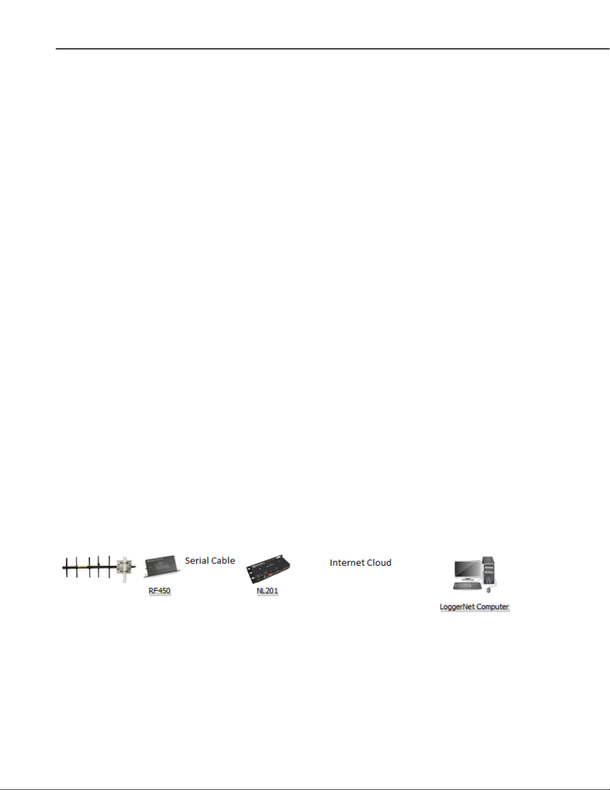
CRVW3 3-Channel Vibrating-Wire Datalogger
communicates with more than one remote radio station. Consult the manual
for the applicable radio device to obtain detailed instructions for setting up the
radio portion of the base station.
A CRVW3 device itself is not usually used as the base station in a CRVW3
network. This should only be done if a permanent USB cable connection can
be maintained between the base CRVW3 and the LoggerNet computer. It is
expected that this configuration will be used only rarely.
Once the base station is set up and configured, you can use a temporary
CRVW3 station located with you at the site to confirm operation of the base.
You will also need to configure the LoggerNet station if it is co-located with
the base station, or use a portable/laptop computer running LoggerNet to
perform the validation. Configure LoggerNet to use the base station (see
Section 10.7, LoggerNet Configuration), and confirm that you can connect to
the temporary CRVW3 station and collect data from it. If CRVW3 end-node
stations have already been deployed, LoggerNet can be configured to connect
to and collect from those devices as well. Be sure to place the temporary
CRVW3 more than 25 feet away from the base station antenna to avoid
interference.
10.5.1 Base Station on the RF451 Network
The RF450 radio should typically be used as the main component of the base
station in an RF451 network. The RF450 will be configured as the master
radio. Refer to Section 3.7 of the RF450 manual for details regarding the setup
and configuration of the RF450 radio portion of the master/base station.
s.campbellsci.com/documents/us/manuals/rf450.pdf.
The base radio should connect to LoggerNet either through a serial cable or via
a telemetry device such as the NL201, NL240, or LS300G. When using
telemetry options, a serial cable is typically connected from the RS-232 port of
the RF450 radio to the RS-232 port of the telemetry device. The telemetry
device should usually be configured as a serial server. When using Campbell
Scientific telemetry devices, the device can be configured as a PakBus router
instead. Consult both the RF450 manual and the manual for your specific
telemetry device for details about how to connect and configure these devices
to work together. Once the base station is enabled via telemetry, LoggerNet
will usually use TCP/IP to communicate with the base station.
s.campbellsci.com/documents/us/manuals/nl200.pdf
62
s.campbellsci.com/documents/us/manuals/nl240.pdf
s.campbellsci.com/documents/us/manuals/ls300g.pdf
When connecting the RF450 base radio directly to the LoggerNet computer,
connect the serial cable to the RS-232 port of the RF450, and configure it with
DevConfig as instructed in the RF450 manual. See Section 10.7.1, Physical
Connection to the Base Station, for more information.
Page 73

CRVW3 3-Channel Vibrating-Wire Datalogger
As indicated in Section 10.2.6.1, Base Station Design for RF451 Radio
Networks, the CRVW3 itself is rarely used as the base radio station in an
RF451 Network. However, to use that configuration, ensure that the Radio
Operation Mode setting in the Radio tab of DevConfig is set to Point to
MultiPoint Master. Also set the IsRouter setting located in the PakBus tab of
the Settings Editor tab in DevConfig to True.
Use a temporary CRVW3 station and LoggerNet to validate the operation of
your deployed RF450 base station before leaving the site (see Section 10.5,
Base Station Deployment, above).
10.6 Repeater Station Deployment
A repeater station in a CRVW3 radio network can be either a CRVW3 station
configured as a repeater, or a dedicated repeater station.
To configure a CRVW3 station as a repeater station, follow the steps outlined
in Section 10.4, Deployment of CRVW3 Radio Stations, but use an
omnidirectional antenna (pn 14221) instead of a directional/Yagi antenna.
Additionally, set the IsRouter setting located in the PakBus tab of the Settings
Editor tab in DevConfig to True. See Section 10.6.1, Repeaters on RF451
Networks, for additional configuration steps required when using the CRVW3-
RF451 as a repeater.
For dedicated repeater stations, the stand-alone radio that matches the radio
type of your CRVW3 stations should be used (RF407, RF450, RF451).
Consult the manual for that radio device for instructions on setting up and
configuring a repeater station. You should ensure that proper power,
enclosure, grounding, and mounting options are available for the station.
If CRVW3 end-nodes have already been deployed that rely on this repeater site
being installed and configured, then you can test it before leaving the site (see
Section 10.3.2, Field Deployment Considerations). Use a temporary base
station and laptop running LoggerNet to connect to one or more of the remote
CRVW3 sites through the repeater. (See Section 10.7, LoggerNet
Configuration, for LoggerNet configuration details). Be sure to place the base
radio more than 25 feet away from the repeater antenna to avoid interference.
Validation of the repeater station by performing a test at the permanent base
station location is also recommended. Travel to the base station location, and
then use the process outlined in Section 10.5, Base Station Deployment, but use
the remote CRVW3 (routed through the repeater) as the test device instead of
the local/temporary CRVW3.
10.6.1 Repeaters on RF451 Networks
When using a CRVW3-RF451 as a repeater station, ensure that the Radio
Operation Mode setting in the Radio tab on the Settings Editor tab in
DevConfig is set to Point to MultiPoint Slave/Repeater. Also see instructions
in Section 10.6, Repeater Station Deployment.
When using a dedicated repeater station on an RF451 Network, use the RF450
radio as the main component of the station. Consult the RF450 manual Section
3.9 for details about the configuration of the radio as a repeater device
(s.campbellsci.com/documents/us/manuals/rf450.pdf). See also Section 10.6,
Repeater Station Deployment.
63
Page 74

CRVW3 3-Channel Vibrating-Wire Datalogger
NOTE
10.7 LoggerNet Configuration
The use of LoggerNet for testing and validating deployed stations in your
CRVW3 network is critical. For LoggerNet to work properly, the computer
running LoggerNet must first be physically connected to the base radio station
or configured with a telemetry link to the base station. The LoggerNet
software is then configured with details about the CRVW3 devices on your
network, enabling connectivity. Once you can connect to and collect data
manually from each CRVW3 station on your network, you should configure
LoggerNet to execute data collection automatically (often called “Scheduled
Data Collection.”)
10.7.1 Physical Connection to the Base Station
For wired connections between the LoggerNet computer and the base station,
use a serial cable. If the computer running LoggerNet has a dedicated RS-232
COM port, you can use a standard DB9 serial cable to make the connection
(pn 10873). If your LoggerNet computer does not have a dedicated RS-232
port, you can use a USB-to-Serial conversion cable (pn 17394) utilizing a USB
port on the computer. Connect the serial cable to the RS-232 port of the radio
used at the base station. You should note which COM port is being used by
your serial cable. For USB-to-serial converter scenarios, a USB driver is active
which will indicate the specific port number being used when the device is
plugged in.
For details about establishing a telemetry link between LoggerNet and the base
station see Section 10.5.1, Base Station on the RF451 Network. Once
configured, most telemetry links will use a TCP/IP connection to send data
between LoggerNet and the base station.
10.7.2 Configuring the Network Map of LoggerNet
Once a serial or telemetry link between LoggerNet and the base station is
physically established, then LoggerNet needs to be configured to enable
communications to occur through the base station and outward to the remote
CRVW3 stations. The Setup (Setup Screen) program in LoggerNet is used to
create a tree-list of CRVW3 stations and their connectivity attributes, as well as
details for related hardware. This list of devices shows in multiple locations
throughout the software and is called the Network Map of LoggerNet.
If the Network Planner was used to configure your network of
CRVW3 devices, there is also a function in that software to
configure the Network Map of LoggerNet so that it can
communicate with the base station and the CRVW3 devices. Note
the checkbox for configuring LoggerNet located in the Configure
Devices checklist on the main screen. Once that task is executed,
you will see the results of this configuration show up
automatically in the SetupScreen of LoggerNet. This enables you
to bypass the manual steps shown in this section. Refer to the
LoggerNet manual Section 4.3 for more information about the
Network Planner.
64
s.campbellsci.com/documents/us/manuals/loggernet.pdf
Page 75

CRVW3 3-Channel Vibrating-Wire Datalogger
The Setup application is found on the Main section of the Toolbar which
appears when LoggerNet is first started. Click the blue “wrench and
screwdriver” icon to start the application:
If the Setup Screen comes up in the EZSetup Mode,
then click the Std View button to put it into the Standard View Mode:
65
Page 76
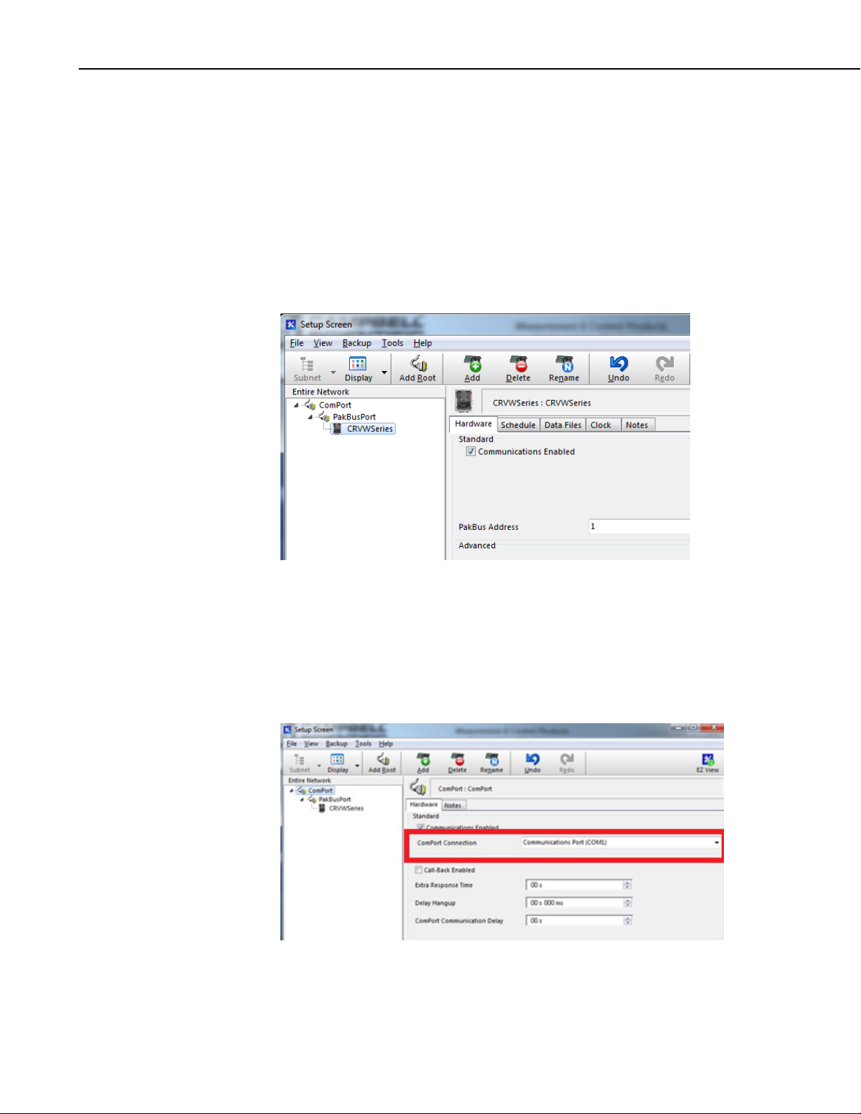
CRVW3 3-Channel Vibrating-Wire Datalogger
First, add a root device to the network map by pressing the Add Root button.
When using a serial cable (local) connection to the base station, then you
should select ComPort for the type of root device. If you have a telemetry
connection between LoggerNet and the base station, you will usually choose
IPPort as the root device. From the next list that is presented, choose
PakBusPort (PakBus Loggers)… .
You will then be presented with a list of dataloggers. Choose CRVWSeries,
then press the Close button.
Assuming you started with an empty network map, you should now see
something like this on the left side of the screen (Entire Network box):
The ComPort or IPPort root device is the object used to establish a link with
your base station.
Click on the ComPort device in the Network Map (Entire Network) pane, and
note the Hardware tab in the right hand pane. Use the drop-down selection
box called ComPort Connection to choose the serial port to which the base
radio is connected on your LoggerNet computer. Press the Apply button in the
bottom left part of the screen to save the changes you have made so far.
66
Page 77

CRVW3 3-Channel Vibrating-Wire Datalogger
If you are using telemetry to connect to the base station, click on the IPPort
device. In the Hardware tab note the Internet IP Address box:
You should enter the TCP/IP address and port number used to connect to your
telemetry device at the base station location. Press Apply. The particular
TCP/IP address and port number to be used is determined as part of the
configuration and deployment of the telemetry device used together with the
base radio. See Section 10.5, Base Station Deployment, and Section 10.5.1,
Base Station on the RF451 Network.
Now click on the CRVWSeries device in the Network Map pane. Note that the
following tabs appear: Hardware, Schedule, Data Files, Clock, Notes.
Choose one of your deployed CRVW3 devices that has a single-hop
connection to the base station. Click on the CRVWSeries item in the network
map and press the Rename button. Rename the device with the name of that
station which you designated in your radio network planning documents (see
Section 10.2, Planning the Radio Network).
In the Hardware tab, set the PakBus Address value to match up with the value
that was configured into the actual CRVW3 device with DevConfig or with the
Network Planner. Press Apply.
67
Page 78

CRVW3 3-Channel Vibrating-Wire Datalogger
NOTE
If you are using PakBus Encryption, the proper key should be
entered in this screen. This key should match the value that was
previously set in the CRVW3 using the PakBus tab in the Settings
Editor tab of DevConfig. Refer to the online help system of
DevConfig, PakBus Encryption Key field topic for more
information. Also, if a Security Level 1, Security Level 2, or
Security Level 3 code was set for the CRVW3 in DevConfig’s
PakBus tab, put the proper code in the Security Code box of this
screen.
Now switch to the Clock tab. The Check Clocks and Set Station Clock
buttons should be active. If they are not, press the Apply button.
Press the Check Clocks button to instruct LoggerNet to send a clock check
command through the base station to the destination CRVW3 station. If the
radio link is working, the current date and time should show up in the Adjusted
Server Date/Time and Station Date/Time boxes within a few seconds.
If LoggerNet returns an error after the clock check attempt, then something is
wrong with the radio link or the configuration of LoggerNet and
troubleshooting needs to occur. Investigate at both the radio level and at the
LoggerNet level. In-field validation with a temporary laptop computer running
LoggerNet helps to validate radio links while still in the field and reduces the
need to return to the CRVW3 sites to investigate radio problems. See Section
13, Troubleshooting CRVW3 Networks, for additional troubleshooting
procedures, or contact your local Campbell Scientific support representative.
If the clock check was successful, and you want the station time to be
synchronized with the LoggerNet computer station time, press Set Station
Clock. If the clock check executed successfully, then the set clock operation
should also work, otherwise troubleshooting may be needed.
To add additional CRVW3 devices to your network map, you don’t need to add
a ComPort, IPPort or PakBusPort again. Simply click on the existing
PakBusPort device and then Press the Add button. Choose CRVWSeries from
68
Page 79

CRVW3 3-Channel Vibrating-Wire Datalogger
the list of dataloggers and press Close. You will now have another CRVW3
device on the network map. Rename it to avoid any confusion. LoggerNet will
automatically add numbers to the device names as they are added to make sure
they are unique (until you get a chance to rename them).
Now you can click on the new CRVW3 device, and repeat the configuration
process described earlier in this section. You will put in a unique PakBus
Address for each device added. You should repeat this process for every
single-hop CRVW3 device on your network (which may include CRVW3
repeater stations). Perform a clock check on each station as it is added. Don’t
forget to press Apply.
To add CRVW3 devices that are reached through a CRVW3 repeater station,
click on the CRVW3 device that has been configured as a repeater station and
press Add. Choose CRVWSeries from the datalogger list and press Close.
Now you have a CRVW3 device showing up as a child device of the CRVW3
repeater. This will instruct LoggerNet to route through the CRVW3 repeater to
get to the CRVW3 child device. Rename the device, configure it and press
Apply. Multiple CRVW3 child devices can be added to any CRVW3
repeater/parent. Configure these devices using the tab screens in the same way
as the other CRVW3 devices were configured.
If you have a dedicated repeater station that is configured as a PakBus router
station, you should click on the PakBusPort device, and press Add. Then select
pbRouter and press Close. Enter the PakBus Address of the PakBus
router/repeater and press Apply. Now you can click on the pbRouter device
and press Add to add stations that route through this repeater. Choose
CRVWSeries from the datalogger list and press Close. Rename the device,
configure it, and press Apply.
If a dedicated repeater station is not configured as a PakBus router, then you
should add the CRVW3 devices reached through that repeater to the
PakBusPort as described above.
Once you can successfully check the clock on all of your CRVW3 devices, you
should proceed to Section 10.7.3, Connecting to CRVW3 stations.
10.7.3 Connecting to CRVW3 Stations
Use the ConnectScreen (Connect) application to connect to each CRVW3
station and confirm that it is communicating and operating correctly. Click on
the green chain-link icon from the Main section of the LoggerNet toolbar to
open the ConnectScreen.
69
Page 80

CRVW3 3-Channel Vibrating-Wire Datalogger
The Stations list shows all CRVW3 devices that have been defined on your
network map. Click on a station and press the Connect button in the upper left
corner to establish a communications session to the station. If the radio link is
healthy and LoggerNet is configured correctly, you will see a successful
connection to the device and the button’s icon will change to show a connected
state (the green and orange connector plugs will show as connected to each
other). If errors occur, then troubleshooting is needed. Data can be monitored
from the station, once connected, using the Table Monitor. Select the Public
table or VW_Data table from the Table Monitor dropdown and press Start to
show current data from the station. The ConnectScreen will continually poll
for new data and display it.
Use the Station Status button to display the Status Summary, Table Fill
information, and the complete Status table of the device.
Use the Collect Now button to confirm that data can be collected from each
CRVW3 station.
Use the ConnectScreen to validate that the CRVW3 station is fully functional
and fully communicating. Once each station has been validated, see Section
10.7.4, Setting up Automatic Data Collection.
You can use the PakBusGraph application to troubleshoot your network. This
is launched from the Tools section of the LoggerNet toolbar. You can also use
LogTool to monitor how communication links are working. For more
information, see Section 13, Troubleshooting CRVW3 Networks, or refer to the
LoggerNet manual.
s.campbellsci.com/documents/us/manuals/LoggerNet.pdf
70
Page 81

CRVW3 3-Channel Vibrating-Wire Datalogger
NOTE
By default, PakBus beaconing is set to occur at an interval of 1
minute on the PakBusPort configured in the SetupScreen.
CRVW3 devices are not set up to use beaconing by default, since
it makes more sense for LoggerNet to do that through the
PakBusPort. When troubleshooting your network, consider using
a more frequent beaconing interval. However, once the network
is operating properly, the Beacon Interval setting should be set
back to 1 minute or some other slower interval to avoid
unnecessary radio traffic. It may be necessary in some
circumstances to set the beacon interval on a CRVW3 repeater
station.
10.7.4 Setting up Automatic Data Collection
With a good connection working to every CRVW3, you can now set up
automatic data collection (also called scheduled data collection) in LoggerNet
for each station/device. To do this, use the SetupScreen application (see
Section 10.7.2, Configuring the Network Map of LoggerNet). You will use the
Schedule and Data Files tabs for each CRVW3 device that is already defined
on your Network Map. Remember to press Apply after making changes.
When the LoggerNet software is running and scheduled collection is enabled, it
will automatically connect to a specified station at a designated time and
collect data from it. This occurs “behind the scenes” without any prompting
from the LoggerNet user.
Details for using the Schedule and Data Files tabs of a datalogger to set up
scheduled collection is documented in Section 4.2 and 4.2.5 of the LoggerNet
manual. Please refer to that document for guidance in accomplishing this task.
s.campbellsci.com/documents/us/manuals/LoggerNet.pdf
Once scheduled collection has been configured and activated, you can open the
Status Monitor application in LoggerNet to ensure that LoggerNet is
connecting with each station and that its data is being collected properly. To
open Status Monitor, choose the heartbeat icon from the Main section of the
LoggerNet toolbar:
Please refer to Section 6 of the LoggerNet manual for more details about using
the Status Monitor.
Refer to Section 11, Operation of CRVW3 Networks, Section 12, Maintenance
of CRVW3 Networks, and Section 13, Troubleshooting CRVW3 Networks, of
this manual for information regarding how to operate, maintain, and
troubleshoot CRVW3 networks.
11. Operation of CRVW3 Networks
Once your CRVW3 stations, repeaters, and base station are deployed and
operating, and LoggerNet can connect with and collect from each station, your
attention should turn to the operation of your CRVW3 network. Most of this
71
Page 82

CRVW3 3-Channel Vibrating-Wire Datalogger
work is done using the LoggerNet software and related tools. The data
collection process is one of the most important operational activities that
occurs on your network.
Refer to the LoggerNet manual for detailed instructions about any use of that
software:
s.campbellsci.com/documents/us/manuals/loggernet.pdf
11.1 Monitoring Automatic Data Collection
Most CRVW3 devices that have been configured to be part of a radio network
will also be part of an automatic collection schedule that is executed by the
LoggerNet software. For more information about configuring LoggerNet to
use automatic data collection (Scheduled Data collection), see Section 10.7.4,
Setting up Automatic Data Collection.
In order for automatic data collection to occur, the LoggerNet toolbar
application must be running (or the LoggerNet Service must be started in the
case of LoggerNet Admin installations). Use LoggerNet’s Status Monitor
application to assess the connectivity and collection status for all of the
CRVW3 devices on your network. The Status Monitor shows whether
LoggerNet is connecting with each station and whether that station’s data is
being collected properly. To open Status Monitor, choose the heartbeat icon
from the Main section of the LoggerNet toolbar:
You should see the Status Monitor’s main screen like this:
Whenever the time for collection (specified for each individual CRVW3 in the
Schedule tab of SetupScreen, see Section 10.7.4, Setting up Automatic Data
Collection) is reached on the LoggerNet computer’s clock, then LoggerNet will
connect to the station automatically and collect data from it. You can observe
LoggerNet performing these tasks using the Status Monitor.
72
Page 83

CRVW3 3-Channel Vibrating-Wire Datalogger
For each station, focus on the collection State (Coll State column), the time
that data was last collected from the station (Last Data Coll column), the time
that data will be collected next (Next Data Coll column) and the number of
values collected (these will be non-zero when actual records get collected). By
highlighting a particular station, you can also force a data collection to occur
immediately using the Collect Now button. For more information about using
the Status Montior, refer to Section 6 of the LoggerNet manual.
Check the Status Monitor on a regular basis (daily or weekly) to ensure that
the expected data is being collected from each CRVW3 station at the expected
time. The Status Monitor is a key application for ensuring the regular flow of
data on your network, so you should invest effort to be familiar with how it
operates.
When LoggerNet succeeds in collecting data from a station, it places that new
data into a file (which usually has a .DAT extension in the filename). This file
is specified in the Data Files tab for that station in the SetupScreen. See
Section 10.7.4, Setting up Automatic Data Collection, and Sections 4.2 and
4.2.5 of the LoggerNet manual for more details. You can observe the file
modification date to ensure that data was written to the file at the expected
time. These files can also be opened and examined using the View Pro utility
(see Section 11.4.2, Analyzing and Publishing Historical Data). Recent
collected data is also cached into a LoggerNet memory location for easy
sharing with LoggerNet client applications, such as the Numeric or Graphical
monitors used in ConnectScreen. The LogTool application can also be used
to confirm that table collection is working. See Section 6.2 of the LoggerNet
manual for more information.
The CRVW3 uses tables that operate like those found in programmable
dataloggers (CR6, CR1000, CR3000, etc.). The CRVW3 communicates these
table definitions to LoggerNet, enabling you to work with the tables in the
standard way. The main three tables of interest on the CRVW3 are the
VW_Data table, the Public table, and the Status table. There is a separate
.DAT file defined in LoggerNet (SetupScreen) for each table that is enabled
for automatic collection. There is also a table called CalHist that stores
calibration information, if that is used on the device.
The VW_Data table is the final storage table used by the CRVW3. It is the
permanent repository of measurements made, and includes frequency data and
temperature data (when applicable). If conversion to engineering units is used,
that data is also included. This table should be enabled for automatic
collection, and the data collected from it into a .DAT file should be viewed
periodically to ensure that the collection is working.
You need to collect all the data successfully from a CRVW3 before the
memory space on the CRVW3 becomes full. The CRVW3 uses “ring
memory” which means that the oldest records begin to get overwritten with
new records as soon as the memory storage is filled. The factors that affect the
table fill time are the number of channels being measured, how often
measurements are made, and whether engineering output calculations are used.
To check how long it takes from the time the program starts until the memory
fills up as well as to see how many records it can store, use the ConnectScreen
application’s Station Status screen. A tab called Table Fill Times will show
both the amount of time it takes (from the time the program started) for the
table to fill up and also how many records can be stored during that time.
73
Page 84

CRVW3 3-Channel Vibrating-Wire Datalogger
Plan the collection interval in your scheduled collection scenario to collect data
from your CRVW3 devices well before any data loss can occur.
The Reset Tables button can be used to clear all the records out of a specified
table. If you choose to reset the VW_Data table or one of the other tables, do
so only with extreme caution (after having collected and confirmed receipt of
all needed data) to ensure that no data loss occurs.
11.2 Manual Data Collection
Although automatic data collection regularly retrieves the data from a CRVW3
station and stores it on the LoggerNet computer, there may be times when data
needs to be retrieved without having to wait for the next scheduled poll (data
collection) event to occur. For example, if data is collected automatically only
once per hour or once every four hours, then manual collection can be used to
ensure data collection is working properly without having to wait for an hour
or more to confirm operation. For those cases, manual data collection can be
used. It is also possible to retrieve data from a CRVW3 using manual
collection when a technician visits the CRVW3 field site.
11.2.1 Manual Data Collection From the LoggerNet Station
Use the ConnectScreen to collect data manually from a station using
LoggerNet. Establish a preferred connection to a specific CRVW3 device from
which data is to be collected by highlighting the station in the Stations list and
pressing the Connect button.
74
There are two kinds of manual collection methods available: Custom
Collection and Collect Now.
Use Collect Now when you want the collection of data to operate just as it does
when automatic/scheduled collection occurs, except that the collect operation
will occur immediately and not wait for the next automatic event. With Collect
Now, data that is collected is placed into the same .DAT file used when
Page 85
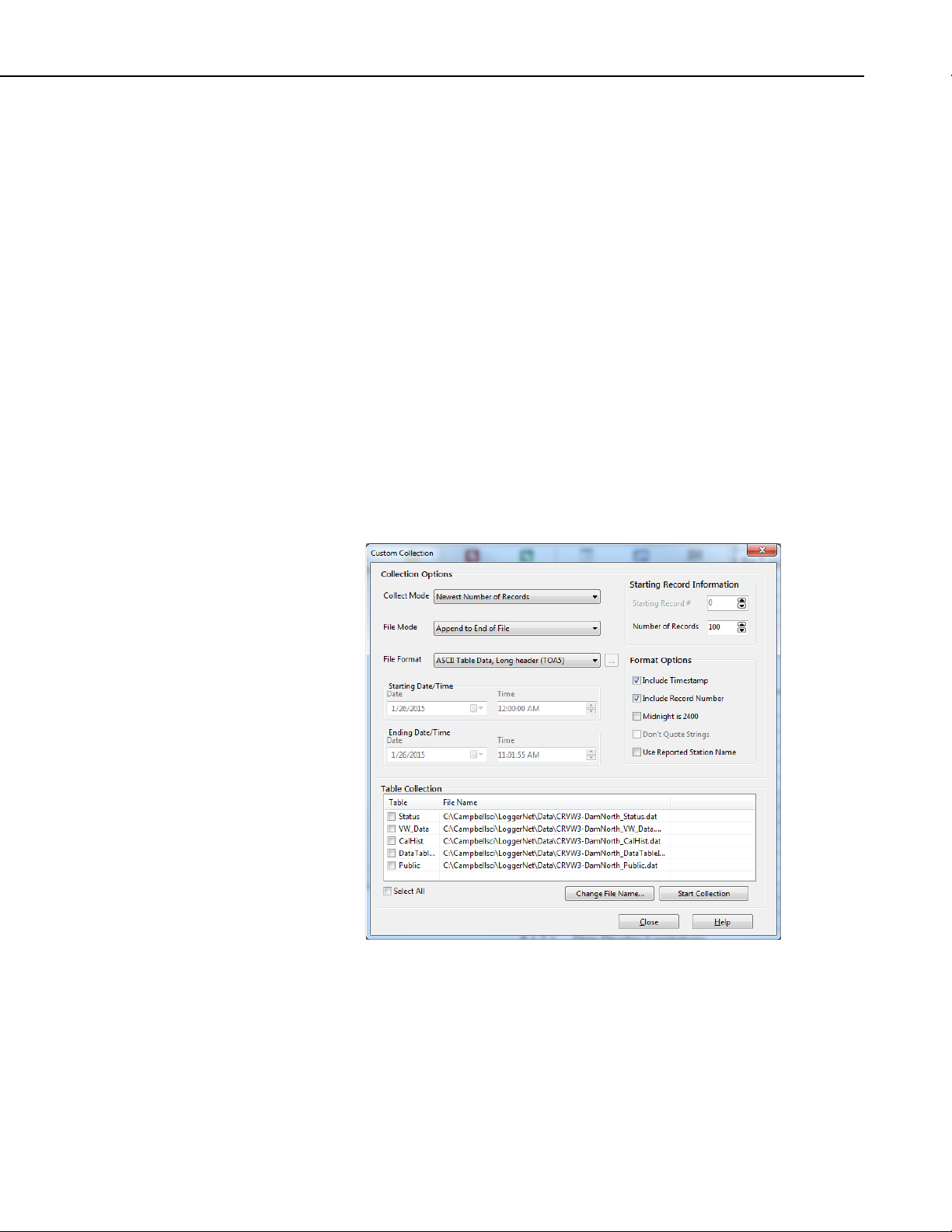
CRVW3 3-Channel Vibrating-Wire Datalogger
automatic collection occurs (defined in the SetupScreen). Only those records
are collected from the device that have not been collected already during
previous scheduled collections or previous Collect Now events. The records
collected are placed into LoggerNet’s cached memory location so that Numeric
and Graphical displays, and other client applications (such as RTMC and
LNDB, see Section 11.4.2, Analyzing and Publishing Historical Data) will see
the data and process/display it.
To use the Collect Now feature, simply ensure you are connected to the station,
and press the Collect Now button. Collect Now can also be used from the
Status Monitor.
Use Custom Collect when you want to retrieve data from a station in a manner
that is completely independent from the scheduled collection process.
Different .DAT files are created and will be placed into a separate folder. A
custom collection has no impact on the execution of the automatic collection
schedule. Any records stored on the device may be collected. The cached
memory location of LoggerNet is not updated, so there is no impact on
Numeric or Graphical displays or other client applications.
To use the Custom Collect feature, press the Custom button while connected to
the station of interest in the ConnectScreen. For more information about
custom data collection, see Section 5.1.2.2 of the LoggerNet manual.
11.2.2 Manual Data Collection at the CRVW3 Site
A technician located at a CRVW3 deployment site can use a USB cable to
manually collect data from a CRVW3 using a Windows computer (laptop PC)
running LoggerNet, PC400, or PC200W software.
If you are using LoggerNet on a laptop in the field, make sure that the
particular CRVW3 device has been added to the network map of the laptop’s
instance of LoggerNet (using SetupScreen or EZSetup, see Section 10.7.2,
75
Page 86

CRVW3 3-Channel Vibrating-Wire Datalogger
NOTE
CAUTION
Configuring the Network Map of LoggerNet) and that the connection is set up
as a ComPort that references your USB cable connection. To do so, make sure
the USB driver is installed (see Section 8.1.4, Connecting to the CRVW3).
Once you have LoggerNet setup correctly, open the ConnectScreen and
connect to the device.
Once you are directly connected to the device in the field via USB, follow the
process outlined in Section 11.2.1, Manual Data Collection From the
LoggerNet Station, above to collect data from the CRVW3.
When using PC400 and PC200W, you will need to add the device in the
EZSetup wizard. Ensure that the USB driver creates a ComPort that
references your USB cable connection, and which is specified in EZSetup.
Once you can connect to the CRVW3, then choose the Collect Data tab from
the main screen of PC400 or PC200W. Refer to the PC400 documentation
(Section 4.4) or PC200W on-line help for details about using the Collect Data
tab.
s.campbellsci.com/documents/us/manuals/pc400.pdf
If your CRVW3 device does not have a radio option, you should
make a plan for visiting the site on a regular basis to collect its
data as described in this section. Plan to make a collection visit
before the newly collected data begins overwriting the older data
that needs to be collected (see explanation in Section
Monitoring Automatic Data Collection).
11.1,
11.3 Station Health Monitoring
You should periodically check the health of each CRVW3 station on your
network using LoggerNet.
In the ConnectScreen, you can monitor the Public and Status tables with the
Table Montior (see Section 10.7.3, Connecting to CRV3 Stations). Use the
Station Status button to bring up the Station Status screen. The Summary tab
will show items in red or blue that may require your attention.
You can view the current settings on each CRVW3 device using the
ConnectScreen. Choose the Settings Editor… option from the Datalogger
menu. A Settings screen will appear that works much like DevConfig. You
can view settings for the device.
Before making changes to a remote device with the
Settings screen, review Section 12.1.3, Adjusting Device
Settings.
In order to keep the clocks of your CRVW3 stations synchronized with the
LoggerNet computer station’s clock, consider the use of the Automatic Clock
Set functionality. Use the Clock tab in the SetupScreen to enable a periodic
and automated clock check for each device. Once enabled for a station, if the
clock of the device has deviated more than a specified interval, the clock will
automatically be set back to (synchronized with) the LoggerNet computer’s
clock value. 24-hour or 7-day clock check intervals are typical. In some cases,
it makes sense to perform automated clock checks at a time different from a
76
Page 87

CRVW3 3-Channel Vibrating-Wire Datalogger
NOTE
scheduled collection event to avoid radio traffic congestion issues. A clock
synchronization is recommended (manually or automatically) at least once per
month.
You can use the PakBusGraph application to periodically ping all of the
stations and make sure PakBus discovery and beaconing is working properly.
For a healthy, operating network, you should see an active link to each device
defined in your Network Map. Make sure you have selected the correct
PakBusPort in the PakBusNetwork dropdown (as defined in SetupScreen) to
view your CRVW3 devices.
For CRVW3-RF451 devices and RF451 radio networks, you can use the
RF450 diagnostic cable (pn 20625) on the master radio (base station) to assess
radio link strength as it changes over time. Install and use the software
provided with the cable to do this. Each CRVW3-RF451 can connect directly
to a computer using this cable and the RF DIAG port located on the wiring
panel of the CRVW3-RF451.
If you use the diagnostic cable (pn 20625) to update the radio
firmware of an RF450 or CRVW3-RF451 device, it must be
configured as a Slave, not the Master. When updating a Master
radio, change it to be a Slave first, then load the firmware, and
then change it back to be the Master after the new firmware is
working.
11.4 Processing Collected Data
Once you have data flowing into the LoggerNet station on a regular basis, you
need to evaluate the quality of the data, analyze the data, and then publish and
deliver it to the appropriate data consumers.
11.4.1 Monitoring Data Influx Using Real-time Displays
You can use the Table Monitor, Numeric Displays, and Graphical displays of
the ConnectScreen in LoggerNet to monitor data as it is collected by
LoggerNet. This works for data collected via automatic collection or via
Collect Now. Once connected, use the Table Monitor dropdown to select one
of the CRVW3 tables for display. Use the Num Display button to open and
configure a numeric display monitor. This allows data from more than one
table to be displayed. Use the Graphs button to display data graphically with
some time history over the width of the display. For more information about
using the Numeric and Graphical displays in the ConnectScreen, refer to the
LoggerNet manual Section 5.1.
You can also use the RTMC (included with LoggerNet) and RTMC Pro
(purchased separately) products to create customized screens for monitoring
data as it is collected. See Section 5.2 of the LoggerNet manual for more
details.
11.4.2 Analyzing and Publishing Historical Data
Once data has been collected by LoggerNet into .DAT files, it is referred to as
Historical data. You will want to review, analyze, examine, and publish data
that has been collected from your CRVW3 stations.
77
Page 88

CRVW3 3-Channel Vibrating-Wire Datalogger
The View Pro application is provided within LoggerNet for viewing and
graphing historical data stored in .DAT files. When you perform a Collect
Now or Custom Collect operation, a screen appears which allows you to open
and display the affected .DAT file within the View Pro application. Press the
View File button in the Data Collection Results Screen. It is also possible to
start the View Pro application from the LoggerNet toolbar and then browse to
and open any .DAT file available on the computer. You can look up the
location of various .DAT files by looking at the Data Files tab for each
CRVW3 in the SetupScreen application. For more information about using
View Pro, refer to Section 8.1 of the LoggerNet manual.
78
Another option available for storing data as it is collected from devices is the
LNDB add-on program (LoggerNet Database software). The LNDB product is
purchased separately from LoggerNet, but it does require a LoggerNet
installation to operate. Once installed and running, LNDB monitors the data
that is collected within LoggerNet and stores it into a MySQL or SQLServer
database that has been configured by the user. This database can be on the
Page 89

CRVW3 3-Channel Vibrating-Wire Datalogger
same computer that runs LoggerNet or on a different computer accessible from
the LoggerNet computer via TCP/IP.
For more information, refer to the LNDB product website:
www.campbellsci.com/lndb
The RTMC and RTMC Pro products can be used to create screens for
viewing real-time data as it is collected by LoggerNet. However, the RTMC
Pro product can also be used to create customized screens for viewing
historical data that resides in .DAT files or in an LNDB database. Once
screens have been created with this product, they can be viewed using the
RTMC Runtime viewer, or they can be published out as web-enabled sites
using the CSI Web Server product. Refer to these product websites for more
information:
www.campbellsci.com/rtmcpro
www.campbellsci.com/csiwebs
12. Maintenance of CRVW3 Networks
After your CRVW3 stations have been operating for some time, there may be
periodic maintenance tasks that need to be performed. Routine maintenance is
a key activity that helps ensure the healthy and ongoing operation of your
system.
Some of these maintenance tasks can be performed remotely using LoggerNet
and related software tools. For other tasks, a visit to the CRVW3 deployment
site is necessary.
12.1 CRVW3 Maintenance with LoggerNet
See Section 11.3, Station Health Monitoring, for details about how to use
LoggerNet to periodically check the health of a CRVW3 station.
From time to time, Campbell Scientific will release updates to the CRVW3
firmware, and make these available for download from the Campbell Scientific
website. See Appendix A, Updating CRVW3 Firmware, for details about how
to update the CRVW3 firmware, including remote updates made from within
LoggerNet.
If the measurement output of the CRVW3 has been configured for engineering
output and baseline readings are used as part of that calculation, then the
sensors may need to be periodically calibrated using the Calibration Wizard.
See Appendix E, Engineering Output and Calibration, for details about
calibration and using the Calibration Wizard.
12.1.1 Battery Monitoring
The status of the battery on the CRVW3 should be monitored using the Battery
field in the Status table. Voltage levels greater than 12 V indicate that the
charge circuit is active and charging the battery. Levels of 12 V or less
indicate no charging is active. Once battery voltage reaches 10.5 V,
79
Page 90

CRVW3 3-Channel Vibrating-Wire Datalogger
functionality on the device begins to be restricted, and the Low10_5_Count
value will be incremented. Full shutdown of the device occurs at 9.5 V.
When using the –ALK option, the D-cells on the device should be replaced
about once every 12 months. This may be needed more frequently if the
–RF451 radio is used, or if measurements are made more frequently than once
every 15 minutes. When using the –RC option, consider replacement of the
rechargeable battery after several years of use.
12.1.2 Sensor Spectrum Checks
You should periodically verify that the CRVW3 is making proper readings
from its sensors. During installation or during on-site maintenance, this can be
done using the Troubleshoot tab in DevConfig (see Section 8.1.6, Testing the
Measurement Operation of the CRVW3, and Section 8.2.8.2, Validation with
DevConfig). There is a way to make a similar spectrum check on a CRVW3
using LoggerNet and a remote connection (i.e., if the device has a radio
option). The creation of a binary file can be triggered, and then that file can be
retrieved to the LoggerNet computer station using File Control. DevConfig
can then be used to view the spectrum and diagnostic contents associated with
that file. In this way, you can see the spectrum information on a remote
CRVW3 without making a field-visit.
Follow this process to check the spectrum on a remote CRVW3 station:
1. Use ConnectScreen to establish a connection to the CRVW3 station of
interest.
2. Open the Status table in the Table Monitor dropdown.
3. Set the Channel_Diag value to match the channel to be tested (1, 2 or 3).
4. Set the Low Frequency and High Frequency desired (in Hz) for the
measurement using the Begin_Freq_Diag and End_Freq_Diag fields.
5. Set the excitation level for the measurement using Excitation_Opt_Diag.
Use 120 for 12 V, 50 for 5 V and 20 for 2 V excitation.
80
Page 91

CRVW3 3-Channel Vibrating-Wire Datalogger
6. Set the Run_Diag value to 1 to trigger the measurement. Watch and wait
for the value to be set back to zero (0) to indicate that the test measurement
is complete. Ensure Diag_Result_Code is zero (0).
7. Open the File Control screen using the File Control button.
8. Note the Spectrum.bin and TimeSeries.bin files located on the CPU drive.
The date and time on these files should match the time of the test
measurement. (A timestamp of zero on the files indicates that they do not
yet exist, the test has not yet been performed).
9. Select only the file TimeSeries.bin and press the Retrieve… button.
10. Save the file to a known folder location on your LoggerNet computer
station.
11. Open DevConfig, choose CRVW Series for the device, select the Off Line
Analysis tab. Press the Read File button, and browse to the
TimeSeries.bin file.
12. The contents of the file will be processed, and DevConfig will display the
spectrum and time-series information as recorded by your remote CRVW3
81
Page 92
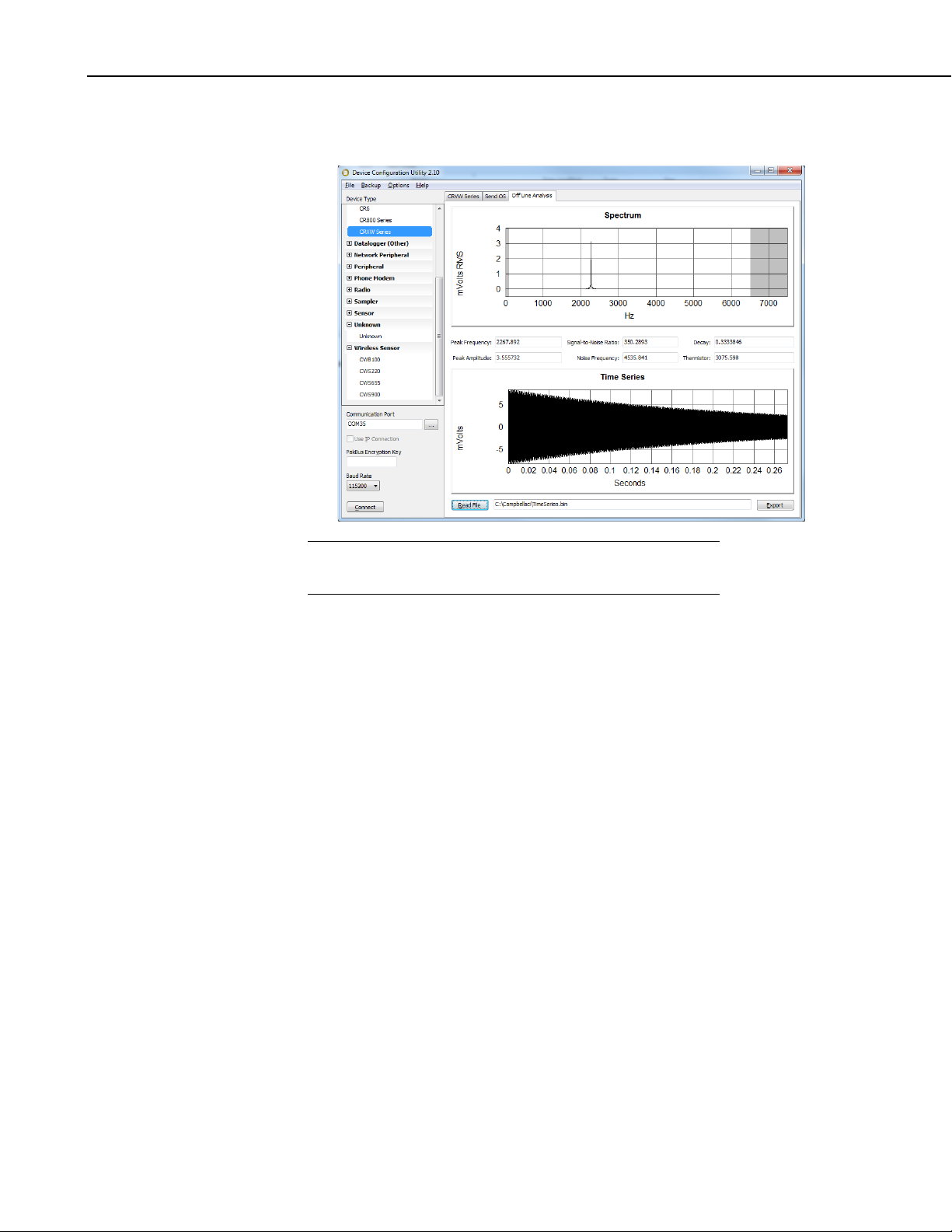
CRVW3 3-Channel Vibrating-Wire Datalogger
NOTE
station. Interpret the information shown in this screen the same way as
when using the Troubleshoot tab.
The Off Line Analysis tab is only available in DevConfig when
not connected to a CRVW3.
Repeat the above process for channels 2 and 3 (individually) if applicable.
Rename the various files as needed to indicate the station and channel that they
represent. It is recommended that some TimeSeries.bin files be captured soon
after the installation of a CRVW3 station so that they can be kept as baseline
references that document how the sensor was operating at the time of
deployment.
12.1.3 Adjusting Device Settings
You can view and change the current settings on each CRVW3 device using
the ConnectScreen. This is possible even when connections are made
remotely to the CRVW3 over radio links, including repeater links. Choose the
Settings Editor… option from the Datalogger menu. A Settings screen will
appear that works much like DevConfig. You can view settings for the device
and change them if necessary. Review the warning below before changing any
settings.
You can also use PakBusGraph to view and edit changes to the device’s
settings. Highlight the device in the main PakBus screen and right-click on the
device, then choose Edit Settings… Make sure you have selected the correct
PakBusPort in the PakBusNetwork dropdown (as defined in SetupScreen) to
view your CRVW3 devices.
82
Make sure you have collected all required data before making a change to the
settings. After you apply changes to a CRVW3’s device settings, the CRVW3
will reset itself to begin measuring with the new settings. Close the Settings
screen since it is no longer connected to the CRVW3. You will need to allow
up to 20 seconds to elapse after pressing Apply before you can expect to
Page 93

CRVW3 3-Channel Vibrating-Wire Datalogger
CAUTION
communicate with the CRVW3 again. You may need to re-connect to the
device in ConnectScreen.
There are risks associated with changing the settings of a
remote CRVW3 using the Settings screen. It is possible to
change the settings on the device in a way that causes it to
stop communicating with LoggerNet. At that point, a fieldvisit is required to restore communications between the
device and LoggerNet. Consider each change carefully and
only apply it once you understand what impact it will have.
Settings that relate to the measurement process are usually
safer to change than settings that relate to radio
communications.
12.2 CRVW3 On-site Maintenance Visits
It is wise to schedule periodic visits to the deployment site of a CRVW3
station. Consider making a visit to inspect each CRVW3 station after the
winter season (in climates where heavy cold-weather precipitation occurs or
where extreme temperatures occur). Heavy-rain events can also affect the
operation of a station in some cases.
The following maintenance operations can be performed after arriving at the
site:
• Check and change the battery or batteries if needed
• Check cable entry points for a good seal
• Wipe moisture off of the lid gasket prior to opening (reduce water
ingress)
• Minimize moisture intrusion through cabling or connectors to the
inside of the enclosure
• Check grounding rod, grounding cable, and connections
• Inspect for loose connections
• Clean solar panel with mild detergent and a clean cloth
• Replace desiccant (pn 4905) and humidity indicator card (pn 28878)
as needed
• Remove any solar barriers (fallen debris, overhead branches, leaves,
etc.)
• Install newer firmware/OS (DevConfig) — Refer to Appendix A,
Updating CRVW3 Firmware
• Look at Sensor spectra using the DevConfig Troubleshoot tab (refer
to Section 8.1.6, Testing the Measurement Operation of the CRVW3,
and Section 8.2.8.2, Validation with DevConfig)
• Watch the LED activity as the device operates to ensure proper
function (see Section 8, Installation of Individual CRVW3 Stations)
You should be aware of the siting and installation issues discussed in Section
8.2, Field Deployment of the CRVW3, and check them for any discrepancies.
83
Page 94

CRVW3 3-Channel Vibrating-Wire Datalogger
You should observe the solar panel operation (–RC option) to ensure it is
charging the battery properly. You can also double-check antenna operation
using a temporary base station radio and a laptop running LoggerNet (see
Section 10, Complex (Large) Radio Networks). Using the Terminal mode of
the CRVW3 from DevConfig can also be used to perform maintenance (see
Appendix B, Terminal Mode from Connect Screen or DevConfig).
13. Troubleshooting CRVW3 Networks
By following the tasks outlined in Section 11, Operation of CRVW3 Networks,
and Section 12, Maintenance of CRVW3 Networks, for operating and
maintaining your network of CRVW3 stations, you can identify problems with
the system when they emerge or very soon after they occur.
The Status Monitor is a key tool for identifying that a problem in the system
exists (see Section 11.1, Monitoring Automatic Data Collection, for guidance
about using Status Monitor). Some common indicators that something is
wrong with a station are:
• Automatic (scheduled) collection is not working as shown by the
Status Monitor or Table Monitor
• You can’t connect to the station in the LoggerNet Connect Screen
• Clock checks (SetupScreen) are not working
• Manual collection doesn’t work (Custom Collect and Collect Now)
• You can’t view the Station Status (Summary and Status Table)
• The station is able to communicate, but the data that is collected from
that station has problems
You should troubleshoot problems as soon as possible after they arise. Some
clues relating to the source of the problem can change (become more obscure)
over time. Small problems can often escalate into larger ones, due to cascading
consequences.
Troubleshooting a part of the system that has never worked is strongly related
to the installation process. Review Sections 7 through 10 as a first step of
investigation in such cases.
When a problem arises in a system area that used to work but has recently
stopped working, the main question to ask is “What changed?” What changed
in the system to cause the station to stop operating? When did the failure
begin? Examine key aspects of the system and its recent maintenance history
to obtain clues about changes made to the system. Sometimes a change to the
system that seems harmless or unrelated turns out to be the cause of the
trouble.
When you begin troubleshooting a system, you do not yet know the source of
the problem. You should suspect all parts of the system (communications,
power, repeaters, base station, software, LoggerNet computer station issues)
until you determine what went wrong. Use the clues given by the problem to
narrow your focus. However, you may need to broaden your focus from time
to time if causes of the problem fail to emerge.
Sometimes the problem is caused by intentional changes to the system,
sometimes it is caused by unintentional changes to the system. Sometimes
problems are caused by acts of nature (lightning strikes, storms, animal
84
Page 95

CRVW3 3-Channel Vibrating-Wire Datalogger
intrusion), and sometimes operational features of the station had problems that
changed gradually and remained undetected until they finally ceased to
function (bad battery, etc.). An on-site camera can be helpful if physical
problems occur with on-site equipment on a regular basis.
It can be helpful to review the key installation sections of this manual (Section
8, Installation of Individual CRVW3 Stations, and Section 10, Complex (Large)
Radio Networks) with a “problem identification” perspective. This can trigger
ideas about things that can be investigated.
You should perform whatever troubleshooting work is possible from the
lab/office before travelling to the field. Once all remote LoggerNet options
have been tried, plan a visit to the field to investigate the station or problem
area directly.
13.1 Troubleshooting Problems Remotely Using LoggerNet
Sometimes you can still communicate with the CRVW3 station, but its
measurements don’t seem to make sense or work only intermittently. In those
cases, you can connect to the station and check the spectrum to see if there is a
sensor problem (sensor cabling, connectivity, operation, noise/interference).
See Section 12.1.2, Sensor Spectrum Checks, for details about how this is done.
Compare the current spectrum with a baseline spectrum saved during
maintenance or installation. A visit to the site may still be required, however
the spectral information may give a clue about what has gone wrong.
PakBusGraph is an excellent tool for troubleshooting stations and how they
communicate with each other. Refer to Section 11.3, Station Health
Monitoring, or Section 6.4 of the LoggerNet manual for more information.
LoggerNet also has a LogTool utility that shows low-level text messages about
how LoggerNet is operating and attempting to connect and interact with
CRVW3 stations. These logs can be captured and sent to your support
representative for evaluation. LoggerNet also has a TroubleShooter utility
that helps to identify communication problems. For more information about
using these tools, refer to Section 6 of the LoggerNet manual.
s.campbellsci.com/documents/us/manuals/LoggerNet.pdf
In an RF451 network of CRVW3 stations, you can perform radio diagnostics
by visiting the base station and using the RF DIAG connector of the
base/master radio. Use the appropriate cable (pn 20625) and run the included
software.
If there is trouble making a connection between LoggerNet and the RF450 base
station, you should use DevConfig to ensure that the baud rate setting of the
RF450 matches the PakBusPort baud rate setting in LoggerNet’s SetupScreen.
If these do not match, connectivity will not occur.
13.2 Troubleshooting Problems by Visiting the CRVW3 Site
Be as prepared as possible when you travel to the field for troubleshooting.
Gather as much information about the problem as possible before arriving.
Bring the same configuration hardware with you to the field as was used during
installation.
85
Page 96

CRVW3 3-Channel Vibrating-Wire Datalogger
Once you have arrived at the site, review physical installation and hardware
configuration issues that are detailed in Section 8.2, Field Deployment of the
CRVW3. Refer to the maintenance items listed in Section 12.2, CRVW3 Onsite Maintenance Visits. Connect to the CRVW3 with a USB cable and
DevConfig then use the DataMonitor tab and Troubleshoot tab to investigate
how the measurements of the sensors are working or not (see Section 8.2.8.2,
Validation with DevConfig). Compare the current spectrum with a baseline
spectrum saved during maintenance (see Section 12.1.2, Sensor Spectrum
Checks).
Refer to Section 10, Complex (Large) Radio Networks, for details that will help
troubleshoot radio connectivity problems. Use a portable base station (RF450
and laptop) to ensure you can communicate with the CRVW3 over its radio. It
may be necessary to visit the base station or a repeater station to fully
investigate radio network problems.
Contact your local Campbell Scientific support representative for additional
help when troubleshooting problems with CRVW3 operation or radio
connectivity.
86
Page 97

NOTE
Appendix A. Updating CRVW3 Firmware
From time to time, Campbell Scientific will release updates to the CRVW3
firmware (also known as the Operating System or OS) which will improve the
operating stability of the product and may introduce minor feature
enhancements. Once published, these are available for download from the
Campbell Scientific website:
www.campbellsci.com/downloads
The version of the OS currently active in the CRVW3 is shown in the Status
table (as OSVersion) which can be viewed in the Data Monitor tab of
DevConfig or in the Table Monitor in the ConnectScreen of LoggerNet. The
version of the OS is also shown in the Main tab on the Settings Editor tab of
DevConfig. A date (OSDate) and signature (OSSignature) are also shown to
help ensure proper installation. Compare your current OS version to that
available on the website to determine whether an update is required. Campbell
support personnel may also provide you with a CRVW3 OS under certain
circumstances.
The OS is packaged as an *.obj file. This file can be sent to the CRVW3 using
DevConfig or LoggerNet. When the CRVW3 receives an *.obj file, the update
of the firmware is triggered automatically.
Any attempt to send a new OS to the CRVW3 will reset the final
storage on the device. You should collect any data needed from
the CRVW3 before making any attempt to update its OS. The
settings of the device will remain intact.
To install the OS with DevConfig:
1. Open DevConfig and choose the CRVW Series for the device.
2. Choose the Send OS tab.
A-1
Page 98
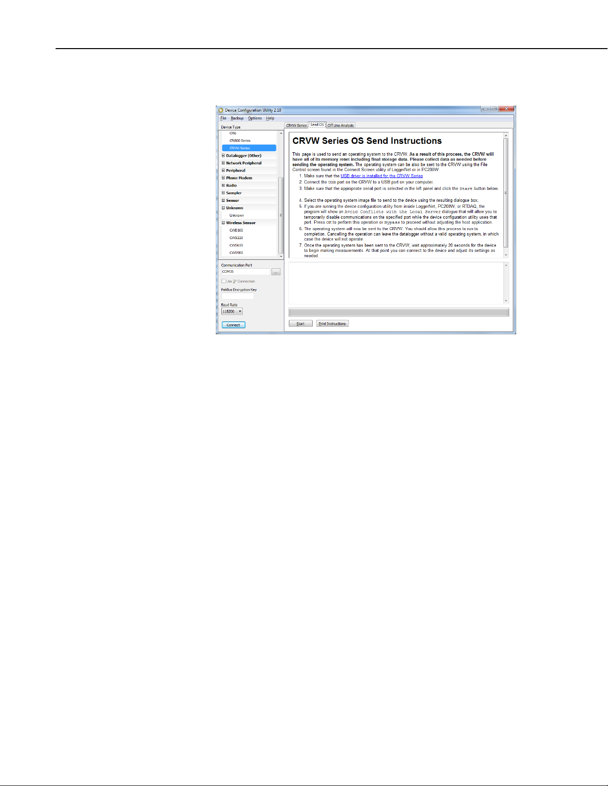
Appendix A. Updating CRVW3 Firmware
3. Follow the instructions shown in this screen, including using the Start
button to browse to the *obj file.
4. The OS file will be read, sent to the CRVW3, and the operating system
will be loaded. A progress bar will be shown during the send process. Do
not remove power from the device during this time.
5. After the OS is sent, a period of about 25 seconds is required to fully load
the OS and restart the device. Watch for both LEDs to flash together
rapidly just before the completion of the update. Do not attempt to
connect to the device during this time.
6. After the load process is complete, connect to the device and confirm in
the Main tab or in the Data Monitor tab that the correct OS was loaded.
To install the OS to a remote CRVW3 using LoggerNet:
1. Ensure all data is collected from the CRVW3. Consider saving the
settings of the device to an *.xml file using the Settings screen (Settings
Editor… from the Datalogger menu of ConnectScreen).
2. Open the ConnectScreen of LoggerNet and connect to the CRVW3
station that will receive the update.
3. Open the File Control screen, press the Send… button.
4. Browse to the *.obj file, select it and press Open.
A-2
5. Carefully review the warning, press OK if no further preparation is needed,
otherwise Cancel.
6. The file is sent over the radio link to the remote CRVW3 and the OS
update occurs automatically.
Page 99

CRVW3 3-Channel Vibrating-Wire Datalogger
CAUTION
7. After the OS is sent, a period of about 25 seconds is required for the
CRVW3 to fully load the OS and restart itself. Do not attempt to connect
to the device during this time.
8. When the load is complete, connect to the device and confirm in the Status
table with the Table Monitor that the proper OS was loaded.
There is a risk that communications may be lost from
LoggerNet to the remote CRVW3 if something goes wrong
during LoggerNet’s OS load process. Ensure you have a
solid radio communications channel with the device before
sending the OS update using LoggerNet and File Control.
You can use File Control in PC400 or PC200W in a similar way to that
described above to send an OS to the CRVW3.
A-3
Page 100

Appendix A. Updating CRVW3 Firmware
A-4
 Loading...