

Page 1

d
w
CR9000X Measurement an
Control System Overvie
Revision: 3/07
Copyright © 1995-2007
Campbell Scientific, Inc.
Page 2

Page 3

CR9000X Overview Table of Contents
Overview..................................................................... OV-1
OV1. Physical Description ......................................................................OV-1
OV1.1 Basic System.........................................................................OV-1
OV1.2 Measurement Modules..........................................................OV-3
OV1.3 Communication Interfaces ....................................................OV-7
OV2. Memory and Programming Concepts............................................OV-8
OV2.1 Memory.................................................................................OV-8
OV2.2 Measurements, Processing, Data Storage..............................OV-8
OV2.3 Data Tables............................................................................OV-9
OV3. PC9000 Application Software .......................................................OV-9
OV3.1 Hardware and Software Requirements..................................OV-9
OV3.2 PC9000 Installation.............................................................OV-10
OV3.3 PC9000 Software Overview................................................OV-10
OV4. Specifications...............................................................................OV-15
i
Page 4

CR9000X Overview Table of Contents
ii
Page 5
Overview
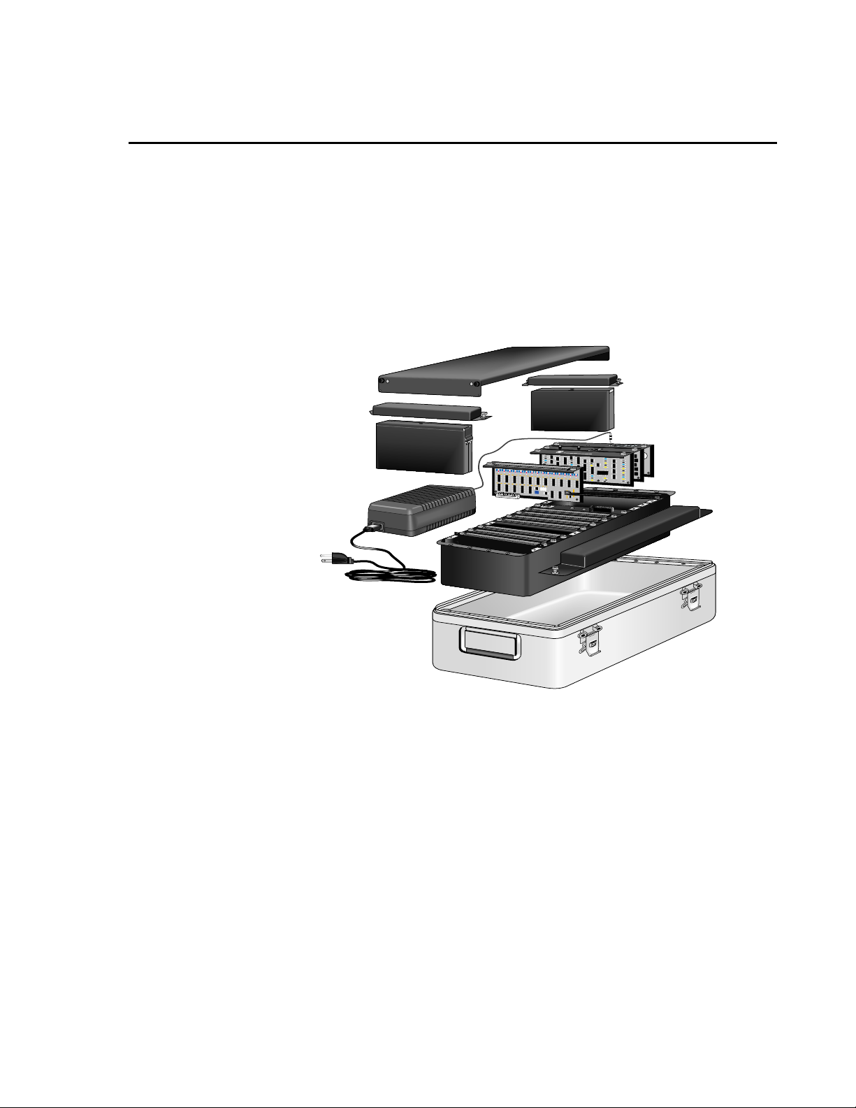
The CR9000X is a modular, multi-processor system that provides precision measurement capabilities
in a rugged, battery-operated package. The system makes measurements at a rate of up to 100 K
samples/second with 16-bit resolution. The CR9000X Base System includes CPU, power supply, and
A/D modules. Up to nine I/O modules are inserted to configure a system for specific applications.
The on-board, BASIC-like programming language includes data processing and analysis routines.
PC9000 Windows
monitoring. LoggerNet software can be used for multiple station applications requiring modem
communications and/or where schedule data collection to a PC is required.
™
Software provides program generation and editing, data retrieval, and realtime
CR9000
R
O
T
P
A
D
A
C
A
FIGURE OV1-1. CR9000X Measurement and Control System
OV1. Physical Description
OV1.1 Basic System
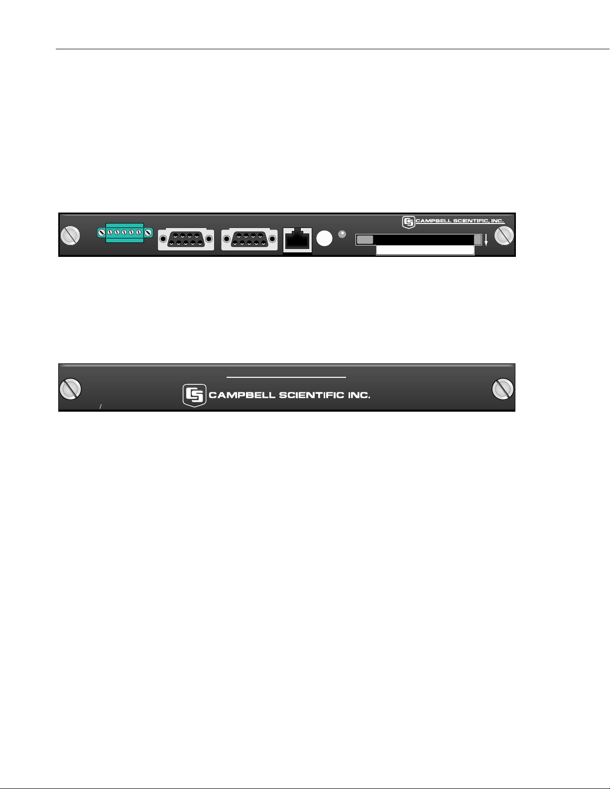
CR9032 CPU Module
The CR9032 CPU Module provides system control, processing, and
communication to a PC via the built-in 10BaseT/100BaseT Ethernet port or the
RS-232 port. The CR9032 also has built-in Serial Device for Measurement
(SDM) terminals and a CSI 9-pin port for communication with Campbell
Scientific peripherals. The SDM 12 volt supply is current limited to 1.85
amps. The main processor is a 180 MHz Hitachi SH-4 microprocessor. The
module has 128 MB SDRAM and 2 MB Flash EEPROM.
OV-1
Page 6
Overview
MEASUREMENTS:
Analog Output Peripheral (AO4)
CANBus Interface Peripheral (CANBUS)
CSAT3 Sonic Anemometer (CSAT3)
DSP4 Display (DSP4)
I/O Port Peripheral (CD16AC)
Interval Timer Peripheral (INT8)
Output Data to PC Card (CardOut)
Serial Input/Output Peripheral (SIO4)
Switch Closure Measurement Peripheral (SW8A)
SDM
CR9032 CPU
+12 G C1 C2 C3
RS-232 CS I/O ETHERNET CARD PC-CARD
FIGURE OV1-2. CR9032
CR9041 A/D and Amplifier Module
The CR9041 A/D and Amplifier Module provides signal conditioning and 16
bit, 100 kHz A/D conversions.
CR9000X
MEASUREMENT & CONTROL SYSTEM
CR9041 A D
FIGURE OV1-3. CR9041
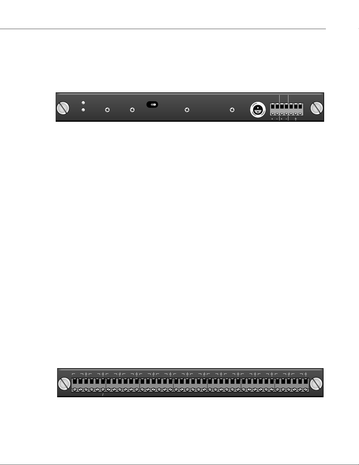
CR9011 Power Supply Module and AC Adapter
The CR9011 Power Supply Module provides regulated power to the CR9000X
from the internal battery modules. It also regulates battery charging from
power supplied by the AC adapter, a DC input, or other external sources. The
AC adapter may be used where AC power is available (100 - 240 volts) to
provide power to the CR9000X and charge its batteries.
LOGAN, UTAH
CONTROL
STATUS
Top of Card Faces Down
MADE IN USA
MADE IN USA
OV-2
The CR9011 has a relay that allows shutting off power under program control.
The Power Up inputs allow an external signal to awaken the CR9000X from a
powered down state (PowerOff, Section 9). When the CR9000X is in this
power off state the On/Off switch is in the on position but the internal relay is
open. The power LED is not lit. If the "<0.5 " input is switched to ground or
if the ">2" input has a voltage greater than 2 volts applied, the CR9000X will
awake, load the program in memory and run. If the "< 0.5" input continues to
be held at ground while the CR9000X is powered on and goes through its 2-5
second initialization sequence, the CR9000X will not run the program in
memory. The CR9011's 12VOUT supply is current limited to 300 mA.
Page 7
MEASUREMENTS:
Battery (voltage and current)
CONTROL:
PowerOff
Overview
POWER
CHARGE
9011 POWER SUPPLY
ON OFF
FIGURE OV1-4. CR9011
OV1.2 Measurement Modules
CR9050 Analog Input Module
The CR9050 Analog Input Module has 14 differential or 28 single-ended
inputs for measuring voltages up to ±5 V. Voltages exceeding ±9 V may cause
errors on other channels. An on-board PRT provides the reference temperature
for thermocouple measurements, while a heavy copper grounding bar and
connectors combine with the case design to reduce temperature gradients for
accurate thermocouple measurements. Resolution on the most sensitive range
is 1.6 µV.
MEASUREMENTS:
Voltage
Differential Voltage (VoltDiff)
Single-Ended Voltage (VoltSE)
MADE IN USA
CHARGE(9-18VDC)
12VOUT POWER UP
>2.0V
<0.8V
SE
1H2
3H4
1
DIF
9050 ANALOG INPUT W RTD
2
L
L
Thermocouple, Differential Voltage (TCDiff) Thermocouple, Single-Ended
Voltage (TCSE)
Bridge measurements (also require CR9060 Excitation Module)
Full Bridge (BrFull)
6 Wire Full Bridge (BrFull6W)
Half Bridge (BrHalf)
3 Wire Half Bridge (BrHalf3W)
4 Wire Half Bridge (BrHalf4W)
Module Temperature (ModuleTemp)
6
8
10
12
14
16
18
20
22
24
26
5
7
9
11
13
15
17
19
21
23
3
4
5
6
7
8
9
10
L
L
L
L
L
L
H
H
H
H
H
H
L
H
H
11
L
L
H
25
12
13
L
H
H
28
27
14
L
L
H
MADE IN USA
FIGURE OV1-5. CR9050
OV-3
Page 8
Overview
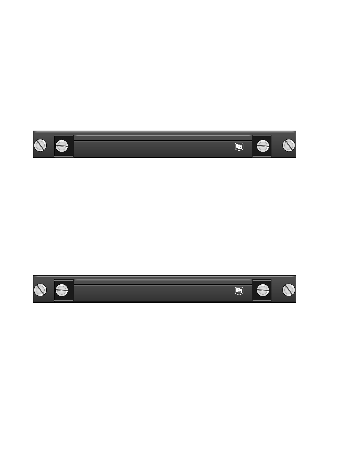
CR9051E Fault Protected 5 V Analog Input Module
The number of channels and measurements are the same as for the CR9050
Analog Input Module. Each input channel is fault-protected so as to permit
over-voltages between +50 V and –40 V without corruption of measurements
on other input channels. All the CR9051E input channels become open
switches when the CR9000X is powered off. The CR9051E is recommended
over the CR9050E for applications where fault voltages beyond ±9 V could
come in contact with the inputs, or when the CR9000X could be powered off
while still connected to sensors that have power applied to them. The
CR9051E supports the same instruction set as the CR9050.
CR9050EC
CR9051E FAULT MADE IN USA
5V ANALOG INPUT CONNECTOR FOR CR9050E OR CR9051E MADE IN USA
FIGURE OV1-6. CR9051E
CR9052DC Anti-Alias Filter Module with DC Excitation
The CR9052DC is a high-performance anti-alias filter module that extends the
capability of the CR9000X Measurement and Control System. The module
includes six anti-aliased analog measurement channels with differential input
ranges from ±20 mV to ±5 V. Each input channel has current and voltage
excitation options. Measurement rates up to 50 kHz per channel are possible.
MEASUREMENTS:
VoltFilt
FFTFilt
CR9052EC
CR9052DC MADE IN USA
FILTER MODULE CONNECTOR DC EXCITATION MADE IN USA
FIGURE OV1-7. CR9052DC
CR9052IEPE Anti-Alias Filter Module with DC Excitation
The The CR9052IEPE module allows direct connection of Internal Electronics
Piezo-Electric (IEPE) accelerometers and microphones to CR9000- or
CR9000X-series dataloggers. Each CR9052IEPE includes six channels. Each
channel has a BNC connector, an open circuit indicator LED, and a short
circuit indicator LED which can indicate if the channel is over-or under-driven.
Each channel has a built-in constant current source which is software
programmable to 0, 2, 4, or 6 mA.
OV-4
Page 9

MEASUREMENTS:
VoltFilt
FFTFilt
Overview
CR9052IEPE
SHORT
OPEN
CH 1
SHORT
OPEN
CH 2
SHORT
OPEN
FIGURE OV1-8. CR9052IEPE
CR9058E Isolation Module
The CR9058E is a 10-channel, differential input isolation module. Each
channel has a 24-bit A/D converter which supplies input isolation for up to ±60
V continuous common mode voltage conditions. The full-scale ranges
available are ±60 V, ±20 V, and ±2 V with a resolution to 2 µVolts. Due to its
superb signal to noise ratio, and good resolution, an accurate thermocouple
measurement can be made on the 2 Volt range code. An on-board
programmable DSP provides digital filtering.
MEASUREMENTS:
VoltDiff
TCDiff
CH 3
SHORT
OPEN
CH 4
SHORT
OPEN
CH 5
SHORT
OPEN
CH 6
MADE IN USA
CR9058EC
CR9058E 60V ISOLATED ANALOG INPUT MODULE W/RTD MADE IN USA
60V ISOLATED ANALOG INPUT CONNECTOR FOR CR9058E MADE IN USA
FIGURE OV1-9. CR9058E
CR9055 50-Volt Analog Input Module
The CR9055 50-Volt Analog Input Module has 14 differential or 28 singleended inputs for measuring voltages up to ±50 V. Resolution on the most
sensitive range is 16 µV. The CR9055 has a common mode range of ±50 V.
MEASUREMENTS:
Voltage
Differential Voltage (VoltDiff)
Single-Ended Voltage (VoltSE)
OV-5
Page 10

Overview
SE
1H2
DIF
Normally thermocouple measurements would be made on the CR9050 Analog
Input Module (±5 Volt) because of its greater resolution, however they can be
made on the CR9055 if the ±50 V common mode range is necessary.
Thermocouple, Differential Voltage (TCDiff)
Thermocouple, Single-Ended Voltage (TCDiff)
3H4
1
2
L
6
8
10
12
14
16
18
20
22
24
26
5
7
9
11
13
15
17
19
21
23
3
4
5
6
7
8
9
10
L
L
L
L
L
L
L
H
H
H
H
H
H
L
H
H
11
L
L
H
25
12
13
L
H
H
28
27
14
L
L
H
9055 50V ANALOG INPUT
FIGURE OV1-10. CR9055
CR9060 Excitation Module
The CR9060 Excitation Module has six continuous analog outputs with
individual digital-to-analog converters for PID Algorithm, waveform
generation, and excitation for bridge measurements. Ten switched excitation
channels provide precision voltages for bridge measurements. Each analog
output will provide up to 50 mA between ±5 V. Also includes eight digital
control outputs (0 V low, 5 V high).
MEASUREMENTS:
Excite
PortSet
Full Bridge (BrFull)
6 Wire Full Bridge (BrFull6w)
Half Bridge (BrHalf)
3 Wire Half Bridge (BrHalf3W)
4 Wire Half Bridge (BrHalf4W)
1 2 3 4 5 6 7 8 9 10 11 12 13 14 15 16 1 3 6 82457
MADE IN USA
9060 EXCITATION C.A.O. SWITCHED EXCITATION DIGITAL CONTROL OUTPUT
FIGURE OV1-11. CR9060
CR9070 Counter - Timer / Digital I/O Module — Obsolete
Features 12 channels capable of high-level
(5 V square wave) pulse counting at frequencies up to 5 MHz. Four channels
can also count switch closures; the other eight can count low-level A/C signals.
In addition, there are 16 independent digital I/O channels for digital control,
communications, and triggering.
OV-6
MADE
IN USA
Page 11

MEASUREMENTS:
Count Pulses or Frequency (PulseCount)
Read State of I/O Channels (ReadI/O)
Write to I/O Channels (WriteI/O)
Overview
3 6 11 14
1 2
45 78 9 10 12 13 15 16 1 2 3 4 5 6 7 8 9 10 11 12
9070 COUNTER & DIGITAL I O
DIGITAL I/O
FIGURE OV1-12. 9070
CR9071E Counter and Digital I/O Module
Features 12 channels capable of high-level (5 V square wave) pulse counting at
frequencies up to 1 MHz. The pulse channels can also do interval timing
measurements with 40 ηs resolution. Four channels can also count switch
closures; the other eight can count low-level A/C signals. In addition, there are
16 independent digital I/O channels for digital control, communications, and
triggering.
MEASUREMENTS:
Count Pulses or Frequency (PulseCount)
Read State of I/O Channels (ReadI/O)
Write to I/O Channels (WriteI/O)
Interval and Timing Measurements (TimerI/O)
LOW LEVEL AC SWITCH CLOSURRE
MADE IN USA
CR9071EC
CR9071E COUNTER MADE IN USA
COUNTER & DIGITAL I/O MADE IN USA
FIGURE OV1-13. CR9071E
OV1.3 Communication Interfaces
The CR900X's CPU module (CR9032) has built-in RS-232 and Ethernet ports,
thus eliminating the need for expensive external communication interfaces.
Any terminal emulator program can be used to set up the CR9000X's IP
address parameters. Hyper Terminal is an example of an available terminal
emulator. The port settings should be:
Bits per Second: 115,200
Data bits: 8
Parity: None
Stop bits: 1
Flow control: Hardware
OV-7
Page 12

Overview
PC9000's Terminal Mode can also be used. Set the Comm window to your
computer’s Comm port and set the baud rate to 115200. With a serial cable
hooked between your PC's and CR9000X's RS-232 ports, press the test button
to ensure that you have established communications. Close the Comm window
and open PC9000's terminal emulator (Tools/Diagnostics/Terminal Mode).
Click in the Low Level I/O box. Press enter a few times until a CR9000>
prompt is returned. Press C and enter. The IP port configuration options will
be shown. See Sections QS1.5 and QS1.6 for additional information about
setting up the IP Port for the CR9000X and for your computer.
OV2. Memory and Programming Concepts
OV2.1 Memory
The CR9032 CPU Module in the CR9000X base system has 128 MB SDRAM
and 2 MB Flash EEPROM. The operating system, user program listing(s), and
calibration files are stored in the flash EEPROM. When the CR9000X is
powered up, the operating system, the compiled program, and any calibration
files are uploaded into SDRAM. The size of available memory may be seen in
the status file. Additional data storage is available through the use of a
PCMCIA memory card in the built-in card slot.
OV2.2 Measurements, Processing, Data Storage
The CR9000X divides a program into two tasks. The measurement task
manipulates the measurement and control hardware on a rigidly timed
sequence. The processing task processes and stores the resulting
measurements and makes the decisions to actuate controls.
The measurement task stores raw Analog to Digital Converter (ADC) data
directly into memory. As soon as the data from a scan is in memory, the
processing task starts. There are at least two buffers allocated for this raw
ADC data (more under program control), thus the buffer from one scan can be
processed while the measurement task is filling another.
When a program is compiled, the measurement tasks are separated from the
processing tasks. When the program runs, the measurement tasks are
performed at a precise rate, ensuring that the measurement timing is exact and
invariant.
OV-8
Page 13

Processing Task: Measurement Task:
Digital I/O task
Read and writes to ports and counters on CR9071
(ReadIO, WriteIO, TimerIO)
Processes measurements
Determines controls (port states) to set next scan
Stores data
Analog measurement and excitation sequence and
timing
Sets ports on 9060 Excitation Module (SetPort)
Sends interrupt to Processor task that reads and sets
ports/counters.
Polls CR9052 and CR9058 for Data
OV2.3 Data Tables
The CR9000X can store individual measurements or it may use its extensive
processing capabilities to calculate averages, maxima, minima, histograms,
FFTs, etc., on periodic or conditional intervals. Data are stored in tables such
as listed in Table OV2-1. The values to output are selected when running the
program generator or when writing a datalogger program directly.
Table OV2-1. Typical Data Table
Overview
TOA4 StnName Temp
TIMESTAMP RECORD RefTemp_Avg TC_Avg(1) TC_Avg(2) TC_Avg(3) TC_Avg(4) TC_Avg(5) TC_Avg(6)
TS RN DegC DegC DegC degC degC degC degC
Avg Avg Avg Avg Avg Avg Avg
2004-02-16 15:15:04.61 278822 31.08 24.23 25.12 26.8 24.14 24.47 23.76
2004-02-16 15:15:04.62 278823 31.07 24.23 25.13 26.82 24.15 24.45 23.8
2004-02-16 15:15:04.63 278824 31.07 24.2 25.09 26.8 24.11 24.45 23.75
2004-02-16 15:15:04.64 278825 31.07 24.21 25.1 26.77 24.13 24.39 23.76
OV3. PC9000 Application Software
PC9000 is a Windows™ application for use with the CR9000X. The software
supports CR9000X program generation, real-time display of datalogger
measurements, graphing, and retrieval of data files.
OV3.1 Hardware and Software Requirements
The following computer resources are recommended:
• IBM PC, portable or desktop
• 64 MB RAM
• VGA monitor
• Windows 2000, Windows XP, Windows NT, or Windows 4.0
• 60 Meg of hard drive space for software
• 400 Meg of hard drive space for data
• RS-232 serial port, a 10BaseT or 100BaseT Ethernet port
The following computer resources are recommended:
• 128 MB RAM
• 233 MHz 486 or faster
• Mouse
OV-9
Page 14

Overview
OV3.2 PC9000 Installation
OV3.3 PC9000 Software Overview
To install the PC9000 software:
• Start Microsoft Windows 2000, NT, or XP
• Insert CD
• From the Program Manager, select F
• Type (disk drive):\setup and press Enter , e.g., a:\setup<Enter>
• The setup routine will prompt for disk 2
You may use the default directory of PC9000 or install the software in a
different directory. The directory will be created for you.
To abort the installation, type Ctrl-C or Break at any time.
This overview points out the main PC9000 functions and where to find them.
PC9000 has extensive on-line help to guide the user in its operation. Install
PC9000 to get the details. A CR9000X is not necessary to try out the
programming and real-time display options; the demo uses canned data for
viewing. Without a CR9000X, there are no communications with the
datalogger; operations such as downloading programs and retrieving data will
not function.
ile menu and choose Run
Figures OV3-1 and OV3-2 show the main PC9000 menus. The primary
functions of PC9000 are accessed from the File, Comm, Realtime, and
Analysis selections on the main menu (Figure OV3-1).
OV-10
Page 15

Overview
File Edit Realtime Analysis Tools Collect Display Windows Help
Display Data Graph 1 . . .
Display Data Graph 2 . . .
ID2000 . . . Ctrl + I
Field Monitor . . .
Virtual Meter . . .
Virtual O'Scope . . .
X-Y Plotter . . .
Histogram . . .
Fast Fourier Transform . . .
Get/Set Variable . . .
Data Retrieval . . .
Scheduled Data Retrieval . . .
CommLink
Select Series Linked Station . . .
Select Parallel Linked Station . . .
Logger Clock . . .
Logger Status . . .
Download . . .
Logger Files . . .
Diagnostics
Display Data in Tables Collected From CR9000.
Graphing requires no special processing of the
data and provides rapid feedback to the operator.
Realtime Display
& Graphing
Collect data from CR9000
PC to CR9000
communications.
Program Generator
Open Program File . . .
Open Wiring File . . .
Open Data Table Info File . . .
Open Data File . . .
Convert Binary to ASCII File . . .
Print . . .
Printer Setup . . .
DOS Shell . . .
File Manager . . .
Explorer . . .
Exit PC9000
Menu-driven Program Generation.
Direct Editing of Program
View/Edit Wiring Diagram & DataTable
Information (Created by Program Generator)
View Data Collected from CR9000
OV3-1. PC9000 Primary Functions
OV-11
Page 16

Overview
y
A
A
A
A
File Edit RealtimeAnalysis Tools Collect Displa
Undo Ctrl + Z
Date & Time
Select All
Cut Ctrl + X
Copy Ctrl + C
Paste Ctrl + V
Delete
Wrap Text Ctrl + W
Go To Line . . .
Find Ctrl + F
Replace Ctrl + R
Colors . . .
Fonts . . .
Defaults . . .
Editing Options for
ctive Windows
Change fonts
and/or Colors for
OV3-2. PC9000 Editing, Help, and User Preferences
Windows Help
ctive Windows.
Tile Horizontal . . .
Tile Vertical . . .
Cascade . . .
rrange Icons . . .
List of Windows
PC9000 Help Contents . . .
Search PC9000 Help . . .
CRBasic Help Contents . . .
Search CRBasic Help . . .
Obtaining Technical Support . . .
bout PC9000 . . .
Software Versions . . .
File
Program Generator
Guides the user through a series of menus to configure the measurement types:
thermocouple, voltage, bridge, pulse counting, frequency, and others. Creates
a CR9000X program, wiring diagram, output table, description, and
configuration file.
Program Editor
Create programs directly or edit those created by the program generator or
retrieved from the CR9000X. Provides context-sensitive help for the
CR9000X's BASIC-like language.
OV-12
Page 17

RealTime
Overview
Alarms List
Allows the display of up to 20 fields from a single data table. Two alarm
conditions can be created for each field by double clicking the left mouse
button while the cursor is held over the field number. After the alarm
parameters are set-up, they can be saved to and subsequently loaded from an
.alm file. The .alm file can be edited using the program editor.
Field Monitor
Allows the display of up to three different tables at a time. Each table module
may display any of the available fields from any of the available tables.
Virtual Meter
Allows the display of up to five different meters at a time. Each meter may
display any of the available fields from any of the available tables. Each meter
may be independently ranged and scaled as desired. In addition, each meter
may have two independent alarms that are visual and/or audible as desired.
Each meter may be displayed as a vertical or horizontal bar graph or as an
analog gauge. If Cal-On-Site is selected from the Program Generator, each
meter can provide access to the sensor calibration facility.
Trend Monitor
Allows the display of up to 20 different traces on a single trend or strip chart.
Each trace may display any of the available fields from any of the available
tables. You can invoke multiple iterations of the Trend Chart window for
viewing additional variable traces.
Virtual Oscilloscope
Allows the display of up to 20 different traces on a single scope. Each trace
may display any of the available fields from any of the available tables. You
can invoke multiple iterations of the Virtual O’Scope window for viewing
additional variable traces.
X-Y Plotter
Allows the plotting of 20 different fields against one field from the same table
in an X-Y configuration. You can invoke multiple iterations of the XY Plot
window.
Spatial Plot
Allows the display of values from multiple fields in a Trend plot. Useful for
displaying data from various sensors in a histogram format. Can also be used
to pick a selection of bins from a histogram or FFT to display. You can invoke
multiple iterations of the Spatial Plot window.
Basic 2-D Histogram
Allows the display of two-dimensional histograms in real-time. You can
invoke multiple iterations of the Histogram window. An understanding of the
Histogram instruction for the data logger is required to make use of this
window.
OV-13
Page 18

Overview
Basic 3-D Histogram
Allows the display of histograms in a real-time 3D format. The 3rd dimension
is based on the record number. You can set the number of histogram records
that you wish to monitor in a single histogram graph.
Rainflow Histogram
Allows the display of RainFlow Histograms in real-time. An understanding of
the Rainflow Histogram instruction for the data logger is required to make use
of this window. You can invoke multiple iterations of the Histogram window.
Level Crossing Histogram
Allows the display of Level Crossing Histograms in real-time. An
understanding of the LevelCrossing Histogram instruction for the data logger
is required to make use of this window. You can invoke multiple iterations of
the Histogram window.
2-D Fast Fourier Transform
Allows the display of FFT's in a 2 dimensional real-time format. An
understanding of the FFT instruction for the datalogger is required to make use
of this window.
3-D Fast Fourier Transform
Allows the display of FFT's in a 3 dimensional real-time format. The third
dimension is based on the record number. You can set the number of FFT
records that you wish to monitor in a single plot.
Analysis
Tools
Collect
Options
Data Graphing
Displays up to 16 fields simultaneously as strip charts or two multi-charts with
up to 8 traces each. Includes 2D/3D bars, line, log/linear, area, and scatter.
Line statistics available for max/min, best fit, mean, and standard deviation.
Handles files of unlimited size. Historical graphing requires no special
processing of the data and provides rapid feedback to the operator.
Control and Communications
Supports PC to CR9000X communications: clock read/set, status read,
program download, and program retrieval.
Data Collection
Collect data from CR9000X data tables.
PC9000 Setup Options
Configure the font and color scheme in an active window.
OV-14
Page 19

Windows
CR9032 CPU MODULE
PROCESSORS: 180 MHz Hitachi SH-4
MEMORY: 128 Mbytes of internal SDRAM for program
and data storage. Expanded data storage with
PCMCIA type I, type II or type III cards.
SERIAL INTERFACES: RS-232
9-pin interface for computer or modem. CS I/O
9-pin interface for CSI peripherals and SDM
devices.
ETHERNET INTERFACE: 10baseT/100baseT port for
communications over a local network or the
Internet.
CR9011 POWER SUPPLY MODULE
VOLTAGE: 9.6 to 18 Vdc
TYPICAL CURRENT DRAIN: Base system with no
modules is 500 mA active; 300 mA standby.
Current drain of individual I/O modules varies.
Refer to specifications for each I/O module for
specific values. Power supply module can place
the system in standby mode by shutting off power
to the rest of the modules.
DC CHARGING: 9.6 to 18 Vdc input charges internal
batteries at up to 2 A rate. Charging circuit
includes temperature compensation.
INTERNAL BATTERIES: Sealed rechargeable with
14 Ahr (7 Ahr for the CR9000XC) capacity per
charge.
EXTERNAL BATTERIES: External 12 V batteries can
be connected.
CR9041 A/D and AMPLIFIER MODULE
A/D Conversions: 16-bit, 100 kHz
TRANSIENT PROTECTION
All analog and digital inputs and outputs use gas
discharge tubes and transient filters to protect against
high-voltage transients. Digital I/Os also have overvoltage protection clamping.
PHYSICAL
Size
LAB ENCLOSURE: 15.75"L x 9.75"W x 8"D
(40 x 24.8 x 20.3 cm)
FIBERGLASS
ENCLOSURE: 18"L x 13.5"W x 9"D
(45.7 x 34.3 x 22.9 cm)
CR9000XC: 10"L x 11"W X 9"D
(25.4 x 27.9 x 22.9 cm)
Weight
LAB ENCLOSURE: 30 lbs including modules
(13.6 kg)
FIBERGLASS ENCLOSURE: 42 lbs including
modules (19.1 kg)
CR9000XC: 27 lbs including modules (12.3 kg)
REPLACEMENT BATTERIES: 6.4 lbs (2.9 kg)
ADDITIONAL MODULES: 1 lb each (0.5 kg)
WARRANTY
Three years against defects in materials and
workmanship.
General CR9000X & CR9000XC Specifications
We recommend that you confirm system
configuration and critical specifications with
Campbell Scientific before purchase.
Electrical specifications are valid over a -25° to +50°C range unless otherwise specified; testing over -40° to
+70°C available as an option, excluding batteries. Non-condensing environment is required. To maintain specifications, Campbell Scientific recommends recalibrating dataloggers every two years.
C9000 Setup Options
Size and arrange windows. Select window to bring to the for-ground. Save
Window setup options to file.
Help
C9000 Help Files
On-line help for PC9000 software.
OV4. Specifications
Overview
OV-15
Page 20

Overview
CR9050(E) and CR9051E ANALOG
INPUT MODULE with RTD
INPUT CHANNELS PER MODULE: 14 differential
or 28 single-ended.
RANGE AND RESOLUTION:
Max
Input Resolution Input Sample
Range (1 A/D count) Noise Rates
(mV) (µV) (µV RMS) (kHz)
±5000 158.0 105 100
±1000 32.0 35 100
±200 6.3 7 50
±50 1.6 4 50
Input
Range Input Noise
(µV RMS)
(mV)
CR9050(E) CR9051E
±5000 105 130
±1000 35 35
±200 7 7
±50 4 4
Note: Measurement averaging provides lower
noise and better resolution.
ACCURACY OF VOLTAGE MEASUREMENTS:
Single-Ended & Differential:
±(0.07% of reading + 4 A/D counts) -25° to +50°C
±(0.14% of reading + 4 A/D counts) -40° to +70°C
Dual Differential:
(two measurements with input polarity reversed)
±(0.07% of reading + 1 A/D count) -25° to +50°C
±(0.14% of reading + 1 A/D count) -40° to +70°C
COMMON MODE RANGE: ±5 V
DC COMMON MODE REJECTION: >120 dB
INPUT RESISTANCE: 2.5 gigaohms typical
MAXIMUM INPUT VOLTAGE WITHOUT
DAMAGE: ±20 V CR9050(E), -40 to +50 V CR9051E
TYPICAL CURRENT DRAIN: 25 mA active
Resistance & Conductivity Measurements
(Also requires 9060 Excitation Module)
ACCURACY: ± (0.04% of reading + 2 A/D counts)
limited by accuracy of external bridge
resistors.
MEASUREMENT TYPES: 6-wire and 4-wire full
bridge, 4-wire, 3-wire, and 2-wire half bridge.
Uses excitation reversal to remove thermal
EMF errors.
CR9052DC ANTI-ALIAS FILTER MODULE
Refer to the CR9052DC documentation
CR9055(E) 50 V-ANALOG
INPUT MODULE
INPUT CHANNELS PER MODULE: 14 differential
or 28 single-ended.
RANGE AND RESOLUTION:
Max
Input Resolution Input Sample
Range (1 A/D count) Noise Rates
(V) (µV) (µV RMS) (kHz)
±50 1580 1050 100
±10 320 350 100
±2 63 85 50
±0.5 16 60 50
Note: Measurement averaging provides lower
noise and better resolution.
ACCURACY OF VOLTAGE MEASUREMENTS:
Single-Ended & Differential:
±(0.1% of reading + 4 A/D counts) -25° to +50°C
±(0.2% of reading + 4 A/D counts) -40° to +70°C
Dual Differential:
(two measurements with input polarity reversed)
±(0.1% of reading + 1 A/D count) -25° to +50°C
±(0.2% of reading + 1 A/D counts) -40° to +70°C
COMMON MODE RANGE: ±50 V
DC COMMON MODE REJECTION: >62 dB
INPUT RESISTANCE: 100 kohms typical
MAXIMUM INPUT VOLTAGE WITHOUT
DAMAGE: ±150 V
TYPICAL CURRENT DRAIN: 15 mA active
CR9058E ISOLATION MODULE
INPUT CHANNELS PER MODULE: 10 isolated, differential; each channel has its own isolation ground for
shielded cable connection.
RANGE, RESOLUTION, AND INPUT RESISTANCE:
Input Resolution Resolution Input
Range w/o Averaging w/ Averaging Resistance
(Vdc) (µV) (µV) (kohms)
±2 ±10 ±2 10,000
±20 ±100 ±20 88.9
±60 ±300 ±60 269
ACCURACY: ±0.02% of Full Scale Range over
-40° to +70°C
MINIMUM SCAN TIME PER MODULE:
VoltDiff: 1285 µs (778 samples per second) +
integration time for no input reversal (RevDiff=0);
or 2990 µs (334 samples per second) +
integration time with input reversal (RevDiff=1)
TCDiff (range parameter set to V2C): 2570 µs
(389 samples per second) + integration time for
no input reversal (RevDiff=0); or 4275 µs (233
samples per second) + integration time with input
reversal (RevDiff=1).
MAXIMUM CONTINUOUS VOLTAGE W/O DAMAGE:
Input H or L to ISO Ground to H or L to
Range H to L ISO Ground Systm Ground Systm Ground
(Vdc) (Vdc) (Vdc) (Vdc) (Vdc)
±2 ±208 ±109 ±360 ±469
±20 ±223 ±121 ±360 ±481
±60 ±448 ±233 ±360 ±593
MAXIMUM ESD VOLTAGE ON INPUTS: ±5000V
TYPICAL CURRENT DRAIN: 360 mA
CR9060 EXCITATION MODULE
TYPICAL CURRENT DRAIN:
108 mA quiescent, 125 mA active
Analog Outputs
ANALOG OUTPUTS PER MODULE:
10 switched, 6 continuous
SWITCHED: Provides excitation for resistance
measurements. Only one output can be active at
a time.
CONTINUOUS: All outputs can be active
simultaneously.
RANGE: ±5 V
ACCURACY: ± (0.2% of output ±4 mV)
RESOLUTION: 12-bit A/D (2.4 mV)
OUTPUT CURRENT: ±50 mA
Digital Control Outputs
CONTROL CHANNELS PER MODULE: 8
OUTPUT VOLTAGES (no load):
High: 5.0 V ±0.2 V
Low: < 0.2 V
OUTPUT RESISTANCE: 100 ohms
CR9071E COUNTER & DIGITAL
I/O MODULE
Counter Channels
COUNTER CHANNELS PER MODULE: 12
MAXIMUM COUNTS PER INTERVAL: 232Maximum
counts per interval will never be reached
because with a maximum input frequency of 1
MHz, the 32-bit counter will go 71.58 minutes
before it rolls over. The maximum CR9000X scan
rate is 1 minute.
SWITCH CLOSURE MODE (4 channels)
Minimum switch closed time: 5 ms
Minimum switch open time: 6 ms
Maximum bounce time: 1 ms open without
being counted
HIGH FREQUENCY MODE (all channels)
Minimum pulse width: 500 ns
Maximum input frequency: 1 MHz
Thresholds: Pulse counted on transition from
below 1.5 V to above 3.5 V
Maximum input voltage: ±20 V
LOW LEVEL AC MODE (8 channels)
Input hysteresis: 10 mV
Minimum ac voltage: 25 mV RMS
Maximum input voltage: ±20 V
Frequency range:
(mV RMS) RANGE (Hz)
25 mV 1 to 10,000
≥50 mV 0.5 to 20,000
TYPICAL CURRENT DRAIN: 35 mA
Digital Inputs/Outputs
I/O CHANNELS PER MODULE: 16
OUTPUT VOLTAGES (no load)
High: 5.0 V ±0.2 V
Low: < 0.2 V
OUTPUT RESISTANCE: 320 ohms
Input State
High: 3.5 to 5 V
Low: -0.5 to 1.2 V
Input Resistance: 100 kOhms
Interval Measurement
I/O CHANNELS:
Resolution is the scan rate
PULSE CHANNELS
Maximum interval: 1 minute
Resolution: ±40 ns
`
CR9000X & CR9000XC I/O Module Specifications
Copyright © 2004
Campbell Scientific, Inc.
Printed May 2004
We recommend that you confirm system
configuration and critical specifications with
Campbell Scientific before purchase.
OV-16
Page 21

CR9052DC Specifications
Operating temperature range is -40° to +70°C (specifications valid over this range unless otherwise specified).
Non-condensing environment required. To maintain specifications, yearly recalibrations are recommended.
Inputs
Number of differential
input channels: 6
Programmable anti-aliasing implemented with finite-impulse-response filters
Output sample rate f
Sample ratio f
Top of the pass band f
Bottom of the stop band f
Transition band rolloff f
Sample Ratio f
2.5 f
5 f
10 f
20 f
PASS
SAMPLE
SAMPLE
SAMPLE
SAMPLE
/2.5 f
/5 f
/10 f
/20 f
SAMPLE
SAMPLE/fPASS
PASS
STOP
PASS/fSTOP
f
STOP
/2.01 1.24
SAMPLE
/3.37 1.48
SAMPLE
/5.08 1.97
SAMPLE
/6.81 2.94
SAMPLE
programmable: 50 ksamples s-1to 5 samples s
programmable: 2.5, 5, 10, or 20
f
PASS/fSTOP
Linear phase response: group delay is independent of frequency
Pass band ripple: ≤ 0.01 dB
Stop band attenuation: ≥ 90 dB
Group delay: 36 / f
Channel-to-channel
SAMPLE
sampling simultaneity: ≤ 100 nsec
CR9052 measurement rates
Non-burst: 15 ksamples s
Bursting to PC FLASH card: 50 ksamples s
Bursting to rotating media
PC card 100 ksamples s
Bursting to 8-Msample
buffer on filter module: 300 ksamples s
-1
, aggregate*
-1
, aggregate*
-1
, aggregate*
-1
, aggregate per module**
*The aggregate rate is the sum of the measurement rates on all channels
**The aggregate per module rate is the sum of measurement rates on all channels of a single filter module
Analog Input Full-Scale Dynamic Range
Differential Ranges Noise Performance (f
±5000 mV 50 µV + 600 nV * sqrt (f
±1000 mV 10 µV + 150 nV * sqrt (f
±200 mV 2 µV + 30 nV * sqrt (f
±50 mV 0.5 µV + 12 nV * sqrt (f
±20 mV 0.25 µV + 8 nV * sqrt (f
) 106 dB -70 dB
PASS
) 106 dB -70 dB
PASS
) 106 dB -83 dB
PASS
) 106 dB -95 dB
PASS
) 103 dB -103 dB
PASS
=10 Hz) CMRR
PASS
CMRR = common-mode rejection ratio = common-mode gain / differential-mode gain.
CMRR specified from dc to 500 Hz.
Gain accuracy: ± 0.03 percent of reading
Offset accuracy: ± 0.03 percent of full-scale input range
Input resistance: 1 x 10
9
Ω
Input time constant: 1 kΩ x 100 pF = 100 nsec
Input offset current: ≤ 35 nA
Common-mode input range: +15 to -5 V
Channel-to-channel crosstalk: ≤ -120 dB
-1
Overview
OV-17
Page 22

Overview
CR9052DC Specifications
(continued)
FFT Spectrum Analyzer
Fourier transforms applied to anti-aliased inputs described above
Number of channels: 6
Time series sample rates: programmable from 50 ksamples s
FFT length: programmable from 32 to 65,536 samples
Real-time spectral throughput
for six channels: 50-kHz or slower, 2048-point or smaller, seamless snapshots
for two channels: 50-kHz or slower, 65536-point or smaller, seamless snapshots
Optional time series windows: Hanning, Hamming, Blackman
Spectrum options: Real and imaginary, Amplitude and phase, Amplitude, Amplitude rms, Power,
Power spectral density, dB
Optional spectral binning to reduce final spectrum length
Linear spectral binning: 2 ≤ m ≤ (FFT_length/2)
where programmable m adjacent bins are combined into a single bin
Logarithmic spectral binning: 1 ≤ n ≤ 12
where exponentially increasing spectral bin width gives 1/n Octave Analyses
-1
to 5 samples s
-1
Excitations
Number of continuous
excitation channels: 6
Programmable
Excitation Levels Compliance Accuracy
10 V 85 mA ± 0.03 percent of setting, -25° to 50° C
5 V 85 mA ± 0.03 percent of setting, -25° to 50° C
10 mA 12 V ± 0.06 percent of setting, -25° to 50° C
± 0.05 percent of setting, -40° to 70° C
± 0.05 percent of setting, -40° to 70° C
± 0.08 percent of setting, -40° to 70° C
General
Over-voltage protection
on all inputs and outputs: + 50 V, -40 V
Current consumption
(at 12 V input): 500 mA + 1.5*[I
Current consumption
for complete CR9000 system: must be less than 4 A
Sensor connections use CR9052EC Easy Connectors for CR9052DC. The Easy Connectors consist of a terminal strip that is
easily disconnected from the CR9052. Customers needing to monitor several locations intermittently have found it useful
to buy several CR9052ECs and simply move the CR9000 and on-board CR9052DC(s) between monitoring locations.
where I
ex
]
ex
is the sum of excitation currents provided by all channels
We recommend that you confirm system
configuration and critical specifications with
Campbell Scientific before purchase.
C opyright © 2000
C am pbell Scientific, Inc.
Printed April 2001
OV-18
Page 23

This is a blank page.
Page 24

Campbell Scientific Companies
Campbell Scientific, Inc. (CSI)
815 West 1800 North
Logan, Utah 84321
UNITED STATES
www.campbellsci.com
info@campbellsci.com
Campbell Scientific Africa Pty. Ltd. (CSAf)
PO Box 2450
Somerset West 7129
SOUTH AFRICA
www.csafrica.co.za
cleroux@csafrica.co.za
Campbell Scientific Australia Pty. Ltd. (CSA)
PO Box 444
Thuringowa Central
QLD 4812 AUSTRALIA
www.campbellsci.com.au
info@campbellsci.com.au
Campbell Scientific do Brazil Ltda. (CSB)
Rua Luisa Crapsi Orsi, 15 Butantã
CEP: 005543-000 São Paulo SP BRAZIL
www.campbellsci.com.br
suporte@campbellsci.com.br
Campbell Scientific Canada Corp. (CSC)
11564 - 149th Street NW
Edmonton, Alberta T5M 1W7
CANADA
www.campbellsci.ca
dataloggers@campbellsci.ca
Campbell Scientific Ltd. (CSL)
Campbell Park
80 Hathern Road
Shepshed, Loughborough LE12 9GX
UNITED KINGDOM
www.campbellsci.co.uk
sales@campbellsci.co.uk
Campbell Scientific Ltd. (France)
Miniparc du Verger - Bat. H
1, rue de Terre Neuve - Les Ulis
91967 COURTABOEUF CEDEX
FRANCE
www.campbellsci.fr
campbell.scientific@wanadoo.fr
Campbell Scientific Spain, S. L.
Psg. Font 14, local 8
08013 Barcelona
SPAIN
www.campbellsci.es
info@campbellsci.es
Please visit www.campbellsci.com to obtain contact information for your local US or International representative.
 Loading...