

Page 1

OPERATOR'S MANUAL
Revision: 7/17
Want to get going? Go to the Quickstart
section.
Copyright © 2000 – 2017
(p. 39)
CR6 Series Dataloggers
Campbell Scientific, Inc.
Page 2

Page 3

3
Warranty
The CR6 Measurement and Control Datalogger is warranted for three (3) years
subject to this limited warranty:
Limited Warranty: Products manufactured by CSI are warranted by CSI to be free
from defects in materials and workmanship under normal use and service for
twelve months from the date of shipment unless otherwise specified in the
corresponding product manual. (Product manuals are available for review online
at www.campbellsci.com.) Products not manufactured by CSI, but that are resold
by CSI, are warranted only to the limits extended by the original manufacturer.
Batteries, fine-wire thermocouples, desiccant, and other consumables have no
warranty. CSI's obligation under this warranty is limited to repairing or replacing
(at CSI's option) defective Products, which shall be the sole and exclusive remedy
under this warranty. The Customer assumes all costs of removing, reinstalling,
and shipping defective Products to CSI. CSI will return such Products by surface
carrier prepaid within the continental United States of America. To all other
locations, CSI will return such Products best way CIP (port of entry) per
Incoterms ® 2010. This warranty shall not apply to any Products which have been
subjected to modification, misuse, neglect, improper service, accidents of nature,
or shipping damage. This warranty is in lieu of all other warranties, expressed or
implied. The warranty for installation services performed by CSI such as
programming to customer specifications, electrical connections to Products
manufactured by CSI, and Product specific training, is part of CSI's product
warranty. CSI EXPRESSLY DISCLAIMS AND EXCLUDES ANY IMPLIED
WARRANTIES OF MERCHANTABILITY OR FITNESS FOR A
PARTICULAR PURPOSE. CSI hereby disclaims, to the fullest extent allowed by
applicable law, any and all warranties and conditions with respect to the Products,
whether express, implied or statutory, other than those expressly provided herein.
Page 4

Page 5

5
Assistance
Products may not be returned without prior authorization. The following contact
information is for US and International customers residing in countries served by
Campbell Scientific, Inc. directly. Affiliate companies handle repairs for
customers within their territories. Please visit www.campbellsci.com to determine
which Campbell Scientific company serves your country.
To obtain a Returned Materials Authorization (RMA), contact CAMPBELL
SCIENTIFIC, INC., phone (435) 227-9000. After a support engineer determines
the nature of the problem, an RMA number will be issued. Please write this
number clearly on the outside of the shipping container. Campbell Scientific's
shipping address is:
CA
MPBELL SCIENTIFIC, INC.
RMA#_____
815 West 1800 North
Logan, Utah 84321-1784
For all returns, the customer must fill out a "Statement of Product Cleanliness and
Decontamination" form and comply with the requirements specified in it. The
form is available from our web site at www.campbellsci.com/repair. A completed
form must be either emailed to repair@campbellsci.com or faxed to
435-227-9106. Campbell Scientific is unable to process any returns until we
receive this form. If the form is not received within three days of product receipt
or is incomplete, the product will be returned to the customer at the customer's
expense. Campbell Scientific reserves the right to refuse service on products that
were exposed to contaminants that may cause health or safety concerns for our
employees.
Page 6

Page 7

7
Precautions
DANGER — MANY HAZARDS ARE ASSOCIATED WITH INSTALLING,
USING, MAINTAINING, AND WORKING ON OR AROUND TRIPODS,
TOWERS, AND ANY ATTACHMENTS TO TRIPODS AND TOWERS SUCH
AS SENSORS, CROSSARMS, ENCLOSURES, ANTENNAS, ETC. FAILURE
TO PROPERLY AND COMPLETELY ASSEMBLE, INSTALL, OPERATE,
USE, AND MAINTAIN TRIPODS, TOWERS, AND ATTACHMENTS, AND
FAILURE TO HEED WARNINGS, INCREASES THE RISK OF DEATH,
ACCIDENT, SERIOUS INJURY, PROPERTY DAMAGE, AND PRODUCT
FAILURE. TAKE ALL REASONABLE PRECAUTIONS TO AVOID THESE
HAZARDS. CHECK WITH YOUR ORGANIZATION'S SAFETY
COORDINATOR (OR POLICY) FOR PROCEDURES AND REQUIRED
PROTECTIVE EQUIPMENT PRIOR TO PERFORMING ANY WORK.
Use tripods, towers, and attachments to tripods and towers only for purposes for
which they are designed. Do not exceed design limits. Be familiar and comply
with all instructions provided in product manuals. Manuals are available at
www.campbellsci.com or by telephoning 435-227-9000 (USA). You are
responsible for conformance with governing codes and regulations, including
safety regulations, and the integrity and location of structures or land to which
towers, tripods, and any attachments are attached. Installation sites should be
evaluated and approved by a qualified engineer. If questions or concerns arise
regarding installation, use, or maintenance of tripods, towers, attachments, or
electrical connections, consult with a licensed and qualified engineer or
electrician.
General
• Prior to performing site or installation work, obtain required approvals
and permits. Comply with all governing structure-height regulations,
such as those of the FAA in the USA.
• Use only qualified personnel for installation, use, and maintenance of
tripods and towers, and any attachments to tripods and towers. The use of
licensed and qualified contractors is highly recommended.
• Read all applicable instructions carefully and understand procedures
thoroughly before beginning work.
• Wear a hardhat and eye protection, and take other appropriate safety
precautions while working on or around tripods and towers.
• Do not climb tripods or towers at any time, and prohibit climbing by
other persons. Take reasonable precautions to secure tripod and tower
sites from trespassers.
• Use only manufacturer recommended parts, materials, and tools.
Page 8

8
Utility and Electrical
• You can be killed or sustain serious bodily injury if the tripod, tower, or
attachments you are installing, constructing, using, or maintaining, or a
tool, stake, or anchor, come in contact with overhead or underground
utility lines.
• Maintain a distance of at least one-and-one-half times structure height, or
20 feet, or the distance required by applicable law, whichever is greater,
between overhead utility lines and the structure (tripod, tower,
attachments, or tools).
• Prior to performing site or installation work, inform all utility companies
and have all underground utilities marked.
• Comply with all electrical codes. Electrical equipment and related
grounding devices should be installed by a licensed and qualified
electrician.
Elevated Work and Weather
• Exercise extreme caution when performing elevated work.
• Use appropriate equipment and safety practices.
• During installation and maintenance, keep tower and tripod sites clear of
un-trained or non-essential personnel. Take precautions to prevent
elevated tools and objects from dropping.
• Do not perform any work in inclement weather, including wind, rain,
snow, lightning, etc.
Maintenance
• Periodically (at least yearly) check for wear and damage, including
corrosion, stress cracks, frayed cables, loose cable clamps, cable
tightness, etc. and take necessary corrective actions.
• Periodically (at least yearly) check electrical ground connections.
WHILE EVERY ATTEMPT IS MADE TO EMBODY THE HIGHEST
DEGREE OF SAFETY IN ALL CAMPBELL SCIENTIFIC PRODUCTS, THE
CUSTOMER ASSUMES ALL RISK FROM ANY INJURY RESULTING
FROM IMPROPER INSTALLATION, USE, OR MAINTENANCE OF
TRIPODS, TOWERS, OR ATTACHMENTS TO TRIPODS AND TOWERS
SUCH AS SENSORS, CROSSARMS, ENCLOSURES, ANTENNAS, ETC.
Page 9

9
Table of Contents
1. Introduction .............................................................. 33
1.1 HELLO ................................................................................................. 33
1.2 Typography ........................................................................................... 34
1.3 Capturing CRBasic Code ...................................................................... 34
2. Precautions .............................................................. 35
3. Initial Inspection ....................................................... 37
4. Quickstart ................................................................. 39
4.1 Sensors — Quickstart ......................................................................... 39
4.2 Datalogger — Quickstart ...................................................................... 40
4.2.1 CR6 Module ................................................................................ 40
4.2.1.1 Wiring Panel — Quickstart................................................ 40
4.3 Power Supplies — Quickstart ................................................................ 41
4.3.1 Internal Battery — Quickstart ..................................................... 42
4.3.2 Internal Voltage Regulator / Battery Charger — Quickstart ....... 42
4.4 Data Retrieval and Comms — Quickstart ............................................ 43
4.5 Datalogger Support Software — Quickstart ......................................... 44
4.6 Tutorial: Measuring a Thermocouple ................................................... 45
4.6.1 What You Will Need ................................................................... 45
4.6.2 Hardware Setup ........................................................................... 45
4.6.2.1 Connect Comms ................................................................ 46
4.6.3 PC200W Software Setup ............................................................. 46
4.6.4 Write CRBasic Program with Short Cut ..................................... 47
4.6.4.1 Procedure: (Short Cut Steps 1 to 5) ................................... 48
4.6.4.2 Procedure: (Short Cut Steps 6 to 7) ................................... 48
4.6.4.3 Procedure: (Short Cut Step 8) ............................................ 49
4.6.4.4 Procedure: (Short Cut Steps 9 to 12) ................................. 50
4.6.4.5 Procedure: (Short Cut Steps 13 to 14) ............................... 50
4.6.5 Send Program and Collect Data .................................................. 51
4.6.5.1 Procedure: (PC200W Step 1)............................................. 51
4.6.5.2 Procedure: (PC200W Steps 2 to 4) .................................... 52
4.6.5.3 Procedure: (PC200W Step 5)............................................. 53
4.6.5.4 Procedure: (PC200W Step 6)............................................. 54
4.6.5.5 Procedure: (PC200W Steps 7 to 10) .................................. 55
4.6.5.6 Procedure: (PC200W Steps 11 to 12) ................................ 56
4.6.5.7 Procedure: (PC200W Steps 13 to 14) ................................ 56
4.7 Data Acquisition Systems — Quickstart .............................................. 57
5. Overview ................................................................... 59
5.1 Datalogger — Overview ....................................................................... 60
5.1.1 Wiring Panel — Overview .......................................................... 61
5.1.1.1 Switched Voltage Output — Overview ............................. 65
5.1.1.2 Voltage and Current Excitation — Overview ................. 66
5.1.1.3 Power Terminals ................................................................ 67
5.1.1.3.1 Power In Terminals ................................................. 67
5.1.1.3.2 Power Out Terminals .............................................. 67
Page 10

Table of Contents
10
5.1.1.4 Communication Ports — Overview ................................... 67
5.1.1.4.1 CS I/O Port .............................................................. 68
5.1.1.4.2 RS-232 Ports ........................................................... 69
5.1.1.4.3 USB Port ................................................................. 69
5.1.1.4.4 Micro SD Card Slot ................................................. 69
5.1.1.4.5 SDI-12 Ports ............................................................ 69
5.1.1.4.6 SDM Port ................................................................ 70
5.1.1.4.7 CPI Port and CDM Devices — Overview ............... 70
5.1.1.4.8 Ethernet Port ............................................................ 70
5.1.1.5 Grounding — Overview .................................................... 70
5.2 Measurements — Overview ................................................................... 71
5.2.1 Time Keeping — Overview ........................................................ 71
5.2.2 Analog Measurements — Overview ........................................... 71
5.2.2.1 Voltage Measurements — Overview ................................. 72
5.2.2.1.1 Single-Ended Measurements — Overview ............. 73
5.2.2.1.2 Differential Measurements — Overview ................ 74
5.2.2.2 Current Measurements — Overview ................................. 75
5.2.2.3 Resistance Measurements — Overview ............................ 75
5.2.2.3.1 Voltage Excitation ................................................... 75
5.2.2.3.2 Current Excitation ................................................... 77
5.2.2.4 Strain Measurements — Overview .................................... 78
5.2.3 Pulse Measurements — Overview .............................................. 78
5.2.3.1 Pulses Measured ................................................................ 78
5.2.3.2 Pulse Input Channels ......................................................... 79
5.2.3.3 Pulse Sensor Wiring .......................................................... 79
5.2.4 Period Averaging — Overview ................................................... 81
5.2.5 Vibrating Wire Measurements — Overview ............................... 81
5.2.5.1 VSPECT Quickstart ........................................................... 82
5.2.6 Reading Smart Sensors — Overview .......................................... 82
5.2.6.1 SDI-12 Sensor Support — Overview ................................ 83
5.2.6.2 RS-232 — Overview ......................................................... 83
5.2.6.3 RS-485 — Overview ......................................................... 84
5.2.7 Field Calibration — Overview .................................................... 84
5.2.8 Cabling Effects — Overview ...................................................... 85
5.2.9 Synchronizing Measurements — Overview ................................ 85
5.2.9.1 Synchronizing Measurements in the CR6 — Overview .... 85
5.2.9.2 Synchronizing Measurements in a Datalogger
Network — Overview ............................................................... 85
5.3 Data Retrieval and Comms — Overview ............................................. 85
5.3.1 Data File Formats in CR6 Memory ............................................. 86
5.3.2 Data Format on Computer ........................................................... 86
5.3.3 Mass-Storage Device................................................................... 86
5.3.4 Memory Card (CRD: Drive) — Overview .................................. 86
5.3.4.1 Comms ............................................................................... 87
5.3.4.2 Direct with Adapter to PC ................................................. 87
5.3.5 Comms Protocols ........................................................................ 87
5.3.5.1 PakBus Comms — Overview ............................................ 87
5.3.6 Alternate Comms Protocols — Overview ................................... 88
5.3.6.1 Modbus — Overview ........................................................ 88
5.3.6.2 DNP3 — Overview ........................................................... 89
5.3.6.3 TCP/IP — Overview.......................................................... 89
5.3.6.4 SPI — Overview ................................................................ 90
5.3.6.5 I2C — Overview ............................................................... 90
5.3.7 Comms Hardware — Overview .................................................. 90
5.3.8 Keyboard/Display — Overview .................................................. 90
Page 11

Table of Contents
11
5.3.8.1 Character Set ..................................................................... 91
5.3.8.2 Custom Menus — Overview ............................................. 91
5.4 Measurement and Control Peripherals — Overview ............................ 92
5.5 Power Supplies — Overview ................................................................ 93
5.5.1 Charging Batteries — Overview ................................................. 93
5.6 CR6 Setup — Overview ....................................................................... 93
5.7 CRBasic Programming — Overview ................................................... 94
5.8 Security — Overview ........................................................................... 94
5.9 Maintenance — Overview .................................................................... 95
5.9.1 Protection from Moisture — Overview....................................... 95
5.9.2 Protection from Voltage Transients — Overview ....................... 95
5.9.3 Factory Calibration — Overview ................................................ 96
5.9.4 Internal Battery — Overview ...................................................... 96
5.10 Datalogger Support Software — Overview ........................................ 97
5.11 PLC Control — Overview .................................................................. 97
5.12 Auto Self-Calibration — Overview .................................................... 99
5.13 Memory — Overview ......................................................................... 99
6. Specifications .......................................................... 101
6.1 Programmable Terminals — Specifications ....................................... 101
6.1.1 Analog Function: Input — Specifications ................................. 101
6.1.1.1 Basic Voltage Measurements — Specifications .............. 102
6.1.1.2 Thermocouple Measurements — Specifications ............. 105
6.1.1.3 Thermistor Measurements — Specifications ................... 106
6.1.1.4 Resistance Measurements — Specifications ................... 106
6.1.1.5 Static Vibrating Wire Measurements — Specifications .. 107
6.1.1.6 Period Average Measurements — Specifications ......... 107
6.1.2 Analog Function: Output — Specifications .............................. 108
6.1.2.1 Voltage and Current Excitation — Specifications ........... 108
6.1.3 Logic Levels — Specifications ................................................. 109
6.1.4 Pulse Counting Function — Specifications ............................... 110
6.1.5 Digital I/O Function: Input — Specifications ........................... 112
6.1.5.1 State — Specifications ..................................................... 112
6.1.5.2 Edge Timing — Specifications ........................................ 113
6.1.5.3 Edge Counting — Specifications ..................................... 113
6.1.5.4 Interrupt — Specifications ............................................... 113
6.1.6 Digital I/O Function: Output — Specifications ........................ 113
6.1.6.1 Control (Switched-Voltage Output) — Specifications .... 114
6.1.6.2 Pulse Width Modulation — Specifications ..................... 114
6.1.7 Digital I/O Function: Communications — Specifications ........ 114
6.2 Dedicated Communication Terminals — Specifications .................... 116
6.2.1 Wi-Fi — Specifications ............................................................. 117
6.3 Communications — Specifications .................................................... 117
6.3.1 Communication Protocols — Specifications ............................ 119
6.3.2 Proven Communication Interfaces — Specifications ................ 121
6.4 Data Retrieval — Specifications ......................................................... 121
6.5 Power Input Terminals — Specifications ........................................... 122
6.5.1 Power Requirements — Specifications ..................................... 123
6.6 Power Output Terminals — Specifications ......................................... 124
6.7 Omnibus Current Source and Sink Limits — Specifications.............. 124
6.8 Ground Terminals — Specifications .................................................. 128
6.9 Status Lights — Specifications ........................................................... 129
6.10 Memory — Specifications ................................................................ 130
6.11 Auto Self-Calibration — Specifications ........................................... 130
Page 12

Table of Contents
12
6.12 Security — Specifications ................................................................ 130
6.13 Special Features — Specifications .................................................... 131
6.14 System — Specifications .................................................................. 131
6.15 Physical — Specifications ................................................................ 131
6.16 Compliance — Specifications........................................................... 131
6.17 Configuration — Specifications ....................................................... 132
6.18 Programming — Specifications ........................................................ 133
6.19 Maintenance — Specifications ......................................................... 134
6.20 Measurement and Control Peripherals — Specifications ................. 134
6.21 Support Software — Specifications .................................................. 134
7. Installation ............................................................... 137
7.1 Enclosures — Details.......................................................................... 137
7.2 Power Supplies — Details .................................................................. 138
7.2.1 Calculating Power Consumption ............................................... 139
7.2.2 Power Sources ........................................................................... 139
7.2.2.1 Vehicle Power Connections ............................................. 140
7.2.3 Uninterruptable Power Supply (UPS) ....................................... 141
7.2.4 External Alkaline Power Supply ............................................... 141
7.3 Grounding — Details .......................................................................... 141
7.3.1 ESD Protection .......................................................................... 142
7.3.1.1 Lightning Protection ........................................................ 143
7.3.2 Single-Ended Measurement Reference ..................................... 144
7.3.3 Ground Potential Differences .................................................... 145
7.3.3.1 Soil Temperature Thermocouple ..................................... 145
7.3.3.2 External Signal Conditioner ............................................ 145
7.3.4 Ground Looping in Ionic Measurements ................................... 146
7.4 Protection from Moisture — Details ................................................... 147
7.5 CR6 Setup — Details .......................................................................... 147
7.5.1 Tools — Setup........................................................................... 148
7.5.1.1 DevConfig — Setup Tools .............................................. 148
7.5.1.2 Network Planner — Setup Tools ..................................... 149
7.5.1.2.1 Overview — Network Planner .............................. 150
7.5.1.2.2 Basics — Network Planner ................................... 151
7.5.1.3 Info Tables and Settings — Setup Tools ......................... 152
7.5.1.4 CRBasic Program — Setup Tools ................................... 153
7.5.1.5 Executable CPU: Files — Setup Tools ............................ 153
7.5.1.5.1 Default.CR6 File ................................................... 154
7.5.1.5.2 "Include" File ........................................................ 154
7.5.1.5.3 Executable File Run Priorities ............................... 158
7.5.2 Setup Tasks ............................................................................... 158
7.5.2.1 On-Board Wi-Fi ............................................................... 159
7.5.2.2 Operating System (OS) — Details ................................... 175
7.5.2.2.1 OS Update with DevConfig Send OS Tab ............ 175
7.5.2.2.2 OS Update with File Control ................................. 176
7.5.2.2.3 OS Update with Send Program Command ............ 177
7.5.2.2.4 OS Update with External Memory and
PowerUp.ini File.............................................. 179
7.5.2.3 Factory Defaults — Installation ....................................... 180
7.5.2.4 Saving and Restoring Configurations — Installation ...... 180
7.6 CRBasic Programming — Details ........................................................ 180
7.6.1 Program Structure ..................................................................... 181
7.6.2 Writing and Editing Programs ................................................... 183
7.6.2.1 Short Cut Programming Wizard ...................................... 183
Page 13

Table of Contents
13
7.6.2.2 CRBasic Editor ................................................................ 183
7.6.2.2.1 Inserting Comments into Program ........................ 184
7.6.2.2.2 Conserving Program Memory ............................... 184
7.6.3 Programming Syntax ................................................................. 185
7.6.3.1 Program Statements ......................................................... 185
7.6.3.1.1 Multiple Statements on One Line .......................... 185
7.6.3.1.2 One Statement on Multiple Lines .......................... 185
7.6.3.2 Single-Statement Declarations......................................... 186
7.6.3.3 Declaring Variables ......................................................... 186
7.6.3.3.1 Declaring Data Types ............................................ 187
7.6.3.3.2 Dimensioning Numeric Variables ......................... 192
7.6.3.3.3 Dimensioning String Variables ............................. 192
7.6.3.3.4 Declaring Flag Variables ....................................... 193
7.6.3.4 Using Variable Pointers ................................................... 194
7.6.3.5 Declaring Arrays .............................................................. 194
7.6.3.5.1 Advanced Array Declaration ................................. 195
7.6.3.6 Declaring Local and Global Variables............................. 196
7.6.3.7 Initializing Variables ....................................................... 197
7.6.3.8 Declaring Constants ......................................................... 197
7.6.3.8.1 Predefined Constants ............................................. 198
7.6.3.9 Declaring Aliases and Units ............................................ 199
7.6.3.10 Numerical Formats......................................................... 199
7.6.3.11 Multi-Statement Declarations ........................................ 200
7.6.3.11.1 Declaring Data Tables ......................................... 201
7.6.3.11.2 Declaring Subroutines ......................................... 208
7.6.3.11.3 Declaring Subroutines ......................................... 209
7.6.3.11.4 Declaring Incidental Sequences .......................... 209
7.6.3.12 Execution and Task Priority .......................................... 210
7.6.3.12.1 Pipeline Mode ..................................................... 211
7.6.3.12.2 Sequential Mode.................................................. 212
7.6.3.13 Execution Timing .......................................................... 213
7.6.3.13.1 Scan() / NextScan ................................................ 213
7.6.3.13.2 SlowSequence / EndSequence ............................ 214
7.6.3.13.3 SubScan() / NextSubScan ................................... 215
7.6.3.13.4 Scan Priorities in Sequential Mode ..................... 215
7.6.3.14 Programming Instructions ............................................. 217
7.6.3.14.1 Measurement and Data Storage Processing ........ 217
7.6.3.14.2 Argument Types .................................................. 218
7.6.3.14.3 Names in Arguments ........................................... 218
7.6.3.15 Expressions in Arguments ............................................. 219
7.6.3.16 Programming Expression Types .................................... 220
7.6.3.16.1 Floating-Point Arithmetic ................................... 220
7.6.3.16.2 Arithmetic Operations ......................................... 222
7.6.3.16.3 Expressions with Numeric Data Types ............... 222
7.6.3.16.4 Logical Expressions ............................................ 224
7.6.3.16.5 String Expressions ............................................... 227
7.6.3.17 Programming Access to Data Tables ............................. 228
7.6.3.18 Programming to Use Signatures .................................... 230
7.6.3.19 Functions (with a capital F) ........................................... 230
7.6.4 Sending CRBasic Programs ...................................................... 231
7.6.4.1 Preserving Data at Program Send .................................... 231
7.7 Programming Resource Library.......................................................... 232
7.7.1 Advanced Programming Techniques ........................................ 232
7.7.1.1 Capturing Events ............................................................. 232
7.7.1.2 Conditional Output .......................................................... 234
Page 14

Table of Contents
14
7.7.1.3 Groundwater Pump Test .................................................. 234
7.7.1.4 Miscellaneous Features .................................................... 237
7.7.1.5 PulseCountReset Instruction ............................................ 239
7.7.1.6 Scaling Array ................................................................... 240
7.7.1.7 Signatures: Example Programs ........................................ 241
7.7.1.7.1 Text Signature ....................................................... 241
7.7.1.7.2 Binary Runtime Signature ..................................... 241
7.7.1.7.3 Executable Code Signatures .................................. 241
7.7.1.8 Use of Multiple Scans ...................................................... 242
7.7.2 Data Input: Loading Large Data Sets ........................................ 243
7.7.3 Data Input: Array-Assigned Expression .................................... 244
7.7.4 Data Output: Calculating Running Average .............................. 248
7.7.5 Data Output: Two Intervals in One Data Table ......................... 252
7.7.6 Data Output: Triggers and Omitting Samples ........................... 253
7.7.7 Data Output: Using Data Type Bool8 ....................................... 254
7.7.8 Data Output: Using Data Type NSEC .................................... 259
7.7.8.1 NSEC Options ................................................................. 259
7.7.9 Data Output: Wind Vector ........................................................ 262
7.7.9.1 OutputOpt Parameters ..................................................... 263
7.7.9.2 Wind Vector Processing .................................................. 263
7.7.9.2.1 Measured Raw Data .............................................. 264
7.7.9.2.2 Calculations ........................................................... 265
7.7.10 Data Output: Writing High-Frequency Data to Memory
Cards ................................................................................... 268
7.7.10.1 TableFile() with Option 64 ............................................ 269
7.7.10.2 TableFile() with Option 64 Replaces CardOut()............ 269
7.7.10.3 TableFile() with Option 64 Programming ..................... 270
7.7.10.4 TableFile() with Option 64 Q & A ................................ 270
7.7.11 Displaying Data: Custom Menus — Details ........................... 273
7.7.12 Field Calibration — Details .................................................... 280
7.7.12.1 Field Calibration CAL Files .......................................... 280
7.7.12.2 Field Calibration Programming ..................................... 281
7.7.12.3 Field Calibration Wizard Overview ............................... 281
7.7.12.4 Field Calibration Numeric Monitor Procedures ............. 281
7.7.12.4.1 One-Point Calibrations (Zero or Offset) .............. 282
7.7.12.4.2 Two-Point Calibrations (gain and offset) ............ 283
7.7.12.4.3 Zero Basis Point Calibration ............................... 283
7.7.12.5 Field Calibration Examples ........................................... 283
7.7.12.5.1 FieldCal() Zero or Tare (Opt 0) Example ............ 284
7.7.12.5.2 FieldCal() Offset (Opt 1) Example ...................... 286
7.7.12.5.3 FieldCal() Slope and Offset (Opt 2) Example ..... 289
7.7.12.5.4 FieldCal() Slope (Opt 3) Example ....................... 291
7.7.12.5.5 FieldCal() Zero Basis (Opt 4) Example ............... 294
7.7.12.6 Field Calibration Strain Examples ................................. 296
7.7.12.6.1 FieldCalStrain() Shunt Calibration Concepts ...... 297
7.7.12.6.2 FieldCalStrain() Shunt Calibration Example ....... 297
7.7.12.6.3 FieldCalStrain() Quarter-Bridge Shunt
Example ........................................................... 299
7.7.12.6.4 FieldCalStrain() Quarter-Bridge Zero ................. 300
7.7.13 Measurement: Fast Analog Voltage ........................................ 301
7.7.13.1 Tips — Fast Analog Voltage ......................................... 305
7.7.14 Measurement: Excite, Delay, Measure .................................... 307
7.7.15 Serial I/O: SDI-12 Sensor Support — Details ......................... 308
7.7.15.1 SDI-12 Transparent Mode ............................................. 308
7.7.15.1.1 SDI-12 Transparent Mode Commands ................ 309
Page 15

Table of Contents
15
7.7.15.2 SDI-12 Recorder Mode ................................................. 314
7.7.15.2.1 Alternate Start Concurrent Measurement
Command ........................................................ 316
7.7.15.2.2 SDI-12 Extended Command Support .................. 320
7.7.15.3 SDI-12 Sensor Mode ..................................................... 321
7.7.15.4 SDI-12 Power Considerations ....................................... 323
7.7.16 Compiling: Conditional Code ................................................. 324
7.7.17 Measurement: RTD, PRT, PT100, PT1000 ............................ 326
7.7.17.1 Measurement Theory (PRT) .......................................... 327
7.7.17.2 General Procedure (PRT) .............................................. 328
7.7.17.3 Example: 100 Ω PRT in Four-Wire Half Bridge with
Voltage Excitation (PT100 / BrHalf4W() ) .................. 330
7.7.17.4 Example: 100 Ω PRT in Three-Wire Half Bridge with
Voltage Excitation (PT100 / BrHalf3W() ) .................. 334
7.7.17.5 Example: 100 Ω PRT in Four-Wire Full Bridge with
Voltage Excitation (PT100 / BrFull() ) ........................ 338
7.7.17.6 Example: 100 Ω PRT in Four-Wire Basic Circuit
(PT100 / Basic Resistance() )....................................... 343
7.7.17.7 Example: 100 Ω PRT in Four-Wire Full Bridge with
Current Excitation (PT100 / Full-Bridge
Resistance()) ................................................................ 349
7.7.17.8 PRT Callendar-Van Dusen Coefficients ........................ 353
7.7.17.9 Self-Heating and Resolution .......................................... 356
7.7.18 Serial I/O: Capturing Serial Data ............................................ 356
7.7.18.1 Introduction ................................................................... 357
7.7.18.2 I/O Ports ........................................................................ 358
7.7.18.3 Protocols ........................................................................ 358
7.7.18.4 Glossary of Serial I/O Terms ......................................... 359
7.7.18.5 Serial I/O CRBasic Programming ................................. 361
7.7.18.5.1 Serial I/O Programming Basics ........................... 361
7.7.18.5.2 Serial I/O Input Programming Basics ................. 363
7.7.18.5.3 Serial I/O Output Programming Basics ............... 364
7.7.18.5.4 Serial I/O Translating Bytes ................................ 365
7.7.18.5.5 Serial I/O Memory Considerations...................... 366
7.7.18.5.6 Serial I/O Example I ............................................ 367
7.7.18.6 Serial I/O Application Testing ....................................... 368
7.7.18.6.1 Configure HyperTerminal ................................... 369
7.7.18.6.2 Create Send-Text File ......................................... 371
7.7.18.6.3 Create Text-Capture File ..................................... 371
7.7.18.6.4 Serial I/O Example II .......................................... 371
7.7.18.7 Serial I/O Q & A ............................................................ 377
7.7.19 String Operations .................................................................... 379
7.7.19.1 String Operators ............................................................. 380
7.7.19.2 String Concatenation ..................................................... 381
7.7.19.3 String NULL Character ................................................. 383
7.7.19.4 Inserting String Characters ............................................ 384
7.7.20 Subroutines ............................................................................. 384
8. Operation ................................................................ 387
8.1 Measurements — Details .................................................................... 387
8.1.1 Time Keeping — Details .......................................................... 387
8.1.1.1 Time Stamps .................................................................... 387
8.1.2 Analog Measurements — Details ............................................. 389
8.1.2.1 Voltage Measurement Quality ......................................... 390
Page 16

Table of Contents
16
8.1.2.2 Thermocouple Measurements — Details......................... 405
8.1.2.3 Resistance Measurements — Details ............................... 406
8.1.2.3.1 Ac Excitation ......................................................... 410
8.1.2.3.2 Accuracy — Resistance Measurements ................ 410
8.1.2.4 Auto Self-Calibration — Details ..................................... 412
8.1.2.4.1 Auto Self-Calibration Process ............................... 412
8.1.2.5 Strain Measurements — Details ...................................... 413
8.1.2.6 Current Measurements — Details.................................... 415
8.1.2.7 Voltage Measurements — Details ................................... 415
8.1.2.7.1 Voltage Measurement Limitations ........................ 415
8.1.2.7.2 Voltage Measurement Mechanics ......................... 418
8.1.2.7.3 Voltage Measurement Quality............................... 423
8.1.3 Pulse Measurements — Details ................................................. 438
8.1.3.1 Pulse Measurement Terminals ......................................... 441
8.1.3.2 Low-Level Ac Measurements — Details ........................ 441
8.1.3.3 High-Frequency Measurements ....................................... 442
8.1.3.3.1 Frequency Resolution ............................................ 442
8.1.3.3.2 Frequency Measurement Q & A ........................... 443
8.1.3.4 Switch Closure and Open-Collector Measurements ........ 443
8.1.3.5 Edge Timing .................................................................... 444
8.1.3.6 Edge Counting ................................................................. 444
8.1.3.7 Timer Input on I/O NAN Conditions ............................... 444
8.1.3.8 Pulse Measurement Tips .................................................. 445
8.1.3.8.1 Pay Attention to Specifications ............................. 446
8.1.3.8.2 Input Filters and Signal Attenuation...................... 446
8.1.4 Vibrating Wire Measurements — Details ................................. 447
8.1.4.1 VSPECT Measurements .................................................. 447
8.1.4.1.1 VSPECT Quickstart .............................................. 448
8.1.4.1.2 Static VSPECT Measurement Theory ................... 449
8.1.4.1.3 VSPECT Connections ........................................... 456
8.1.4.1.4 VSPECT Programming ......................................... 456
8.1.5 Period Averaging — Details ..................................................... 465
8.1.6 Reading Smart Sensors — Details ............................................ 466
8.1.6.1 RS-232 and TTL — Details ............................................. 466
8.1.6.2 RS-485 — Overview ..................................................... 467
8.1.6.3 SDI-12 Sensor Support — Details ................................... 469
8.1.7 Field Calibration — Overview .................................................. 469
8.1.8 Cabling Effects — Details ......................................................... 470
8.1.8.1 Analog Sensor Cabling .................................................... 470
8.1.8.2 Current Excitation Cabling .............................................. 470
8.1.8.3 Pulse Sensor Cabling ....................................................... 470
8.1.8.4 RS-232 Sensor Cabling .................................................... 470
8.1.8.5 SDI-12 Sensor Cabling .................................................... 470
8.1.9 Synchronizing Measurements — Details .................................. 471
8.1.9.1 Synchronizing Measurement in the CR6 — Details ........ 471
8.1.9.2 Synchronizing Measurements in a Datalogger
Network — Details ...................................................... 471
8.2 Switched-Voltage Output — Details .................................................. 473
8.2.1 Switched-Voltage Excitation ..................................................... 473
8.2.2 Switched-Current Excitation ..................................................... 474
8.2.3 Continuous-Unregulated Voltage (12V Terminal) .................... 474
8.2.4 Switched-Unregulated Voltage (SW12 Terminal) .................... 474
8.3 PLC Control — Details....................................................................... 475
8.3.1 Terminals Configured for Control ............................................. 476
8.4 Measurement and Control Peripherals — Details ............................... 476
Page 17

Table of Contents
17
8.4.1 Analog Input Modules............................................................... 477
8.4.2 Analog Output Modules ............................................................ 477
8.4.3 PLC Control Modules — Overview .......................................... 477
8.4.3.1 Relays and Relay Drivers ................................................ 477
8.4.3.2 Component-Built Relays ................................................. 478
8.4.4 Pulse Input Modules .................................................................. 479
8.4.4.1 Low-Level Ac Input Modules — Overview .................... 479
8.4.5 Serial I/O Modules — Details ................................................... 479
8.4.6 Terminal-Input Modules ........................................................... 479
8.4.7 Vibrating Wire Modules ........................................................... 479
8.5 Datalogger Support Software — Details ............................................ 480
8.6 Program and OS File Compression Q and A ...................................... 481
8.7 Security — Details .............................................................................. 483
8.7.1 Vulnerabilities ........................................................................... 484
8.7.2 Pass-Code Lockout ................................................................... 485
8.7.2.1 Pass-Code Lockout By-Pass ............................................ 487
8.7.3 Passwords .................................................................................. 487
8.7.3.1 .csipasswd ........................................................................ 487
8.7.3.2 PakBus Instructions ......................................................... 487
8.7.3.3 TCP/IP Instructions ......................................................... 488
8.7.3.4 Settings — Passwords ..................................................... 488
8.7.4 File Encryption .......................................................................... 488
8.7.5 Communication Encryption ...................................................... 489
8.7.6 Hiding Files ............................................................................... 489
8.7.7 Signatures .................................................................................. 489
8.7.8 Read Only Variables ................................................................. 489
8.8 Memory — Details ............................................................................. 490
8.8.1 Storage Media ........................................................................... 490
8.8.1.1 Memory Drives — On-Board .......................................... 493
8.8.1.1.1 Data Table SRAM ................................................. 493
8.8.1.1.2 CPU: Drive ............................................................ 494
8.8.1.1.3 USR: Drive ............................................................ 494
8.8.1.1.4 USB: Drive ............................................................ 495
8.8.1.2 Memory Card (CRD: Drive) ............................................ 495
8.8.2 Data File Formats ...................................................................... 497
8.8.3 Memory Cards and Record Numbers ........................................ 500
8.8.4 Resetting the CR6 ..................................................................... 502
8.8.4.1 Full Memory Reset .......................................................... 502
8.8.4.2 Program Send Reset......................................................... 503
8.8.4.3 Manual Data-Table Reset ................................................ 503
8.8.4.4 Formatting Drives ............................................................ 503
8.8.5 File Management in CR6 Memory ............................................ 503
8.8.5.1 File Attributes .................................................................. 505
8.8.5.2 Files Manager .................................................................. 506
8.8.5.3 Data Preservation ............................................................. 507
8.8.5.4 Powerup.ini File — Details ............................................. 508
8.8.5.4.1 Creating and Editing Powerup.ini ......................... 509
8.8.5.5 File Management Q & A ................................................. 512
8.8.6 File Names ................................................................................ 512
8.8.7 File System Errors ..................................................................... 512
8.8.8 Memory Q & A ......................................................................... 514
8.9 Data Retrieval and Comms — Details ................................................ 514
8.9.1 Protocols ................................................................................... 514
8.9.2 Conserving Bandwidth .............................................................. 514
8.9.3 Initiating Comms (Callback) ..................................................... 515
Page 18

Table of Contents
18
8.9.4 On-Board Wi-Fi — Details ....................................................... 516
8.10 Alternate Comms Protocols .............................................................. 516
8.10.1 TCP/IP — Details ................................................................... 517
8.10.1.1 FYIs — OS2; OS28 ....................................................... 517
8.10.1.2 DHCP ............................................................................ 518
8.10.1.3 DNS ............................................................................... 518
8.10.1.4 FTP Server ..................................................................... 518
8.10.1.5 FTP Client ..................................................................... 518
8.10.1.6 HTTP Web Server ......................................................... 519
8.10.1.6.1 Default HTTP Web Server .................................. 519
8.10.1.6.2 Custom HTTP Web Server.................................. 519
8.10.1.7 HTTPS ........................................................................... 522
8.10.1.8 Micro-Serial Server ....................................................... 523
8.10.1.9 Modbus TCP/IP ............................................................. 523
8.10.1.10 PakBus Over TCP/IP and Callback ............................. 523
8.10.1.11 Ping (IP) ....................................................................... 523
8.10.1.12 SNMP 523
8.10.1.13 Telnet 524
8.10.1.14 SMTP 524
8.10.1.15 Web API ...................................................................... 524
8.10.1.16 Web API — Details ..................................................... 524
8.10.2 DNP3 — Details ..................................................................... 525
8.10.3 Modbus — Details .................................................................. 525
8.10.3.1 Modbus Terminology .................................................... 525
8.10.3.1.1 Glossary of Modbus Terms ................................. 526
8.10.3.2 Programming for Modbus .............................................. 527
8.10.3.2.1 Declarations (Modbus Programming) ................. 527
8.10.3.2.2 CRBasic Instructions (Modbus) .......................... 527
8.10.3.2.3 Addressing (ModbusAddr) .................................. 528
8.10.3.2.4 Supported Modbus Function Codes .................... 528
8.10.3.2.5 Reading Inverse Format Modbus Registers......... 529
8.10.3.2.6 Timing ................................................................. 529
8.10.3.3 Troubleshooting (Modbus) ............................................ 530
8.10.3.4 Modbus over IP ............................................................. 530
8.10.3.5 Modbus Security ............................................................ 530
8.10.3.6 Modbus Over RS-232 7/E/1 .......................................... 531
8.10.3.7 Converting Modbus 16-Bit to 32-Bit Longs .................. 531
8.11 Keyboard/Display — Details ............................................................ 532
8.11.1 Character Set ........................................................................... 533
8.11.2 Data Display ............................................................................ 535
8.11.2.1 Real-Time Tables and Graphs ....................................... 536
8.11.2.2 Real-Time Custom ......................................................... 536
8.11.2.3 Final-Storage Data ......................................................... 538
8.11.3 Run/Stop Program ................................................................... 539
8.11.4 File Management ..................................................................... 540
8.11.4.1 File Edit ......................................................................... 540
8.11.5 PCCard (Memory Card) Management .................................... 542
8.11.6 Port Status and Status Table .................................................... 543
8.11.7 Settings .................................................................................... 544
8.11.7.1 CR1000KD: Set Time / Date ......................................... 544
8.11.7.2 CR1000KD: PakBus Settings ........................................ 544
8.11.8 Configure Display ................................................................... 545
8.12 CPI Port and CDM Devices — Details ............................................. 545
Page 19

Table of Contents
19
9. Maintenance — Details .......................................... 547
9.1 Protection from Moisture — Details .................................................. 547
9.2 Internal Battery — Details .................................................................. 547
9.2.1 Replacing the Internal Battery ................................................ 548
9.3 Factory Calibration or Repair Procedure ............................................ 550
10. Troubleshooting ................................................... 553
10.1 Troubleshooting — Essential Tools ................................................. 553
10.2 Troubleshooting — Basic Procedure ................................................ 553
10.3 Troubleshooting — Error Sources .................................................... 554
10.4 Troubleshooting — Status Table ...................................................... 555
10.5 Troubleshooting — CRBasic Programs ............................................ 555
10.5.1 Program Does Not Compile .................................................... 555
10.5.2 Program Compiles / Does Not Run Correctly ......................... 556
10.5.3 NAN and ±INF ........................................................................ 556
10.5.3.1 Measurements and NAN ............................................... 556
10.5.3.1.1 Voltage Measurements ........................................ 557
10.5.3.1.2 SDI-12 Measurements ......................................... 557
10.5.3.2 Floating-Point Math, NAN, and ±INF ........................... 557
10.5.3.3 Data Types, NAN, and ±INF ......................................... 557
10.5.3.4 Output Processing and NAN ......................................... 559
10.5.4 Status Table as Debug Resource ............................................. 560
10.5.4.1 CompileResults .............................................................. 560
10.5.4.2 SkippedScan .................................................................. 562
10.5.4.3 SkippedSystemScan....................................................... 562
10.5.4.4 SkippedRecord .............................................................. 562
10.5.4.5 ProgErrors...................................................................... 562
10.5.4.6 MemoryFree .................................................................. 562
10.5.4.7 VarOutOfBounds ........................................................... 563
10.5.4.8 Watchdog Errors ............................................................ 563
10.5.4.8.1 Status Table WatchdogErrors .............................. 564
10.5.4.8.2 Watchdoginfo.txt File ......................................... 564
10.6 Troubleshooting — Operating Systems ............................................ 564
10.7 Troubleshooting — Auto Self-Calibration Errors ............................ 565
10.8 Troubleshooting — Communications ............................................... 565
10.8.1 RS-232 .................................................................................... 565
10.8.2 Communicating with Multiple PCs ......................................... 566
10.8.3 Comms Memory Errors ........................................................... 566
10.9 Troubleshooting — Power Supplies ................................................. 566
10.9.1 Troubleshooting Power Supplies — Overview ....................... 566
10.10 Troubleshooting — Using Terminal Mode ..................................... 567
10.10.1 Serial Talk Through and Comms Watch ............................... 569
10.11 Troubleshooting — Using Logs ..................................................... 570
10.12 Troubleshooting — Data Recovery ................................................ 570
10.13 Troubleshooting — Miscellaneous Errors ...................................... 571
10.13.1 Voltage Calibration Error! .................................................... 571
10.14 Troubleshooting — Rebooting ....................................................... 571
11. Glossary ............................................................... 573
11.1 Terms ................................................................................................ 573
11.2 Concepts ........................................................................................... 609
11.2.1 Accuracy, Precision, and Resolution ....................................... 609
Page 20

Table of Contents
20
12. Attributions ........................................................... 611
Appendices
A. Info Tables and Settings ....................................... 613
A.1 Info Tables and Settings Directories .................................................. 615
A.1.1.1 Info Tables and Settings: Frequently Used ..................... 616
A.1.1.2 Info Tables and Settings: Keywords ............................... 617
A.1.1.3 Info Tables and Settings: Accessed by Keyboard/
Display ......................................................................... 618
A.1.1.4 Info Tables and Settings: Communications .................... 621
A.1.1.5 Info Tables and Settings: Programming.......................... 622
A.1.1.6 Info Tables and Settings: Other ...................................... 622
A.2 Info Tables and Settings Descriptions ............................................... 624
B. Serial Port Pinouts ................................................ 643
B.1 CS I/O Communication Port .............................................................. 643
B.2 RS-232 Communication Port ............................................................. 644
B.2.1 Pin Outs .................................................................................... 644
B.2.2 Power States ............................................................................. 645
C. FP2 Data Format .................................................... 647
D. Endianness ............................................................ 649
E. Supporting Products — List ................................. 651
E.1 Dataloggers — List ............................................................................ 651
E.2 Measurement and Control Peripherals — List ................................... 652
E.3 Sensor-Input Modules — List ............................................................ 652
E.3.1 Analog Input Modules — List .................................................. 652
E.3.2 Pulse Input Modules — List ..................................................... 652
E.3.3 Serial I/O Modules — List ........................................................ 653
E.3.4 Vibrating Wire Input Modules — List ...................................... 653
E.3.5 Passive Signal Conditioners — List ......................................... 653
E.3.5.1 Resistive-Bridge TIM Modules — List ........................... 654
E.3.5.2 Voltage Divider Modules — List .................................... 654
E.3.5.3 Current-Shunt Modules — List ....................................... 654
E.3.5.4 Transient Voltage Suppressors — List ............................ 655
E.3.6 Terminal Strip Covers — List .................................................. 655
E.4 PLC Control Modules — Lists ........................................................... 655
E.4.1 Digital-I/O Modules — List ..................................................... 655
E.4.2 Continuous-Analog Output (CAO) Modules — List ................ 656
E.4.3 Relay-Drivers — List................................................................ 656
E.4.4 Current-Excitation Modules — List ......................................... 657
E.5 Sensors — Lists .................................................................................. 657
E.5.1 Wired-Sensor Types — List ..................................................... 657
E.5.2 Wireless-Network Sensors — List ............................................ 658
E.6 Cameras — List .................................................................................. 658
E.7 Data Retrieval and Comms Peripherals — List .................................. 659
E.7.1 Keyboard/Display — List ......................................................... 659
Page 21

Table of Contents
21
E.7.2 Hardwire, Single-Connection Comms Devices — List .......... 660
E.7.3 Hardwire, Networking Devices — List .................................. 660
E.7.4 TCP/IP Links — List .............................................................. 660
E.7.5 Telephone Modems — List .................................................... 661
E.7.6 Private-Network Radios — List ............................................. 661
E.7.7 Satellite Transceivers — List.................................................. 661
E.8 Data Storage Devices — List ............................................................... 661
E.9 Datalogger Support Software — List ................................................... 662
E.9.1 Starter Software — List .......................................................... 662
E.9.2 Datalogger Support Software — List ..................................... 663
E.9.2.1 LoggerNet Suite — List ................................................... 664
E.9.3 Software Tools — List ........................................................... 665
E.9.4 Software Development Kits — List ....................................... 666
E.10 Power Supplies — List .................................................................. 666
E.10.1 Battery / Regulator Combinations — List .............................. 667
E.10.2 Batteries — List ...................................................................... 667
E.10.3 Regulators — List ................................................................... 668
E.10.4 Primary Power Sources — List .............................................. 668
E.10.5 24 Vdc Power Supply Kits — List ......................................... 668
E.11 Enclosures — List ......................................................................... 669
E.12 Tripods, Towers, and Mounts — List ............................................ 669
E.13 Protection from Moisture — List .................................................. 670
Index ............................................................................. 671
List of Figures
FIGURE 1: Wiring Panel .............................................................................. 41
FIGURE 2: PC200W Main Window............................................................. 46
FIGURE 3: Short Cut Temperature Sensor Folder ....................................... 48
FIGURE 4: Short Cut Wiring Diagram Tab ................................................. 49
FIGURE 5: Short Cut Outputs Tab ............................................................... 50
FIGURE 6: Short Cut Compile Confirmation Window and Results Tab ..... 51
FIGURE 7: PC200W Main Window............................................................. 52
FIGURE 8: PC200W Monitor Data Tab – Public Table ............................... 53
FIGURE 9: PC200W Monitor Data Tab — Public and OneMin Tables ...... 54
FIGURE 10: PC200W Collect Data Tab ...................................................... 54
FIGURE 11: PC200W View Data Utility ..................................................... 55
FIGURE 12: PC200W View Data Table ...................................................... 56
FIGURE 13: PC200W View Line Graph ...................................................... 57
FIGURE 14: Data Acquisition System Components .................................... 58
FIGURE 15: Data Acquisition System — Overview .................................... 60
FIGURE 16: Wiring Panel ............................................................................ 62
FIGURE 17: Control and Monitoring with U or C Terminals ...................... 66
FIGURE 18: Analog Sensor Wired to Single-Ended Channel #1 ................. 73
FIGURE 19: Analog Sensor Wired to Differential Channel #1 .................... 73
FIGURE 20: Half-Bridge Wiring Example — Wind Vane Potentiometer ... 76
FIGURE 21: Full-Bridge Wiring Example — Pressure Transducer ............. 77
FIGURE 22: Pulse Sensor Output Signal Types ........................................... 79
FIGURE 23: Pulse Input Wiring Example — Anemometer ......................... 80
FIGURE 24: VSPECT Vibrating Wire Measurement Wiring ...................... 82
FIGURE 25: Terminals Configurable for RS-232 Input ............................... 84
FIGURE 26: CR1000KD Keyboard/Display ................................................ 91
FIGURE 27: Custom Menu Example ........................................................... 92
Page 22

Table of Contents
22
FIGURE 28: Drive Capacity for CR6 C Terminals, 5 Vdc Logic Level ..... 125
FIGURE 29: Drive Capacity for CR6 C Terminals, 3.3 Vdc Logic
Level .................................................................................................... 125
FIGURE 30: Drive Capacity for CR6 Odd U Terminals, 5 Vdc Logic
Level .................................................................................................... 126
FIGURE 31: Drive Capacity for CR6 Odd U Terminals, 3.3 Vdc Logic
Level .................................................................................................... 126
FIGURE 32: Drive Capacity for CR6 Even U Terminals, 5 Vdc Logic
Level .................................................................................................... 127
FIGURE 33: Drive Capacity for CR6 Even U Terminals, 3.3 Vdc Logic
Level .................................................................................................... 127
FIGURE 34: Enclosure ............................................................................... 138
FIGURE 35: Connecting to Vehicle Power Supply .................................... 141
FIGURE 36: Schematic of Grounds ............................................................ 143
FIGURE 37: Lightning Protection Scheme ................................................. 144
FIGURE 38: Model of a Ground Loop with a Resistive Sensor ................. 147
FIGURE 39: Device Configuration Utility (DevConfig) ............................ 149
FIGURE 40: Network Planner Setup .......................................................... 150
FIGURE 41: "Include" File Settings With DevConfig................................ 156
FIGURE 42: "Include" File Settings With PakBusGraph ........................... 156
FIGURE 43: Summary of CR6 Configuration ............................................ 180
FIGURE 44: Sequential-Mode Scan Priority Flow Diagrams .................... 217
FIGURE 45: CRBasic Editor Program Send File Control window............. 232
FIGURE 46: Running-Average Frequency Response ................................. 251
FIGURE 47: Running-Average Signal Attenuation .................................... 251
FIGURE 48: Data from TrigVar Program................................................... 254
FIGURE 49: Alarms Toggled in Bit Shift Example.................................... 256
FIGURE 50: Bool8 Data from Bit Shift Example (Numeric Monitor) ....... 256
FIGURE 51: Bool8 Data from Bit Shift Example (PC Data File) .............. 257
FIGURE 52: Input Sample Vectors ............................................................. 265
FIGURE 53: Mean Wind-Vector Graph ..................................................... 266
FIGURE 54: Standard Deviation of Direction ............................................ 267
FIGURE 55: Standard Deviation of Direction ............................................ 267
FIGURE 56: Custom Menu Example — Home Screen .............................. 274
FIGURE 57: Custom Menu Example — View Data Window .................... 275
FIGURE 58: Custom Menu Example — Make Notes Sub Menu ............... 275
FIGURE 59: Custom Menu Example — Predefined Notes Pick List ......... 275
FIGURE 60: Custom Menu Example — Free Entry Notes Window .......... 276
FIGURE 61: Custom Menu Example — Accept / Clear Notes Window .... 276
FIGURE 62: Custom Menu Example — Control Sub Menu ...................... 276
FIGURE 63: Custom Menu Example — Control LED Pick List ............... 277
FIGURE 64: Custom Menu Example — Control LED Boolean Pick
List ....................................................................................................... 277
FIGURE 65: Quarter-Bridge Strain Gage with RC Resistor Shunt ............ 298
FIGURE 66: Strain Gage Shunt Calibration Start ....................................... 299
FIGURE 67: Strain Gage Shunt Calibration Finish .................................... 300
FIGURE 68: Zero Procedure Start .............................................................. 300
FIGURE 69: Zero Procedure Finish ............................................................ 300
FIGURE 70: Entering SDI-12 Transparent Mode ....................................... 309
FIGURE 71: PT100 BrHalf4W() Four-Wire Half-Bridge Schematic ......... 330
FIGURE 72: PT100 BrHalf3W() Three-Wire Half-Bridge Schematic ....... 334
FIGURE 73: PT100 BrFull() Four-Wire Full-Bridge Schematic ................ 338
FIGURE 74: PT100 Resistance() Basic-Circuit Schematic ........................ 344
FIGURE 75: PT100 Resistance() Basic-Circuit Series Schematic .............. 348
FIGURE 76: PT100 Resistance() Four-Wire Full-Bridge Schematic ......... 349
Page 23

Table of Contents
23
FIGURE 77: HyperTerminal New Connection Description ....................... 369
FIGURE 78: HyperTerminal Connect-To Settings ..................................... 369
FIGURE 79: HyperTerminal COM Port Settings Tab: Click File |
Properties | Settings | ASCII Setup... and set as shown. ....................... 370
FIGURE 80: HyperTerminal ASCII Setup ................................................. 370
FIGURE 81: HyperTerminal Send-Text File Example ............................... 371
FIGURE 82: HyperTerminal Text-Capture File Example .......................... 371
FIGURE 83: Normalized Sinc Frequency Response .................................. 392
FIGURE 84: Input voltage rise and transient decay .................................... 393
FIGURE 85: Settling Time for Pressure Transducer .................................. 395
FIGURE 86: Example voltage measurement accuracy band, including
the effects of percent of reading and offset, for a differential
measurement with input reversal at a temperature between –40 to
70 °C. ................................................................................................... 404
FIGURE 87: PGIA with Input Signal Decomposition ................................ 418
FIGURE 88: Simplified voltage measurement sequence. Because the
CR6 uses digital signal processing (DSP) to make voltage
measurements, integration and A to D measurement are actually
combined functions. Effective integration time equals 1/fN1, fN1
being the "digital filter" entered into the measurement instruction. ..... 419
FIGURE 89: Programmable Gain Input Amplifier (PGIA): H to V+, L
to V–, VH to V+, VL to V– correspond to text. ................................... 420
FIGURE 90: Normalized Sinc Frequency Response .................................. 425
FIGURE 91: Input voltage rise and transient decay .................................... 426
FIGURE 92: Settling Time for Pressure Transducer .................................. 429
FIGURE 93: Example voltage measurement accuracy band, including
the effects of percent of reading and offset, for a differential
measurement with input reversal at a temperature between –40 to
70 °C. ................................................................................................... 437
FIGURE 94: Pulse Sensor Output Signal Types ......................................... 440
FIGURE 95: Switch Closure Pulse Sensor ................................................. 440
FIGURE 96: Terminals Configurable for Pulse Input ................................ 440
FIGURE 97: Amplitude reduction of pulse count waveform (before and
after 1 µs µs time-constant filter) ......................................................... 446
FIGURE 98: Vibrating Wire Sensor ........................................................... 447
FIGURE 99: VSPECT Vibrating Wire Measurement Wiring .................... 449
FIGURE 100: Unconditioned Time Domain Data ...................................... 450
FIGURE 101: VSPECT Data ...................................................................... 450
FIGURE 102: Narrow Sweep, Low Noise .................................................. 452
FIGURE 103: Wide Sweep, Low Noise ..................................................... 453
FIGURE 104: Narrow Sweep, High Noise ................................................. 454
FIGURE 105: Wide Sweep, High Noise ..................................................... 455
FIGURE 106: Vibrating Wire Sensor Calibration Report ........................... 459
FIGURE 107: Error from thermistor wire resistance. Computed for a
two-wire thermistor embedded in a vibrating wire sensor.
Thermistor lead-wire resistance is 16 Ω per 1000 feet; size is 22
AWG. Shows error increasing with cable temperature and length. ... 462
FIGURE 108: Error from thermistor wire resistance on 1000 ft
(304.8 m) of cable. Computed for a two-wire thermistor
embedded in a vibrating wire sensor. Thermistor lead wire
resistance is 16 Ω per foot; size is 22 AWG.. Shows error
increasing with cable temperature. ....................................................... 462
FIGURE 109: Error from thermistor wire resistance on 3000 ft
(914.4 m) of cable. Computed for a two-wire thermistor
embedded in a vibrating wire sensor. Thermistor lead wire
Page 24

Table of Contents
24
resistance is 16 Ω per foot; size is 22 AWG. Shows error
increasing with cable temperature. ....................................................... 462
FIGURE 110: Error from thermistor wire resistance on 5000 ft
(1524 m) of cable. Computed for a two-wire thermistor
embedded in a vibrating wire sensor. Thermistor lead wire
resistance is 16 Ω per foot; size is 22 AWG. Shows error
increasing with cable temperature. ....................................................... 463
FIGURE 111: Input Conditioning Circuit for Period Averaging ................ 466
FIGURE 112: Circuit to Limit C Terminal Input to 5 Vdc ......................... 467
FIGURE 113: Setting Up RS-485 Ports with DevConfig ........................... 468
FIGURE 114: Current-Limiting Resistor in a Rain Gage Circuit ............... 470
FIGURE 115: Relay Driver Circuit with Relay .......................................... 478
FIGURE 116: Power Switching without Relay ........................................... 478
FIGURE 117: Preconfigured HTML Home Page ....................................... 519
FIGURE 118: Home Page Created Using WebPageBegin() Instruction..... 520
FIGURE 119: Customized Numeric-Monitor Web Page ............................ 521
FIGURE 120: CR1000KD: Navigation....................................................... 534
FIGURE 121: CR1000KD: Displaying Data .............................................. 535
FIGURE 122: CR1000KD Real-Time Tables and Graphs.[ Note that
when graphing points as 50 ms the CR6 will miss the ESC character. 536
FIGURE 123: CR1000KD Real-Time Custom ........................................... 537
FIGURE 124: CR1000KD: Final Storage Data .......................................... 538
FIGURE 125: CR1000KD: Run/Stop Program .......................................... 539
FIGURE 126: CR1000KD: File Management ............................................ 540
FIGURE 127: CR1000KD: File Edit .......................................................... 541
FIGURE 128: CR1000KD: PCCard (Memory Card) Management ............ 542
FIGURE 129: CR1000KD: Port Status and Status Table ........................... 543
FIGURE 130: CR1000KD: Settings ........................................................... 544
FIGURE 131: CR1000KD: Configure Display ........................................... 545
FIGURE 132: Remove Retention Screws ................................................... 548
FIGURE 133: Separate Back Shell from Module ....................................... 549
FIGURE 134: Disconnect Battery Connector ............................................. 549
FIGURE 135: Remove and Replace Battery ............................................... 550
FIGURE 136: DevConfig Terminal Tab ..................................................... 569
FIGURE 137: Relationships of Accuracy, Precision, and Resolution ........ 610
List of Tables
TABLE 1: PC200W EZSetup Wizard Prompts ............................................ 47
TABLE 2: CR6 Wiring Panel Terminal Definitions ..................................... 62
TABLE 3: Other Wiring Panel Features ....................................................... 65
TABLE 4: Programmable Terminals — Analog Function: Input ............... 101
TABLE 5: Analog Voltage Measurement Accuracy Offsets ...................... 103
TABLE 6: Analog Voltage Range and Resolution — Differential
Measurement ........................................................................................ 104
TABLE 7: Analog Voltage Measurement Time1........................................ 104
TABLE 8: Limits of Error on CR6 Thermocouple Polynomials ................ 105
TABLE 9: Reference Temperature Compensation Range and Error .......... 105
TABLE 10: Period Average Ranges ........................................................... 108
TABLE 11: Programmable Terminals — Analog Function: Output .......... 108
TABLE 12: Voltage Excitation Absolute Accuracy1 ................................. 109
TABLE 13: Current Excitation Absolute Accuracy1 .................................. 109
TABLE 14: Programmable Terminals — Pulse Counting Function1 ......... 110
TABLE 15: Time Constants (τ) .................................................................. 111
TABLE 16: Low-Level Ac Pulse Input Ranges .......................................... 112
Page 25

Table of Contents
25
TABLE 17: Programmable Terminals — Digital I/O Function: Input ....... 112
TABLE 18: U and C Terminal Input Resistance......................................... 113
TABLE 19: Programmable Terminals — Digital I/O Function: Output ..... 113
TABLE 20: Programmable Terminals — Digital I/O Function:
Communications .................................................................................. 115
TABLE 21: Dedicated Communication Terminals ..................................... 116
TABLE 22: Omnibus List of CR6 Communication Ports ........................... 120
TABLE 23: CR6 Power Out Limits1: U, C, CS I/O ................................... 124
TABLE 24: CR6 Power Out Limits: 12V and SW12 ................................. 128
TABLE 25: CR6 Power Out Limits: Total System ..................................... 128
TABLE 26: Main Status Light (LED) States .............................................. 129
TABLE 27: Micro SD Status Light (LED) States ....................................... 129
TABLE 28: Ethernet Status Light (LED) States ......................................... 129
TABLE 29: Wi-Fi or Radio Status Light (LED) States .............................. 129
TABLE 30: Info Tables and Settings Interfaces ......................................... 133
TABLE 31: Program Send Portals .............................................................. 133
TABLE 32: Info Tables and Settings Interfaces ......................................... 152
TABLE 33: Common Configuration Actions and Tools............................. 159
TABLE 34: Procedures for Common Wi-Fi Uses ...................................... 160
TABLE 35: Program Send Command Locations ........................................ 177
TABLE 36: CRBasic Program Structure .................................................... 181
TABLE 37: Data Types in Variable Memory ............................................. 187
TABLE 38: Data Types in Final-Storage Memory ..................................... 189
TABLE 39: Formats for Entering Numbers in CRBasic ............................. 199
TABLE 40: Typical Data Table .................................................................. 202
TABLE 41: TOA5 Environment Line......................................................... 202
TABLE 42: DataInterval() Lapse Parameter Options ................................. 206
TABLE 43: Program Tasks ......................................................................... 211
TABLE 44: Program Timing Instructions ................................................... 213
TABLE 45: Rules for Names ...................................................................... 219
TABLE 46: Binary Conditions of TRUE and FALSE ................................ 225
TABLE 47: Logical Expression Examples ................................................. 226
TABLE 48: Data Process Abbreviations..................................................... 229
TABLE 49: Program Send Options That Reset Memory1 .......................... 232
TABLE 50: WindVector() OutputOpt Options ........................................... 263
TABLE 51: FieldCal() Codes ..................................................................... 282
TABLE 52: Calibration Report for Relative Humidity Sensor ................... 284
TABLE 53: Calibration Report for Salinity Sensor .................................... 287
TABLE 54: Calibration Report for Flow Meter .......................................... 289
TABLE 55: Calibration Report for Water Content Sensor ......................... 292
TABLE 56: Maximum Measurement Speeds Using VoltSE() ................... 301
TABLE 57: Voltage Measurement Instruction Parameters for Dwell
Burst ..................................................................................................... 305
TABLE 58: SDI-12 Commands for Transparent Mode .............................. 310
TABLE 59: SDI-12 Commands for Programmed (SDIRecorder())
Mode .................................................................................................... 314
TABLE 60: SDI-12 Sensor Configuration CRBasic Example —
Results .................................................................................................. 323
TABLE 61: Example Power Usage Profile for a Network of SDI-12
Probes................................................................................................... 324
TABLE 62: PRT Measurement Circuit Overview ...................................... 328
TABLE 63: PT100 Temperature and ideal resistances (RS); α =
0.003851 .............................................................................................. 329
TABLE 64: Callandar-Van Dusen Coefficients for PT100, α =
0.00385 ................................................................................................ 329
Page 26

Table of Contents
26
TABLE 65: Input Ranges (mV) .................................................................. 329
TABLE 66: Input Limits (mV) ................................................................... 330
TABLE 67: Excitation Ranges .................................................................... 330
TABLE 68: BrHalf4W() Four-Wire Half-Bridge Equations ....................... 330
TABLE 69: Bridge Resistor Values (mΩ) .................................................. 330
TABLE 70: BrHalf3W() Three-Wire Half-Bridge Equations ..................... 334
TABLE 71: Bridge Resistor Values (mΩ) .................................................. 335
TABLE 72: Resistance() Basic Circuit Equation ........................................ 344
TABLE 73: Number of PT100 .................................................................... 347
TABLE 74: Four-Wire Half-Bridge Equations for PRT Example .............. 349
TABLE 75: Bridge Resistor Values (mΩ) .................................................. 349
TABLE 76: Resistance() Four-Wire Full-Bridge Bridge-Resistance (RB)
Values .................................................................................................. 350
TABLE 77: PRTCalc() PRTType = 1, α = 0.003851 .................................. 354
TABLE 78: PRTCalc() PRTType = 2, α = 0.003921 ................................ 354
TABLE 79: PRTCalc() PRTType = 3, α = 0.003911 .................................. 355
TABLE 80: PRTCalc() PRTType = 4, α = 0.0039161 ................................ 355
TABLE 81: PRTCalc() PRTType = 5, α = 0.003751 .................................. 355
TABLE 82: PRTCalc() PRTType = 6, α = 0.0039261 ................................ 356
TABLE 83: ASCII / ANSI Equivalents ...................................................... 357
TABLE 84: String Operators ...................................................................... 380
TABLE 85: String Concatenation Examples .............................................. 381
TABLE 86: String NULL Character Examples .......................................... 383
TABLE 87: CRBasic Measurement Settling Times .................................... 393
TABLE 88: First Six Values of Settling Time Data .................................... 396
TABLE 89: Range-Code Option C Over-Voltages ..................................... 397
TABLE 90: Offset Voltage Compensation Options .................................... 400
TABLE 91: Analog Voltage Measurement Accuracy ................................. 402
TABLE 92: Analog Voltage Measurement Offsets .................................... 402
TABLE 93: Analog Voltage Measurement Resolution ............................... 403
TABLE 94: Resistive-Bridge Circuits with Voltage Excitation .................. 407
TABLE 95: Resistive-Bridge Circuits with Current Excitation .................. 409
TABLE 96: Ratiometric-Resistance Measurement Accuracy ..................... 411
TABLE 97: CalGain() Field Descriptions ................................................... 413
TABLE 98: CalOffset() Field Descriptions ................................................ 413
TABLE 99: Calibrate() Instruction Results ................................................. 413
TABLE 100: StrainCalc() Instruction Equations ........................................ 414
TABLE 101: Analog Voltage Input Ranges and Options ........................... 416
TABLE 102: Parameters that Control Measurement Sequence and
Timing .................................................................................................. 421
TABLE 103: CRBasic Measurement Settling Times .................................. 426
TABLE 104: First Six Values of Settling Time Data .................................. 429
TABLE 105: Range-Code Option C Over-Voltages ................................... 430
TABLE 106: Offset Voltage Compensation Options .................................. 433
TABLE 107: Analog Voltage Measurement Accuracy ............................... 435
TABLE 108: Analog Voltage Measurement Offsets .................................. 436
TABLE 109: Analog Voltage Measurement Resolution ............................. 436
TABLE 110: Pulse Measurement Application Examples ........................... 439
TABLE 111: Example: E for a 10 Hz input signal ...................................... 442
TABLE 112: Frequency Resolution Comparison ....................................... 443
TABLE 113: Switch Closures and Open Collectors ................................... 445
TABLE 114: VibratingWire() Instruction: Controls ................................... 456
TABLE 115: VibratingWire() Instruction Outputs ..................................... 457
TABLE 116: RS-485 SerialOpen() Configuration Codes ........................... 468
TABLE 117: RS-485 Wiring Chart ............................................................. 469
Page 27

Table of Contents
27
TABLE 118: Typical Gzip File Compression Results ................................ 483
TABLE 119: CR6 Memory Allocation ....................................................... 490
TABLE 120: CR6 SRAM Memory ............................................................ 492
TABLE 121: CR6 Memory Drives ............................................................. 493
TABLE 122: Memory Card States .............................................................. 496
TABLE 123: TableFile() Instruction Data File Formats ............................. 497
TABLE 124: File Control Functions ........................................................... 504
TABLE 125: CR6 File Attributes ............................................................... 506
TABLE 126: Powerup.ini Script Commands and Applications .................. 510
TABLE 127: File System Error Codes........................................................ 512
TABLE 128: Modbus to Campbell Scientific Equivalents ......................... 526
TABLE 129: Modbus Registers: CRBasic Port, Flag, and Variable
Equivalents ........................................................................................... 527
TABLE 130: Supported Modbus Function Codes ...................................... 529
TABLE 131: Special Keyboard/Display Key Functions ............................. 533
TABLE 132: Math Expressions and CRBasic Results ................................ 558
TABLE 133: Variable and Final-Storage Data Types with NAN and
±INF ..................................................................................................... 558
TABLE 134: Warning Message Examples ................................................. 561
TABLE 135: CR6 Terminal Commands ..................................................... 567
TABLE 136: Log Locations ........................................................................ 570
TABLE 137: Program Send Command....................................................... 596
TABLE 138: Info Tables and Settings Interfaces ....................................... 613
TABLE 139: Info Tables and Settings: Directories .................................... 615
TABLE 140: Info Tables and Settings: Frequently Used............................ 616
TABLE 141: Info Tables and Settings: Keywords ...................................... 617
TABLE 142: Info Tables and Settings: KD Settings | Datalogger .............. 618
TABLE 143: Info Tables and Settings: KD Settings | Comports ................ 618
TABLE 144: Info Tables and Settings: KD Settings | Ethernet .................. 618
TABLE 145: Info Tables and Settings: KD Settings | PPP ......................... 618
TABLE 146: Info Tables and Settings: KD Settings | CS I/O IP ................ 619
TABLE 147: Info Tables and Settings: KD Settings | WiFi ....................... 619
TABLE 148: Info Tables and Settings: KD Settings | Radio (RF407) ........ 619
TABLE 149: Info Tables and Settings: KD Settings | RF451 ..................... 619
TABLE 150: Info Tables and Settings: KD Settings (TCP/IP) on
CR1000KD Keyboard/Display ............................................................ 619
TABLE 151: Info Tables and Settings: KD Settings | TLS......................... 619
TABLE 152: Info Tables and Settings: KD Settings | Advanced ............... 620
TABLE 153: Info Tables and Settings: KD Status Table Fields ................. 620
TABLE 154: Info Tables and Settings: Settings Only in Settings Editor ... 620
TABLE 155: Info Tables and Settings: Communications, General ............ 621
TABLE 156: Info Tables and Settings: Communications, PakBus ............. 621
TABLE 157: Info Tables and Settings: Communications, TCP_IP I .......... 621
TABLE 158: Info Tables and Settings: Communications, TCP_IP II ........ 621
TABLE 159: Info Tables and Settings: Communications, TCP_IP III ....... 621
TABLE 160: Info Tables and Settings: Communications, WiFi ................. 622
TABLE 161: Info Tables and Settings: Communications, CPI ................... 622
TABLE 162: Info Tables and Settings: CRBasic Program I ....................... 622
TABLE 163: Info Tables and Settings: CRBasic Program II ..................... 622
TABLE 164: Info Tables and Settings: Auto Self-Calibration ................... 622
TABLE 165: Info Tables and Settings: Data .............................................. 622
TABLE 166: Info Tables and Settings: Data Table Information Table
(DTI) Keywords ................................................................................... 623
TABLE 167: Info Tables and Settings: Memory ........................................ 623
TABLE 168: Info Tables and Settings: Miscellaneous ............................... 623
Page 28

Table of Contents
28
TABLE 169: Info Tables and Settings: Obsolete ........................................ 623
TABLE 170: Info Tables and Settings: OS and Hardware Versioning ....... 623
TABLE 171: Info Tables and Settings: Power Monitors ............................ 623
TABLE 172: Info Tables and Settings: Security ......................................... 623
TABLE 173: Info Tables and Settings: Signatures ..................................... 623
TABLE 174: Info Tables and Settings: B ................................................... 624
TABLE 175: Info Tables and Settings: C ................................................... 625
TABLE 176: Info Tables and Settings: D ................................................... 627
TABLE 177: Info Tables and Settings: E .................................................... 627
TABLE 178: Info Tables and Settings: F .................................................... 628
TABLE 179: Info Tables and Settings: H ................................................... 629
TABLE 180: Info Tables and Settings: I ..................................................... 629
TABLE 181: Info Tables and Settings: L .................................................... 631
TABLE 182: Info Tables and Settings: M .................................................. 631
TABLE 183: Info Tables and Settings: N ................................................... 633
TABLE 184: Info Tables and Settings: O ................................................... 633
TABLE 185: Info Tables and Settings: P .................................................... 633
TABLE 186: Info Tables and Settings: R ................................................... 636
TABLE 187: Info Tables and Settings: S .................................................... 637
TABLE 188: Info Tables and Settings: T .................................................... 639
TABLE 189: Info Tables and Settings: U ................................................... 640
TABLE 190: Info Tables and Settings: V ................................................... 640
TABLE 191: Info Tables and Settings: W .................................................. 641
TABLE 192: Pinout of CR6 CS I/O D-Type Connector Port ..................... 643
TABLE 193: RJ-45 RS-232 / CPI Port Pinout ............................................ 644
TABLE 194: Pin Out of CR6 RS-232 D-Type Connector Port with
Adapter pn 31055 RS-232/CPI RJ45 to DB9 Male DTE ..................... 645
TABLE 195: Standard Null-Modem Cable Pin Out ................................... 645
TABLE 196: FP2 Data-Format Bit Descriptions ........................................ 647
TABLE 197: FP2 Decimal Locater Bits ..................................................... 647
TABLE 198: Endianness in Campbell Scientific Instruments .................... 649
TABLE 199: Dataloggers ............................................................................ 651
TABLE 200: Analog Input Modules ........................................................... 652
TABLE 201: Pulse Input Modules .............................................................. 653
TABLE 202: Serial I/O Modules List ......................................................... 653
TABLE 203: Vibrating Wire Input Modules .............................................. 653
TABLE 204: Resistive Bridge TIM1 Modules ........................................... 654
TABLE 205: Voltage Divider Modules ...................................................... 654
TABLE 206: Current-Shunt Modules ......................................................... 654
TABLE 207: Transient Voltage Suppressors .............................................. 655
TABLE 208: Terminal-Strip Covers ........................................................... 655
TABLE 209: Digital I/O Modules ............................................................... 656
TABLE 210: Continuous-Analog Output (CAO) Modules......................... 656
TABLE 211: Relay-Drivers — Products .................................................... 656
TABLE 212: Current-Excitation Modules .................................................. 657
TABLE 213: Wired Sensor Types .............................................................. 657
TABLE 214: Wireless Sensor Modules ...................................................... 658
TABLE 215: Sensors Types Available for Connection to CWS900 ........... 658
TABLE 216: Cameras ................................................................................. 659
TABLE 217: Datalogger Keyboard/Displays1............................................ 659
TABLE 218: Hardwire, Single-Connection Comms Devices ..................... 660
TABLE 219: Hardwire, Networking Devices ............................................. 660
TABLE 220: TCP/IP Links — List ............................................................. 660
TABLE 221: Telephone Modems ............................................................... 661
TABLE 222: Private-Network Radios ........................................................ 661
Page 29

Table of Contents
29
TABLE 223: Satellite Transceivers ............................................................ 661
TABLE 224: Mass-Storage Devices ........................................................... 662
TABLE 225: Starter Software ..................................................................... 663
TABLE 226: Datalogger Support Software ................................................ 663
TABLE 227: LoggerNet Suite — List1,2 ................................................... 664
TABLE 228: Software Tools ...................................................................... 665
TABLE 229: Software Development Kits .................................................. 666
TABLE 230: Battery / Regulator Combinations ......................................... 667
TABLE 231: Batteries................................................................................. 667
TABLE 232: Regulators ............................................................................. 668
TABLE 233: Primary Power Sources ......................................................... 668
TABLE 234: 24 Vdc Power Supply Kits .................................................... 668
TABLE 235: Enclosures — Products ......................................................... 669
TABLE 236: Prewired Enclosures .............................................................. 669
TABLE 237: Tripods, Towers, and Mounts ................................................ 669
TABLE 238: Protection from Moisture — Products .................................. 670
List of CRBasic Examples
CRBasic EXAMPLE 1: Simple Default.CR6 File to Control SW12
Terminal ............................................................................................... 154
CRBasic EXAMPLE 2: Using an "Include" File ........................................ 157
CRBasic EXAMPLE 3: 'Include' File to Control SW12 Terminal. ............ 157
CRBasic EXAMPLE 4: Inserting Comments ............................................. 184
CRBasic EXAMPLE 5: Data Type Declarations ........................................ 191
CRBasic EXAMPLE 6: Using Variable Array Dimension Indices ............ 192
CRBasic EXAMPLE 7: Flag Declaration and Use ..................................... 193
CRBasic EXAMPLE 8: Using a Variable Array in Calculations................ 195
CRBasic EXAMPLE 9: Initializing Variables ............................................ 197
CRBasic EXAMPLE 10: Using the Const Declaration............................... 198
CRBasic EXAMPLE 11: Load binary information into a variable ............. 200
CRBasic EXAMPLE 12: Declaration and Use of a Data Table .................. 203
CRBasic EXAMPLE 13: Use of the Disable Variable................................ 208
CRBasic EXAMPLE 14: BeginProg / Scan() / NextScan / EndProg
Syntax .................................................................................................. 214
CRBasic EXAMPLE 15: Measurement Instruction Syntax ........................ 218
CRBasic EXAMPLE 16: Double-Precision Math: (Double = Double +
Double) Results in Double ................................................................... 221
CRBasic EXAMPLE 17: Double-Precision Math: (Single = Double +
Double) Results in Single .................................................................... 221
CRBasic EXAMPLE 18: Double Precision Math: (Double = Single +
Single) Results in Single ...................................................................... 221
CRBasic EXAMPLE 19: Use of Move() to Conserve Code Space ............ 222
CRBasic EXAMPLE 20: Use of Variable Arrays to Conserve Code
Space .................................................................................................... 222
CRBasic EXAMPLE 21: Conversion of FLOAT / LONG to Boolean ....... 223
CRBasic EXAMPLE 22: Evaluation of Integers ........................................ 224
CRBasic EXAMPLE 23: Constants to LONGs or FLOATs ....................... 224
CRBasic EXAMPLE 24: String and Variable Concatenation ..................... 227
CRBasic EXAMPLE 25: BeginProg / Scan / NextScan / EndProg
Syntax .................................................................................................. 233
CRBasic EXAMPLE 26: Conditional Output ............................................. 234
CRBasic EXAMPLE 27: Groundwater Pump Test ..................................... 235
CRBasic EXAMPLE 28: Miscellaneous Program Features........................ 237
CRBasic EXAMPLE 29: Scaling Array ..................................................... 240
Page 30

Table of Contents
30
CRBasic EXAMPLE 30: Program Signatures ............................................ 242
CRBasic EXAMPLE 31: Use of Multiple Scans ........................................ 243
CRBasic EXAMPLE 32: Loading Large Data Sets .................................... 244
CRBasic EXAMPLE 33: Array Assigned Expression: Sum Columns
and Rows .............................................................................................. 246
CRBasic EXAMPLE 34: Array Assigned Expression: Transpose an
Array .................................................................................................... 246
CRBasic EXAMPLE 35: Array Assigned Expression: Comparison /
Boolean Evaluation .............................................................................. 247
CRBasic EXAMPLE 36: Array Assigned Expression: Fill Array
Dimension ............................................................................................ 248
CRBasic EXAMPLE 37: Two Data-Output Intervals in One Data Table .. 252
CRBasic EXAMPLE 38: Using TrigVar to Trigger Data Storage .............. 254
CRBasic EXAMPLE 39: Bool8 and a Bit Shift Operator ........................... 257
CRBasic EXAMPLE 40: NSEC — One Element Time Array ................... 260
CRBasic EXAMPLE 41: NSEC — Two Element Time Array .................. 260
CRBasic EXAMPLE 42: NSEC — Seven and Nine Element Time
Arrays ................................................................................................... 261
CRBasic EXAMPLE 43: NSEC —Convert Timestamp to Universal
Time ..................................................................................................... 262
CRBasic EXAMPLE 44: Using TableFile() with Option 64 with
Memory Card ....................................................................................... 270
CRBasic EXAMPLE 45: Custom Menus.................................................... 278
CRBasic EXAMPLE 46: FieldCal() Zero ................................................... 285
CRBasic EXAMPLE 47: FieldCal() Offset ................................................ 288
CRBasic EXAMPLE 48: FieldCal() Two-Point Slope and Offset .............. 290
CRBasic EXAMPLE 49: FieldCal() Multiplier .......................................... 293
CRBasic EXAMPLE 50: FieldCal() Zero-Basis Point ................................ 295
CRBasic EXAMPLE 51: FieldCalStrain() Calibration ............................... 298
CRBasic EXAMPLE 52: Fast Analog Voltage Measurement: Fast
Scan() ................................................................................................... 302
CRBasic EXAMPLE 53: Analog Voltage Measurement: Cluster Burst ..... 303
CRBasic EXAMPLE 54: Dwell Burst Measurement .................................. 304
CRBasic EXAMPLE 55: Measurement with Excitation and Delay............ 307
CRBasic EXAMPLE 56: Using SDI12Sensor() to Test Cv Command ...... 318
CRBasic EXAMPLE 57: Using Alternate Concurrent Command (aC) ...... 319
CRBasic EXAMPLE 58: Using an SDI-12 Extended Command ............... 321
CRBasic EXAMPLE 59: SDI-12 Sensor Setup .......................................... 322
CRBasic EXAMPLE 60: Conditional Code ................................................ 325
CRBasic EXAMPLE 61: PT100 BrHalf4W() Four-Wire Half-Bridge
Calibration ............................................................................................ 333
CRBasic EXAMPLE 62: PT100 BrHalf4W() Four-Wire Half-Bridge
Measurement ........................................................................................ 333
CRBasic EXAMPLE 63: PT100 BrHalf3W() Three-Wire Half-Bridge
Calibration ............................................................................................ 337
CRBasic EXAMPLE 64: PT100 BrHalf3W() Three-Wire Half-Bridge
Measurement ........................................................................................ 337
CRBasic EXAMPLE 65: PT100 BrFull() Four-Wire Full-Bridge
Calibration ............................................................................................ 340
CRBasic EXAMPLE 66: PT100 BrFull() Four-Wire Full-Bridge
Calibration ............................................................................................ 341
CRBasic EXAMPLE 67: PT100 BrFull() Four-Wire Full-Bridge
Measurement ........................................................................................ 342
CRBasic EXAMPLE 68: PT100 Resistance() Basic-Circuit Calibration ... 346
Page 31

Table of Contents
31
CRBasic EXAMPLE 69: PT100 Resistance() Basic-Circuit
Measurement ........................................................................................ 346
CRBasic EXAMPLE 70: PT100 Resistance() Basic-Circuit
Measurement ........................................................................................ 348
CRBasic EXAMPLE 71: PT100 Resistance() Four-Wire Full-Bridge
Calibration ........................................................................................... 352
CRBasic EXAMPLE 72: PT100 Resistance() Four-Wire Full-Bridge
Measurement ........................................................................................ 352
CRBasic EXAMPLE 73: Receiving an RS-232 String ............................... 367
CRBasic EXAMPLE 74: Measure Sensors / Send RS-232 Data ................ 372
CRBasic EXAMPLE 75: Concatenation of Numbers and Strings .............. 382
CRBasic EXAMPLE 76: Subroutine with Global and Local Variables ..... 385
CRBasic EXAMPLE 77: Time Stamping with System Time ..................... 388
CRBasic EXAMPLE 78: Measuring Settling Time .................................... 394
CRBasic EXAMPLE 79: Four-Wire Full-Bridge Measurement and
Processing ............................................................................................ 410
CRBasic EXAMPLE 80: Measuring Settling Time .................................... 428
CRBasic EXAMPLE 81: VSPECT Vibrating Wire Measurement ............. 464
CRBasic EXAMPLE 82: Custom Web Page HTML .................................. 521
CRBasic EXAMPLE 83: Concatenating Modbus Long Variables ............. 532
CRBasic EXAMPLE 84: Using NAN to Filter Data .................................. 559
CRBasic EXAMPLE 85: Reboot under program control with Restart
instruction ............................................................................................ 572
CRBasic EXAMPLE 86: Reboot under program control with
FileManage() instruction: ..................................................................... 572
Page 32

Page 33

33
1. Introduction
1.1 HELLO
Whether in extreme cold in Antarctica, scorching heat in Death Valley, salt spray
from the Pacific, micro-gravity in space, or the harsh environment of your office,
Campbell Scientific dataloggers support research and operations all over the
world. Our customers work a spectrum of applications, from those more complex
than any of us imagined, to those simpler than any of us thought practical. The
limits of the CR6 are defined by our customers. Our intent with this operator's
manual is to guide you to the tools you need to explore the limits of your
application.
You can take advantage of the advanced CR6 analog and digital measurement
features by spending a few minutes working through the Quickstart
Overview
(p. 59). For more demanding applications, the remainder of the manual
(p. 39) and the
and other Campbell Scientific publications are available. If you are programming
with CRBasic, you will need the extensive help available with the CRBasic Editor
software. Formal CR6 training is also available from Campbell Scientific.
This manual is organized to take you progressively deeper into the complexity of
CR6 functions. You may not find it necessary to progress beyond the Quickstart
or Overview. Quickstart is a cursory view of CR6 data-acquisition and walks
you through a procedure to set up a simple system. Overview
reviews salient
topics that are covered in-depth in subsequent sections and appendices.
Review the exhaustive table of contents to learn how the manual is organized,
and, when looking for a topic, use the index and PDF reader search.
More in-depth study requires other Campbell Scientific publications, most of
which are available on-line at www.campbellsci.com. Generally, if a particular
feature of the CR6 requires a peripheral hardware device, more information is
available in the manual written for that device.
Don't forget the Glossary
(p. 573) when you run across a term that is unfamiliar.
Many specialized terms are hyperlinked in this manual to a glossary entry.
If you are unable to find the information you need, need assistance with ordering,
or just wish to speak with one of our many product experts about your application,
please call us:
Technical Support (435) 227-9100
Sales and Application
Engineering
(435) 227-9120
Orders (435) 227-9090
Accounts Receivable (435) 227-9092
Repairs (435) 227-9105
General Inquiries (435) 227-9000
Page 34

Section 1. Introduction
34
1.2 Typography
In earlier days, Campbell Scientific dataloggers greeted our customers with a
cheery HELLO at the flip of the ON switch. While the user interface of the CR6
datalogger has advanced beyond those simpler days, you can still hear the cheery
HELLO echoed in voices you hear at Campbell Scientific.
The following type faces are used throughout the CR6 Operator's Manual. Type
color other than black on white does not appear in printed versions of the manual:
• Underscore — information specifically flagged as unverified. Usually
found only in a draft or a preliminary released version.
• Capitalization — beginning of sentences, phrases, titles, names,
Campbell Scientific product model numbers.
• Bold — CRBasic instructions within the body text, input commands,
output responses, GUI commands, text on product labels, names of data
tables.
• Italic — glossary entries and titles of publications, software, sections,
tables, figures, and examples.
• Bold italic — CRBasic instruction parameters and arguments within the
body text.
8 pt blue — cross reference page numbers. In the PDF version of the
•
manual, click on the page number to jump to the cross referenced page.
Lucida Sans Typewriter — blocks of CRBasic code. Type colors are
•
as follows:
○ instruction
○ 'comments
○ all other code
1.3 Capturing CRBasic Code
Many examples of CRBasic code are found throughout this manual. The manual
is designed to make using this code as easy as possible. Keep the following in
mind when copying code from this manual into CRBasic Editor:
If an example crosses pages, select and copy only the contents of one page at a
time. Doing so will help avoid unwanted characters that may originate from page
headings, page numbers, and hidden characters.
Page 35

35
2. Precautions
• DANGER: Fire, explosion, and severe-burn hazard. Misuse or improper
installation of the internal lithium battery can cause severe injury. Do not
recharge, disassemble, heat above 100 °C (212 °F), solder directly to the
cell, incinerate, or expose contents to water. Dispose of spent lithium
batteries properly.
• WARNING:
o Protect from over-voltage
o Protect from water
o Protect from ESD
(p. 142)
• IMPORTANT: Note the following about the internal battery:
o When primary power is continuously connected to the CR6, the
battery will last up to 10 years or more.
o When primary power is NOT connected to the CR6, the battery will
last about three years.
o To preserve the life of the internal lithium battery, it is disabled
when the CR6 leaves the factory. Because the battery is disabled,
you need to set the clock when you first connect power to the CR6.
When power is first connected, the CR6 automatically enables the
lithium battery, which will then power the clock between subsequent
power cycles. See Internal Battery — Quickstart
o See section Internal Battery — Details
(p. 547) for more information.
(p. 42).
• IMPORTANT: Maintain a level of calibration appropriate to the
application. Campbell Scientific recommends factory recalibration of the
CR6 every three years.
• IMPORTANT regarding radio transmit power, antenna selection, and
proper installation of RF related equipment. Radio installations should be
performed by a professional. It is very important that the transmit power
level selected and the gain of the attached antenna do not exceed the
maximum allowed ERP permitted by local regulations. Regulations vary
by country and region. As the equipment owner, you are responsible for
making sure that your installation and maintenance of the radio
equipment ensure local regulations are met.
Page 36

Page 37

37
3. Initial Inspection
• Check the Ships With tab at http://www.campbellsci.com/CR6 for a list
of items shipped with the CR6. Among other things, the following are
provided for immediate use:
o Screwdriver to connect wires to terminals
o Type-T thermocouple for use in the Quickstart
o A datalogger program pre-loaded into the CR6 that measures
power-supply voltage and wiring-panel temperature.
o A serial communication cable to connect the CR6 to a PC
o A ResourceDVD that contains product manuals and the following
starter software:
— Short Cut
— PC200W
— DevConfig
• Upon receipt of the CR6, inspect the packaging and contents for damage.
File damage claims with the shipping company.
• Immediately check package contents. Thoroughly check all packaging
material for product that may be concealed. Check model numbers, part
numbers, and product descriptions against the shipping documents.
Model or part numbers are found on each product. On cabled items, the
number is often found at the end of the cable that connects to the
measurement device. The Campbell Scientific number may differ from
the part or model number printed on the sensor by the sensor vendor.
Ensure that the you received the expected cable lengths. Contact
Campbell Scientific immediately about discrepancies.
(p. 39) tutorial
• Check the operating system version in the CR6 as outlined in the
Operating System (OS) — Installation
(p. 175) and update as needed.
Page 38

Page 39

39
4. Quickstart
4.1 Sensors — Quickstart
The following tutorial introduces the CR6 by walking you through a programming
and data retrieval exercise. For a procedure to set up the on-board Wi-Fi
(CR6-WIFI only), go to On-Board Wi-Fi
(p. 159).
Related Topics:
• Sensors — Quickstart (p. 39)
• Measurements — Overview
• Measurements — Details
• Sensors — Lists
(p. 657)
(p. 71)
(p. 387)
Sensors transduce phenomena into measurable electrical forms by modulating
voltage, current, resistance, status, or pulse output signals. Suitable sensors do
this accurately and precisely
(p. 609). Smart sensors have internal measurement
and processing components and simply output a digital value in binary,
hexadecimal, or ASCII character form. The CR6, sometimes with the assistance
of various peripheral devices, can measure or read nearly all electronic sensor
output types.
Sensor types supported include:
• Analog
o Voltage
o Current
o Thermocouples
o Resistive bridges
• Pulse
o High frequency
o Switch closure
o Low-level ac
• Period average
• Vibrating wire
• Smart sensors
o SDI-12
Page 40

Section 4. Quickstart
40
o RS-232
o Modbus
o DNP3
o RS-485
Refer to the Sensors — Lists
(p. 657) for a list of specific sensors available from
Campbell Scientific. This list may not be comprehensive. A library of sensor
manuals and application notes are available at www.campbellsci.com to assist in
measuring many sensor types.
4.2 Datalogger — Quickstart
Related Topics:
• Datalogger — Quickstart (p. 40)
• Datalogger — Overview
• Dataloggers — List
(p. 60)
(p. 651)
The CR6 can measure almost any sensor with an electrical response. The CR6
measures electrical signals and converts the measurement to engineering units,
performs calculations and reduces data to statistical values. Most applications do
not require that every measurement be stored. Instead, individual measurements
can be combined into statistical or computational summaries. The CR6 will store
data in memory to await transfer to the PC with an external storage devices or
telecommunication device.
4.2.1 CR6 Module
CR6 electronics are protected in a dust-tight case. The CR6 design makes it
economical and very rugged.
4.2.1.1 Wiring Panel — Quickstart
Related Topics
• Wiring Panel — Quickstart (p. 40)
• Wiring Panel — Overview
• Measurement and Control Peripherals
As shown in figure Wiring Panel (p. 41), the CR6 wiring panel provides terminals
for connecting sensors, power, and communication devices. Surge protection is
incorporated internally in most wiring panel connectors. Terminal strips can be
disconnected from the CR6 wiring panel when necessary for maintenance or
troubleshooting operations.
(p. 61)
(p. 476)
Page 41

41
FIGURE 1: Wiring Panel
Section 4. Quickstart
4.3 Power Supplies — Quickstart
Related Topics:
• Power Input Terminals — Specifications (p. 122)
• Power Supplies — Quickstart (p. 41)
• Power Supplies — Overview (p. 93)
• Power Supplies — Details (p. 138)
• Power Supplies — Products (p. 666)
• Power Sources (p. 139)
• Troubleshooting — Power Supplies (p. 566)
The CR6 requires a power supply. Be sure that power supply components match
the specifications of the device to which they are connected. When connecting
power, first switch off the power supply, make the connection, then turn the
power supply on.
The CR6 operates fully with power from 10 to 16 Vdc applied to the BAT
terminals, or 16 to 32 Vdc applied to the CHG terminals. Both sets of connectors
are found on the green power plug in the upper right of the wiring panel. Some
functions, such as programming, the setting of settings, and analog measurement,
operate with power from a standard PC USB port (5 Vdc) to the USB port on the
CR6.
Page 42

Section 4. Quickstart
42
4.3.1 Internal Battery — Quickstart
4.3.2 Internal Voltage Regulator / Battery Charger — Quickstart
The CR6 is internally protected against accidental polarity reversal on the power
inputs.
Related Topics:
• Internal Battery — Quickstart (p. 42)
• Internal Battery — Details
(p. 547)
Warning Misuse or improper installation of the internal lithium battery
can cause severe injury. Fire, explosion, and severe burns can result. Do
not recharge, disassemble, heat above 100 °C (212 °F), solder directly to
the cell, incinerate, or expose contents to water. Dispose of spent lithium
batteries properly.
A lithium battery backs up the CR6 clock, program, and memory.
The CR6 has an internal voltage regulator and battery charger. Charge voltage is
Vdc only. It includes a thermal fused limit at 1.2 amp, which resets when the load
is removed. BAT terminals are for a 12 Vdc battery. Charge terminals can be
used without a battery being attached.
Power regulator:
• Typical application: 20 W solar panel and 24 Ah 12 Vdc battery
• Smart power management
• Uses highest input voltage source
• Charges using voltage temperature profile of the battery
• 5 to 24 Vdc input
BAT terminals:
• 5 to 16.5 Vdc input or 12 Vdc battery
• Suitable for charging sealed-rechargeable lead acid batteries only.
• Primary power connection here has the lowest power consumption
because the regulator is bypassed.
• Limit 2.5 A @ 12 V at 25 °C
• Over-voltage protection
• Reverse-polarity protection
Page 43

43
CHG terminals:
• Switched charging
• 10.5 to 32 Vdc using the internal switching regulator
• Use a high-quality DC source
• Limit 1.1 A @ 12 V @ room temp
• Over-voltage protection
• Reverse-polarity protection
Wall plug transformer pn 29296
• Input voltage: 100 to 240 Vac
• Input frequency: 47 to 63 Hz
• Output voltage: 24 Vdc
Section 4. Quickstart
• Max output current: 1.67 A
4.4 Data Retrieval and Comms — Quickstart
Related Topics:
• Data Retrieval and Comms — Quickstart (p. 43)
• Data Retrieval and Comms — Overview (p. 85)
• Data Retrieval and Comms — Details (p. 514)
• Data Retrieval and Comms Peripherals — Lists (p. 659)
If the CR6 datalogger sits near a PC, direct-connect serial communication is
usually the best solution. In the field, direct serial, a data storage device, or
Wi-Fi (if you have a CR6-WIFI) can be used during a site visit. A remote
comms option (or a combination of comms options) allows you to collect data
from your CR6 over long distances. It also allows you to discover system
problems early.
A Campbell Scientific sales engineer can help you make a shopping list for any of
these comms options:
• Standard
o USB serial
o Ethernet
o Wi-Fi (option at purchase)
Page 44

Section 4. Quickstart
44
4.5 Datalogger Support Software — Quickstart
• Options
o Micro SD, Mass Storage
o Cellular, Telephone
o iOS, Android
o Multidrop, Fiber Optic
o Radio, Satellite
Some comms options can be combined.
Related Topics:
• Datalogger Support Software — Quickstart (p. 44)
• Datalogger Support Software — Overview
• Datalogger Support Software — Details
• Datalogger Support Software — Lists
(p. 97)
(p. 480)
(p. 662)
Campbell Scientific datalogger support software is PC or Linux software that
facilitates comms between the computer and the CR6. A wide array of software
are available. This section focuses on the following:
• Short Cut Program Generator for Windows (SCWin)
• PC200W Datalogger Starter Software for Windows
• LoggerLink Mobile Datalogger Starter software for iOS and Android
A CRBasic program must be loaded into the CR6 to enable it to make
measurements, read sensors, and store data. Use Short Cut to write simple
CRBasic programs without the need to learn the CRBasic programming language.
Short Cut is an easy-to-use wizard that steps you through the program building
process.
After the CRBasic program is written, it is loaded onto the CR6. Then, after
sufficient time has elapsed for measurements to be made and data to be stored,
data are retrieved to a computer. These functions are supported by PC200W and
LoggerLink Mobile.
Short Cut and PC200W are available at no charge at
www.campbellsci.com/downloads.
Note More information about software available from Campbell Scientific
can be found at www.campbellsci.com.
Page 45

Section 4. Quickstart
45
4.6 Tutorial: Measuring a Thermocouple
This exercise guides you through the following:
• Attaching a sensor to the CR6
• Creating a program for the CR6 to measure the sensor
• Making a simple measurement
• Storing measurement data on the CR6
• Collecting data from the CR6 with a PC
• Viewing real-time and historical data with the PC
4.6.1 What You Will Need
The following items are used in this exercise. If you do not have all of these
items, you can provide suitable substitutes. If you have questions about
compatible power supplies or serial cables, review and Power Supplies — Details
(p. 138) or contact Campbell Scientific.
• CR6 datalogger
• USB power is adequate for this exercise, but a power supply is needed
for field deployment.
• Thermocouple, 4 to 5 inches long; one is shipped with the CR6
• Personal computer (PC) with an available USB port with USB driver
installed (see CR6 utility in Device Configuration Utility)
• USB to micro-USB cable; one is shipped with the CR6.
• PC200W software, which is available on the Campbell Scientific
resource DVD or thumb drive, or at www.campbellsci.com.
Note If the CR6 datalogger is to be connected to the PC during normal
operations, use the Campbell Scientific SC32B interface to provide optical
isolation through the CS I/O port. Doing so protects low-level analog
measurements from grounding disturbances.
4.6.2 Hardware Setup
Note The thermocouple is attached to the CR6 later in this exercise.
Page 46

Section 4. Quickstart
46
4.6.2.1 Connect Comms
4.6.3 PC200W Software Setup
Connect the USB cable between the USB port on the CR6 and a USB port on the
PC. If you have problems with the USB connection, make sure you are using
the USB cable provided with the CR6. See USB Port
is a CR6-WIFI and you want to connect over Wi-Fi, see On-Board Wii-Fi
159)
for a procedure. If your CR6 is Wi-Fi enabled, and you wish to use the
Wi-Fi link for this exercise, go to On-Board Wi-Fi
(p. 69). If your datalogger
(p.
(p. 159).
1. Install PC200W software onto the PC. Follow on-screen prompts during the
installation process. Use the default folders.
2. Open PC200W. Your PC should display a window similar to figure PC200W
Main Window
(p. 46). When PC200W is first run, the EZSetup Wizard will run
automatically in a new window. This will configure the software to
communicate with the CR6 datalogger. The table PC200W EZSetup Wizard
Prompts
(p. 47) indicates what information to enter on each screen of the wizard.
Click Next at the lower portion of the window to advance.
Note A video tutorial is available at
https://www.campbellsci.com/videos?video=80
https://www.campbellsci.com/videos?video=80). Other video tutorials are
(
available at www.campbellsci.com/videos.
After exiting the wizard, the main PC200W window becomes visible. This
window has several tabs. The Clock/Program tab displays clock and program
information. Monitor Data and Collect Data tabs are also available. Icons across
the top of the window access additional functions.
FIGURE 2: PC200W Main Window
Page 47

Section 4. Quickstart
47
PC200W EZSetup Wizard Prompts
Screen Name Information Needed
Provides an introduction to the EZSetup Wizard
Introduction
along with instructions on how to navigate through
the wizard.
Datalogger Type and
Name
Select the CR6 from the list box.
Accept the default name of CR6.
Select the correct PC COM port for the serial
connection. Typically, this will be COM1, but
other COM numbers are possible, especially when
using a USB cable.
Leave COM Port Communication Delay at 00
seconds.
COM Port Selection
Note When using USB cables, the COM number
may change if the cable is moved to a different
USB port. This will prevent data transfer between
the software and CR6. Should this occur, simply
move the cable back to the original port. If this is
not possible, close then reopen the PC200W
software to refresh the available COM ports. Click
on Edit Datalogger Setup and change the COM
port to the new port number.
Configures how the CR6 communicates with the
Datalogger Settings
PC.
For this tutorial, accept the default settings.
Datalogger Settings —
Security
Communication Setup
Summary
For this tutorial, Security Code should be set to 0
and PakBus Encryption Key should be left blank.
Summary of settings in previous screens. No
changes are needed for this tutorial. Press
Finish to
exit the wizard.
4.6.4 Write CRBasic Program with Short Cut
Following are the objectives for this Short Cut programming exercise:
• Create a program to measure the voltage of the CR6 power supply,
temperature of the CR6 wiring panel, and ambient air temperature using
a thermocouple.
• When the program is downloaded to the CR6, it will take samples once
per second and store averages of the samples at one-minute intervals.
NOTE A video tutorial is available at
https://www.campbellsci.com/videos?video=80
https://www.campbellsci.com/videos?video=80. Other video resources
are available at www.campbellsci.com/videos.
Page 48

Section 4. Quickstart
48
4.6.4.1 Procedure: (Short Cut Steps 1 to 5)
1. Click on the Short Cut icon in the upper-right corner of the PC200W window.
The icon resembles a clock face.
2. The Short Cut window is shown. Click New Program.
3. In the Datalogger Model drop-down list, select CR6.
4. In the Scan Interval box, enter 1 and select Seconds in the drop-down list
box. Click Next.
Note The first time Short Cut is run, a prompt will appear asking for a
choice of ac noise rejection. Select 60 Hz for the United States and other
areas using 60 Hz ac voltage. Select 50 Hz for most of Europe and other
areas that operate at 50 Hz. A second prompt lists sensor support options.
Campbell Scientific, Inc. (US) is probably the best fit if you are outside
Europe.
5. The next window displays Available Sensors and Devices as shown in the
following figure. Expand the Sensors folder by clicking on the
symbol.
This shows several sub-folders. Expand the Temperature folder to view
available sensors. Note that a wiring panel temperature (PTemp_C in the
Selected column) is selected by default.
FIGURE 3: Short Cut Temperature Sensor Folder
4.6.4.2 Procedure: (Short Cut Steps 6 to 7)
6. Double-click Type T (copper-constantan) Thermocouple to add it into the
Selected column. A dialog window is presented with several fields. By
Page 49
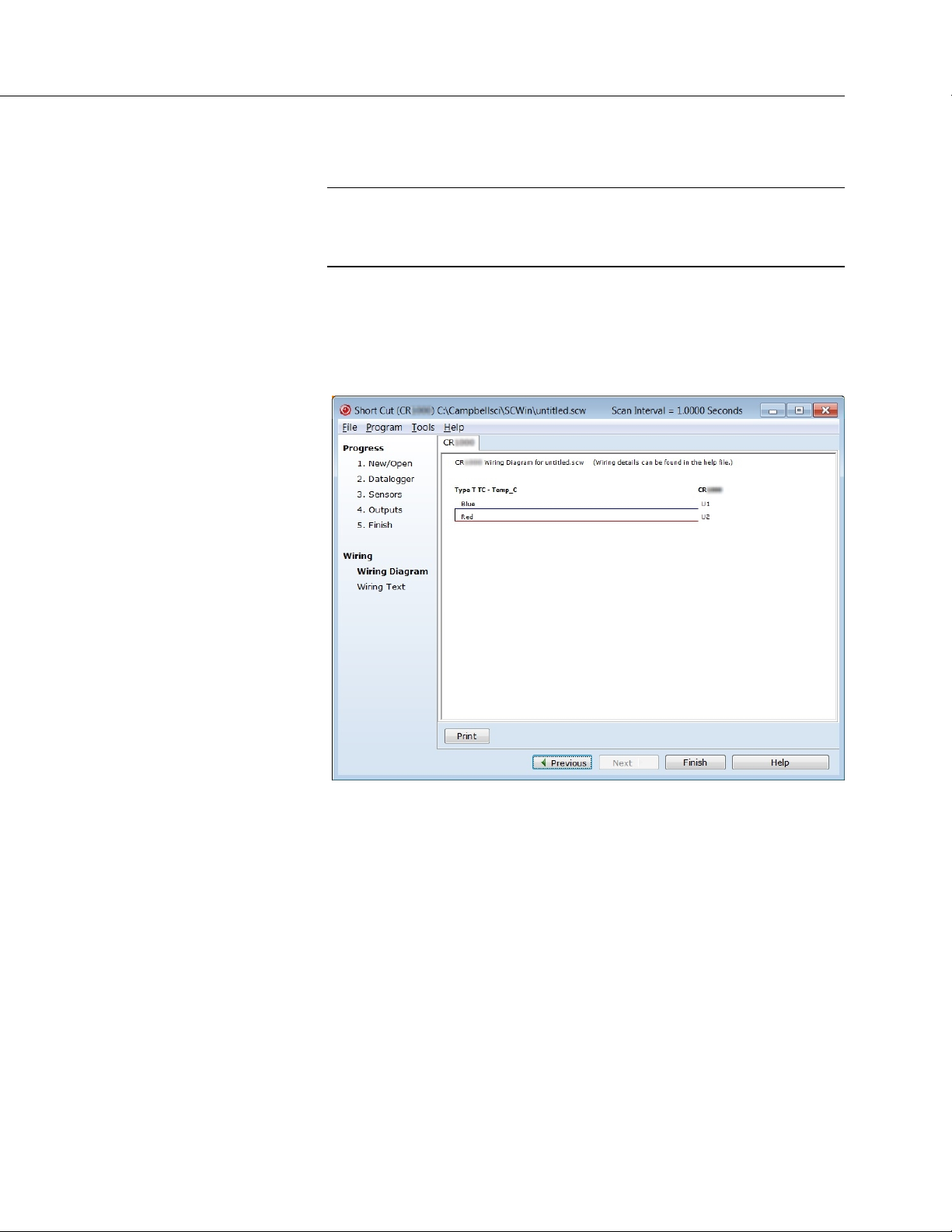
Section 4. Quickstart
49
immediately clicking OK, you accept default options that include selection of
1 sensor and PTemp_C as the reference temperature measurement.
Note BattV (battery voltage) and PTempC (wiring panel temperature)
are default measurements. During normal operations, battery and
temperature can be recorded at least daily to assist in monitoring system
status.
7. In the left pane of the main Short Cut window, click Wiring Diagram. Attach
the physical type-T thermocouple to the CR6 as shown in the diagram. Click
on 3. Sensors in the left pane to return to the sensor selection screen.
FIGURE 4: Short Cut Wiring Diagram Tab
4.6.4.3 Procedure: (Short Cut Step 8)
8. As shown in the following figure, click Next to advance to the Outputs tab,
which displays the list Selected Sensors to the left and data storage tables to
the right under Selected Outputs.
Page 50

Section 4. Quickstart
50
FIGURE 5: Short Cut Outputs Tab
4.6.4.4 Procedure: (Short Cut Steps 9 to 12)
9. As shown in the right-most pane of the previous figure, two output tables (1
Table1 and 2 Table2 tabs) are initially configured. Both tables have a Store
Every field and a drop-down list from which to select the time units. These
are used to set the time intervals when data are stored.
10. Only one table is needed for this tutorial, so remove Table 2. Click 2 Table2
tab, then click Delete Table.
11. Change the name of the remaining table from Table1 to OneMin, and then
change the Store Every interval to 1 Minutes.
12. Add measurements to the table by selecting BattV under Selected Sensors in
the center pane. Click Average in the center column of buttons. Repeat this
procedure for PTemp_C and Temp_C.
4.6.4.5 Procedure: (Short Cut Steps 13 to 14)
13. Click Finish at the bottom of the Short Cut window to compile the program.
At the prompt, name the program MyTemperature. A summary screen, like
the one in the following figure, will appear showing the pre-compiler results.
Pre-compile errors, if any, are displayed here.
Page 51
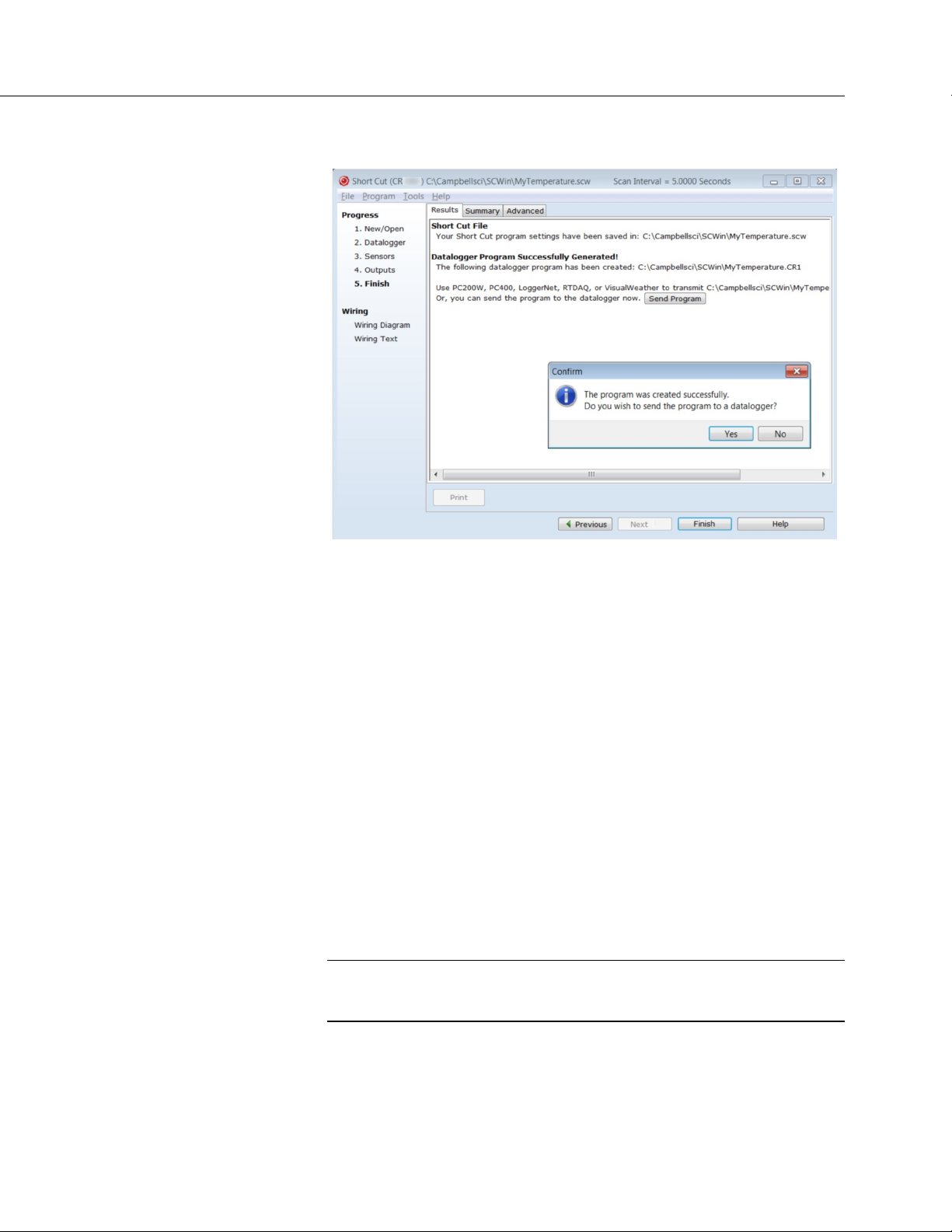
Section 4. Quickstart
51
FIGURE 6: Short Cut Compile Confirmation Window and Results Tab
14. Close this window by clicking on X in the upper right corner.
4.6.5 Send Program and Collect Data
PC200W Datalogger Support Software objectives:
• Send the CRBasic program created by Short Cut in the previous
procedure to the CR6.
• Collect data from the CR6.
• Store the data on the PC.
4.6.5.1 Procedure: (PC200W Step 1)
1. From the PC200W Clock/Program tab, click on Connect (upper left) to
connect the CR6 to the PC. As shown in the following figure, when
connected, the Connect button changes to Disconnect.
CAUTION This procedure assumes there are no data already on the
CR6. If there are data that you want to keep on the CR6, you should
collect it before proceeding to the next step.
Page 52
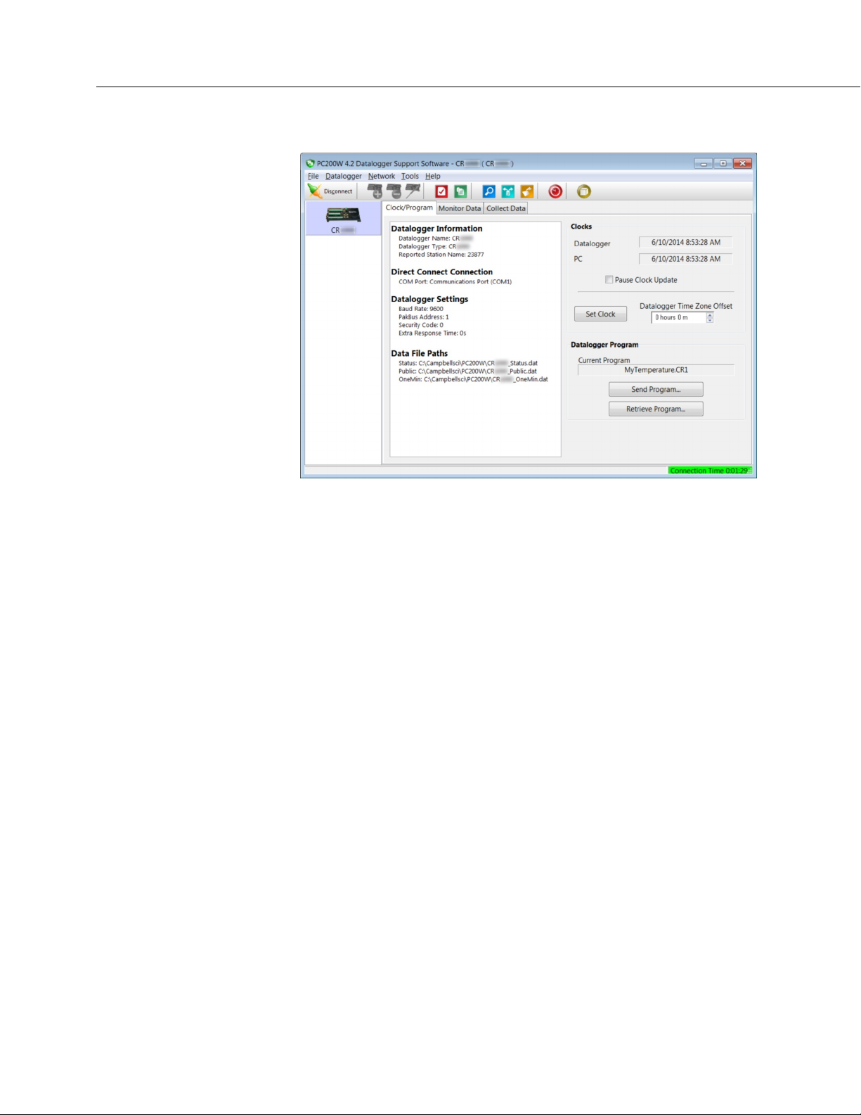
Section 4. Quickstart
52
FIGURE 7: PC200W Main Window
4.6.5.2 Procedure: (PC200W Steps 2 to 4)
2. Click Set Clock (right pane, center) to synchronize the CR6 clock with the
computer clock.
3. Click Send Program... (right pane, bottom). A warning appears that data on
the datalogger will be erased. Click Yes. A dialog box will open. Browse
to the C:\CampbellSci\SCWin folder. Select the MyTemperature.CR6 file.
Click Open. A status bar will appear while the program is sent to the CR6
followed by a confirmation that the transfer was successful. Click OK to
close the confirmation.
4. After sending a program to the CR6, a good practice is to monitor the
measurements to ensure they are reasonable. Select the Monitor Data tab. As
shown in the following figure, PC200W now displays data found in the CR6
Public table.
Page 53
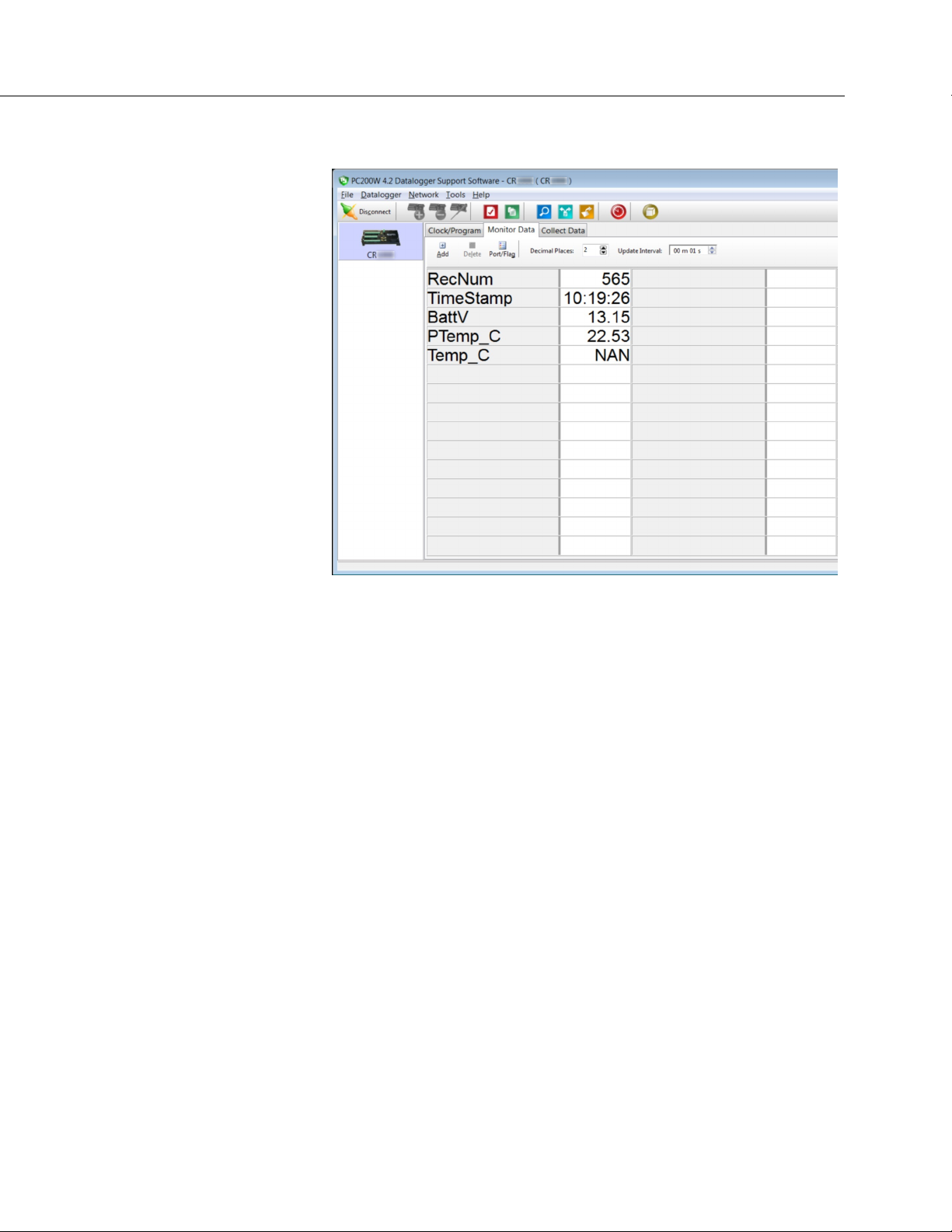
Section 4. Quickstart
53
FIGURE 8: PC200W Monitor Data Tab – Public Table
4.6.5.3 Procedure: (PC200W Step 5)
5. To view the OneMin table, select an empty cell in the display area. Click
Add. In the Add Selection window Tables field, click on OneMin, then click
Paste. The OneMin table is now displayed.
Page 54
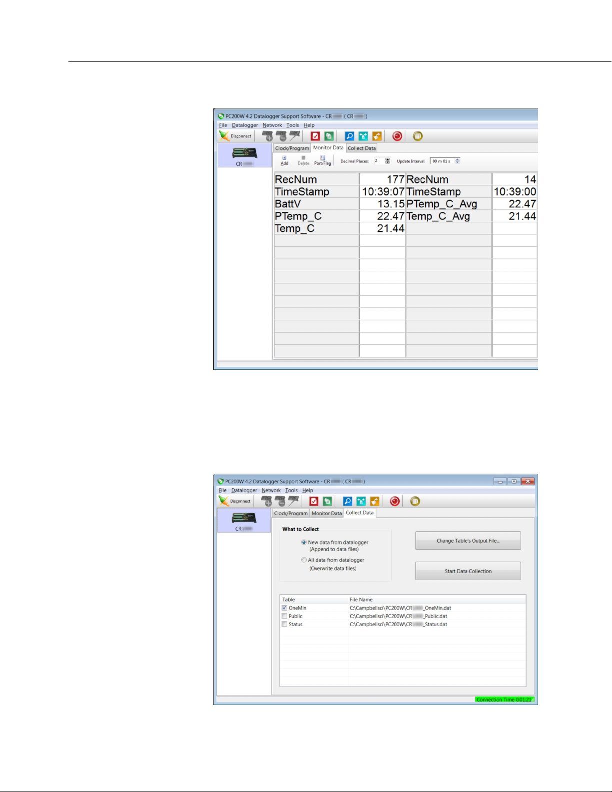
Section 4. Quickstart
54
FIGURE 9: PC200W Monitor Data Tab — Public and OneMin Tables
4.6.5.4 Procedure: (PC200W Step 6)
6. Click on the Collect Data tab and select data to be collected and the storage
location on the PC.
FIGURE 10: PC200W Collect Data Tab
Page 55

55
4.6.5.5 Procedure: (PC200W Steps 7 to 10)
7. Click the OneMin box so a check mark appears in the box. Under What to
Collect, select New data from datalogger.
8. Click on a table in the list to highlight it, then click Change Table's Output
File... to change the name of the destination file.
9. Click on Collect. A progress bar will appear as data are collected, followed
by a Collection Complete message. Click OK to continue.
Section 4. Quickstart
10. To view data, click the
icon at the top of the PC200W window to open
the View utility.
FIGURE 11: PC200W View Data Utility
Page 56
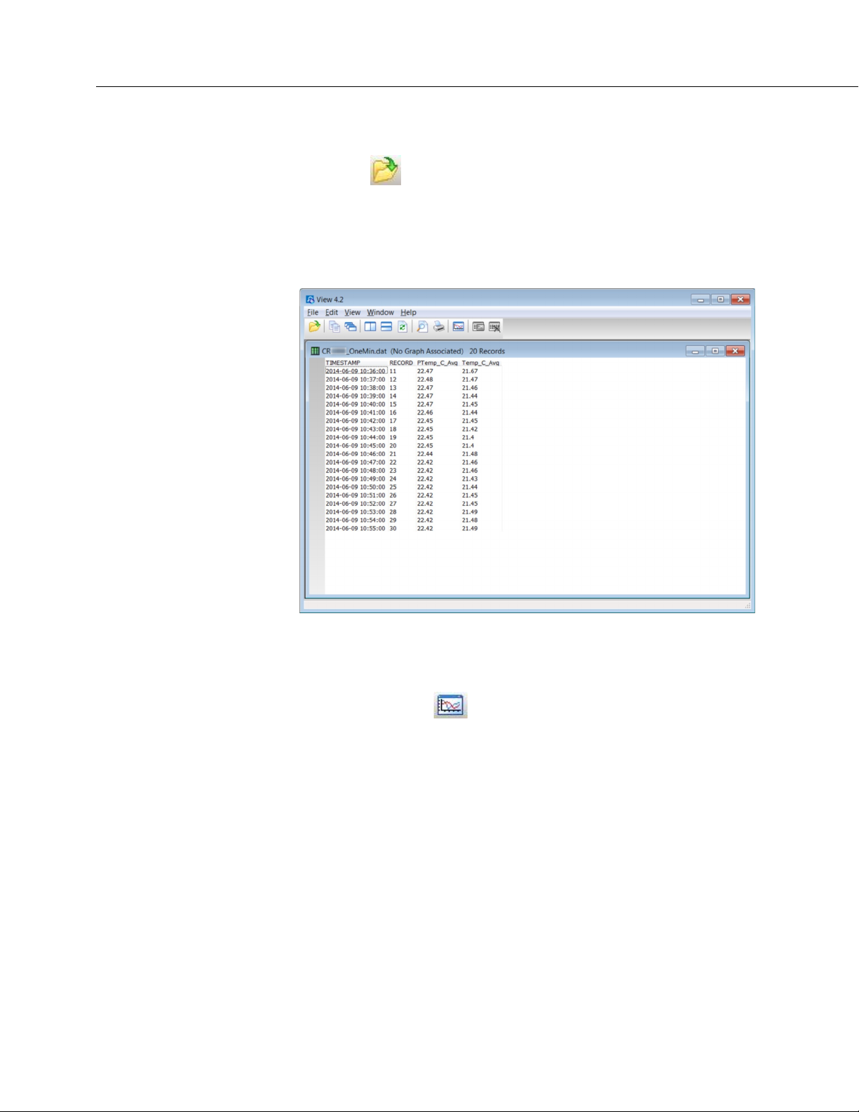
Section 4. Quickstart
56
4.6.5.6 Procedure: (PC200W Steps 11 to 12)
11. Click on to open a file for viewing. In the dialog box, select the
CR6_OneMin.dat file and click Open.
12. The collected data are now shown.
FIGURE 12: PC200W View Data Table
4.6.5.7 Procedure: (PC200W Steps 13 to 14)
13. Click the heading of any data column. To display the data in that column in a
line graph, click the
14. Close the Graph and View windows, and then close the PC200W program.
icon.
Page 57
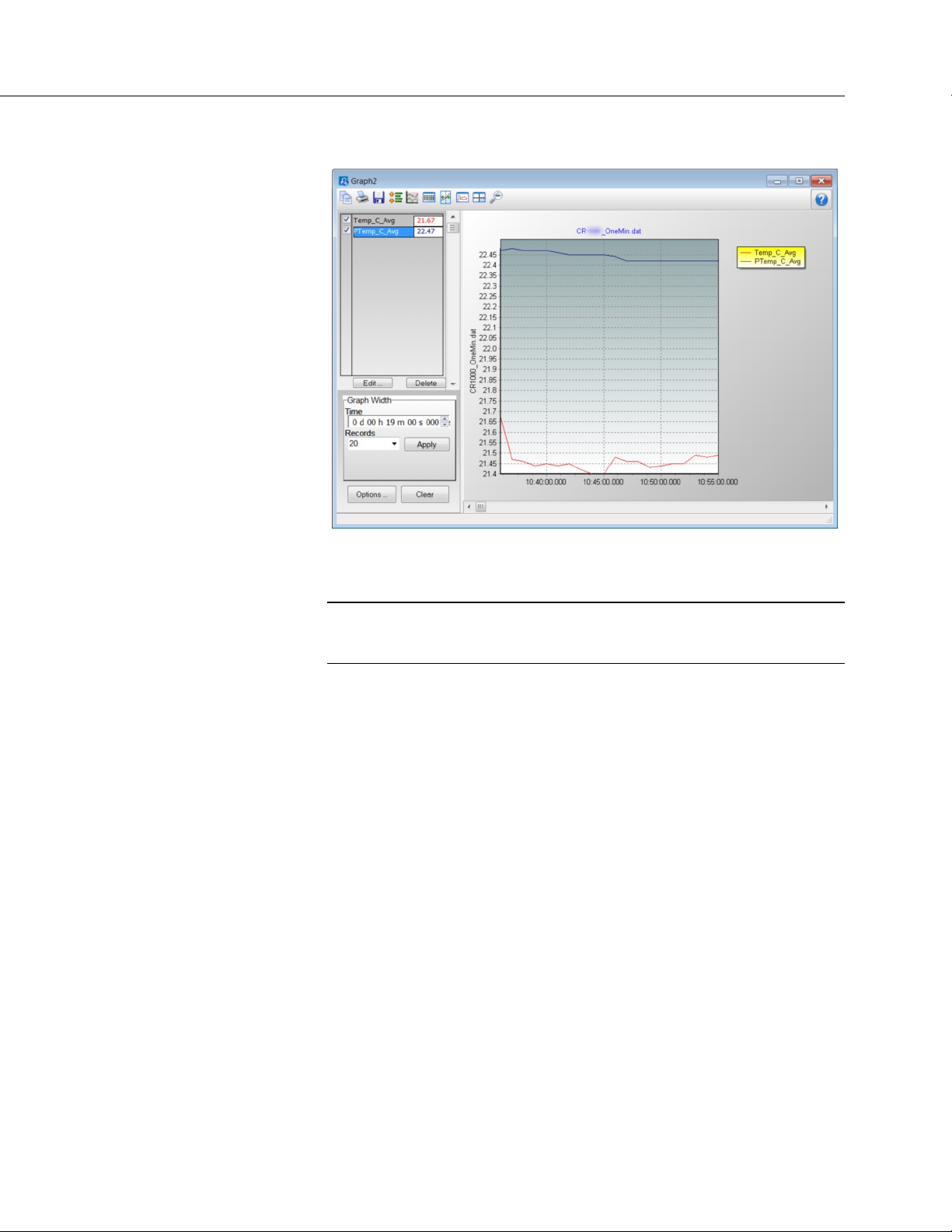
Section 4. Quickstart
57
FIGURE 13: PC200W View Line Graph
4.7 Data Acquisition Systems — Quickstart
Related Topics:
• Data Acquisition Systems — Quickstart (p. 57)
• Data Acquisition Systems — Overview
Acquiring data with a CR6 datalogger requires integration of the following into a
data acquisition system:
• Electronic sensor technology
• CR6 datalogger
• Comms link
• Datalogger support software (p. 97)
A failure in any part of the system can lead to bad data or no data. The concept of
a data acquisition system is illustrated in figure Data Acquisition System
Components
• Sensors
(p. 58) Following is a list of typical system components:
(p. 39) — Electronic sensors convert the state of a phenomenon to
an electrical signal.
(p. 60)
• Datalogger
(p. 40) — The CR6 measures electrical signals or reads serial
characters. It converts the measurement or reading to engineering units,
performs calculations, and reduces data to statistical values. Data are
stored in memory to await transfer to a PC by way of an external storage
device or a comms link.
Page 58

Section 4. Quickstart
58
• Data Retrieval and Comms (p. 43) — Data are copied (not moved) from
the CR6, usually to a PC, by one or more methods using datalogger
support software. Most of these comms options are bi-directional, which
allows programs and settings to be sent to the CR6.
• Datalogger Support Software
(p. 44) — Software retrieves data and sends
programs and settings. The software manages the comms link and has
options for data display.
• Programmable Logic Control
(p. 97) — Some data acquisition systems
require the control of external devices to facilitate a measurement or to
control a device based on measurements. The CR6 is adept at
programmable logic control.
• Measurement and Control Peripherals
(p. 92) — Sometimes, system
requirements exceed the capacity of the CR6. The excess can usually be
handled by addition of input and output expansion modules.
FIGURE 14: Data Acquisition System Components
Page 59

59
5. Overview
You have just received a big box (or several big boxes) from Campbell Scientific,
opened it, spread its contents across the floor, and now you sit wondering what to
do.
Well, that depends.
Probably, the first thing you should understand is the basic architecture of a data
acquisition system. Once that framework is in mind, you can begin to
conceptualize what to do next. So, job one, is to go back to the Quickstart
(p. 39)
section of this manual and work through the tutorial. When you have done that,
and then read the following, you should have the needed framework.
A Campbell Scientific data acquisition system is made up of the following five
basic components:
• Sensors
• Datalogger, which includes:
o Clock
o Measurement and control circuitry
o Memory
o Hardware and firmware to communicate with comms devices
o User-entered CRBasic program
• Power supply
• Comms link or external storage device
• Datalogger support software (p. 579)
The figure Data Acquisition Systems — Overview (p. 60) illustrates a common
CR6-based data acquisition system.
Page 60

Section 5. Overview
60
FIGURE 15: Data Acquisition System — Overview
5.1 Datalogger — Overview
The CR6 datalogger is the main part of the system. It is a precision instrument
designed to withstand demanding environments and to use the smallest amount of
power possible. It has a central-processing unit (CPU), analog and digital
measurement inputs, analog and digital outputs, and memory. An operating
system (firmware) coordinates the functions of these parts in conjunction with the
on-board clock and the CRBasic application program.
Page 61

Section 5. Overview
61
The application program is written in CRBasic, which is a programming language
that includes measurement, data processing, and analysis routines and the
standard BASIC instruction set. For simpler applications, Short Cut
(p. 601), a
user-friendly program generator, can be used to write the progam. For more
demanding programs, use CRBasic Editor
(p. 578).
After measurements are made, data are stored in non-volatile memory. Most
applications do not require that every measurement be recorded. Instead, the
program usually combines several measurements into computational or statistical
summaries, such as averages and standard deviations.
Programs are run by the CR6 in either sequential mode
pipeline mode
(p. 595). In sequential mode, each instruction is executed sequentially
(p. 600) or the more efficient
in the order it appears in the program. In pipeline mode, the CR6 determines the
order of instruction execution.
5.1.1 Wiring Panel — Overview
In the following figure, the CR6 wiring panel is illustrated. The wiring panel is
the interface to most CR6 functions so studying it is a good way to get acquainted
with the CR6. Functions of the terminals are broken down into the following
categories. Each category is hyperlinked to the specification for that function.
The wiring terminals are removable. For applications wherein shock or vibration
is expected, or where strain may exist on the wiring harness, be sure to lock down
the terminals with the screws provided at each end of the blocks.
• Analog input (p. 101)
•
Analog output (p. 108)
•
Pulse counting (p. 110)
•
Digital I/O input (p. 112)
•
Digital I/O output (p. 113)
•
Digital I/O communications (p. 114)
•
Dedicated power output terminal (p. 116)
•
Power input terminal (p. 122)
•
Ground terminals (p. 128)
•
Status lights (p. 129)
Page 62

Section 5. Overview
62
C1 C2 C3 C4 U1 U2 U3 U4 U5 U6 U7 U8 U9 U10 U11 U12 12V SW12
SW12
CS I/O RS
232/CPI
Maximum
FIGURE 16: Wiring Panel
CR6 Wiring Panel Terminal Definitions
Terminal Label
============
Function
Analog Input Function:
Single-ended
Differential
Period average
Vibrating wire2
Vibrating wire with
thermistor
Thermistor
H L H L H L H L H L H L
-1
-2
1
-
12
6
12
6
3
6
Page 63

63
TABLE 2: CR6 Wiring Panel Terminal Definitions
C1 C2 C3 C4 U1 U2 U3 U4 U5 U6 U7 U8 U9 U10 U11 U12 12V SW12
SW12
CS
RS
232/CPI
Maximum
Terminal Label
============
Function
Analog Output Function:
Section 5. Overview
-1
-2
I/O
1
-
Switched-voltage
excitation
Switched-Current
Excitation
12
12
Pulse Counting Function:
Switch closure 16
Low-level Vac
High frequency
6
16
Digital I/O Function:
True RS-232 (TX/RX)
TTL or LVTTL RS-232
(TX/RX)
Half-Duplex RS-485
(A– B+)
Full-Duplex RS-485
(Tx– Tx+ Rx– Rx+)
34
3
8
2
1
SDI-12
SDM
(Data/Clock/Enable)
SPI
(MOSI/SCLK/MISO)
I2C (SDA/SCL)
Control
Status
General I/O 16
Pulse-width modulation
Timer Input
8
1
4
8
16
16
16
16
Page 64

Section 5. Overview
64
C1 C2 C3 C4 U1 U2 U3 U4 U5 U6 U7 U8 U9 U10 U11 U12 12V SW12
SW12
CS I/O RS
232/CPI
Maximum
TABLE 2: CR6 Wiring Panel Terminal Definitions
Terminal Label
============
Function
1
-1
-2
-
Interrupt
Voltage Output5:
12 Vdc
Switched 12 Vdc
3.3 Vdc
5 Vdc
Switched 12 Vdc
Ground Terminals
(input terminal)6
G (power & control)7
RG (100 Ω RS-485)8
(system lug)9
1
If more terminals are needed, terminal expansion modules are available. See section Measurement and Control Peripherals —
Overview
2
Static, VSPECT (p. 608) vibrating wire measurement
3
Requires an interfacing device for sensor input. See the section Hardwire, Single-Connection Comms Devices List (p. 660).
4
Requires an interfacing cable for DB9 I/O. See the section Hardwire, Single-Connection Comms Devices List (p. 660).
5
Check the table Current Source and Sink Limits (p. 124).
6
Best practice is to use the terminal that is bracketed with the input terminals used. When used as a current return, use the
(p. 92).
terminal bracketed with the U terminal that is configured for current excitation.
7
Use for power and control returns.
8
Use only for RS-485 communications.
9
Connect to Earth or chassis ground with large gage wire.
16
1
2
16
16
2
6
4
1
1
Note U and C terminals are paired. Pairs are U1/U2, C1/C2 and so forth. If one of a pair is configured for digital I/O, pulse
counting, or analog input or output (U channels only), the other of the pair can only be used in that same function class. Likewise, if
one of a pair is configured for 3.3 V or 5 V logic level, the other of the pair can only be used with that same logic level. SDI-12
and low-level AC terminals, while using only one terminal in a pair, tie up both terminals in the pair. Short Cut program
configuration software knows these rules and fills in unused terminals when it can.
Note When a U or C terminal is configured for switch closure or high-frequency pulse, it will be internally configured as a pull-up
to logic high (p. 590).
Page 65

65
Other Wiring Panel Features
Section 5. Overview
RG
CHG +, CHG –
BAT +, BAT –
Ethernet
USB
(lug)
Telemetry status lights
(LEDs)
Power status lights
(LEDs)
MicroSD / Act status
light (LED)
Resistive Ground. 100 ohm, 2 watt resistor to ground. Used to
decouple ground on RS-485 signal.
16 to 32 Vdc only. Able to handle a 24 V solar panel with
over-charge voltage of 45 Vdc.
VRLA (valve-regulated lead-acid) battery only, 7 to 24 Ahr typical,
or a regulated power source if not using the Charge +/- terminals.
Not using Charge terminals bypasses charge circuit inefficiencies.
10 to 16 Vdc allowable voltage levels.
RJ45, 10/100 Mbps, Protocols supported: IP V4,IP V6, PakBus,
Modbus, DNP3, HTTP/HTTPS, PPP, TLSv1.1, TCP, UDP, DHCP,
FTP/FTPS, POP3/STLS, SMTP/STLS, XML, JSON
USB micro B 2.0 full speed for computer connection; 12 Mbps
Heavy gauge connection to earth ground
See Status Lights — Specifications
(p. 129).
See Status Lights — Specifications (p. 129).
See Status Lights — Specifications
(p. 129).
Ethernet status lights
(LEDs)
See Status Lights — Specifications (p. 129).
Antenna connection WiFi, Cellular, SS 900Mhz or 2.4Ghz
Supports CPI networks.
Can be used for true RS-232 Tx/Rx and handshaking. RS-232 (DB9
pin 5) ground to both the resistive ground pins and the shield of the
CPI / RS-232
cable. Pin 7 of the RJ45 will function as the DTR (output CR6) and
pin 8 of the RJ45 will function as the CTS (input CR6). Pin 1 of the
RJ45 will function as the TX (output CR6) and pin 2 of the RJ45 will
function as the RX (input CR6)
.
5.1.1.1 Switched Voltage Output — Overview
Related Topics:
• Switched Voltage Output — Specifications (p. 114)
• Switched Voltage Output — Overview (p. 65)
• Switched Voltage Output — Details (p. 473)
• Omnibus Current Source and Sink Limits — Specifications (p. 124)
• PLC Control — Overview (p. 97)
• PLC Control Modules — Overview (p. 477)
• PLC Control Modules — Lists (p. 655)
U and C terminals are selectable as binary inputs, control outputs, or
communication ports. See Measurements — Overview
(p. 71) for a summary of
Page 66
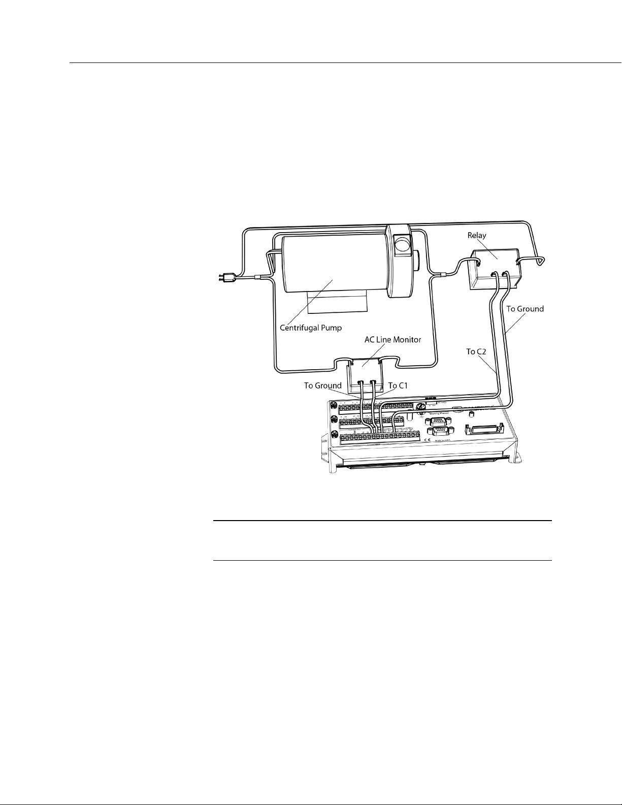
Section 5. Overview
66
measurement functions. Other functions include device-driven interrupts,
asynchronous communications and SDI-12 communications. Table CR6
Terminal Definitions
(p. 62) summarizes available options.
Figure Control and Monitoring with U or C Terminals
(p. 66) illustrates a simple
application wherein a C terminal configured for digital input and another
configured for control output are used to control a device (turn it on or off) and
monitor the state of the device (whether the device is on or off).
FIGURE 17: Control and Monitoring with U or C Terminals
5.1.1.2 Voltage and Current Excitation — Overview
Related Topics:
• Voltage (p. 108) and Current (p. 66)Excitation — Specifications (p. 108)
• Voltage and Current Excitation — Overview (p. 66)
The CR6 has several terminals, and terminal configurations, designed to supply
switched voltage to peripherals, sensors, or control devices:
• Voltage Excitation (switched-analog output) — U terminals configured
for voltage excitation output supply precise voltage. These terminals are
regularly used with resistive-bridge measurements..
• Digital I/O — U and C terminals configured for on / off and PWM (pulse
width modulation) or PDM (pulse duration modulation) .
• Switched 12 Vdc — SW12 terminals. Primary battery voltage under
program control to control external devices (such as humidity sensors)
requiring nominal 12 Vdc.
Page 67

Section 5. Overview
67
• Continuous Analog Output (CAO) — available by adding a peripheral
analog output device available from Campbell Scientific. Refer to
Analog-Output Modules — List
(p. 477) for information on available
expansion modules.
• Switched Current Excitation — any U terminal configured for current
excitation with return to
terminal. These terminals are regularly
used with resistive-bridge measurements.
5.1.1.3 Power Terminals
5.1.1.3.1 Power In Terminals
The – BAT +– CHG + connector is the connection point for external power
supply components.
5.1.1.3.2 Power Out Terminals
Note Refer to Switched-Voltage Output — Details (p. 473) for more
information about using the CR6 as a power supply for sensors and
peripheral devices.
The CR6 can be used as a power source for sensors and peripherals. The
following voltages are available:
• 12V terminals: unregulated nominal 12 Vdc. This supply closely tracks
the primary CR6 supply voltage, so it may rise above or drop below the
power requirement of the sensor or peripheral. Precautions should be
taken to prevent damage to sensors or peripherals from over- or
under-voltage conditions, and to minimize the error associated with the
measurement of underpowered sensors. See Power Supplies —
Overview
(p. 93).
• U and C terminals configured for power out — regulated ±2500 mV
• U terminals configured for power out — 3.3 or 5 Vdc
• C terminals configured for power out — 3.3 or 5 Vdc
5.1.1.4 Communication Ports — Overview
Related Topics:
• Communication Ports — Overview (p. 67)
• Data Retrieval and Comms — Overview (p. 85)
• CPI Port and CDM Devices — Overview (p. 70)
• PakBus — Overview (p. 87)
• RS-232 and TTL (p. 466)
Page 68

Section 5. Overview
68
The CR6 is equipped with hardware ports that allow communication with other
devices and networks, such as:
• PC
• Smart sensors
• Modbus and DNP3 networks
• Ethernet
• Modems
• Campbell Scientific PakBus networks
• Other Campbell Scientific dataloggers
• Campbell Scientific datalogger peripherals
Communication ports include:
• CS I/O
• RS-232
• USB
• SDI-12
• SDM
• CPI
• Ethernet
• MicroSD card slot (requires a micro SD card)
5.1.1.4.1 CS I/O Port
Read More See Serial Port Pinouts (p. 643).
• One nine-pin port, labeled CS I/O, for communicating with a PC or
modem through Campbell Scientific communication interfaces, modems,
or peripherals. CS I/O comms interfaces are listed in the appendix
Serial I/O Modules — List
(p. 653).
Note Keep CS I/O cables short (maximum of a few feet).
Page 69

69
5.1.1.4.2 RS-232 Ports
Note RS-232 communications normally operate well up to a transmission
cable capacitance of 2500 picofarads, or approximately 50 feet of
commonly available serial cable.
Section 5. Overview
• One RJ45 port, labeled CPI/RS-232, normally used to communicate
with another manufacturer's modem or smart sensor. Purchase Campbell
Scientific pn 31055 (male DTE) or pn 31056 (female DCE, null modem)
as an adapter. Conventional RJ45 to RS-232 adapters available from
third-party vendors are NOT compatible.
Read More See Serial Port Pinouts
(p. 643).
• Two-terminal (TX and RX) RS-232 ports can be configured:
o Two true RS-232 ports configured from C terminals.
o Six TTL ports configured from U terminals.
Note RS-232 ports are not isolated
(p. 588).
5.1.1.4.3 USB Port
One micro-B USB port, labeled USB, for communicating with a PC with
datalogger support software
The USB connection only powers the programming, configuration, and analog
measurement circuitry of the CR6. A USB COM port for the CR6 is created
automatically on your PC when first you install the driver (this is done
automatically when you install LoggerNet) and second, you connect the CR6 to
the PC over the supplied USB cable. Once established, the CR6 USB port may
disappear from the PC COM port lists momentarily while the CR6 is occupied by
a system reset. If servicing multiple dataloggers over USB with the same PC,
you may want to use the USBEnumerate
(p. 579). Use the USB cable supplied with the CR6.
(p. 640) setting.
Some computer and CR6 combinations will not communicate unless the USB
cable between them does not have ferrite bead chokes.
5.1.1.4.4 Micro SD Card Slot
A micro-SD card slot for a removable, supplemental, memory card. See Status
Lights (LEDs)
(p. 129).
5.1.1.4.5 SDI-12 Ports
Read More See the section Serial I/O: SDI-12 Sensor Support — Details
(p. 308).
Page 70

Section 5. Overview
70
5.1.1.4.6 SDM Port
5.1.1.4.7 CPI Port and CDM Devices — Overview
SDI-12 is a 1200 baud protocol that supports many smart sensors. Each port
requires one terminal and supports up to 16 individually addressed sensors.
• Up to eight ports configured from C or U terminals.
SDM is a protocol proprietary to Campbell Scientific that supports several
Campbell Scientific digital sensor and comms input and output expansion
peripherals and select smart sensors.
• Up to four SDM ports configured from U or C terminals.
Related Topics:
• CPI Port and CDM Devices — Overview (p. 70)
• CPI Port and CDM Devices — Details (p. 545)
CPI is a new proprietary protocol that supports an expanding line of Campbell
Scientific CDM modules. CDM modules are higher-speed input- and
output-expansion peripherals. CPI ports also enable networking between
compatible Campbell Scientific dataloggers. Consult the manuals for CDM
modules for more information.
• One RJ45 port labeled CPI.
5.1.1.4.8 Ethernet Port
Read More See the section TCP/IP — Details (p. 517).
• One RJ45 port labeled Ethernet.
5.1.1.5 Grounding — Overview
Related Topics:
• Grounding — Overview (p. 70)
• Grounding — Details (p. 141)
Proper grounding lends stability and protection to a data acquisition system. It is
the easiest and least expensive insurance against data loss — and often the most
neglected. The following terminals are provided for connection of sensor and CR6
datalogger grounds:
Signal ground reference for single-ended analog inputs, pulse
•
inputs, excitation returns, and as a ground for sensor shield wires. Signal
returns for pulse inputs should use
input terminal. Current loop sensors, however, should be grounded to
power ground.
terminals located next to the pulse
Page 71

Section 5. Overview
71
• G Power ground return for SW12, 12V terminals, current loop sensors,
and U or C configured for control. Use of G grounds for these outputs
minimizes potentially large current flow through the
analog-voltage-measurement section of the wiring panel, which can
cause single-ended voltage measurement errors.
• RG Resistive ground return for RS-485 connections.
Earth ground lug connection point for a heavy-gage earth-ground
•
wire. A good earth connection is necessary to secure the ground potential
of the CR6 and shunt transients away from electronics. Minimum 14
AWG wire is recommended.
5.2 Measurements — Overview
Related Topics:
• Sensors — Quickstart (p. 39)
• Measurements — Overview
• Measurements — Details
• Sensors — Lists
(p. 657)
(p. 71)
(p. 387)
Most electronic sensors, whether or not they are supplied by Campbell Scientific,
can be connected directly to the CR6.
Manuals that discuss alternative input routes, such as external multiplexers,
peripheral measurement devices, or a wireless sensor network, can be found at
www.campbellsci.com/manuals.
This section discusses direct sensor-to-datalogger connections and applicable
CRBasic programming to instruct the CR6 how to make, process, and store the
measurements. Terminals on the CR6 wiring panel, as described in table CR6
Terminal Definitions
(p. 62), are configurable for the measurements discussed in the
following sections:
5.2.1 Time Keeping — Overview
Related Topics:
• Time Keeping — Overview (p. 71)
• Time Keeping — Details (p. 387)
Measurement of time is an essential function of the CR6. Time measurement with
the on-board clock enables the CR6 to attach time stamps to data, measure the
interval between events, and time the initiation of control functions.
5.2.2 Analog Measurements — Overview
Related Topics:
• Analog Measurements — Overview (p. 71)
• Analog Measurements — Details
(p. 389)
Page 72

Section 5. Overview
72
5.2.2.1 Voltage Measurements — Overview
Analog sensors output a continuous voltage or current signal that varies with the
phenomena measured. Sensors compatible with the CR6 output a voltage. The
CR6 can also measure analog current output when the current is converted to
voltage by using a resistive shunt.
Sensor connection is to U terminals configured for differential or single-ended
inputs. For example, differential channel U1 is comprised of terminals U1 and U2,
with U1 as high and U2 as low.
Related Topics:
• Voltage Measurements — Specifications (p. 102)
• Voltage Measurements — Overview
• Voltage Measurements — Details
(p. 72)
(p. 415)
• Maximum input voltage range: ±5000 mV
• Measurement resolution range: 0.05 µV to 30 µV RMS
Single-ended and differential connections are illustrated in the figures Analog
Sensor Wired to Single-Ended Channel #1
Differential Channel #1
(p. 73). Table CR6 Terminal Definitions (p. 62) lists the
(p. 73) and Analog Sensor Wired to
available analog input configurations.
Conceptually, analog voltage sensors output two signals: high and low. For
example, a sensor that outputs 1000 mV on the high lead and 0 mV on the low has
an overall output of 1000 mV. A sensor that outputs 2000 mV on the high lead
and 1000 mV on the low also has an overall output of 1000 mV. Sometimes, the
low signal is simply sensor ground (0 mV). A single-ended measurement
measures the high signal with reference to ground, with the low signal tied to
ground. A differential measurement measures the high signal with reference to
the low signal. Each configuration has a purpose, but the differential
configuration is usually preferred.
A differential configuration may significantly improve the voltage measurement.
Following are conditions that often indicate that a differential measurement
should be used:
• Ground currents cause voltage drop between the sensor and the
signal-ground terminal. Currents >5 mA are usually considered
undesirable. These currents may result from resistive-bridge sensors
using voltage excitation, but these currents only flow when the voltage
excitation is applied. Return currents associated with voltage excitation
cannot influence other single-ended measurements of small voltage
unless the same voltage-excitation terminal is enabled during the
unrelated measurements.
• Measured voltage is less than 200 mV.
Page 73
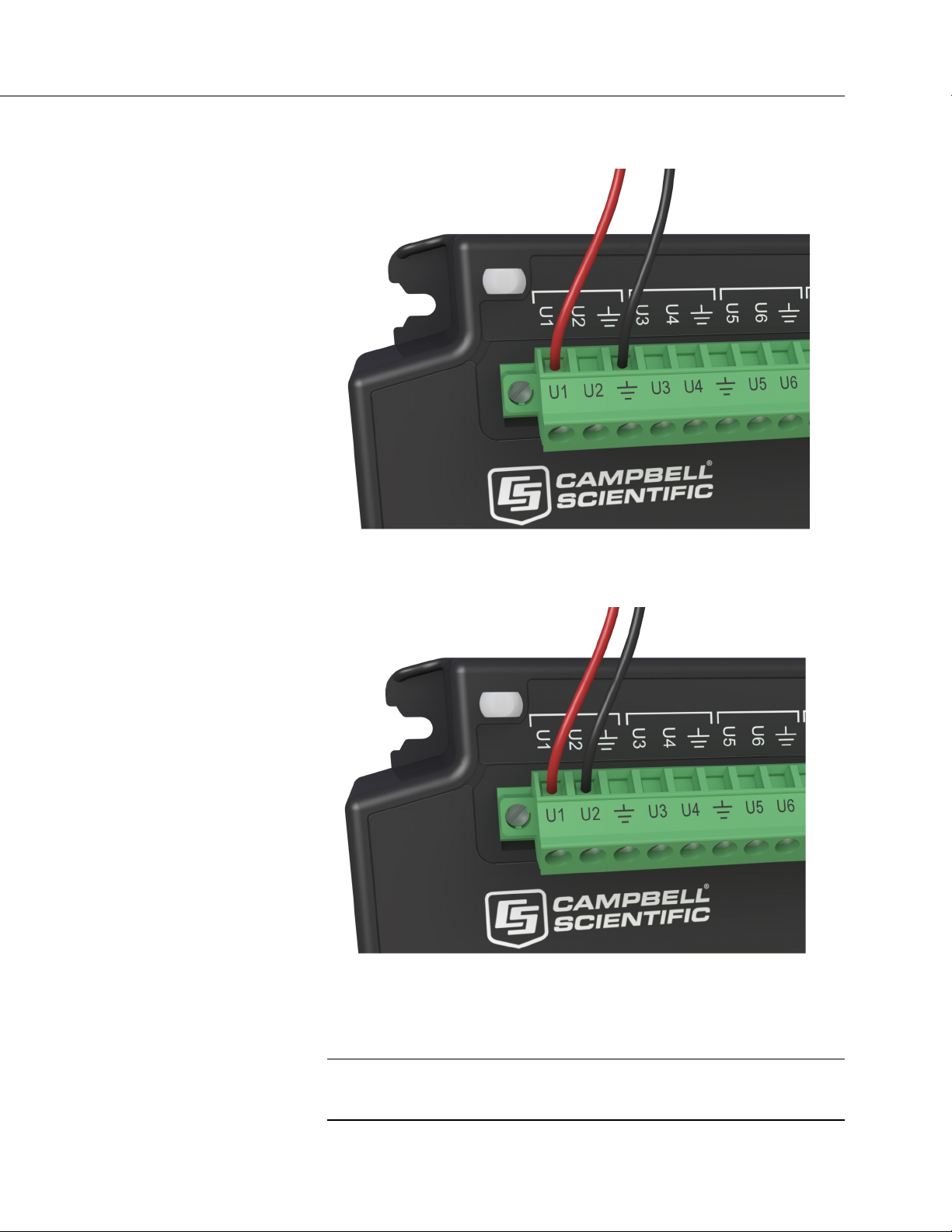
Section 5. Overview
73
FIGURE 18: Analog Sensor Wired to Single-Ended Channel #1
FIGURE 19: Analog Sensor Wired to Differential Channel #1
5.2.2.1.1 Single-Ended Measurements — Overview
Related Topics:
• Single-Ended Measurements — Overview (p. 73)
• Single-Ended Measurements — Details
(p. 422)
Page 74

Section 5. Overview
74
A single-ended measurement measures the difference in voltage between the
terminal configured for single-ended input and the reference ground. While
differential measurements are usually preferred, a single-ended measurement is
often adequate in applications wherein some types of noise are not present and
care is taken to avoid problems caused by ground currents
(p. 585). Examples of
applications wherein a single-ended measurement may be preferred include:
• Not enough differential terminals available. Differential measurements
use twice as many U terminals as do single-ended measurements.
• Sensor is not designed for differential measurements. Many Campbell
Scientific sensors are not designed for differential measurement, but the
draw backs of a single-ended measurement are usually mitigated by large
programmed excitation and/or sensor output voltages.
However, be aware that because a single-ended measurement is referenced to CR6
ground, any difference in ground potential between the sensor and the CR6 will
result in error, as emphasized in the following examples:
• If the measuring junction of a thermocouple used to measure soil
temperature is not insulated, and the potential of earth ground is greater
at the sensor than at the point where the CR6 is grounded, a measurement
error will result. For example, if the difference in grounds is 1 mV, with
a copper-constantan thermocouple, the error will be approximately 25
°C.
• If signal conditioning circuitry, such as might be found in a gas analyzer,
and the CR6 use a common power supply, differences in current drain
and lead resistance often result in different ground potentials at the two
instruments despite the use of a common ground. A differential
measurement should be made on the analog output from the external
signal conditioner to avoid error.
5.2.2.1.2 Differential Measurements — Overview
Related Topics:
• Differential Measurements — Overview (p. 74)
• Differential Measurements — Details
(p. 422)
Summary Use a differential configuration when making voltage
measurements, unless constrained to do otherwise.
A differential measurement measures the difference in voltage between two input
terminals. Its autosequence is characterized by multiple measurements, the
results of which are autoaveraged before the final value is reported. For example,
the sequence on a differential measurement using the VoltDiff() instruction
involves two measurements — first with the high input referenced to the low, then
with the inputs reversed. Reversing the inputs before the second measurement
cancels noise common to both leads as well as small errors caused by junctions of
different metals that are throughout the measurement electronics.
Page 75

Section 5. Overview
75
5.2.2.2 Current Measurements — Overview
Related Topics:
• Current Measurements — Overview (p. 75)
• Current Measurements — Details
(p. 415)
A measurement of current is accomplished through the use of external resistors to
convert current to voltage, then measure the voltage as explained in the section
Differential Measurements — Overview
(p. 74). The voltage is measured with the
CR6 voltage measurement circuitry. U terminals can be configured to supply
precise current excitation for use with resistive bridges.
5.2.2.3 Resistance Measurements — Overview
Related Topics:
• Resistance Measurements — Specifications (p. 106)
• Resistance Measurements — Overview (p. 75)
• Resistance Measurements — Details (p. 406)
• Measurement: RTD, PRT, PT100, PT1000 (p. 326)
Many analog sensors use some kind of variable resistor as the fundamental
sensing element. As examples, wind vanes use potentiometers, pressure
transducers use strain gages, and temperature sensors use thermistors. These
elements are placed in a Wheatstone bridge or related circuit. With the exception
of PRTs, another type of variable resistor. See Measurement: RTD, PRT, PT100,
PT1000
resistors into a resistor bridge. Sensor manufacturers consider many criteria
when deciding what type of resistive bridge to use for their sensors. The CR6
can measure most bridge circuit configurations.
(p. 326). This manual does not give instruction on how to build variable
5.2.2.3.1 Voltage Excitation
Bridge resistance is determined by measuring the difference between a known
voltage applied to the excitation (input) arm of a resistor bridge and the voltage
measured on the output arm. The CR6 supplies a precise-voltage excitation via
U terminals configured for voltage excitation output. Return voltage is measured
on U terminals configured for single-ended or differential input. Examples of
bridge-sensor wiring using voltage excitation are illustrated in figures Half-Bridge
Wiring — Wind Vane Potentiometer
Transducer
(p. 77).
(p. 76) and Full-Bridge Wiring — Pressure
Page 76

Section 5. Overview
76
FIGURE 20: Half-Bridge Wiring Example — Wind Vane Potentiometer
Page 77

Section 5. Overview
77
FIGURE 21: Full-Bridge Wiring Example — Pressure Transducer
5.2.2.3.2 Current Excitation
Resistance can also be measured by supplying a precise current and measuring the
return voltage. The CR6 supplies a precise current from terminals configured for
current excitation. Return voltage is measured on U terminals configured for
single-ended or differential analog input. Examples of bridge-sensor wiring
using current excitation are illustrated in FIGURE: PT100 Resistance()
Basic-Circuit Schematic
(p. 344).
Page 78

Section 5. Overview
78
5.2.2.4 Strain Measurements — Overview
5.2.3 Pulse Measurements — Overview
Related Topics:
• Strain Measurements — Overview (p. 78)
• Strain Measurements — Details
• FieldCalStrain() Examples
(p. 413)
(p. 296)
Strain gage measurements are usually associated with structural-stress analysis.
Related Topics:
• Pulse Measurements — Specifications (p. 110)
• Pulse Measurements — Overview (p. 78)
• Pulse Measurements — Details (p. 438)
The output signal generated by a pulse sensor is a series of voltage waves. The
sensor couples its output signal to the measured phenomenon by modulating wave
frequency. The CR6 detects the state transition as each wave varies between
voltage extremes (high-to-low or low-to-high). Measurements are processed and
presented as counts, frequency, or timing data.
U and C terminals are configurable for pulse input to measure counts or frequency
from the following signal types:
• High-frequency 5 Vdc square-wave
• Switch closure
• Low-level ac
• State
• Edge counting
• Edge timing
Note A period-averaging sensor has a frequency output, but it is
connected to a U terminal configured for period-average input and
measured with the PeriodAverage() instruction. See Period Averaging
— Overview
(p. 81).
5.2.3.1 Pulses Measured
The CR6 measures three types of pulse outputs, which are illustrated in the figure
Pulse Sensor Output Signal Types
(p. 79).
Page 79

Section 5. Overview
79
FIGURE 22: Pulse Sensor Output Signal Types
5.2.3.2 Pulse Input Channels
The chart CR6 Terminal Definitions (p. 62) shows which terminals can be
configured as pulse input channels and the types of pulse measurements made.
5.2.3.3 Pulse Sensor Wiring
Read More See Pulse Measurement Tips (p. 445).
An example of a pulse sensor connection is illustrated in figure Pulse Input
Wiring Example — Anemometer Switch
wires, one of which is ground. Connect the ground wire to a
terminal. Connect the other wire to a U or C terminal configured for pulse input.
Sometimes the sensor will require power from the CR6, so there may be two
added wires — one of which will be power ground. Connect power ground to a
G terminal. Do not confuse the pulse wire with the positive power wire, or
damage to the sensor or CR6 may result. Some switch closure sensors may
require a pull-up resistor. Pulse input terminals can be configured in the program
to use internal pull-up (default) or pull-down resistors.
(p. 80). Pulse sensors have two active
(signal ground)
Page 80
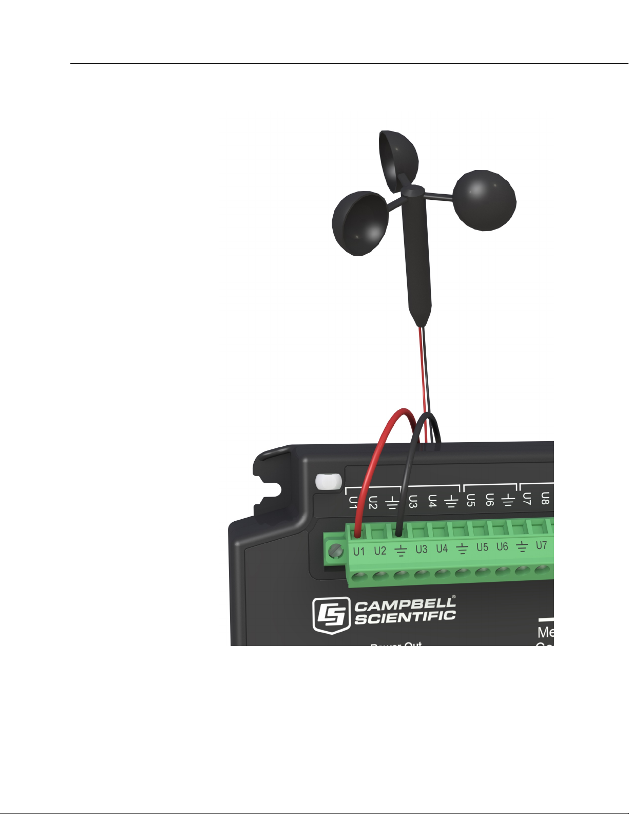
Section 5. Overview
80
FIGURE 23: Pulse Input Wiring Example — Anemometer
Page 81

Section 5. Overview
81
5.2.4 Period Averaging — Overview
Related Topics:
• Period Average Measurements — Specifications (p. 107)
• Period Average Measurements — Overview (p. 81)
• Period Average Measurements — Details (p. 465)
CR6 U terminals can be configured to measure period average. .
Note Both pulse count and period average measurements are used to
measure frequency output sensors. Yet pulse count and period average
measurement methods are different. Pulse count measurements use
dedicated hardware — pulse count accumulators, which are always
monitoring the input signal, even when the CR6 is between program
scans. In contrast, period average measurement instructions only monitor
the input signal during a program scan. Consequently, pulse count scans
can usually be much less frequent than period average scans. Pulse
counters may be more susceptible to low-frequency noise because they
are always "listening", whereas period averaging may filter the noise by
reason of being "asleep" most of the time. Pulse count measurements are
not appropriate for sensors that are powered off between scans, whereas
period average measurements work well since they can be placed in the
scan to execute only when the sensor is powered and transmitting the
signal.
Period average measurements use a high-frequency digital clock to
measure time differences between signal transitions, whereas pulse count
measurements simply accumulate the number of counts. As a result,
period average measurements offer much better frequency resolution per
measurement interval, as compared to pulse count measurements. The
frequency resolution of pulse count measurements can be improved by
extending the measurement interval by increasing the scan interval and by
averaging. For information on frequency resolution, see Frequency
Resolution
(p. 442).
5.2.5 Vibrating Wire Measurements — Overview
Related Topics:
• Vibrating Wire Measurements — Specifications (p. 107)
• Vibrating Wire Measurements — Overview
• Vibrating Wire Measurements — Details
Vibrating wire sensors are the sensor of choice in many environmental and
industrial applications that need sensors that will be stable over very long periods,
such as years or even decades. The CR6 can measure these sensors either directly
or through interface modules.
A thermistor included in most sensors can be measured to compensate for
temperature errors.
(p. 81)
(p. 447)
Page 82
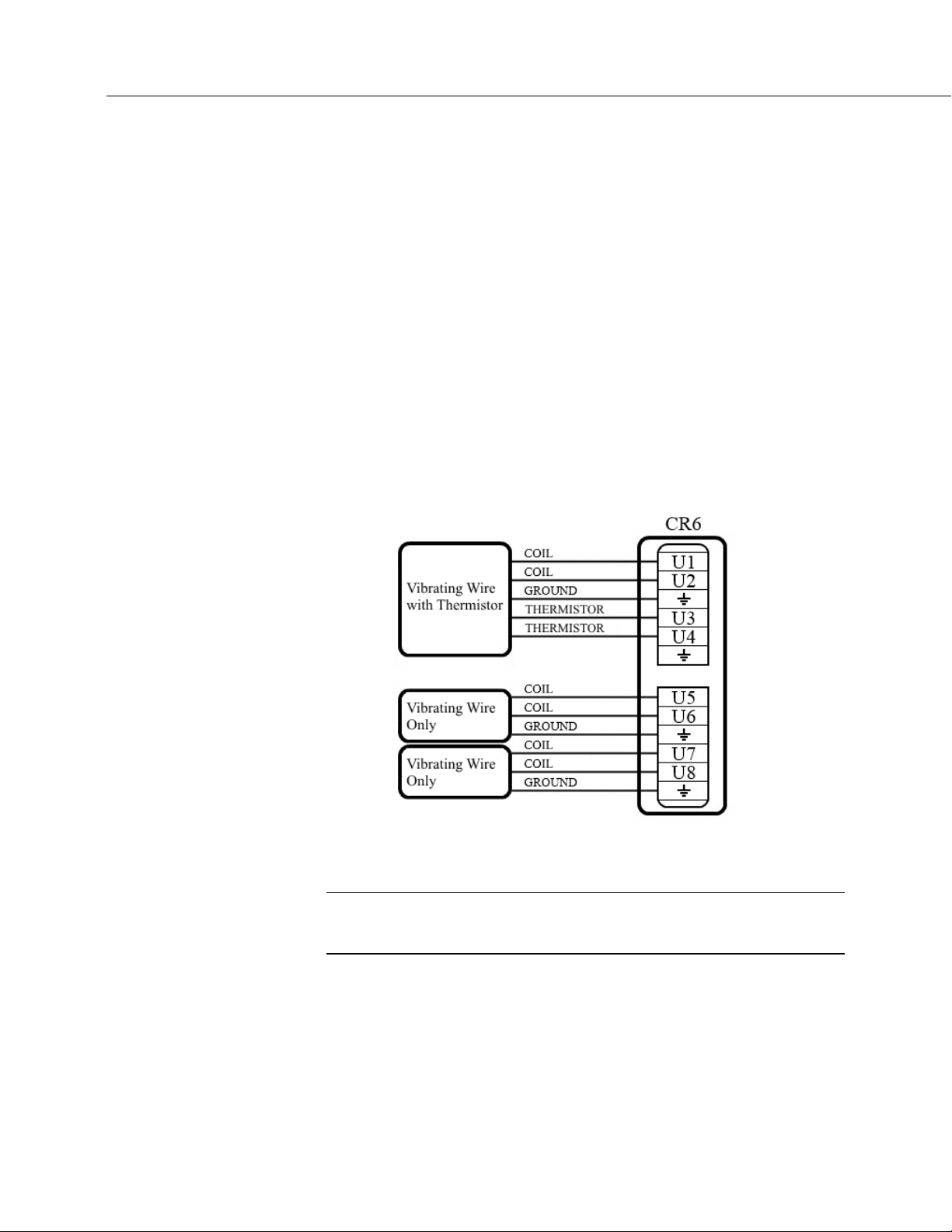
Section 5. Overview
82
U terminals are configurable for VSPECT
(p. 608) vibrating wire analysis.
Dynamic VSPECT measurements require addition of an interface module.
5.2.5.1 VSPECT Quickstart
The figure VSPECT Vibrating Wire Measurement Wiring (p. 82) illustrates an
example of how a vibrating wire sensor with a thermistor, and two vibrating wire
sensors without thermistors, are connected to the CR6. Use Short Cut
create a program and wiring diagram for most types of vibrating wire sensors.
Access the vibrating wire measurement in Short Cut through the Generic
Measurements sensors folder. Short Cut also has measurements for specific
sensor models in the Geotechnical & Structural and Water | Level & Flow
folders. More information about programming the CR6 for vibrating wire
measurements is located in VSPECT Programming
(p. 456).
FIGURE 24: VSPECT Vibrating Wire Measurement Wiring
(p. 601) to
5.2.6 Reading Smart Sensors — Overview
Related Topics:
• Reading Smart Sensors — Overview (p. 82)
• Reading Smart Sensors — Details
A smart sensor is equipped with independent measurement circuitry that makes
the basic measurement and sends measurement and measurement related data to
the CR6. Smart sensors vary widely in output modes. Many have multiple
output options. Output options supported by the CR6 include SDI-12
(p. 356), RS-485 (p. 356), Modbus (p. 525), and DNP3 (p. 525).
RS-232
(p. 466)
(p. 308),
Page 83

Section 5. Overview
83
The following smart sensor types can be measured on the indicated terminals:
• SDI-12 devices: U and C
• Synchronous Devices for Measurement (SDM): U and C
• Smart sensors: U and C terminals, RS-232 port, and CS I/O port with
the appropriate interface.
• Modbus or DNP3 network: RS-232 port and CS I/O port with the
appropriate interface
• Other serial I/O devices: U and C terminals, RS-232 port, and CS I/O
port with the appropriate interface
5.2.6.1 SDI-12 Sensor Support — Overview
Related Topics:
• SDI-12 Sensor Support — Overview (p. 83)
• SDI-12 Sensor Support — Details (p. 469)
• Serial I/O: SDI-12 Sensor Support — Programming Resource (p. 308)
SDI-12 is a smart-sensor protocol that uses one input port on the CR6 and is
powered by 12 Vdc. Refer to the chart CR6 Terminal Definitions
(p. 62), which
indicates U and C terminals that can be configured for SDI-12 input.
5.2.6.2 RS-232 — Overview
Refer to the chart CR6 Terminal Definitions (p. 62), which indicates which terminals
can be configured for RS-232 sensors.
RS-232 sensors can often be connected to U or C terminal pairs configured for
serial I/O or to the CS I/O port with the proper adapter. Ports can be set up for
baud rate, parity, stop-bit, and so forth as described in CRBasic Editor Help.
Page 84
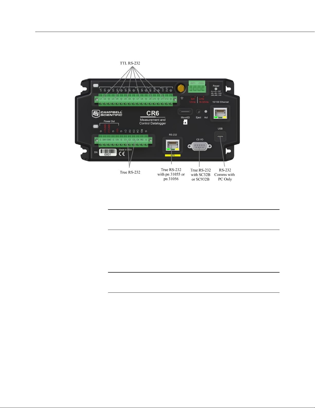
Section 5. Overview
84
FIGURE 25: Terminals Configurable for RS-232 Input
5.2.6.3 RS-485 — Overview
Related Topics:
• RS-485 — Overview
• RS-485 — Details
Refer to the chart CR6 Terminal Definitions (p. 62), which indicates C terminals
that can be configured for RS-485 input.
5.2.7 Field Calibration — Overview
Related Topics:
• Field Calibration — Overview (p. 84)
• Field Calibration — Details
Calibration increases accuracy of a measurement device by adjusting its output, or
the measurement of its output, to match independently verified quantities.
Adjusting sensor output directly is preferred, but not always possible or practical.
By adding FieldCal() or FieldCalStrain() instructions to the CR6 CRBasic
program, measurements of a linear sensor can be adjusted by modifying the
programmed multiplier and offset applied to the measurement without modifying
or recompiling the CRBasic program.
(p. 280)
Page 85

Section 5. Overview
85
5.2.8 Cabling Effects — Overview
Related Topics:
• Cabling Effects — Overview (p. 85)
• Cabling Effects — Details
(p. 470)
Sensor cabling can have significant effects on sensor response and accuracy. This
is usually only a concern with sensors acquired from manufacturers other than
Campbell Scientific. Campbell Scientific sensors are engineered for optimal
performance with factory-installed cables.
5.2.9 Synchronizing Measurements — Overview
Related Topics:
• Synchronizing Measurements — Overview (p. 85)
• Synchronizing Measurements — Details
Timing of a measurement is usually controlled relative to the CR6 clock.
(p. 471)
5.2.9.1 Synchronizing Measurements in the CR6 — Overview
When sensors in a sensor network are measured by a single CR6, measurement
times are synchronized, often within a few milliseconds, depending on sensor
number and measurement type.
5.2.9.2 Synchronizing Measurements in a Datalogger Network — Overview
Large numbers of sensors, cable length restrictions, or long distances between
measurement sites may require use of multiple CR6s.
5.3 Data Retrieval and Comms — Overview
Related Topics:
• Data Retrieval and Comms — Quickstart (p. 43)
• Data Retrieval and Comms — Overview (p. 85)
• Data Retrieval and Comms — Details (p. 514)
• Data Retrieval and Comms Peripherals — Lists (p. 659)
The CR6 communicates with external devices to receive programs, send data, or
join a network. Data are usually moved through a comms link consisting of
hardware and a protocol using Campbell Scientific datalogger support software
663).
Data can also be shuttled with external memory such as a micro-SD card
(CRD: drive) or a Campbell Scientific mass storage media (USB: drive) to the
PC.
(p.
Page 86

Section 5. Overview
86
5.3.1 Data File Formats in CR6 Memory
5.3.2 Data Format on Computer
5.3.3 Mass-Storage Device
Routine CR6 operations store data in binary data tables. However, when the
TableFile() instruction is used, data are also stored in one of several formats in
discrete text files in internal or external memory. See Memory Drives —
On-board
(p. 493) for more information on the use of the TableFile() instruction.
CR6 data stored on a PC with datalogger support software (p. 663) are formatted as
either ASCII or binary depending on the file type selected in the support software.
Consult the software manual for details on available data-file formats.
Caution When removing a Campbell Scientific mass storage device
(thumb drive) from the CR6, do so only when the LED is not lit or flashing.
Removing the device while it is active can cause data corruption.
Data stored on a SC115 Campbell Scientific mass storage device can be retrieved
via a comms link to the CR6 if the device remains on the CS I/O port. Data can
also be retrieved by removing the device, connecting it to a PC, and copying off
files using Windows File Explorer.
5.3.4 Memory Card (CRD: Drive) — Overview
Related Topics:
• Memory Card (CRD: Drive) — Overview (p. 86)
• Memory Card (CRD: Drive) — Details (p. 495)
• Memory Cards and Record Numbers (p. 500)
• Data Output: Writing High-Frequency Data to Memory Cards (p. 268)
• File System Errors (p. 512)
• Data Storage Devices — List (p. 661)
• Data File Format Examples (p. 498)
• Data Storage Drives Table (p. 492)
Caution Observe the following precautions when using memory cards:
• Before removing a card from the card slot, disable it by pressing the
Eject button, wait for the green light.
• Do not remove a memory card while the drive is active or data
corruption and damage to the card may result.
• Prevent data loss by collecting data before sending a program from the
memory card to the CR6. Sending a program from the card to the CR6
often erases all data.
Page 87

Section 5. Overview
87
Data stored on a memory card are collected to a PC through a comms link with
the CR6 or by removing the card and collecting it directly using a third-party
adapter on a PC.
5.3.4.1 Comms
The CR6 accesses data on the card as needed to fill data-collection requests
initiated with the datalogger support software Collect
(p. 576) command. An
alternative, if care is taken, is to collect data in binary form. Binary data are
collected using the datalogger support software File Control | Retrieve
(p. 583)
command. Before collecting data this way, stop the CR6 program to ensure data
are not written to the card while data are retrieved, or data will be corrupted.
5.3.4.2 Direct with Adapter to PC
Data transfer is much faster through an adapter than through a comm link. This
speed difference is especially noticeable with large files.
The format of data files collected by direct connection of the card with a PC may
be different than the standard Campbell Scientific data file formats (binary —
format depends on the instruction used to write to the card). See section Data
File Format Examples
converted to a Campbell Scientific format using CardConvert
(p. 498) for more information. Binary data files can be
(p. 575) software.
5.3.5 Comms Protocols
The primary communication protocol is PakBus (p. 594). PakBus is a protocol
proprietary to Campbell Scientific.
5.3.5.1 PakBus Comms — Overview
Related Topics:
• PakBus Comms — Overview (p. 87)
• PakBus Networking Guide (available at
www.campbellsci.com/manuals)
The CR6 communicates with datalogger support software (p. 663), comms
peripherals
network communication protocol. PakBus is a protocol similar in concept to IP
(Internet Protocol). By using signatured data packets, PakBus increases the
number of communication and networking options available to the CR6.
Communication can occur via TCP/IP, on the USB port, CS I/O port, and U or C
terminals.
Advantages of PakBus are as follows:
• Simultaneous communication between the CR6 and other devices.
(p. 659), and other dataloggers (p. 651) with PakBus, a proprietary
Page 88

Section 5. Overview
88
• Peer-to-peer communication — no PC required. Special CRBasic
instructions simplify transferring data between dataloggers for
distributed decision making or control.
• Data consolidation — other PakBus dataloggers can be used as sensors
to consolidate all data into one Campbell Scientific datalogger.
• Routing — the CR6 can act as a router, passing on messages intended for
another Campbell Scientific datalogger. PakBus supports automatic route
detection and selection.
• Short distance networks — with no extra hardware, a CR6 can talk to
another CR6 over distances up to 30 feet by connecting transmit, receive
and ground wires between the dataloggers.
In a PakBus network, each datalogger is set to a unique address. The default
PakBus address in most devices is 1. To communicate with the CR6, the
datalogger support software
address is changed using the CR1000KD Keyboard/Display
(p. 148), CR6 Status table (p. 613), or PakBus Graph (p. 594) software.
utility
must know the CR6 PakBus address. The PakBus
(p. 532), DevConfig
5.3.6 Alternate Comms Protocols — Overview
Related Topics:
• Alternate Comms Protocols — Overview (p. 88)
• Alternate Comms Protocols — Details (p. 516)
Other comms protocols are supported, including Web API (p. 524, p. 524), Modbus
(p. 88), DNP3 (p. 89), I2C (p. 90), and SPI (p. 90). Refer to Communications —
Specifications
Retrieval and Comms Peripherals — Lists
Campbell Scientific.
Keyboard displays also communicate with the CR6. See Keyboard/Display —
Overview
5.3.6.1 Modbus — Overview
Related Topics:
• Modbus — Overview (p. 88)
• Modbus — Details
The CR6 supports Modbus master and Modbus slave communications for
inclusion in Modbus SCADA networks. Modbus is a widely used SCADA
communication protocol that facilitates exchange of information and data between
computers / HMI software, instruments (RTUs) and Modbus-compatible sensors.
The CR6 communicates with Modbus over RS-232, RS-485, and TCP.
(p. 117) for a complete list of supported protocols. See Data
(p. 659) for devices available from
(p. 90) for more information.
(p. 525)
Modbus systems consist of a master (PC), RTU / PLC slaves, field instruments
(sensors), and the communication-network hardware. The communication port,
baud rate, data bits, stop bits, and parity are set in the Modbus driver of the master
Page 89

Section 5. Overview
89
and / or the slaves. The CR6 supports RTU and ASCII communication modes on
RS-232 and RS485 connections. It exclusively uses the TCP mode on IP
connections.
Field instruments can be queried by the CR6. Because Modbus has a set
command structure, programming the CR6 to get data from field instruments is
much simpler than from serial sensors. Because Modbus uses a common bus and
addresses each node, field instruments are effectively multiplexed to a CR6
without additional hardware.
5.3.6.2 DNP3 — Overview
Related Topics:
• DNP3 — Overview (p. 89)
• DNP3 — Details (p. 525)
The CR6 supports DNP3 slave communications for inclusion in DNP3 SCADA
networks.
5.3.6.3 TCP/IP — Overview
•
Related Topics:
• TCP/IP — Overview
• TCP/IP — Details
(p. 517)
The following TCP/IP protocols are supported by the CR6 or when using a cell
modem with the PPP/IP key enabled. The following sections include information
on some of these protocols:
• DHCP
• DNS
• FTP/FTPS
• HTML
• HTTP
• HTTPS
• Micro-serial server
• Modbus TCP/IP
• NTCIP
• NTP
• PakBus over TCP/IP
• Ping
• POP3
• SMTP
• SNMP
• Telnet
• Web API
• XML
• UDP
• IPv4
• IPv6
• UDP
• SPI
• I2C
Page 90

Section 5. Overview
90
5.3.6.4 SPI — Overview
5.3.6.5 I2C — Overview
Serial Peripheral Interface is a clocked synchronous interface, used for short
distance communications, generally between embedded devices. Three CRBasic
instructions provide support for the protocol. See CRBasic Editor Help.
U terminals support SPI. Use of CRBasic instructions that support SPI is
considered an advanced use of the CR6, and programmers must obtain elsewhere
an understanding of the operation and details of SPI. The CR6 acts as the
master device communicating with slaves.
Inter-Integrated Circuit, generally pronounced I-squared-C or I-two-C. I2C uses
two bidirectional open-drain lines. Serial Data Line (SDA) and Serial Clock Line
(SCL) pulled up with resistors. The CR6 provides pull-ups to allow
communications, but the pull resistors are not strong enough for high speed
communications. If higher speeds are required, use external pull-up resistors.
U terminals support I2C. Use of CRBasic instructions that support I2C are
considered advanced uses of the CR6, and programmers must obtain an
understanding of the operation and details of I2C elsewhere. The CR6 acts as the
master device communicating with slaves. See CRBasic Editor Help for more
information and an example.
5.3.7 Comms Hardware — Overview
The CR6 can accommodate, in one way or another, nearly all comms options.
Campbell Scientific specializes in RS-232, USB, RS-485, short haul (twisted
pairs), Wi-Fi, radio (single frequency and spread spectrum), land-line telephone,
cell phone / IP modem, satellite, ethernet/internet, and sneaker net (external
memory).
The most common comms hardware is an RS-232 cable or USB cable. These are
short-distance direct-connect devices that require no configuration of the CR6.
The CR6-WIFI, CR6-RF407, and CR6-RF451, have built in comms devices. All
other comms methods require peripheral devices; some require that CR6 settings
be configured differently than the defaults.
Go to On-Board Wi-Fi Setup
(p. 159) for a procedure that configures the CR6-WIFI
for Wi-Fi comms.
5.3.8 Keyboard/Display — Overview
The CR1000KD Keyboard/Display is a powerful tool for field use. The
CR1000KD, illustrated in figure CR1000KD Keyboard/Display
separately from the CR6.
The keyboard/display is an essential installation, maintenance, and
troubleshooting tool for many applications. It allows interrogation and
configuration of the CR6 datalogger independent of other comms links. More
(p. 91), is purchased
Page 91

Section 5. Overview
91
information on the use of the keyboard/display is available in Custom Menus —
Overview
(p. 91). The keyboard/display will not operate when a USB cable is
plugged into the USB port.
FIGURE 26: CR1000KD Keyboard/Display
5.3.8.1 Character Set
The keyboard display character set is accessed using one of the following three
procedures:
• The 16 keys default to ▲, ▼, ◄, ►, Home, PgUp, End, PgDn, Del,
and Ins.
• To enter numbers, first press Num Lock. Num Lock stays set until
pressed again.
• Above all keys, except Num Lock and Shift, are characters printed in
blue. To enter one of these characters, press Shift one to three times to
select the position of the character as shown above the key, then press the
key. For example, to enter Y, press Shift Shift Shift PgDn.
• To insert a space (Spc) or change case (Cap), press Shift one to two
times for the position, then press BkSpc.
• To insert a character not printed on the keyboard, enter Ins , scroll down
to Character, press Enter, then press ▲, ▼, ◄, ► to scroll to the
desired character in the list that is presented, then press Enter.
5.3.8.2 Custom Menus — Overview
CRBasic programming in the CR6 facilitates creation of custom menus for the
CR1000KD Keyboard/Display.
Page 92

Section 5. Overview
92
Figure Custom Menu Example (p. 92) shows windows from a simple custom menu
named DataView by the programmer. DataView appears in place of the default
main menu on the keyboard display. As shown, DataView has menu item
Counter, and submenus PanelTemps, TCTemps and System Menu. Counter
allows selection of one of four values. Each submenu displays two values from
CR6 memory. PanelTemps shows the CR6 wiring-panel temperature at each
scan, and the one-minute sample of panel temperature. TCTemps displays two
thermocouple temperatures.
FIGURE 27: Custom Menu Example
5.4 Measurement and Control Peripherals — Overview
Modules are available from Campbell Scientific to expand the number of
terminals on the CR6. These include:
Multiplexers
Multiplexers increase the input capacity of terminals configured for
analog-input, and the output capacity of terminals configured for excitation.
SDM Devices
Serial Device for Measurement expand the input and output capacity of the
CR6. These devices connect to the CR6 through one set of three U or C
terminals configured as an SDM port..
CDM Devices
Campbell Distributed Modules measurement and control modules that use
the high speed CAN Peripheral Interface (CPI) bus technology. These
connect through the CPI RJ45 connector.
Page 93

Section 5. Overview
93
5.5 Power Supplies — Overview
The CR6 operates fully with power from 10 to 16 Vdc applied to the BAT
terminals, or 16 to 32 Vdc applied to the CHG terminals. Both sets of connectors
are found on the green power plug in the upper right of the wiring panel. Some
functions, such as programming, the setting of settings, and analog measurement,
operate with power from a standard PC USB port (5 Vdc) to the USB port on the
CR6.
The CR6 is internally protected against accidental polarity reversal on the power
inputs.
The CR6 has a modest-input power requirement. For example, in low-power
applications, it can operate for several months on non-rechargeable batteries.
Power systems for longer-term remote applications typically consist of a charging
source, a charge controller, and a rechargeable battery. When ac line power is
available, a Vac-to-Vdc wall adapter, the on-board charging regulator, and a
rechargeable battery can be used to construct a UPS (un-interruptible power
supply).
5.5.1 Charging Batteries — Overview
The output of the BAT terminals when a charging voltage is applied to the CHG
terminals is only suited for 12 Vdc lead acid batteries. It is NOT suited for
lithium iron phosphate batteries.
5.6 CR6 Setup — Overview
Related Topics:
• CR6 Setup — Overview (p. 93)
• CR6 Setup — Details (p. 147)
• Status, Settings, and Data Table Information (Info Tables and Settings)
(p. 613)
The CR6 is shipped factory-ready with an operating system (OS) installed.
Settings default to those necessary to communicate with a PC via USB and to
accept and execute application programs. For more complex applications, some
settings may need adjustment. Settings can be changed with the following:
• DevConfig (Device Configuration Utility)
• CR1000KD Keyboard/Display
• Datalogger support software
OS files are sent to the CR6 with DevConfig or through the program Send button
in datalogger support software. When the OS is sent with DevConfig, most
settings are cleared, whereas, when sent with datalogger support software, most
settings are retained. Operating systems can also be transferred to the CR6 with a
Campbell Scientific mass storage device or memory card. OS and settings remain
intact when power is cycled.
Page 94

Section 5. Overview
94
5.7 CRBasic Programming — Overview
OS updates are occasionally made available at www.campbellsci.com.
Related Topics:
• CRBasic Programming — Overview (p. 94)
• CRBasic Programming — Details (p. 180)
• Programming Resource Library (p. 232)
• CRBasic Editor Help
A CRBasic program directs the CR6 how and when sensors are to be measured,
calculations made, and data stored. A program is created on a PC and sent to the
CR6. The CR6 can store a number of programs in memory, but only one program
is active at a given time. Two Campbell Scientific software applications, Short
Cut and CRBasic Editor, are used to create CR6 programs.
• Short Cut creates a datalogger program and wiring diagram in four easy
steps. It supports most sensors sold by Campbell Scientific and is
recommended for creating simple programs to measure sensors and store
data.
• Programs generated by Short Cut are easily imported into CRBasic
Editor for additional editing. For complex applications, experienced
programmers often create essential measurement and data storage code
with Short Cut, then add more complex code with CRBasic Editor.
Note Once a Short Cut generated program has been edited with
CRBasic Editor, it can no longer be modified with Short Cut.
5.8 Security — Overview
The CR6 is supplied void of active security measures. By default, RS-232, Telnet,
FTP and HTTP services, all of which give high level access to CR6 data and
CRBasic programs, are enabled without password protection.
You may wish to secure your CR6 from mistakes or tampering. The following
may be reasons to concern yourself with datalogger security:
• Collection of sensitive data
• Operation of critical systems
• Networks accessible by many individuals
If you are concerned about security, especially TCP/IP threats, you should send
the latest operating system to the CR6, disable un-used services, and secure those
that are used. Security actions to take may include the following:
• Set passcode lockouts
• Set PakBus/TCP password
Page 95

Section 5. Overview
95
• Set FTP username and password
• Set AES-128 PakBus encryption key
• Set .csipasswd file for securing HTTP and web API
• Track signatures
• Encrypt program files if they contain sensitive information
• Hide program files for extra protection
• Secure the physical CR6 and power supply under lock and key
Note All security features can be subverted through physical access to
the CR6. If absolute security is a requirement, the physical CR6 must be
kept in a secure location.
5.9 Maintenance — Overview
Related Topics:
• Maintenance — Overview (p. 95)
• Maintenance — Details
(p. 547)
With reasonable care, the CR6 should give many years of reliable service.
5.9.1 Protection from Moisture — Overview
Protection from Moisture — Overview (p. 95)
Protection from Moisture — Details (p. 147)
Protection from Moisture — Products (p. 670)
The CR6 and most of its peripherals must be protected from moisture. Moisture in
the electronics will seriously damage, and probably render un-repairable, the CR6.
Water can come in liquid form from flooding or sprinkler irrigation, but most
often it comes as condensation. In most cases, protection from water is easily
accomplished by placing the CR6 in a weather-tight enclosure with desiccant and
by elevating the enclosure above the ground. The CR6 is shipped with internal
desiccant packs to reduce humidity. Desiccant in enclosures should be changed
periodically.
Note Do not completely seal the enclosure if lead acid batteries are
present; hydrogen gas generated by the batteries may build up to an
explosive concentration.
5.9.2 Protection from Voltage Transients — Overview
The CR6 must be grounded to minimize the risk of damage by voltage transients
associated with power surges and lightning-induced transients. Earth grounding is
Page 96

Section 5. Overview
96
5.9.3 Factory Calibration — Overview
5.9.4 Internal Battery — Overview
required to form a complete circuit for voltage clamping devices internal to the
CR6.
Related Topics
• Auto Self-Calibration — Overview (p. 99)
• Auto Self-Calibration — Details (p. 412)
• Auto Self-Calibration — Errors (p. 565)
• Offset Voltage Compensation (p. 397)
• Factory Calibration (p. 96)
• Factory Calibration or Repair Procedure (p. 550)
The CR6 uses an internal voltage reference to routinely calibrate itself. Campbell
Scientific recommends factory recalibration as specified in Maintenance —
Specifications
(p. 134). If calibration services are required, see Assistance (p. 5).
Related Topics:
• Internal Battery — Quickstart (p. 42)
• Internal Battery — Details
(p. 547)
Warning Misuse or improper installation of the internal lithium battery
can cause severe injury. Fire, explosion, and severe burns can result. Do
not recharge, disassemble, heat above 100 °C (212 °F), solder directly to
the cell, incinerate, or expose contents to water. Dispose of spent lithium
batteries properly.
The CR6 contains a lithium battery that operates the clock and powers SRAM
when the CR6 is not externally powered. Voltage of the battery is monitored from
the CR6 Status table (LithiumBattery
Internal Battery — Details
(p. 547).
(p. 631)). Replace the battery as directed in
The lithium battery is not rechargeable. Its design is one of the safest available
and uses lithium thionyl chloride technology. Maximum discharge current is
limited to a few mA. It is protected from discharging excessive current to the
internal circuits (there is no direct path outside) with a 100 ohm resistor. The
design is UL listed. See:
http://www.tadiran-batterie.de/download/eng/LBR06Eng.pdf.
Page 97

97
5.10 Datalogger Support Software — Overview
Related Topics:
• Datalogger Support Software — Quickstart (p. 44)
• Datalogger Support Software — Overview
• Datalogger Support Software — Details
• Datalogger Support Software — Lists
Datalogger support software handles communication between a computer or
device and the CR6. A wide array of software are available, but the following are
the most commonly used:
• Short Cut Program Generator for Windows (SCWin) — Generates
simple CRBasic programs without the need to learn the CRBasic
programming language
• PC200W Datalogger Starter Software for Windows — Supports only
direct serial connection to the CR6 with hardwire or select Campbell
Scientific radios. It supports sending a CRBasic program, data collection,
and setting the CR6 clock; available at no charge at
www.campbellsci.com/downloads
(p. 97)
(p. 480)
(p. 662)
Section 5. Overview
• LoggerLink Mobile Apps — Simple tools that allow an iOS or Android
device to communicate with IP, Wi-Fi, or Bluetooth enabled CR6s;
includes most PC200W functionality.
• PC400 Datalogger Support Software — Includes PC200W functions,
CRBasic Editor, and supports all Campbell Scientific communications
hardware, except satellite, in attended mode
• LoggerNet Datalogger Support Software — Includes all PC400 functions
and supports all Campbell Scientific communication options, except
satellite, attended and automatically; includes many enhancements such
as graphical data displays and a display builder
Note More information about software available from Campbell Scientific
can be found at www.campbellsci.com.
5.11 PLC Control — Overview
Related Topics:
• PLC Control — Overview (p. 97)
• PLC Control Modules — Overview (p. 477)
• PLC Control Modules — Lists (p. 655)
• Switched Voltage Output — Specifications (p. 114)
• Switched Voltage Output — Overview (p. 65)
• Switched Voltage Output — Details (p. 473)
• Omnibus Current Source and Sink Limits — Specifications (p. 124)
Page 98

Section 5. Overview
98
The CR6 can control instruments and devices such as the following:
• Wireless cellular modem to conserve power.
• GPS receiver to conserve power.
• Trigger a water sampler to collect a sample.
• Trigger a camera to take a picture.
• Activate an audio or visual alarm.
• Move a head gate to regulate water flows in a canal system.
• Control pH dosing and aeration for water quality purposes.
• Control a gas analyzer to stop operation when temperature is too low.
• Control irrigation scheduling.
Controlled devices can be physically connected to C terminals, usually through an
external relay driver, or the SW12V
(p. 474) terminal. C terminals can be set low (0
Vdc) or high (5 Vdc) using PortSet() or WriteIO() instructions. Control modules
are available to expand and augment CR6 control capacity. On / off and
proportional control modules are available. See appendix PLC Control Modules
(p. 655).
— List
Tips for writing a control program:
• Short Cut programming wizard has provisions for simple on/off control.
• PID control can be done with the CR6.
C
ontrol decisions can be based on time, an event, or a measured condition.
Example:
In the case of a cell modem, control is based on time. The modem requires 12 Vdc
power, so connect its power wire to the CR6 SW12V terminal. The following
code snip turns the modem on for ten minutes at the top of the hour using the
TimeIntoInterval() instruction embedded in an If/Then logic statement:
If TimeIntoInterval( 0,60,Min) Then PortSet(9,1) 'Port “9” is the
SW12V Port. Turn phone on.
If TimeIntoInterval(10,60,Min) Then PortSet(9,0) 'Turn phone
off.
TimeIsBetween() returns TRUE if the CR6 real-time clock falls within the
specified range; otherwise, the function returns FALSE. Like
TimeIntoInterval(), TimeIsBetween() is often embedded in an If/Then logic
statement, as shown in the following code snip.
Page 99

Section 5. Overview
99
If TimeIsBetween(0,10,60,Min) Then
SW12(1) 'Turn phone on.
Else
SW12(0) 'Turn phone off.
EndIf
TimeIsBetween() returns TRUE for the entire interval specified whereas
TimeIntoInterval() returns TRUE only for the one scan that matches the interval
specified.
For example, using the preceding code snips, if the CRBasic program is sent to
the datalogger at one minute past the hour, the TimeIsBetween() instruction will
evaluate as TRUE on its first scan. The TimeIntoInterval() instruction will
evaluate as TRUE at the top of the next hour (59 minutes later).
Note START is inclusive and STOP is exclusive in the range of time that
will return a TRUE result. For example: TimeIsBetween(0,10,60,Min) will
return TRUE at 8:00:00.00 and FALSE at 08:10:00.00.
5.12 Auto Self-Calibration — Overview
Related Topics
• Auto Self-Calibration — Overview (p. 99)
• Auto Self-Calibration — Details (p. 412)
• Auto Self-Calibration — Errors (p. 565)
• Offset Voltage Compensation (p. 397)
• Factory Calibration (p. 96)
• Factory Calibration or Repair Procedure (p. 550)
The CR6 auto self-calibrates to compensate for changes caused by changing
operating temperatures and aging. Disable auto self-calibration when it interferes
with execution of very fast programs and less accuracy can be tolerated.
5.13 Memory — Overview
Related Topics:
• Memory — Overview (p. 99)
• Memory — Details (p. 490)
• Data Storage Devices — List (p. 661)
• TABLE: Info Tables and Settings: Memory (p. 623)
The CR6 organizes memory as follows:
• OS Flash
o Operating system (OS)
o Serial number and board rev
o Boot code
o Erased when loading new OS (boot code only erased if changed)
Page 100

Section 5. Overview
100
• Serial Flash
o Device settings
o Write protected
o Non-volatile
o CPU: drive
— Automatically allocated
— FAT32 file system
— Limited write cycles (100,000)
— Slow (serial access)
• Main Memory
o Battery backed
o OS variables
o CRBasic compiled program binary structure (490 KB maximum)
o CRBasic variables
o Data memory
o Communication memory
o USR: drive
— User allocated
— FAT32 RAM drive
— Photographic images (see Cameras — List
(p. 658))
— Data files from TableFile() instruction (TOA5, TOB1, CSIXML
and CSIJSON)
o Keep memory
(p. 589) (OS variables not initialized)
o Dynamic runtime memory allocation
Memory for data can be increased with the addition of a micro SD card (inserted
in the MicroSD slot) or a mass storage device (thumb drive) that connects to CS
I/O or both. See Data Storage Devices — List
(p. 661) for information on
available memory expansion products.
By default, final-storage memory (memory for stored data) is organized as ring
memory. When the ring is full, oldest data are overwritten by newest data. The
DataTable() instruction, however, has an option to set a data table to Fill and
Stop.
 Loading...