

Page 1

CR5000 Measurement and
Control System Overview
Revision: 11/06
Copyright © 2000-2006
Campbell Scientific, Inc.
Page 2

Page 3

CR5000 MEASUREMENT AND CONTROL SYSTEM OVERVIEW
TABLE OF CONTENTS
PDF viewers note: These page numbers refer to the printed version of this document. Use
the Adobe Acrobat® bookmarks tab for links to specific sections.
PAGE
OV1. PHYSICAL DESCRIPTION
OV1.1 Measurement Inputs ........................................................................................................... OV-1
OV1.2 Communication and Data Storage...................................................................................... OV-4
OV1.3 Power Supply and AC Adapter ........................................................................................... OV-5
OV2. MEMORY AND PROGRAMMING CONCEPTS
OV2.1 Memory ............................................................................................................................... OV-5
OV2.2 Measurements, Processing, Data Storage ......................................................................... OV-5
OV2.3 Data Tables......................................................................................................................... OV-6
OV3. PC9000 APPLICATION SOFTWARE
OV3.1 Hardware and Software Requirements .............................................................................. OV-6
OV3.2 PC9000 Installation............................................................................................................. OV-6
OV3.3 PC9000 Software Overview................................................................................................ OV-7
OV4. KEYBOARD DISPLAY
OV4.1 Data Display...................................................................................................................... OV-12
OV4.2 Run/Stop Program ............................................................................................................ OV-16
OV4.3 File Display........................................................................................................................ OV-17
OV4.4 Configure Display.............................................................................................................. OV-19
OV5. SPECIFICATIONS.......................................................................................................... OV-20
i
Page 4

CR5000 OVERVIEW TABLE OF CONTENTS
This is a blank page.
ii
Page 5
CR5000 Overview
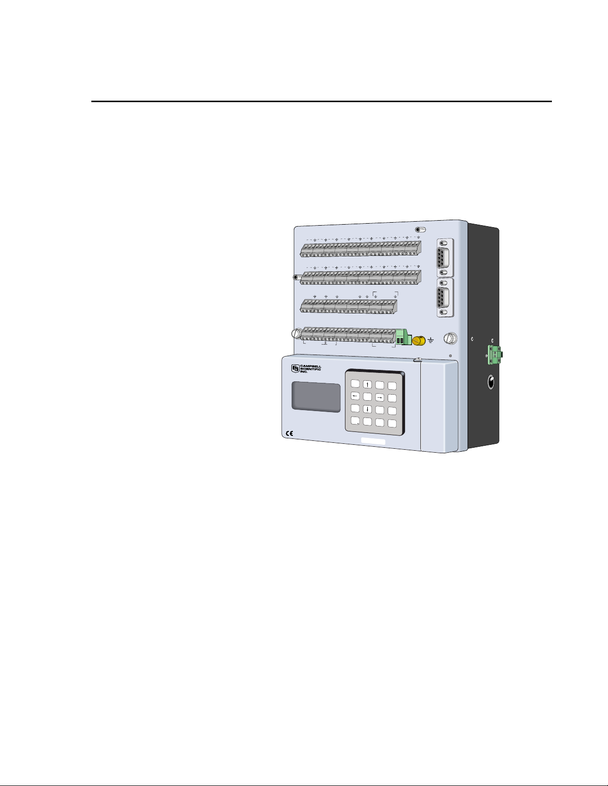
The CR5000 provides precision measurement capabilities in a rugged, battery-operated
package. The system makes measurements at a rate of up to 5,000 samples/second with
16-bit resolution. The CR5000 includes CPU, keyboard display, power supply, and analog
and digital inputs and outputs. The on-board, BASIC-like programming language includes
data processing and analysis routines. PC9000 Software provides program generation
and editing, data retrieval, and realtime monitoring.
19 20
17 18
15 16
13 14
11 12
910
56
34
12
SE
2
1
HL
HL
HL
DIFF
25
24
23
22
21
SE
12
11
H
L
H
L
H
DIFF
VX1
VX3
VX2
VX4
G
C6
C5
C7
G
C8
C
O
N
TR
O
L
I/O
PO
L
o
g
a
n
, U
ta
h
CR5000 MICROLOGGER
78
4
3
HL
28
27
26
14
13
HL
L
CAO1
CAO2
IX1
IX2
>2.0V
G
<0.8V
5V
5V
W
E
R
U
P
7
6
5
HL
HL
HL
34
33
32
31
30
29
17
16
15
L
H
HL
HL
CONTRO
IX3
IX4
IXR
P1
P1
C1C2C3
G
SDI-12
12V
G
SDM-C2
SDM-C1
SDM-C3
G
12V
P
O
W
'
,
_
A B C
D E F
H
m
P
gU
p
1
2
3
G H I
J K L
M N O
Graph/
char
4
5
6
P R S
T U V
W X Y
E
n
d
P
gD
n
7
8
9
- + (
* / )
< = >
D
el
Ins
ESC
0
SN:
E
HL
35
H
G
R
O
U
8
36
18
L
L I/O
C4
SW-12
SW-12
T
CURSOR
ALPHA
SHIFT
Spc Cap
BKSPC
$ Q Z
ENTER
HL
37
H
G
G
POWER IN
11 - 16 VDC
9
38
19
L
CAUTION
DC ONLY
12V
G
12V
MADE IN USA
10
HL
CS I/O
40
39
20
L
H
RS-232
COMPUTER
(OPTICALLY ISOLATED)
GROUND
LUG
pc card
status
FIGURE OV1-1. CR5000 Measurement and Control System
OV1. Physical Description
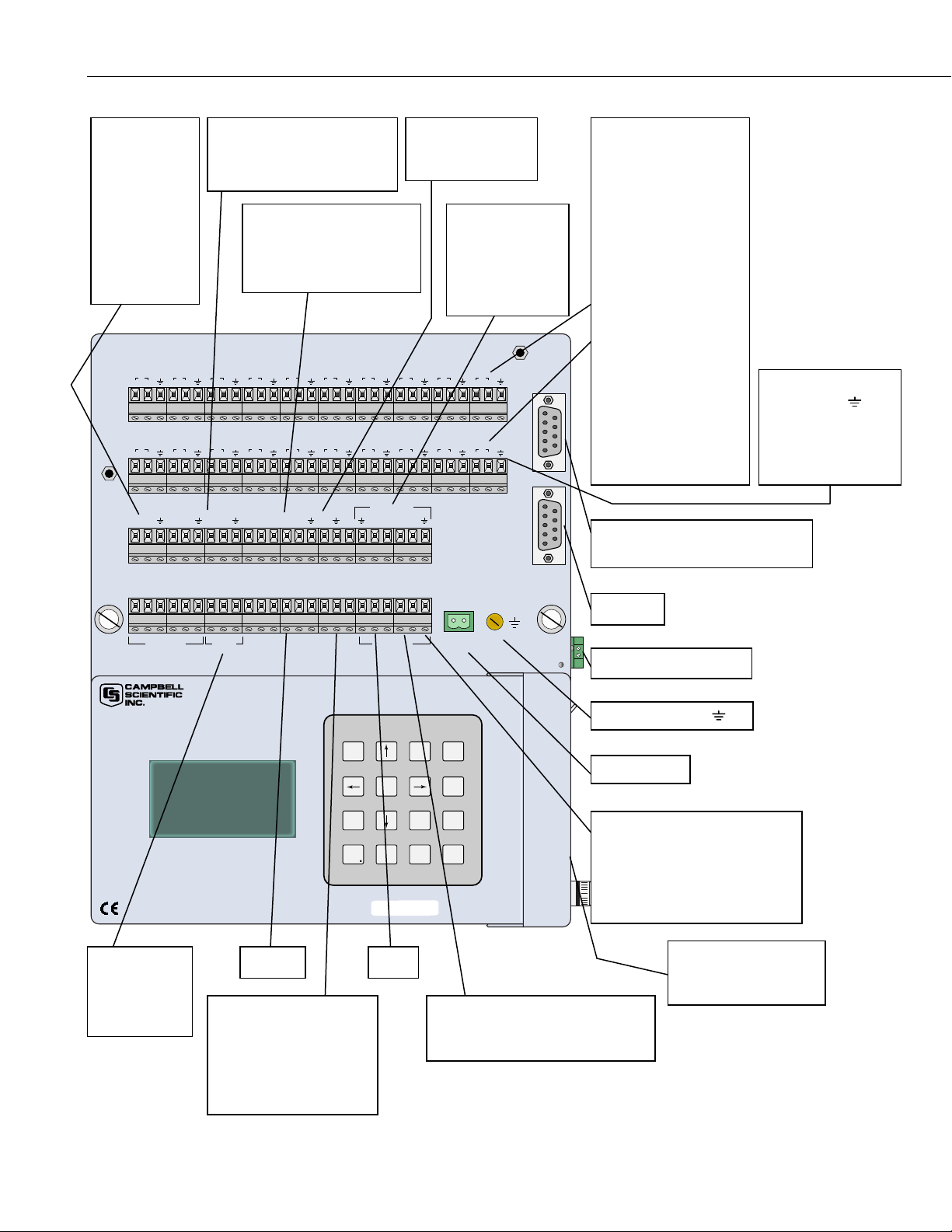
Figure OV1-2 shows the CR5000 panel and the associated program
instructions. Unless otherwise noted, they are measurement instructions
(Section 7).
OV1.1 Measurement Inputs
OV1.1.1 Analog Inputs
There are 20 differential or 40 single-ended inputs for measuring voltages up
to ±5 V. A thermistor installed in the wiring panel can be used to measure the
reference temperature for thermocouple measurements, and a heavy copper
grounding bar and connectors combine with the case design to reduce
temperature gradients for accurate thermocouple measurements. Resolution on
the most sensitive range is 0.67 µV
OV-1
Page 6
CR5000 Overview
t
SWITCHED
VOLTAGE
EXCITATION
(VX)
Excite
BrFull
BrFull6w
BrHalf
BrHalf3W
BrHalf4W
12
1
HL
21
11
HL
VX1
34
2
HL
22
23 24
12
HL
VX2
VX3
SE
DIFF
SE
DIFF
CONTINUOUS ANALOG
OUTPUTS (CAO)
ExciteCAO
SWITCHED CURRENT
EXCITATION (IX)
ExciteI
Resistance
56
78
910
3
4
HL
HL
25 26
27 28
13
14
HL
HL
VX4
CAO1
CAO2
IX1
IX2
IX3
5
HL
29 30
15
HL
IX4
11 12
6
HL
31 32
16
HL
IXR
P1
P2
13 14
7
HL
33 34
17
HL
PULSE INPUTS
PulseCount
PulseCountRese
15 16
17 18
8
HL
HL
35 36
37 38
18
HL
HL
CONTROL I/O
C1C2C3
C4
CONTROL I/O
PortGet
PortSet
ReadIO
TimerIO
WriteIO
19 20
9
10
HL
39 40
19
20
HL
COMPUTER RS-232
CS I/O
(OPTICALLY ISOLATED)
ANALOG INPUTS
Voltage
VoltDiff
VoltSE
Thermocouple
TCDiff
TCSE
Bridge measurements
(use VX)
BrFull
BrFull6W
BrHalf
BrHalf3W
BrHalf4W
Others
Resistance
PanelTemp
PeriodAvg
AM25T
SIGNAL
GROUND (
FOR
Analog
Pulse
Excitation
CS I/O
DSP4 (Data Tables and Output)
),
GC5C6C7C8G>2.0VG>0.8V5V5VGSDI-12
CONTROL I/O POWER
Logan, U
CR5000 MICROLOGGER
POWER UP
PowerOff
(program
control)
UP
tah
SDI-12 12 V
SDM CONNECTIONS
CS7500
CSAT3
SDMINT8
SDMSpeed
SDMTrigger
12VGSDM-C1
SDM-C2
SDM-C3G12VGSW-12
POWER OUT
'
_
,
A
Hm
1
I
H
G
J K
Graph/
char
4
S
R
T
P
End
7
(
- +
Del
SN:
SW-12
G
CAUTION
DC ONLY
G12V
POWER IN
11 - 16 VDC
GROUND
LUG
pc card
status
RS-232
CHARGER INPUT
GROUND LUG
F
C
E
B
D
CURSOR
PgUp
ALPHA
3
2
O
L
N
M
X
W
PgDn
< = >
ESC
6
Y
9
SHIFT
ap
pc C
S
BKSPC
Z
$ Q
ENTER
5
V
U
8
* / )
Ins
0
POWER IN
POWER GROUND (G),
FOR
5V
SW-12
12V
MADE IN USA
PCMCIA PC CARD
CardOut (Data Tables
and Output)
SWITCHED 12 VOLTS SW-12
PortSet
SW12
OV-2
FIGURE OV1-2. CR5000 Panel and Associated Instructions.
Page 7

OV1.1.2 Signal Grounds ( )
The Signal Grounds ( ) should be used as the reference for Single-ended
Analog inputs, Excitation returns, and sensor shield wires.
Signal returns from the CAO and Pulse channels should use the
located on the CAO and Pulse terminal strip to minimize current flow through
grounds on the analog terminal strips.
the
OV1.1.3 Power Grounds (G)
The Power Grounds (G) should be used as the returns for the 5V, SW12, 12V,
and C1-C8 outputs. Use of the G grounds for these outputs with potentially
large currents will minimize current flow through the analog section, which
can cause Single-ended voltage measurement errors.
OV1.1.4 Ground Lug
The large ground lug is used to connect a heavy gage wire to earth ground. A
good earth connection is necessary fix the ground potential of the datalogger
and to send to earth transients that come in on either the G or
are shunted to ground via the spark gaps protecting other inputs.
CR5000 Overview
terminals
terminals or
OV1.1.5 Power In
The G and 12V terminals on the unplugable Power In connector are for
connecting power from an external battery to the CR5000. These are the only
terminals that can be used to input battery power; the other 12V and SW-12V
terminals are out only. Power from this input will not charge internal CR5000
batteries. Power to charge the internal batteries (17-28 VDC or 18 VRMS AC)
must be connected to the charger input on the side of the LA battery back.
OV1.1.6 Switched 12 Volts SW-12
The SW-12 terminals provide an unregulated 12 volts that can be switched on
and off under program control.
OV1.1.7 Switched Voltage Excitation (VX)
Four switched excitation channels provide precision programmable voltages
within the ±5 Volt range for bridge measurements. Each analog output will
provide up to 50 mA between ±5 V.
OV1.1.8 Switched Current Excitation (IX)
Four Switched Current Excitation channels provide precision current
excitations programmable within ±2.5 mA for resistance or bridge
measurements.
OV1.1.9 Continuous Analog Outputs (CAO)
Two Continuous Analog Outputs (CAO) with individual outputs under
program control for proportional control (e.g., PID algorithm) and waveform
generation. Each analog output will provide up to 15 mA between ±5 V.
OV-3
Page 8

CR5000 Overview
OV1.1.10 Control I/O
OV1.1.11 Pulse Inputs
OV1.1.12 Power Up
There are 8 digital Input/Output channels (0 V low, 5 V high) for frequency
measurement, digital control, and triggering.
Two Pulse input channels can count pulses from high-level (5 V square wave),
switch closure, or low-level A/C signals.
The CR5000 allows shutting off power under program control. The Power Up
inputs allow an external signal to awaken the CR5000 from a powered down
state (PowerOff, Section 9). When the CR5000 is in this power off state the
ON Off switch is in the on position but the CR5000 is off. If the "<0.5 " input
is switched to ground or if the ">2" input has a voltage greater than 2 volts
applied, the CR5000 will awake, load and run the “run on power-up” program.
If the "< 0.5" input continues to be held at ground while the CR5000 is
powered on and goes through its 2-5 second initialization sequence, the
CR5000 will not run “run on power-up” program.
OV1.1.13 SDM Connections
The Synchronous Device for Measurement (SDM) connections C1,C2, and C3
along with the adjacent 12 volts and ground terminals are used to connect
SDM sensors and peripherals.
OV1.2 Communication and Data Storage
OV1.2.1 PCMCIA PC Card
One slot for a Type I/II/III PCMCIA card. The keyboard display is used to
check card status. The card must be powered down before removing it. The
card will be reactivated if not removed.
CAUTION
OV1.2.2 CS I/O
OV1.2.3 Computer RS-232
Removing a card while it is active can cause garbled data
and can actually damage the card. Do not switch off the
CR5000 power while the card is present and active.
A 9-pin serial I/O port supports CSI peripherals.
OV-4
RS-232 Port
Page 9

OV1.3 Power Supply and AC Adapter
The CR5000 has two base options the low profile without any power supply
and the lead acid battery power supply base. The low profile base requires an
external DC power source connected to the Power In terminal on the panel.
The battery base has a 7 amp hour battery with built in charging regulator and
includes an AC adapter for use where 120 VAC is available (18 VAC RMS
output). Charging power can also come from a 17-28 VDC input such as a
solar panel. The DCDC18R is available for stepping the voltage up from a
nominal 12 volt source (e.g., vehicle power supply) to the DC voltage required
for charging the internal battery.
OV2. Memory and Programming Concepts
OV2.1 Memory
The CR5000 has 2MB SRAM and 1MB Flash EEPROM. The operating
system and user programs are stored in the flash EEPROM. The memory that
is not used by the operating system and program is available for data storage.
The size of available memory may be seen in the status file. Additional data
storage is available by using a PCMCIA card in the built in card slot.
CR5000 Overview
OV2.2 Measurements, Processing, Data Storage
The CR5000 divides a program into two tasks. The measurement task
manipulates the measurement and control hardware on a rigidly timed
sequence. The processing task processes and stores the resulting
measurements and makes the decisions to actuate controls.
The measurement task stores raw Analog to Digital Converter (ADC) data
directly into memory. As soon as the data from a scan is in memory, the
processing task starts. There are at least two buffers allocated for this raw
ADC data (more under program control), thus the buffer from one scan can be
processed while the measurement task is filling another.
When a program is compiled, the measurement tasks are separated from the
processing tasks. When the program runs, the measurement tasks are
performed at a precise rate, ensuring that the measurement timing is exact and
invariant.
Processing Task: Measurement Task:
Digital I/O task
Read and writes to digital I/O ports
(ReadI/O, WriteI/O)
Processes measurements
Determines controls (port states) to set next scan
Stores data
Analog measurement and excitation sequence and
timing
Reads Pulse Counters
Reads Control Ports (GetPort)
Sets control ports (SetPort)
OV-5
Page 10

CR5000 Overview
OV2.3 Data Tables
The CR5000 can store individual measurements or it may use its extensive
processing capabilities to calculate averages, maxima, minima, histogams,
FFTs, etc., on periodic or conditional intervals. Data are stored in tables such
as listed in Table OV2-1. The values to output are selected when running the
program generator or when writing a datalogger program directly.
Table OV2-1. Typical Data Table
TOA4 StnName Temp
TIMESTAMP RECORD RefTemp_Avg TC_Avg(1) TC_Avg(2) TC_Avg(3) TC_Avg(4) TC_Avg(5) TC_Avg(6)
TS RN degC degC degC degC degC degC degC
Avg Avg Avg Avg Avg Avg Avg
1995-02-16 15:15:04.61 278822 31.08 24.23 25.12 26.8 24.14 24.47 23.76
1995-02-16 15:15:04.62 278823 31.07 24.23 25.13 26.82 24.15 24.45 23.8
1995-02-16 15:15:04.63 278824 31.07 24.2 25.09 26.8 24.11 24.45 23.75
1995-02-16 15:15:04.64 278825 31.07 24.21 25.1 26.77 24.13 24.39 23.76
OV3. PC9000 Application Software
PC9000 is a Windows™ application for use with the CR5000. The software
supports CR5000 program generation, real-time display of datalogger
measurements, graphing, and retrieval of data files.
OV3.1 Hardware and Software Requirements
The following computer resources are necessary:
• IBM PC, Portable or Desktop
• 8 Meg of Ram
• VGA Monitor
• Windows 95 or newer
• 30 Meg of Hard Drive Space for software
• 40 Meg of Hard Drive Space for data
• RS232 Serial Port
OV-6
The following computer resources are recommended:
• 16 Meg of Ram
• 33 MHz 486 or faster
• Mouse
OV3.2 PC9000 Installation
To install the PC9000 Software:
• Start Microsoft Windows
• Insert diskette 1 (marked 1 of 2) in a disk drive.
• From the Program Manager, select F
• Type (disk drive):\setup and press Enter e.g. a:\setup<Enter>
• The setup routine will prompt for disk 2.
ile menu and choose Run
Page 11

You may use the default directory of PC9000 or install the software in a
different directory. The directory will be created for you.
To abort the installation, type Ctrl-C or Break at any time.
OV3.3 PC9000 Software Overview
This overview points out the main PC9000 functions and where to find them.
PC9000 has extensive on-line help to guide the user in its operation, run
PC9000 to get the details. A CR5000 is not necessary to try out the
programming and real time display options; a demo uses canned data for
viewing. Without a CR5000, there are no communications with the
datalogger; operations such as downloading programs and retrieving data will
not function.
Figures OV3-1 and OV3-2 show the main PC9000 menus. The primary
functions of PC9000 are accessed from the File, Comm, Realtime, and
Analysis selections on the main menu (Figure OV3-1).
CR5000 Overview
OV-7
Page 12

CR5000 Overview
File Edit Realtime Analysis Tools Collect Display Windows Help
CommLink
Alarms List . . .
ield Monitor . . .
F
Virtual M
Virtual O
-Y Plotter . . .
X
istogram . . .
H
Fast Fourier T
Level Crossing Histogram . . .
et/Set Variable . . .
G
Display Data Graph 1 . . .
Display Data Graph 2
ID2000 . . . Ctrl + I
eter . . .
'Scope . . .
ransform . . .
Select S
Select P
Logger C
Logger Status . . .
D
ownload . . .
Save and Download
Logger F
Di
agnostics
Data Retrieval . . .
cheduled Data Retrieval . . .
S
eries Linked Station . . .
arallel Linked Station . . .
lock . . .
iles . . .
. . .
Realtime Display
& Graphing
Display Data in Tables Collected From CR5000.
Graphing requires no special processing of the data
and provides rapid feedback to the operator.
Collect data from CR5000
PC to CR5000
communications.
CR9000 Program Generator
000 Program Generator
CR5
CR9000 Program Editor . . .
CR5000 Program Editor . . .
Open W
Open Data Table I
Open D
Convert Binary to ASCII File . . .
P
Printer Setup . . .
D
File Manager . . .
E
Exit PC9000
iring Diagram . . .
ata File . . .
rint . . .
OS Shell . . .
xplorer . . .
nfo File . . .
Menu-driven Program Generation.
Direct Editing of Program
View/Edit Wiring Diagram & DataTable
Information (Created by Program Generator)
View Data Collected from CR5000
OV3-1. PC9000 Primary Functions
OV-8
Page 13

CR5000 Overview
File Edit Realtime Analysis Tools Collect Display Windows Help
Undo Ctrl + Z
Date & Time
Select All
Strip Remarks and Spaces Ctrl + S
Cut Ctrl + X
Copy Ctrl + C
Paste Ctrl + V
Delete
Delete Line Ctrl + Y
Wrap Text Ctrl + W
Go To Line . . .
Find Ctrl + F
Replace Ctrl + R
OV3-2. PC9000 Editing, Help, and User Preferences
Editing Options for
Active Windows
Colors . . .
Fonts . . .
Defaults . . .
Change fonts
and/or Colors for
Active Windows.
Tile Horizontal . . .
Tile Vertical . . .
Cascade . . .
Arrange Icons . . .
ork Area Setup . . .
W
List of Windows
PC9000 Help Contents . . .
earch PC9000 Help . . .
S
CRBasic Help Contents . . .
Search CR
Obtaining Technical Support . . .
A
bout PC9000 . . .
Software Versions . . .
Basic Help . . .
OV3.3.1 File
OV3.3.2 Edit
Program Generator
Guides the user through a series of menus to configure the measurement types:
thermocouple, voltage, bridge, pulse counting, frequency, and others. Creates
a CR5000 program, wiring diagram, output table, description, and
configuration file.
Program Editor
Create programs directly or edit those created by the program generator or
retrieved from the CR5000. Provides context-sensitive help for the CR5000's
BASIC-like language.
REALTIME
Virtual Meter
Updates up to five displays simultaneously. Choices include analog meter,
horizontal and vertical bars, independent scaling/offset, multiple alarms, and
rapid on-site calibration of sensors
OV-9
Page 14

CR5000 Overview
OV3.3.3 Analysis
OV3.3.4 Tools
OV3.3.5 Collect
Virtual Oscilloscope
Displays up to six channels. Time base variable from milliseconds to hours.
X-Y Plotter
Allows comparison of any two measurements in real time.
Data Graphing
Displays up to 16 fields simultaneously as strip charts or two multi-charts with
up to 8 traces each. Includes 2D/3D bars, line, log/linear, area, and scatter.
Line statistics available for max/min, best fit, mean, and standard deviation.
Handles files of unlimited size. Historical graphing requires no special
processing of the data and provides rapid feedback to the operator.
Control and Communications
Supports PC to CR5000 communications: clock read/set, status read, program
download, and program retrieval.
OV3.3.6 Display
OV3.3.7 Windows
OV3.3.8 Help
Collect data from CR5000 data tables
Configure the font and color scheme in an active window.
Size and arrange windows.
On-line help for PC9000 software.
OV-10
Page 15

OV4. Keyboard Display
CR5000 Overview
Power Up Screen
Press any key
CAMPBELL
SCIENTIFIC
CR5000 Datalogger
06/18/2000, 18:24:35
CPU: TRIG.CR5
Running.
for Main Menu
(except < >)
Data
Run/Stop Program
File
Status
Configure, Settings
Adjust contrast with < >
< lighter darker >
Real Time Tables
Real Time Custom
Final Storage Data
Reset Data Tables
Graph Setup
New
Edit
Copy
Delete
Run Options
Directory
Format
ROM Version : xxxx
OS Version : xxxx
OS Date : xxxx
OS Signature
Serial Number
Rev Board
Station Name : xxxx
Program Name : xxxxx
StartTime : xxxxx
Run Signature
DLD Signature
Battery : xxxx
Set Time/Date
Settings
Display
OV-11
Page 16

CR5000 Overview
OV4.1 Data Display
Data
Run/Stop Program
File
Status
Configure, Settings
Cursor to Data
and Press
Enter
Real Time Tables
Real Time Custom
Final Storage Data
Reset Data Table
Graph Setup
List of Data Tables created by
active program
List of Data Tables created by
active program
List of Data Tables created by
active program
OV-12
All Tables
List of Data Tables created by
active program
Graph Type: Scope
Scaler: Manual
Upper: 0.000000
Lower: 0.000000
Display Val Off
Display Max Off
Display Min Off
Page 17

OV4.1.1 Real Time Tables
List of Data Tables created by
active program. For Example,
Table1
Temps
Public
Cursor to desired
Table and press
Enter
Tref : 23.0234
TCTemp(1) : 19.6243
TCTemp(2) : 19.3429
TCTemp(3) : 21.2003
TCTemp(3) :
Flag(1) : -1.0000
Flag(2) : 0.00000
Flag(3) : 0.00000
Flag(4) : 0.00000
Public Table values
can be changed.
Cursor to value and
press Enter to edit
value.
CR5000 Overview
Tref : 23.0234
TCTemp(1) : 19.6243
TCTemp(2) : 19.3429
TCTemp(3) : 21.2003
TCTemp(3)
2
Flag(1) : -1.0000
Flag(2) : 0.00000
Flag(3) : 0.00000
Flag(4) : 0.00000
Press Graph/ Char
for Graph of
selected field
30.0 22.35
_____
___ ____
__
20.00
New values are displayed as they
are stored.
Scaler Manual
Press Ins for
Graph Setup
Upper: 30.000000
Lower: 20.000000
Display Val On
Display Max On
Display Min On
Graph Type Roll
OV-13
Page 18

CR5000 Overview
)
OV4.1.2 Setting up Real Time Custom Display
List of Data Tables created by
active program. For Example,
Table1
Temps
Public
Cursor to desired
Table and Press
Enter
Tref
TCTemp(1)
TCTemp(2)
TCTemp(3)
TCTemp(3
Flag(1)
Flag(2)
Flag(3)
Flag(4)
Cursor to position for next value
and Press Enter
Cursor to desired
Field and Press
Enter
TCTemp(3) : 24.9496
New values are displayed as they
are stored.
:
:
:
:
:
:
:
OV-14
Page 19

OV4.1.3 Final Storage Tables
_
List of Data Tables created by
active program. For Example:
Table1
Temps
CR5000 Overview
Cursor to desired
Table and Press
Enter
Use Hm (oldest), End (newest),
PgUp (older), PgDn (newer),
←, →, ↑
, and ↓ to move around
in data table.
TimeStamp Record Tref TC(1) TC(2) TC(3)
"2000-01-03 00:12:38" 0 21.934 22.8419
"2000-01-03 00:12:39" 1 24.1242 21.8619 21.9173 22.8364
"2000-01-03 00:12:40" 2 24.1242 21.8786 21.9229 22.8364
"2000-01-03 00:12:41" 3
"2000-01-03 00:12:42" 4
"2000-01-03 00:12:43" 5
"2000-01-03 00:12:44" 6
"2000-01-03 00:12:45" 7
"2000-01-03 00:12:46" 8
5 :2000-01-03 00:12:43
Tref TC(1)
24.1242 : 21.8786
24.1242 : 21.8786
24.1242 : 21.8675
21.8675
24.1242 : 21.8675
24.1242 : 21.8675
24.1242 : 21.8398
21.9173 22.8419
21.9173 22.8253
21.9118 22.8364
21.9173 22.8087
21.9173 22.8142
21.9395 22.8253
"2000-01-03 00:12:47" 9 24.1242 21.8176 21.9118 22.8308
"2000-01-03 00:12:48" 10 24.1242 21.8342 21.945 22.8364
"2000-01-03 00:12:49" 11 24.1242 21.8453 21.9506 22.8364
Press Ins for Jump To screen.
Go to Record:
Press Graph/ Char for
Graph of selected field.
←, →
Use
, PgUp, PgDn
to move cursor and
window of data graphed.
5
press Ins to edit
Table Size:
1000
Current Record:
759
30.0 21.87
______
______ _______
____ ___ ____
__
20.00
Press Ins for
Graph Setup
Scaler Manual
Upper: 30.000000
Lower: 20.000000
Display Val On
Display Max On
Display Min On
Graph Type Roll
OV-15
Page 20

CR5000 Overview
OV4.2 Run/Stop Program
PCCard Display
Data
Run/Stop Program
File
Status
Configure, Settings
Cursor to
PCCard and
Press Enter
Remove Card
Format Card
Table Status
Card Status
CPU:
List of Programs
No Program
CRD:
List of Programs
You may now
remove the Card.
CR5000 closes tables first.
All Card Data
Will be Lost!
Proceed?
Yes
No
List of Data Tables on card
created by active program
PC Card Status:
Battery OK
5Volt Card
WP Disabled
OV-16
Page 21

OV4.3 File Display
Data
Run/Stop Program
File
Status
Configure, Settings
Cursor to
File and
Press Enter
New
Edit
Copy
Delete
Run Options
Directory
Format
CR5000 Overview
New File Name:
CPU: .CR5
CRD: .CR5
CPU:
CRD:
Copy
From
To
Execute
List of files on
CPU or Card.
CPU: Program
No Program
CRD: Program
CPU:
All programs and other files
will be lost!
Proceed?
Yes List of Programs
No
OV-17
Page 22

CR5000 Overview
D
p
)
p
OV4.3.1 File: Edit
List of Program files on CPU: or
CRD: For Example:
CPU:
TCTEMP.CR5 0
RACE.CR5 0
Cursor to desired Program
and Press Enter
The Program Editor in PC9000 is recommended for writing and editing
datalogger programs. Changes in the field can be made with the keyboard
display.
Save Changes?
Yes
No
ESC
CR5000
' TCTemp.CR5
Public TREF,TC(3),FLAG(8)
D ataTable (Temps,1,1000)
Sample (1,TREF,IEEE4)
Sample (3,TC(),IEEE4)
Edit Directly or Cursor to first
character of line and Press
Enter
ENTER
Edit Instruction
Blank Line
Create Block
DataTable (Temps,1,1000)
DataTable (Temps,1,1000
Sample (1,TREF,IEEE4)
Sample (3,TC(),IEEE4)
EndTable
Press Ins
Edit Instruction parameters with
Cursor down to
highlight desired
block and press
Enter
INSERT
Instruction
Function
Blank Line
Block
Insert Off
arameter names and some pick lists:
DataTable
TableName
> Temps
TrigVar
1
Size
1000
Insert blank line
Block Commands
Copy
Cut
Delete
BeginProg
Scan(1,sec,3,0)
To insert a block created by this
operation, cursor to desired place in
rogram and press Ins.
OV-18
Page 23

OV4.4 Configure Display
Data
Run/Stop Program
File
Status
Configure, Settings
Cursor to
Configure,
Settings and
Press Enter
Set Time/Date
Settings
Display
CR5000 Overview
05/24/2000, 15:10:40
Year 2000
Month 5
Day 24
Hour 15
Minute 10
Set
Cancel
Security Enable
RS-232 Time Out: No
CR5000 Off
Light Dark
<- * ->
Enter Passwords:
Level 1:
Level 2:
Level 3:
click
Enter
Num
Password
Turn off display
Back Light
Contrast Adjust
Display Time Out: No, Yes (if yes)
Time out (min) 1
OV-19
Page 24

CR5000 Overview
OV5. Specifications
Electrical specifications are valid over a -25° to +50°C range unless otherwise specified; testing over -40° to +85°C available as
an option, excludes batteries. Non-condensing environment required. Yearly calibrations are recommended to maintain electrical specifications.
PROGRAM EXECUTION RATE
The CR5000 can measure one channel and store the
result in 500 µs; all 40 SE* channels can be measured
in 8 ms (5 kHz aggregate rate).
ANALOG INPUTS
DESCRIPTION: 20 DF* or 40 SE, individually
configured. Channel expansion provided through
AM16/32, AM416, and AM25T Multiplexers.
RANGES, RESOLUTION, AND TYPICAL INPUT
NOISE: Basic Resolution (Basic Res) is the A/D
resolution of a single conversion. Resolution of
DFM* with input reversal is half the Basic Res.
Noise values are for DFM with input reversal; noise
is greater with SEM.*
Input Basic 0 Int. 250 µs Int. 20/16.7 ms Int.
Rng (mV) Res (µV) (µV RMS) (µV RMS) (µV RMS)
±5000 167 70 60 30
±1000 33.3 30 12 6
±200 6.67 8 2.4 1.2
±50 1.67 3.0 0.8 0.3
±20 0.67 1.8 0.5 0.2
ACCURACY
MINIMUM TIME BETWEEN MEASUREMENTS:
COMMON MODE RANGE: ±5 V
DC COMMON MODE REJECTION: >100 dB with
NORMAL MODE REJECTION: 70 dB @ 60 Hz
SUSTAINED INPUT VOLTAGE WITHOUT DAMAGE:
INPUT CURRENT: ±2 nA typ., ±10 nA max. @ 50°C
INPUT RESISTANCE: 20 GΩ typical
ACCURACY OF INTERNAL THERMOCOUPLE
REFERENCE JUNCTION:
†
:
±(0.05% of Reading + Offset) 0° to 40°C
±(0.075% of Reading + Offset) -25° to 50°C
±(0.10% of Reading + Offset) -40° to 85°C
Offset for DFM w/input reversal =
Offset for DFM w/o input reversal =
Offset for SEM = 2Basic Res + 10 µV
Zero Integration: 125 µs
250 µs Integration: 475 µs
16.7 ms Integration: 19.9 ms
20 ms Integration: 23.2 ms
input reversal (>80 dB without input reversal)
when using 60 Hz rejection
±16 Vdc
±0.25°C, 0° to 40°C
±0.5°C, -25° to 50°C
±0.7°C, -40° to 85°C
Basic Res +1 µV
2Basic Res + 2 µV
ANALOG OUTPUTS
DESCRIPTION: 4 switched voltage; 4 switched cur-
rent; 2 continuous voltage; switched outputs active
only during measurements, one at a time.
RANGE: Voltage (current) outputs programmable
between ±5 V (±2.5 mA)
RESOLUTION: 1.2 mV (0.6 µA) for voltage (current)
outputs
ACCURACY: ±10 mV (±10 µA) for voltage (current)
outputs
CURRENT SOURCING: 50 mA for switched voltage;
15 mA for continuous
CURRENT SINKING: 50 mA for switched voltage;
5 mA for continuous (15 mA w/selectable option)
COMPLIANCE VOLTAGE: ±5 V for switched current
excitation
RESISTANCE MEASUREMENTS
Provides voltage ratio measurements of 4- and 6-wire
full bridges, and 2-, 3-, 4-wire half bridges. Direct
resistance measurements available with current excitation. Dual-polarity excitation is recommended.
VOLTAGE RATIO ACCURACY
excitation reversal and an excitation voltage of at
least 2000 mV.
±(0.04% Reading + Basic Res/4) 0° to 40°C
±(0.05% Reading + Basic Res/4) -25° to 50°C
±(0.06% Reading + Basic Res/4) -40° to 85°C
ACCURACY
†
WITH CURRENT EXCITATION:
Assumes input and excitation reversal, and an
excitation current, I
±(0.075% Reading + Basic Res/2I
±(0.10% Reading + Basic Res/2I
±(0.12% Reading + Basic Res/2I
†
: Assumes input and
, of at least 1 mA.
x
x
x
) 0° to 40°C
x
) -25° to 50°C
) -40° to 85°C
PERIOD AVERAGING MEASUREMENTS
DESCRIPTION: The average period for a single
cycle is determined by measuring the duration of a
specified number of cycles. Any of the 40 SE
analog inputs can be used; signal attenuation and
ac coupling may be required.
INPUT FREQUENCY RANGE:
Input Signal (peak to peak) Min. Max.
Rng (mV) Min. Max.
±5000 600 mV 10 V 2.5 µs 200 kHz
±1000 100 mV 2.0 V 5.0 µs 100 kHz
±200 4 mV 2.0 V 25 µs 20 kHz
1
Maximum signals must be centered around
datalogger ground.
RESOLUTION: 70 ns/number of cycles measured
ACCURACY: ±(0.03% of Reading + Resolution)
1
Pulse W. Freq
PULSE COUNTERS
DESCRIPTION: Two 16-bit inputs selectable for switch
closure, high frequency pulse, or low-level ac.
MAXIMUM COUNT: 4 x 10
SWITCH CLOSURE MODE:
Minimum Switch Closed Time: 5 ms
Minimum Switch Open Time: 6 ms
Maximum Bounce Time: 1 ms open without
being counted.
HIGH FREQUENCY PULSE MODE:
Maximum Input Frequency: 400 kHz
Maximum Input Voltage: ±20 V
Voltage Thresholds: Count upon transition
from below 1.5 V to above 3.5 V at low frequencies. Larger input transitions are required at high
frequencies because of 1.2 µs time constant filter.
LOW LEVEL AC MODE:
Internal ac coupling removes dc offsets up to
±0.5 V.
Input Hysteresis: 15 mV
Maximum ac Input Voltage: ±20 V
Minimum ac Input Voltage (sine wave):
(mV RMS) Range (Hz)
20 1.0 to 1000
200 0.5 to 10,000
1000 0.3 to 16,000
9
counts per scan
DIGITAL I/O PORTS
DESCRIPTION: 8 por ts selectable as binary inputs or
control outputs.
OUTPUT VOLTAGES (no load): high 5.0 V ±0.1 V;
low < 0.1 V
OUTPUT RESISTANCE: 330 Ω
INPUT STATE: high 3.0 to 5.3 V; low -0.3 to 0.8 V
INPUT RESISTANCE: 100 kΩ
EMI and ESD PROTECTION
The CR5000 is encased in metal and incorporates
EMI filtering on all inputs and outputs. Gas discharge
tubes provide robust ESD protection on all terminal
block inputs and outputs. The following European
standards apply.
EMC tested and conforms to BS EN61326:1998.
Details of performance criteria applied are available
upon request.
Warning: This is a Class A product. In a domestic
environment this product may cause radio interference
in which case the user may be required to correct the
interference at the user’s own expense.
CPU AND INTERFACE
PROCESSOR: Hitachi SH7034
MEMORY: Battery-backed SRAM provides 2 Mbytes
for data and operating system use with
128 kbytes reserved for program storage.
Expanded data storage with PCMCIA type I,
type II, or type III card.
DISPLAY: 8-line-by-21 character alphanumeric or
128 x 64 pixel graphic LCD display w/backlight.
SERIAL INTERFACES: Optically isolated RS-232
9-pin interface for computer or modem. CSI/O
9-pin interface for peripherals such as CSI
modems.
BAUD RATES: Selectable from 1,200 to 115,200 bps.
ASCII protocol is eight data bits, one start bit, one
stop bit, no parity.
CLOCK ACCURACY: ±1 minute per month
SYSTEM POWER REQUIREMENTS
VOLTAGE: 11 to 16 Vdc
TYPICAL CURRENT DRAIN: 400 µA software power
off; 1.5 mA sleep mode; 4.5 mA at 1 Hz (200 mA
at 5 kHz) sample rate.
INTERNAL BATTERIES: 7 Ahr rechargeable base
(optional); 1650 mAhr lithium battery for clock and
SRAM backup, 10 years of service typical, less at
high temperatures.
EXTERNAL BATTERIES: 11 to 16 Vdc; reverse
polarity protected.
PHYSICAL SPECIFICATIONS
SIZE: 9.8” x 8.3” x 4.5” (24.7 cm x 21.0 cm x 11.4 cm)
WEIGHT: 4.5 lbs (2.0 kg) with low-profile base;
Terminal strips extend 0.4” (1.0 cm).
12.2 lbs (5.5 kg) with rechargeable base
WARRANTY
Three years against defects in materials and
workmanship.
*SE(M): Single-Ended (Measurement)
*DF(M): Differential (Measurement)
†
Sensor and measurement noise not included.
We recommend that you confirm system
configuration and critical specifications with
Campbell Scientific before purchase.
OV-20
Page 25

This is a blank page.
Page 26

Campbell Scientific Companies
Campbell Scientific, Inc. (CSI)
815 West 1800 North
Logan, Utah 84321
UNITED STATES
www.campbellsci.com
info@campbellsci.com
Campbell Scientific Africa Pty. Ltd. (CSAf)
PO Box 2450
Somerset West 7129
SOUTH AFRICA
www.csafrica.co.za
cleroux@csafrica.co.za
Campbell Scientific Australia Pty. Ltd. (CSA)
PO Box 444
Thuringowa Central
QLD 4812 AUSTRALIA
www.campbellsci.com.au
info@campbellsci.com.au
Campbell Scientific do Brazil Ltda. (CSB)
Rua Luisa Crapsi Orsi, 15 Butantã
CEP: 005543-000 São Paulo SP BRAZIL
www.campbellsci.com.br
suporte@campbellsci.com.br
Campbell Scientific Canada Corp. (CSC)
11564 - 149th Street NW
Edmonton, Alberta T5M 1W7
CANADA
www.campbellsci.ca
dataloggers@campbellsci.ca
Campbell Scientific Ltd. (CSL)
Campbell Park
80 Hathern Road
Shepshed, Loughborough LE12 9GX
UNITED KINGDOM
www.campbellsci.co.uk
sales@campbellsci.co.uk
Campbell Scientific Ltd. (France)
Miniparc du Verger - Bat. H
1, rue de Terre Neuve - Les Ulis
91967 COURTABOEUF CEDEX
FRANCE
www.campbellsci.fr
campbell.scientific@wanadoo.fr
Campbell Scientific Spain, S. L.
Psg. Font 14, local 8
08013 Barcelona
SPAIN
www.campbellsci.es
info@campbellsci.es
Please visit www.campbellsci.com to obtain contact information for your local US or International representative.
 Loading...