

Page 1

r
w
CR200 Series Datalogge
Overvie
Revision: 3/07
Copyright © 2000-2006
Campbell Scientific, Inc.
Page 2

Page 3

CR200 Overview Table of Contents
PDF viewers note: These page numbers refer to the printed version of this document. Use
the Adobe Acrobat® bookmarks tab for links to specific sections.
CR200 Overview......................................................... OV-1
OV1. Physical Description ......................................................................OV-1
OV1.1 Measurement Inputs..............................................................OV-2
OV1.1.1 Analog Inputs ............................................................OV-2
OV1.1.2 Signal/Shield Grounds
OV1.1.3 Power Ground ............................................................OV-3
OV1.1.4 Ground Lug................................................................OV-3
OV1.1.5 Switched Voltage Excitation (VX)............................OV-3
OV1.1.6 Pulse Inputs................................................................OV-3
OV1.1.7 Control I/O.................................................................OV-3
OV1.1.8 Power In.....................................................................OV-3
OV1.1.9 Switched Battery........................................................OV-3
OV1.1.10 Power Supply and AC Adapter................................OV-3
OV1.2 Communication and Data Storage.........................................OV-4
OV1.2.1 RS-232........................................................................OV-4
OV1.2.2 Antenna......................................................................OV-5
OV2. Memory and Programming Concepts............................................OV-9
OV2.1 Memory.................................................................................OV-9
OV2.2 Measurements, Processing, Data Storage............................OV-10
OV2.3 Data Tables..........................................................................OV-10
OV2.4 PakBus Communication with the CR200............................OV-11
OV2.5 Serial ASCII Communication with the CR200...................OV-11
OV3. CR200 Setup using the Device Configurator Utility ...................OV-11
OV3.1 Power and Communication Connections to the CR200......OV-11
OV3.2 Using DevConfig to Set the PakBus Address.....................OV-12
OV3.3 CR206, CR211, and CR216 Radio Settings........................OV-14
OV3.3.1 Radio Hop Sequence................................................OV-14
OV3.3.2 Radio Address/Radio Net Address.......................... OV-14
OV3.3.3 Radio Power Mode..................................................OV-14
OV3.3.4 RF Protocol..............................................................OV-15
OV4. Quick Start Tutorial for Programming the CR200.......................OV-16
OV4.1 Software Products for the CR200 .......................................OV-16
OV4.1.1 Options for Creating CR200 Programs....................OV-16
OV4.2 Connections to the CR200 ..................................................OV-16
OV4.3 PC200W Software...............................................................OV-16
OV4.3.1 Creating a CR200 Program using Short Cut............OV-17
OV4.3.2 Configuring the Setup Tab.......................................OV-21
OV4.3.3 Synchronize the Clocks ...........................................OV-22
OV4.3.4 Send the Program.....................................................OV-22
OV4.3.5 Monitor Data Tables................................................OV-22
OV4.3.6 Collect Data.............................................................OV-22
OV4.3.7 View Data................................................................OV-23
OV4.5 Programming using the CRBasic Program Editor...............OV-24
OV5. Specifications...............................................................................OV-26
........................................OV-3
i
Page 4

CR200 Overview Table of Contents
Figures
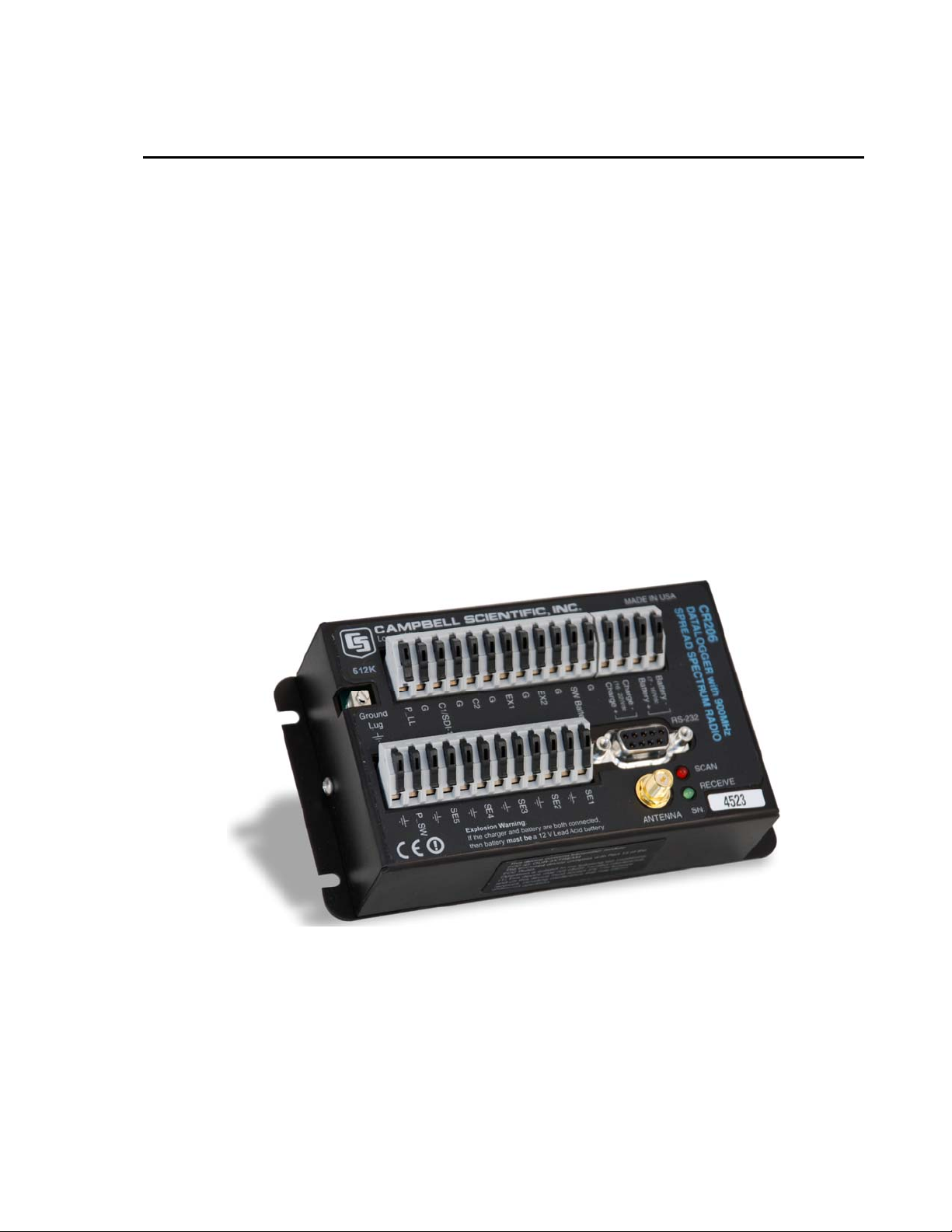
OV1-1 CR206 Datalogger with 900 MHz Spread Spectrum Radio....... OV-1
OV1-2 CR200 Panel and Associated Instructions.................................. OV-2
OV1-3. Serial Communication Interfaces............................................... OV-4
OV1-4. Some FCC Approved Antennas................................................. OV-8
OV1-5. Example COAX RPSMA-L Cable for Yagi or Omni Colinear.OV-9
OV1-6. Antenna Surge Protector............................................................OV-9
OV2-1. 512K on the datalogger label indicates the larger memory...... OV-10
OV3-1. Power and Communication Connections to the CR200........... OV-12
OV3-2. DevConfig Main Screen .......................................................... OV-13
OV3-3. Setting the PakBus Address..................................................... OV-13
Tables
OV1-1. Computer RS-232 Pin-Out......................................................... OV-4
OV2-1. Typical Data Table................................................................... OV-10
ii
Page 5
CR200 Overview
The CR200 datalogger provides versatile measurement capabilities in a low-cost, rugged,
battery-operated package. The CR200 includes CPU and analog and digital inputs and
outputs. The BASIC-like programming language includes data processing and analysis
routines.
The CR206, CR211, and CR216 combine the CR200 datalogger with a spread spectrum
radio for telemetering data. The different model numbers are for different spread spectrum
frequency ranges:
CR206 915 MHz U.S./Canada CR205 (Retired) 915 MHz U.S./Canada
CR211 922 MHz Australia/Israel CR210 (Retired) 922 MHz Australia/Israel
CR216 2.4 GHz Worldwide CR215 (Retired) 2.4 GHz Worldwide
The CR295 includes an additional 9-pin serial port and an instruction set that allows
communication with our TX312 HDR GOES satellite transmitter (see Appendix B).
Throughout this manual CR200 is used to refer to the datalogger that is the same
regardless of the model number.
FIGURE OV1-1. CR206 Datalogger with 900 MHz Spread Spectrum Radio
OV1. Physical Description
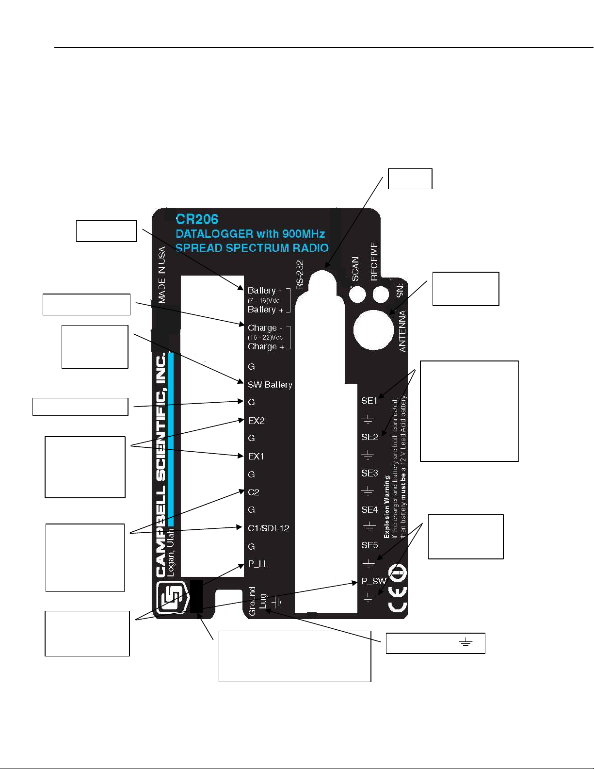
Figure OV1-2 shows the CR206 panel and the associated program instructions.
Unless otherwise noted, they are measurement instructions (Section 7).
OV-1
Page 6
CR200 Overview
y
OV1.1 Measurement Inputs
OV1.1.1 Analog Inputs
There are five single-ended inputs for measuring voltages from 0 to +2.5 V.
Resolution is 0.6 millivolts.
POWER IN
CHARGE INPUT
SWITCHED
BATTERY
SWBatt
POWER GROUNDS
SWITCHED
VOLTAGE
EXCITATION
ExDelSE
RS-232
ANTENNA
RadioPower
ANALOG INPUTS
VoltSE
ExDelSE (uses VX)
PeriodAvg
AnalogPortGet
AnalogPortSet
Other Measurements
Battery
CONTROL I/O
SDI12
PortGet
PortSet
SDI12Recorder
PULSE INPUTS
PulseCount
PulseCountReset
OV-2
512K
The 512K label indicates the larger
Serial Flash EEPROM. Dataloggers
without this label have a 128 kbyte
memor
FIGURE OV1-2. CR200 Panel and Associated Instructions.
instead of 512 kbytes.
GROUND LUG
SIGNAL AND
SHIELD
GROUNDS
Page 7

CR200 Overview
OV1.1.2 Signal/Shield Grounds
The terminals labeled
measurements and s
OV1.1.3 Power Gr
OV1.1.4 Ground L
OV1.1.5 Switched
OV1.1.6 Pulse Inp
ound (G)
The G terminals (Power Grounds) are used to carry return currents from other
devices powe
red by the SW Battery or battery and terminals.
ug
The earth ground lug is used to connect a heavy gage wire to earth ground. A
earth connection is necessary to fix the ground potential of the datalogger
good
o send to earth transients that come in on the terminals or are shunted to
and t
ground via the spark gaps protecting ot her inputs.
Voltage Excitation (VX)
Two switched excitation channels provide precision programmable voltag es
(+2.5 V + 5 V) for bridge measurem
to 20 mA at 2.5 V, 10 mA at 5 V.
uts
are used to connect the ground reference for
hield wires.
ents. Each analog output will provide up
OV1.1.7 Control I/
OV1.1.8 Power In
OV1.1.9 Switched
OV1.1.10 Power S
Two Pulse input channels can count pulses from high-level (5 V square wave),
h closure, or low-level A/C signals.
switc
O
There are two digital Input/Output channels (0 V low, 5 V high) for frequency
asurement, digital control, SDI-12 communication.
me
The Batt - and Batt + terminals are for connecting power from an external
battery to the CR200. The CR200 will operate on 7 to 16 VDC. These are the
only terminals that can be used to input battery power; the SW Battery terminal
is an output only. Power to charge a 12 V lead-acid battery (16-22 VDC) m
be connected to the Charge + and Charge – terminals.
ust
Battery
The SW Battery terminal provides an unregulated power from the battery that
can be switc
hed on and off under program control.
upply and AC Adapter
The CR200 does not have an internal power supply but d oe s have c o nnections
for an external battery and a buil
lead-acid battery from an externa
from a 16-22 VDC input such as a solar panel.
t-in charging regulator for charging a 12 V
l power source. Charging power can come
OV-3
Page 8
CR200 Overview
OV1.2 Commun
OV1.2.1 RS-232
ication and Data Storage
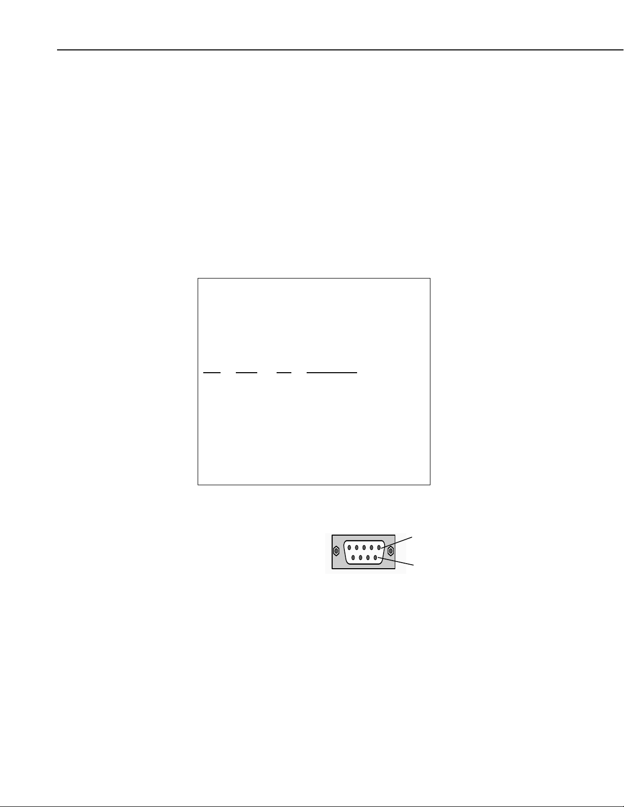
A computer can connect directly to the CR2
OV1-3). The CR200 RS-232 port is a DCE device. A limited version of the
RS-232 port is supported with no hardware fl ow contr ol . Tabl e OV 1- 1 gi v es a
brief description of each RS-232 pin.
The CR200 RS-232 port is not electrically isolated. Connection to an AC
powered computer may cause “ground loops” leading to measurement
problems.
Maximum input = ±25 V
Maximum Output = ±13 V
Typical Ou
TABLE OV1-1. Comp
ABR = Abbreviation for the function name
PIN
O
I = Signal Into the CR200 from a RS-23
PIN ABR I/O Description
tput = ±5.4 V
uter RS-232 Pin-Out
= Pin number
= Signal Out of the CR200 to a RS-232 device
00 through the RS-232 port (Figure
2 device
1 no connection
2 TX O asynchronous transmit
3 RX I asynchronous receive
4 no connection
5 GND ground
6 DSR O +5 V
7 no connection
8 CTS O V request to send +5
9 no connection
RS-232
Pin 1
FIGURE OV1-3. Serial Comm Interfaces unication
Pin 6
OV-4
Page 9

OV1.2.2 Antenna
CR200 Overview
Several antennas are offered to satisfy the needs for various base station and
remote station requirements. These antennas have been tested at an authorized
FCC open-field test site and are certified to be in compliance with FCC
emissions limits. All antennas (or antenna cables) have an SMA female
connector for connection to the CR200. The use of an unauthorized antenna
could cause transmitted field strengths in excess of FCC rules, interfere with
licensed services, and result in FCC sanctions against user. The CR205,
CR206, CR210, and CR211 use 900 MHz antennas, and the CR215 and CR216
use 2.4 GHz antennas.
NOTE
An FCC authorized antenna is a REQUIRED component. You
must pick one of the antennas listed below.
CSI Item Number Description
14310 0 dBd ANTENNA, 900 MHZ, OMNI ¼ WAVE WHIP,
RPSMA STRAIGHT, LINX, 3.2 inches long.
14204 0 dBd ANTENNA, 900 MHZ, OMNI ½ WAVE WHIP,
RPSMA RT ANGLE, ASTRON, 6.75 inches long.
14221 3 dBd ANTENNA, 900 MHZ, OMNI COLLINEAR,
ANTENEX FG9023, 24 inches tall, W/FM2 MOUNTS,
fits 1 in. to 2 in. O.D. mast (requires COAX RPSMA-L
or COAX NTN-L)
15970 1 dBd ANTENNA, 900 MHZ, INDOOR OMNI ½
WAVE DIPOLE, 10 ft. cable with SMA connector to fit
CR200 Series, window or wall mounted by sticky back,
4 inches wide.
14205 6 dBd ANTENNA, 900 MHZ, YAGI, LARSEN
YA6900 TYPE N-F, boom length 17.25 inches, longest
element 7.25 inches, W/MOUNTS, fits 1 in. to 2 in.
O.D. mast (requires COAX RPSMA-L or COAX NTNL)
14201 9 dBd ANTENNA, 900 MHZ, YAGI, MAXRAD
BMOY8905 TYPE N-F, boom length 21.4 inches,
longest element 6.4 inches, W/MOUNTS, fits 1 in. to 2
in. O.D. mast (requires COAX RPSMA-L or COAX
NTN-L)
16005 0 dBd ANTENNA, 2.4 GHz, OMNI ½ WAVE WHIP,
RPSMA RT ANGLE, LINX ANT-2.4-CW-RCT-RP,
4.5 inches long.
16755 13 dBd ANTENNA, 2.4 GHz, ENCLOSED YAGI,
allows vertical or horizontal polarization, MAXRAD
WISP24015PTNF, boom length 17 inches, diameter 3
inches, W/ END MOUNT to fit 1 to 2 in. O.D. mast
OV-5
Page 10
CR200 Overview
(requires either (1) COAX RPSMA-L for short runs or
(2) COAX NTN-L with Antenna Surge Protector Ki t )
COAX RPSMA-L LMR 195 ANTENNA CABLE, REVERSE POLARITY
SMA TO TYPE N MALE
COAX NTN-L RG8 ANTENNA CABLE, TYPE N MALE TO TYPE
N MALE CONNECTORS, REQUIRES 14462
14462 ANTENNA SURGE PROTECTOR KIT
FCC OET Bulletin No. 63 (October 1993)
Changing the antenna on a transmitter can significantly increase, or decrease,
the strength of the signal that is ultimately transmitted. Except for cable
locating equipment, the standards in Part 15 are not based solely on output
power but also take into account the antenna characteristics. Thus, a low
power transmitter that complies with the technical standards in Part 15 with a
particular antenna attached can exceed the Part 15 standards if a different
antenna is attached. Should this happen it could pose a serious interference
problem to authorized radio communications such as emergency, broadcast,
and air-traffic control communications.
CAUTION
In order to comply with the FCC RF exposure
requirements, the CR200 series may be used only with
approved antennas that have been tested with the onboard radio and a minimum separation distance of 20 cm
must be maintained from the antenna to any nearby
persons.
Read Appendix C of this manual for important FCC information.
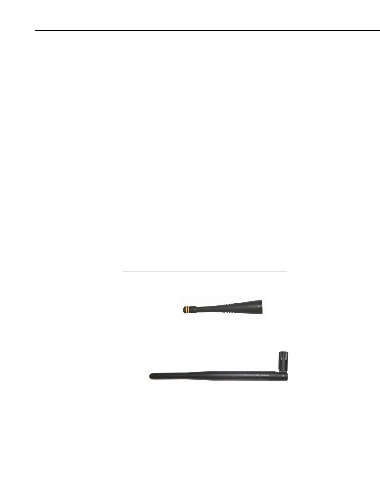
ITEM # 14310 900 MHZ OMNI ¼ WAVE WHIP 0 dBd
ITEM # 14204 900 MHZ OMNI ½ WAVE WHIP 0 dBd
OV-6
Page 11

CR200 Overview
ITEM # 14201 900 MHZ YAGI 9 dBd w/MOUNTS
ITEM #14205 900 MHz YAGI 6 dBd w/MOUNTS
ITEM # 14221 900 MHZ OMNI COLLINEAR 3 dBd w/MOU NTS
OV-7
Page 12

CR200 Overview
ITEM #15970 900 MHZ Indoor OMNI 1 dBd Window/Wall Mounted
ITEM #16005 2.4 GHz OMNI HALF WAVE WHIP 0 dBd
OV-8
ITEM #16755 2.4 GHz ENCLOSED YAGI, 13 dBd w/MOUNTS
FIGURE OV1-4. Some FCC Approved Antennas
Page 13

CR200 Overview
FIGURE OV1-5. Example COAX RPSMA-L Cable for Yagi or Omni
Colinear
FIGURE OV1-6. Antenna Surge Protector
OV2. Memory and Programming Concepts
OV2.1 Memory
The CR200 has 2K SRAM for communication buffers, calculations, and
variables, and 60K Flash EEPROM for the operating system and user program.
Dataloggers originally had a 128K Serial Flash EEPROM for data storage.
Campbell Scientific is increasing the data storage memory from 128 kbytes to
512 kbytes. Dataloggers with the increased memory have 512K on their label.
OV-9
Page 14

CR200 Overview
FIGURE OV2-1. 512K on the datalogger label indicates the larger memory.
OV2.2 Measurements, Processing, Data Storage
As a datalogger, the CR200 is programmed to measure the sensors and store
data in its EEPROM memory. Data are retrieved from the CR200 using a
computer and CSI software, e.g. LoggerNet.
A CR20X series datalogger with a spread spectrum radio (e.g. CR206) can also
function as a wireless interface between a sensor and a “master” PakBus
datalogger. In this configuration the CR200 measures the sensors and sends
the data to the master datalogger. Data are retrieved from the master, rather
than the CR20X.
OV2.3 Data Tables
The CR200 can store individual measurements or it may use its processing
capabilities to calculate averages, maxima, minima, etc., on periodic or
conditional intervals. Data are stored in tables such as listed in Table OV2-1.
The values to output are selected when running the program generator or when
writing a datalogger program directly.
TABLE OV2-1. Typical Data Table
TOA5 1 CR2XX v1.0 EXPLS4.CR2 45828 AvgTemp
TMSTAMP RECNBR SoilT_Avg(1) SoilT_Avg(2) SoilT_Avg(3) SoilT_Avg(4)
TS RN DegC DegC DegC DegC
Avg Avg Avg Avg
3/20/02 11:00 1 15.498 15.9926 18.516 19.5019
3/20/02 12:00 2 15.4996 15.9993 18.5069 19.502
3/20/02 13:00 3 15.4963 16.0042 18.4975 19.496
OV-10
Page 15

OV2.4 PakBus Communication with the CR200
The CR200 uses Pakbus to communicate with the computer and other Pakbus
devices. PakBus is a Campbell Scientific term for our packet-routing
communications protocol. Packets of information transmitted between PakBus
devices contain header information that is used to route the packets to their
final destination.
Every PakBus device needs a Pakbus address in order to receive, sen d, or route
packets. In a Pakbus network each device requires a unique address. The
CR200 is shipped with a default address of 1. The range of allowable addresses
is 1-3999.
A PakBus Networking Guide is available from the Campbell Scientific
website, which describes Pakbus and gives detailed examples for several
network configurations.
OV2.5 Serial ASCII Communication with the CR200
See Appendix A.
CR200 Overview
OV3. CR200 Setup using the Device Configurator
Utility
The Device Configurator Utility (DevConfig) ships with the LoggerNet, PC400
and PC200W software products, and is also available no-charge from the
Campbell Scientific website.
The Device Configuration Utility (DevConfig) sets up dataloggers and
peripherals before those devices are deployed in the field. Some key features
of DevConfig include:
• DevConfig only supports direct serial connections between the PC and
devices.
• DevConfig allows you to determine operating system types and versions.
• DevConfig provides a summary of the current configuration of a device
that can be shown on the screen and printed. This configuration can also
be saved to a file and used to restore the settings in the same or a
replacement device.
OV3.1 Power and Communication Connections to the CR200
To connect external power (7 – 16VDC) to the CR200, insert the positive lead
into the “Battery +”, followed by the negative lead into the “Battery-“
terminal, as shown in Figure OV3-1.
Connect the white serial cable (PN 10873, provided) be tween the port labeled
“RS232” on the CR200 and the serial port on the computer. For computers
that have only a USB port, a USB Serial Adaptor (PN 17394 or equivalent) is
required.
OV-11
Page 16

CR200 Overview
FIGURE OV3-1. Power and Communication Connections
to the CR200
OV3.2 Using DevConfig to Set the PakBus Address
The CR200 default PakBus address is 1. Unless the CR200 is used in a
network, there may be no need to change the Pakbus address, or any other
default setting. To change settings, the Device Configuration Utility
(DevConfig) is used, as described below.
To set the PakBus address, the CR200 must be powered up and connected to
the computer as described in Section OV 3.1.
Run the DevConfig Utility. The DevConfig window is divided into two main
sections: the device selection panel on the left, and tabs on the right. Select the
CR2XX device, and the COM port on the computer that will be used for
communications.
OV-12
Page 17

CR200 Overview
FIGURE OV3-2. DevConfig Main Screen
Click on the Connect button to establish communications. DevConfig
establishes communications with the CR200 and displays the scr e en shown in
Figure OV3-3.
FIGURE OV3-3. Setting the PakBus Address
OV-13
Page 18

CR200 Overview
OV3.3 CR206, CR211, and CR216 Radio Settings
To set the PakBus address, use the up and down arrows next to the “Pakbus
Address” box, or key in the desired number (e.g., 10) and click the Apply
button. Leave the PakBus address at 1 for use with the Quick Start Tutorial
(Section OV4). Click the Disconnect button to exit DevConfig.
The Spread Spectrum radios in the CR206, CR211, and CR216 and in the
RF400 have address, frequency, and power settings. These addresses are not
PakBus addresses but an address the radio encodes in its message. For two
radios to talk to each other the address and frequency settings must be the same
in both radios.
NOTE
In a PakBus network addresses and frequency settings in ALL
radios must be the same.
CR20X Radios are set up using the Deployment Tab as described in Section
OV3.3. The radio settings are described below.
OV3.3.1 Radio Hop Sequence
Spread Spectrum radios have a band of frequencies that they use. The radios
“hop” from one frequency to another within this band, allowing multiple sets
of radios to communicate at the same time without interfering with each other.
The “Radio Hop Sequence” determines the sequence in which the hops are
made. Radios must be set to the same “Radio Hop Sequence” in order to hear
each other (i.e., for the listening radio to synchronize with the transmitting
radio and hop to the same frequency at the same time). Set the same hop
sequence in all radios.
OV3.3.2 Radio Address/Radio Net Address
The “Radio Address” and “Radio Net Address” combined are sent as part of a
packet header with each message. Even if a radio is on the same hop sequence
and can hear another radio, it ignores the message unless that message has its
address in the header. Set the same “Radio Address” and “Radio Net
Address” in all radios.
OV-14
NOTE
RF400 Spread Spectrum Radios that communicate with the
CR206, CR211, or CR216 must also be set to the same Radio
Address and Radio Net Address. See the RF400 manual for
directions on setting these parameters in the RF400.
OV3.3.3 Radio Power Mode
The Radio Power Mode setting determines what portion of the time the radio is
powered up “listening” for incoming transmissions and how much power the
radio/datalogger consumes from its power supply.
RF_ON: Radio standby receive current <24 mA. The Radio Receiver is
always on. This provides the fastest response when the datalogger will be
interrogated but because of the current should only be used where an AC
backed power supply is available or the speed is absolutely necessary.
Page 19

CR200 Overview
RfpinEn: Radio standby receive current 0 mA.: For use as a wireless sensor
with a TD datalogger select RfpinEn for the Power Mode. This has the lowest
power requirement of all settings. The radio is controlled by the CR200
program. As a wireless sensor all transmissions are initiated by the CR200. The
radio is only powered for the transmission and a short time after while awaiting
the response from the master datalogger.
NOTE
In wireless sensor applications, the RF400 on the master
datalogger should be set to always on.
RF1_Sec: Radio standby receive current < 2 mA. The radio powers u p once
a second to listen for transmissions. The maximum response delay is 2 seconds.
RF8_Sec: Radio standby receive current < 0.4 mA. The radio powers up
every 8 seconds to listen for transmissions. The maximum response delay is 16
seconds.
RF1S_LH: Radio standby receive current < 2 mA. The radio powers up
once a second to listen for transmissions. When it initiates communication it
sends long header (>1 second) on messages. This is used only if the datalogger
will be initiating communications with SendGetData and other radios in the
system are using the 1 second standby mode. The long header insures other
radios in the network hear the message.
RF8S_LH: Radio standby receive current < 0.4 mA. The radio powers up
every 8 seconds to listen for transmissions. When it initiates communication it
sends long header (>8 seconds) on messages. This is used only if the
datalogger will be initiating communications with SendGetData and other
radios in the system are using the 8 second standby mode. The long header
insures other radios in the network hear the message.
After selecting the desired hop, address, and power mode settings, press “Save
Settings” to store the values to the radio.
OV3.3.4 RF Protocol
Identifies the radio protocol that will be used for the CR2xx. In order to be
compatible with other CR2xx and RF400 type devices, the default value of
transparent must be used. The following values are supported:
1. Transparent – This mode is compatible with older CR205, CR210, CR215,
2. PakBus – This mode can be used in networks invol vi n g
RF400, RF410, and RF415 operating systems.
RF401/RF411/RF416 ha rd ware or other, newer CR206/CR 21 1/ C R 216
devices and makes use of the retry capability inherent in the MaxStream
radios. This mode is not compatible with the older radios.
OV-15
Page 20

CR200 Overview
OV4. Quick Start Tutorial for Programming the
CR200
OV4.1 Software Products for the CR200
PC200W Starter Software supports a direct connection (RS232 cable or Spread
Spectrum radio) between the PC and the CR200, and includes Short Cut for
Windows (Short Cut) for creating CR200 programs. PC200W prov ides basic
tools for setting the datalogger’s clock, sending a program, monitoring sensors,
and manually collecting and viewing data. CR200 support was added to
PC200W in Version 3.0. PC200W is available at no charge from the Campbell
Scientific website.
PC400 Datalogger Support Software (mid-level software) supports a variety of
telecommunication options, manual data collection, and data display. PC400
includes Short Cut and the CRBasic Program Editor for creating CR200
programs. PC400 does not support combined communication options (e.g.,
phone-to-RF), PakBus® routing, or sche d ul ed dat a coll ect i o n.
LoggerNet Datalogger Support Software (full-featured software) supports
combined telecommunication options, data display, and scheduled data
collection. The software includes Short Cut and CRBasic for creating CR200
programs, and tools for configuring, trouble-shooting, and managing
datalogger networks.
OV4.1.1 Options for Creating CR200 Programs
1. Short Cut is a program generator that creates a datalogger program in four
easy steps, and a wiring diagram for the sensors. Short Cut supports the
majority of sensors sold by Campbell Scientific, and is recommended for
creating straightforward programs that measure the sensors and store data.
2. The CRBasic Editor is a program editor used to create more complex
CR200 programs. Short Cut generated programs can be imported into the
CRBasic Editor for adding instructions, or for functionality not supported
by Short Cut.
OV4.2 Connections to the CR200
Connect the CR200 to the 12V power supply and to the computer as described
in Section OV3.1.
OV4.3 PC200W Software
This Quick-Start tutorial prompts the user through the process of programming
the CR200, monitoring sensor measurements, collecting data, and viewing data
using the PC200W software. Before using PC200W, set the CR200 Pakbus
address to 1 as described in Section OV3.
When PC200W is first started, the EZSetup Wizard is launched. Click the
Next button and follow the prompts to select the CR200, the COM port on the
computer that will be used for communications, 9600 baud, and Pakbus
OV-16
Page 21

CR200 Overview
Address 1. When prompted with the option to Test Communications click
the Finish button.
To change a setting in the datalogger setup, select that datalogger from the
main window, and click the Edit button. If a datalogger was not added with
the Wizard, click the Add button to invoke the Wizard.
After exiting the EZSetup wizard, the Setup/Connect window appears, as
shown below. The Current Datalogger Profi l e, Datal o gg er C l ock, and
Datalogger Program features of PC200W are integrated into this window.
Tabs to the right are used to select the Monitor Values and Collect Data
windows. Buttons to the right of the tabs are used to run the Split, View, and
Short Cut applications.
Short Cut
OV4.3.1 Creating a CR200 Program using Short Cut
Objective: Every 10 seconds measure air temperature (°C) with a 109
Temperature Probe, and rainfall (mm) with a TE525WS rain gage. Every 1minute store average temperature, total rainfall, and minimum battery voltage.
Even if the 109 Temperature Probe and TE525WS Rain Gage sensors are not
available, the programming example can still be followed. Without a 109
probe connected the measurement result will be NAN; without a TE525WS
connected the measurement result will be 0.
Click on the Short Cut button to display the Home screen, as shown below.
OV-17
Page 22

CR200 Overview
Each of the four steps has a button with a ? for accessing Help. Use the Help
in conjunction with the steps outlined below:
Step 1: Create a New File
Step 1 is to open a new or existing file. From the Home page, click the New
button. Use the drop-down list box to select the CR200. Enter a 10 second
Scan Interval and click OK to complete Step 1.
Step 2: Select the Sensors
Step 2 is to select the sensors to be measured. From the Home page, click the
Sensors button. The Sensors worksheet is divided into two sections: the
Available sensors tree and the Selected sensors table, as shown below. The
sensors you want to measure are chosen from the Available sensors tree.
Double click on the Temperature application group to display the available
sensors. Double click on the 109 Temperature Probe sensor to add it the
selected sensors table. Click OK on the next screen to accept T109_C for the
measurement label, the DegC for the units.
Double click on the Meteorological application group. Double click on
Precipitation, and double click on the TE525 / TE525WS sensor to add it to
the selected sensors table. Click OK to accept Rain_mm for the measurement
label, and mm for the units.
OV-18
Page 23

CR200 Overview
Click on the Wiring Diagram tab to view the sensor wiring diagram, as shown
below. Wire the temperature probe and the TE525 rain gauge to the CR200 as
shown on the diagram. If you don’t have these sensors, a simple toggle switch
can be used to simulate the TE525. Without a 109 temperature probe
connected, the measurement result will be NAN (not a number).
Click the Sensors tab and the Home button to return to the Home page to
continue with Step 3.
OV-19
Page 24

CR200 Overview
Step 3: Output Processing
Step 3 is to define the output processing for the sensor measurements. From
the Home page, click the Output button.
The Output screen has a list of Selected Sensors on the left, and Output Tables
on the right. The default is for two Tables, Table1 and Table2. Both Tables
have a Store Every field and the drop-down list box that are used to set the
interval at which data will be stored.
The objective for this exercise calls for a one-minute output processing. To
remove Table2, Click on the Table2 tab to activate it, and click the Delete
Table button.
The Table Name field is the name that will be used for the Table in which the
output will be stored. Change the default Name of Table1 to OneMin, and
change the interval to 1 minute.
The Selected Sensors Table is provided on the left side of the screen. To add a
sensor measurement to the Output Table, highlight a measurement and click
one of the output buttons; e.g., Average.
Click the Default sensor (battery voltage) and double click the Minimum
button. Click the 109 temperature sensor and double click the Average button.
Click the TE525 rain gauge sensor and double click the Total button.
Click the Home button to continue with Step 4 to complete the program.
Step 4: Finish
OV-20
Step 4 is to finish the program. From the Home page, click the Finish button.
Type in CR200_QuickStart for the file name. Any errors the compiler may
have detected are displayed, along with the names of the files that were
created. The file C:\Campbellsci\SCWin\CR200_QuickStart.CR2 is the
program file that will be sent to the CR200, CR200_QuickStart.def is a
summary of the sensor wiring and measurement labels (click the Summary or
Page 25

CR200 Overview
Print buttons to view or print the file). Click the OK button and close Short
Cut.
OV4.3.2 Configuring the Setup Tab
From the Setup/Connect screen, click on the Connect button to establish
communications with the CR200. When communications have been
established, the text on the button will change to Disconnect.
Connect Button
OV-21
Page 26

CR200 Overview
OV4.3.3 Synchronize the Clocks
OV4.3.4 Send the Program
OV4.3.5 Monitor Data Tables
Click the Set Clock button to synchronize the datalogger’s clock with the
computer’s clock.
Click the Select and Send Program button. Navigate to the
C:\CampbellSci\SCWin folder and select the file CR200_QuickStart.CR2 and
click the Open button. A progress bar is displayed, followed by a message that
the program was successfully sent.
The Monitor Values window is used to display the current sensor measurement
values from the Public Table, and the most recent data from the OneMin Table.
Click on the Monitor Values tab. The Public Table is automatically selected
and displayed. To view the OneMin Table, click the Add button, select the
OneMin Table, and click the Paste button.
OV-22
OV4.3.6 Collect Data
Click on the Collect Data tab. From the Collect Data window you can choose
what data to collect, and where to store the retrieved data.
Click on the OneMin Table, with the Option New data from datalogger
selected. Click the Collect button and a dialog box appears, prompting for a
file name. Click the Save button to use the default file name
CR200_OneMin.dat. A progress bar, followed by the message Collection
Complete is displayed.
Page 27

CR200 Overview
OV4.3.7 View Data
To view the collected data, click on the View button (located in the upper right
hand corner of the main screen). Options are accessed by using the menus or
by selecting the toolbar icons. If you move and hold the mouse over a toolbar
icon for a few seconds, a brief description of that icon's function will appear.
To open a data file, click the Open file icon, and double click on the file
CR200_OneMin.dat in the PC200W folder. Click the Expand Tabs icon to
display the data in columns with column headings. To graph thermocouple
temperature, click on the data column with the heading Temp_C, then click the
Show Graph, 1 Y axis icon on the toolbar.
Open File Expand Tabs Show Graph
OV-23
Page 28

CR200 Overview
Close the graph and view screens, and close PC200W.
OV4.5 Programming using the CRBasic Program Editor
Users who are not familiar with the CRBasic programming language may find
Short Cut to be an excellent way to learn CRBasic. First create a program
using Short Cut, then open the file with CRBasic to see how Short Cut created
the program. The program file listed below is the Short Cut file
200_QuickStart.CR1 from the tutorial after being imported into the CRBasic
editor.
See Section 4 for information on the CRBasic programming.
'CR200 Series
'Created by SCWIN (2.2)
'Declare Variables and Units
Public Batt_Volt
Public T109_C
Public Rain_mm
Units Batt_Volt=Volts
Units T109_C=Deg C
Units Rain_mm=mm
'Define Data Tables
DataTable(OneMin,True,-1)
DataInterval(0,1,Min)
Minimum(1,Batt_Volt,False,False)
Average(1,T109_C,False)
Totalize(1,Rain_mm,False)
EndTable
OV-24
Page 29

'Main Program
BeginProg
Scan(10,Sec)
'Default Datalogger Battery Voltage measurement Batt_Volt:
Battery(Batt_Volt)
'109 Temperature Probe measurement T109_C:
Therm109(T109_C,1,1,1,1.0,0.0)
'TE525/TE525WS Rain Gauge measurement Rain_mm:
PulseCount(Rain_mm,P_SW,2,0,0.254,0)
'Call Data Tables and Store Data
CallTable(OneMin)
NextScan
EndProg
CR200 Overview
OV-25
Page 30

CR200 Overview
OV5. Specifications
ANALOG INPUTS; DIGITAL I/O
Channels SE1 to SE5 can be individually configured
for single-ended measurement or digital I/O.
SINGLE-ENDED MEASUREMENT (SE1 TO SE5):
Analog Input Range: 0 ≤ V < 2.5 Vdc
Measurement Resolution: 0.6 mV
Measurement Accuracy
Typical: ±(0.25% of reading + 1.2 mV offset)
over -40° to +50°C
Worst-case: ±(1% of reading + 2.4 mV offset)
over -40° to 50°C
DIGITAL I/O (SE1 TO SE5):
Input/Output High State: 2.1 to 3.3 Vdc
Input/Output Low State: <0.9 Vdc
Output High State: 3.3 V (no load)
Drive Current: 220 µA @ 2.7 Vdc
Maximum Input Volt
HALF BRIDGE MEASUREMENTS:
Accuracy: Relative to the excitation.
Using +2.5 Vdc excitation, is
±(0.06% of reading + 2.4 mV)
PERIOD AVERAGING (SE1 TO SE4):
Maximum Input Voltage: 4 Vdc
Frequency Range: 0 to 150 kHz
Voltage Threshold: counts cycles on transition
from <0.9 Vdc to >2.1 Vdc
EXCITATION CHANNELS (EX1 AND EX2):
Range: Programmable 0, 2.5, 5 Vdc, or
off (floating)
Accuracy: ±25 mV on +2.5 Vdc range, ±125 mV
on +5.0 Vdc range
Maximum Current: 25 mA on +2.5 Vdc range,
10 mA on +5.0 Vdc range
age: 4 Vdc
CONTROL PORTS (C1 AND C2)
DIGITAL I/O:
Voltage Level When Configured as Input:
<0.9 Vdc (low state) to >2.7 Vdc (high state)
Voltage Level When Configured as Output:
0 V (low state), 5 Vdc (high state) (no load)
Logic Level: TTL
Drive Current: 1.5 mA @ 4.5 V
SDI-12: SDI-12 sensors connect to C1
PULSE COUNTERS
SWITCH CLOSURE (P_SW):
Maximum Count Rate: 100 Hz
Minimum Switch Open Time: 5 ms
Minimum Switch Closed Time: 5 ms
Maximum Bounce Time: 4 ms
PULSE COUNT (P_SW, C1, AND C2):
Voltage Threshold: count on transition from
<0.9 V to >2.7 Vdc
Maximum Input Frequency: 1 kHz
Max Input Voltage: C1 & C2 (6.5 V), P_SW (4 Vdc)
LOW LEVEL AC (P_LL):
Voltage Threshold: <0.5 to >2 V
Minimum Input: 20 mV RMS
Maximum Frequency: 1 kHz
Maximum Input: ±20 V
Note: P_LL, C1, & C2 can be used for switch
closure using the battery voltage and a
20 kOhm pull-up resistor. If the dc offset is
>0.5 V, then AC coupling is required.
COMMUNICATIONS
SERIAL INTERFACE: Female RS-232 9-pin interface
for logger-to-PC communications
ON-BOARD SPREAD SPECTRUM RADIO:
Frequency: 915 MHz (CR206), 922 MHz (CR211),
or 2.4 GHz (CR216)
Transmission Range: 1 mile with 0 dBd ¼ wave
antenna (line-of-sight) and 900 MHz radios;
0.6 miles (1 km) with 0 dBd ½ wave antenna
(line-of-sight) and 2.4 GHz radio;
up to 10 miles with higher gain antenna
(line-of-sight)
RF4XX used as a base station radio
AVAILABLE RADIO TRANSMISSION MODES:
Always on, program controlled
Cycle Time: 1 or 8 s cycles; on for 100 ms every
period; checks for incoming communication
Scheduled Transmission Time: off until transmis-
sion time
P
®
AKBUS
packet switching network protocol
CLOCK ACCURACY
8.2 minutes/month @ -40° to +50°C; 1 minute/month
@ +25°C
CPU AND STORAGE
FINAL STORAGE: 512 kbyte Flash, data format
is 4 bytes per data point (table-based)
PROGRAM STORAGE: 6.5 kbyte Flash
FASTEST SCAN RATE: once per second
SWITCHED BATTERY (SW BATTERY)
Switched under program control; 300 mA minimum
current available
POWER
BATTERY VOLTAGE RANGE: 7 to 16 Vdc (can program
datalogger to measure internal battery voltage)
BATTERY: 12 Vdc sealed rechargeable with on-board
charging circuit. Alkaline cells, lithium, or other
non-rechargeable battery types may be connected
if the charging circuit is not used (i.e. nothing
connected to charging terminals).
CHARGER INPUT VOLTAGE: 16 to 22 Vdc
SHELF LIFE OF CLOCK’S BACKUP BATTERY:
5 years
CURRENT DRAIN (@12 V)
QUIESCENT CURRENT DRAIN:
No Radio or Radio Powered Off: ~0.2 mA
ACTIVE CURRENT DRAIN:
No radio ~3 mA
Radio receive ~20 mA (CR206, CR211),
~36 mA (CR216)
Radio transmit ~75 mA (CR206, CR211, CR216)
AVERAGE CONTINUOUS CURRENT DRAIN:
Radio always on ~20 mA (CR206, CR211),
~36 mA (CR216)
Radio in 1 s duty cycle ~2.2 mA (CR206,
CR211), ~4 mA (CR216)
Radio in 8 s duty cycle ~0.45 mA (CR206,
CR211), ~0.8 mA (CR216)
CE COMPLIANCE (as of 03/02)
CE COMPLIANT DATALOGGERS: CR200, CR206,
CR211, CR216
STANDARD(S) TO WHICH CONFORMITY IS
DECLARED: IEC61326:2002
EMI AND ESD PROTECTION
IMMUNITY: Meets or exceeds following standards:
ESD: per IEC 1000-4-2; ±8 kV air, ±4 kV contact
discharge
RF: per IEC 1000-4-3; 3 V/m, 80-1000 MHz
EFT: per IEC 1000-4-4; 1 kV power, 500 V I/O
Surge: per IEC 1000-4-5; 1 kV power and I/O
Conducted: per IEC 1000-4-6; 3 V 150 kHz-80 MHz
Emissions and immunity performance criteria available
on request.
PHYSICAL
CASE DESCRIPTION: Aluminum with spring-loaded
terminals
DIMENSIONS (including terminals): 5.5” x 3” x 2”
(14.0 x 17.6 x 5.1 cm)
WEIGHT:
CR200 or CR295: 8.5 oz (242 g)
CR206, CR211, or CR216: 9.5 oz (271 g)
CUSTOM CASE: available for OEM applications;
contact Campbell Scientific
WARRANTY
One year covering parts and labor.
OV-26
Page 31

This is a blank page.
Page 32

Campbell Scientific Companies
Campbell Scientific, Inc. (CSI)
815 West 1800 North
Logan, Utah 84321
UNITED STATES
www.campbellsci.com
info@campbellsci.com
Campbell Scientific Africa Pty. Ltd. (CSAf)
PO Box 2450
Somerset West 7129
SOUTH AFRICA
www.csafrica.co.za
cleroux@csafrica.co.za
Campbell Scientific Australia Pty. Ltd. (CSA)
PO Box 444
Thuringowa Central
QLD 4812 AUSTRALIA
www.campbellsci.com.au
info@campbellsci.com.au
Campbell Scientific do Brazil Ltda. (CSB)
Rua Luisa Crapsi Orsi, 15 Butantã
CEP: 005543-000 São Paulo SP BRAZIL
www.campbellsci.com.br
suporte@campbellsci.com.br
Campbell Scientific Canada Corp. (CSC)
11564 - 149th Street NW
Edmonton, Alberta T5M 1W7
CANADA
www.campbellsci.ca
dataloggers@campbellsci.ca
Campbell Scientific Ltd. (CSL)
Campbell Park
80 Hathern Road
Shepshed, Loughborough LE12 9GX
UNITED KINGDOM
www.campbellsci.co.uk
sales@campbellsci.co.uk
Campbell Scientific Ltd. (France)
Miniparc du Verger - Bat. H
1, rue de Terre Neuve - Les Ulis
91967 COURTABOEUF CEDEX
FRANCE
www.campbellsci.fr
campbell.scientific@wanadoo.fr
Campbell Scientific Spain, S. L.
Psg. Font 14, local 8
08013 Barcelona
SPAIN
www.campbellsci.es
info@campbellsci.es
Please visit www.campbellsci.com to obtain contact information for your local US or International representative.
 Loading...