

Page 1
INSTRUCTION MANUAL
CMP3 Pyranometer
Copyright © 2006- 2016
Campbell Scientific, Inc.
Revision: 2/16
Page 2

Page 3

Limited Warranty
“Products manufactured by CSI are warranted by CSI to be free from defects
in materials and workmanship under normal use and service for twelve months
from the date of shipment unless otherwise specified in the corresponding
product manual. (Product manuals are available for review online at
www.campbellsci.com.) Products not manufactured by CSI, but that are resold
by CSI, are warranted only to the limits extended by the original manufacturer.
Batteries, fine-wire thermocouples, desiccant, and other consumables have no
warranty. CSI’s obligation under this warranty is limited to repairing or
replacing (at CSI’s option) defective Products, which shall be the sole and
exclusive remedy under this warranty. The Customer assumes all costs of
removing, reinstalling, and shipping defective Products to CSI. CSI will return
such Products by surface carrier prepaid within the continental United States of
America. To all other locations, CSI will return such Products best way CIP
(port of entry) per Incoterms ® 2010. This warranty shall not apply to any
Products which have been subjected to modification, misuse, neglect, improper
service, accidents of nature, or shipping damage. This warranty is in lieu of all
other warranties, expressed or implied. The warranty for installation services
performed by CSI such as programming to customer specifications, electrical
connections to Products manufactured by CSI, and Product specific training, is
part of CSI's product warranty. CSI EXPRESSLY DISCLAIMS AND
EXCLUDES ANY IMPLIED WARRANTIES OF MERCHANTABILITY
OR FITNESS FOR A PARTICULAR PURPOSE. CSI hereby disclaims,
to the fullest extent allowed by applicable law, any and all warranties and
conditions with respect to the Products, whether express, implied or
statutory, other than those expressly provided herein.”
Page 4

Assistance
Products may not be returned without prior authorization. The following
contact information is for US and international customers residing in countries
served by Campbell Scientific, Inc. directly. Affiliate companies handle
repairs for customers within their territories. Please visit
www.campbellsci.com to determine which Campbell Scientific company serves
your country.
To obtain a Returned Materials Authorization (RMA), contact CAMPBELL
SCIENTIFIC, INC., phone (435) 227-9000. After an application engineer
determines the nature of the problem, an RMA number will be issued. Please
write this number clearly on the outside of the shipping container. Campbell
Scientific’s shipping address is:
CAMPBELL SCIENTIFIC, INC.
RMA#_____
815 West 1800 North
Logan, Utah 84321-1784
For all returns, the customer must fill out a “Statement of Product Cleanliness
and Decontamination” form and comply with the requirements specified in it.
The form is available from our website at www.campbellsci.com/repair. A
completed form must be either emailed to repair@campbellsci.com or faxed to
(435) 227-9106. Campbell Scientific is unable to process any returns until we
receive this form. If the form is not received within three days of product
receipt or is incomplete, the product will be returned to the customer at the
customer’s expense. Campbell Scientific reserves the right to refuse service on
products that were exposed to contaminants that may cause health or safety
concerns for our employees.
Page 5

Safety
DANGER — MANY HAZARDS ARE ASSOCIATED WITH INSTALLING, USING, MAINTAINING, AND WORKING ON OR AROUND
TRIPODS, TOWERS, AND ANY ATTACHMENTS TO TRIPODS AND TOWERS SUCH AS SENSORS, CROSSARMS, ENCLOSURES,
ANTENNAS, ETC. FAILURE TO PROPERLY AND COMPLETELY ASSEMBLE, INSTALL, OPERATE, USE, AND MAINTAIN TRIPODS,
TOWERS, AND ATTACHMENTS, AND FAILURE TO HEED WARNINGS, INCREASES THE RISK OF DEATH, ACCIDENT, SERIOUS
INJURY, PROPERTY DAMAGE, AND PRODUCT FAILURE. TAKE ALL REASONABLE PRECAUTIONS TO AVOID THESE HAZARDS.
CHECK WITH YOUR ORGANIZATION'S SAFETY COORDINATOR (OR POLICY) FOR PROCEDURES AND REQUIRED PROTECTIVE
EQUIPMENT PRIOR TO PERFORMING ANY WORK.
Use tripods, towers, and attachments to tripods and towers only for purposes for which they are designed. Do not exceed design
limits. Be familiar and comply with all instructions provided in product manuals. Manuals are available at www.campbellsci.com or
by telephoning (435) 227-9000 (USA). You are responsible for conformance with governing codes and regulations, including safety
regulations, and the integrity and location of structures or land to which towers, tripods, and any attachments are attached. Installation
sites should be evaluated and approved by a qualified engineer. If questions or concerns arise regarding installation, use, or
maintenance of tripods, towers, attachments, or electrical connections, consult with a licensed and qualified engineer or electrician.
General
• Prior to performing site or installation work, obtain required approvals and permits. Comply
with all governing structure-height regulations, such as those of the FAA in the USA.
• Use only qualified personnel for installation, use, and maintenance of tripods and towers, and
any attachments to tripods and towers. The use of licensed and qualified contractors is highly
recommended.
• Read all applicable instructions carefully and understand procedures thoroughly before
beginning work.
• Wear a hardhat and eye protection, and take other appropriate safety precautions while
working on or around tripods and towers.
• Do not climb tripods or towers at any time, and prohibit climbing by other persons. Take
reasonable precautions to secure tripod and tower sites from trespassers.
• Use only manufacturer recommended parts, materials, and tools.
Utility and Electrical
• You can be killed or sustain serious bodily injury if the tripod, tower, or attachments you are
installing, constructing, using, or maintaining, or a tool, stake, or anchor, come in contact with
overhead or underground utility lines.
• Maintain a distance of at least one-and-one-half times structure height, 20 feet, or the distance
required by applicable law, whichever is greater, between overhead utility lines and the
structure (tripod, tower, attachments, or tools).
• Prior to performing site or installation work, inform all utility companies and have all
underground utilities marked.
• Comply with all electrical codes. Electrical equipment and related grounding devices should
be installed by a licensed and qualified electrician.
Elevated Work and Weather
• Exercise extreme caution when performing elevated work.
• Use appropriate equipment and safety practices.
• During installation and maintenance, keep tower and tripod sites clear of un-trained or non-
essential personnel. Take precautions to prevent elevated tools and objects from dropping.
• Do not perform any work in inclement weather, including wind, rain, snow, lightning, etc.
Maintenance
• Periodically (at least yearly) check for wear and damage, including corrosion, stress cracks,
frayed cables, loose cable clamps, cable tightness, etc. and take necessary corrective actions.
• Periodically (at least yearly) check electrical ground connections.
WHILE EVERY ATTEMPT IS MADE TO EMBODY THE HIGHEST DEGREE OF SAFETY IN ALL CAMPBELL SCIENTIFIC PRODUCTS,
THE CUSTOMER ASSUMES ALL RISK FROM ANY INJURY RESULTING FROM IMPROPER INSTALLATION, USE, OR
MAINTENANCE OF TRIPODS, TOWERS, OR ATTACHMENTS TO TRIPODS AND TOWERS SUCH AS SENSORS, CROSSARMS,
ENCLOSURES, ANTENNAS, ETC.
Page 6

Page 7

Table of Contents
PDF viewers: These page numbers refer to the printed version of this document. Use the
PDF reader bookmarks tab for links to specific sections.
1. Introduction ................................................................ 1
2. Precautions ................................................................ 1
3. Initial Inspection ......................................................... 1
3.1 Ships With ............................................................................................ 1
3.2 Calibration Certificate .......................................................................... 1
4. QuickStart ................................................................... 2
5. Overview ..................................................................... 4
6. Specifications ............................................................. 5
7. Installation .................................................................. 6
7.1 Siting .................................................................................................... 6
7.2 Mounting to an Instrument Mount ....................................................... 7
7.2.1 Required Tools .............................................................................. 7
7.2.2 Mounting Procedure...................................................................... 7
7.2.2.1 CM225 Solar Sensor Mounting Stand ................................ 7
7.2.2.2 015ARM ........................................................................... 10
7.3 Wiring to the Datalogger .................................................................... 11
7.4 Programming ...................................................................................... 12
7.4.1 Input Range ................................................................................. 13
7.4.2 Multiplier .................................................................................... 13
7.4.3 Offset .......................................................................................... 14
7.4.4 Output Format Considerations .................................................... 14
8. Maintenance and Troubleshooting ......................... 14
8.1 Maintenance/Recalibrations ............................................................... 14
8.2 Troubleshooting ................................................................................. 15
Appendices
A. Importing Short Cut Code Into CRBasic Editor ... A-1
B. Example Program ................................................... B-1
B.1 CR1000 Example Program .............................................................. B-1
i
Page 8

Table of Contents
Figures
7-1. Pyranometer installation ...................................................................... 6
7-2. CMP3 Schematic ............................................................................... 11
Tables
7-1. Wire Color, Function, and Datalogger Connection for
Differential Measurements ............................................................. 11
7-2. Wire Color, Function, and Datalogger Connection for
Single-Ended Measurements ......................................................... 12
7-3. Multipliers Required for Flux Density and Total Fluxes ................... 13
CRBasic Example
B-1. CR1000 Example Program .............................................................. B-1
ii
Page 9

NOTE
CMP3 Pyranometer
1. Introduction
The CMP3 is an ISO-second-class pyranometer that monitors solar radiation
for the full solar spectrum range. It produces a millivolt signal that is measured
directly by a Campbell Scientific datalogger. The CMP3 can provide solar
radiation measurements for a variety of meteorological applications.
This manual provides information only for CRBasic dataloggers.
It is also compatible with many of our retired Edlog dataloggers.
For Edlog datalogger support, see an older manual at
www.campbellsci.com\old-manuals or contact a Campbell
Scientific application engineer for assistance.
2. Precautions
• READ AND UNDERSTAND the Safety section at the front of this
manual.
• CMP3 pyranometer is rugged, but it should be handled as precision
scientific instruments.
• Care should be taken when opening the shipping package to not damage or
cut the cable jacket. If damage to the cable is suspected, consult with a
Campbell Scientific applications engineer.
3. Initial Inspection
• Check the contents of the shipment. If there is a shortage (see Section 3.1,
Ships With
during transport, immediately file a claim with the carrier and contact
Campbell Scientific to facilitate repair or replacement.
• The model number and cable length are printed on a label at the
connection end of the cable. Check this information against the shipping
documents to ensure the correct product and cable length are received.
3.1 Ships With
(2) Bolts for mounting from original manufacturer
(1) Instruction manual from original manufacturer
(1) Sun shield from original manufacturer
(2) Nylon washers from original manufacturer
(p. 1)), contact Campbell Scientific. If any damage has occurred
3.2 Calibration Certificate
Each pyranometer is shipped with an instruction manual provided by Kipp &
Zonen that contains information concerning its construction, spectral
sensitivity, cosine response, and a simple sensor check out procedure. Included
with the sensor and manual is a calibration certificate with the sensor
sensitivity value and serial number.
1
Page 10

CMP3 Pyranometer
NOTE
4. QuickStart
Cross check this serial number against the serial number on your
pyranometer to ensure that the given sensitivity value corresponds
to your sensor.
Short Cut is an easy way to program your datalogger to measure the
pyranometer and assign datalogger wiring terminals. Short Cut is available as a
download on www.campbellsci.com and the ResourceDVD. It is included in
installations of LoggerNet, PC200W, PC400, or RTDAQ.
Use the following procedure to get started.
1. Open Short Cut. Click New Program.
2
Page 11

CMP3 Pyranometer
2. Select Datalogger Model and Scan Interval (default of 5 seconds is OK
for most applications). Click Next.
3. Under the Available Sensors and Devices list, select Sensors |
Meteorological | Solar Radiation folder. Select CMP3/CMP6/CMP11
Pyranometer. Click to move the selection to the Selected device
window. Default units are kW/m2 for flux density units and kJ/m2 for total
flux. These can be changed by clicking the Flux Density and Total Flux
boxes and selecting different values. A sensitivity value needs to be
entered. This value is unique to each sensor and is listed on the calibration
sheet that is included with the sensor.
3
Page 12
CMP3 Pyranometer
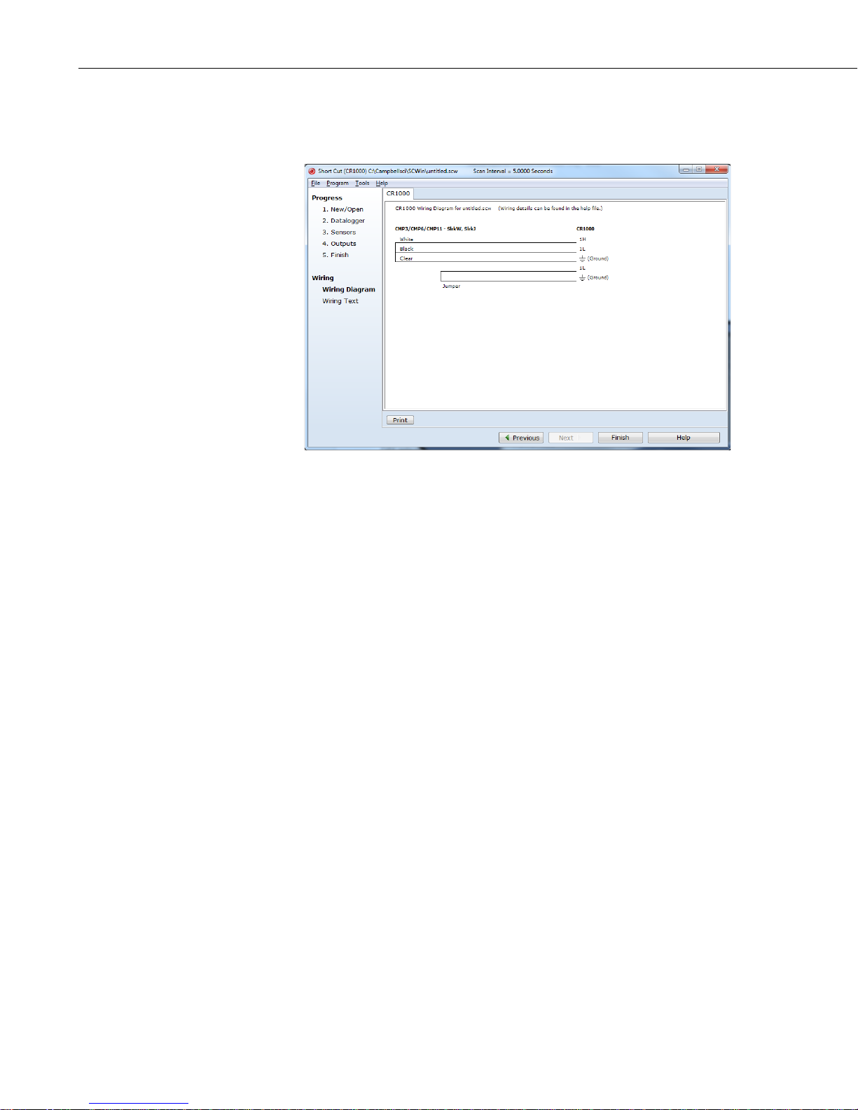
4. After selecting the sensitivity values, click Wiring Diagram to see how
the sensor is to be wired to the datalogger. The wiring diagram can be
printed now or after more sensors are added.
5. Overview
5. Select any other sensors you have, then finish the remaining Short Cut
steps to complete the program. The remaining steps are outlined in Short
Cut Help, which is accessed by clicking on Help | Contents |
Programming Steps.
6. If LoggerNet, PC400, RTDAQ, or PC200W is running on your PC, and the
PC to datalogger connection is active, you can click Finish in Short Cut
and you will be prompted to send the program just created to the
datalogger.
7. If the sensor is connected to the datalogger, as shown in the wiring
diagram in step 4, check the output of the sensor in the datalogger support
software data display to make sure it is making reasonable measurements.
This manual provides information for interfacing the CMP3 Pyranometer to
various models of Campbell Scientific dataloggers. The CMP3 is manufactured
by Kipp & Zonen and then cabled by Campbell Scientific. Cable length is user
specified.
The CMP3 pyranometer is designed for continuous outdoor use. Due to its flat
spectral sensitivity from 300 to 2800 nm, it can be used in natural sunlight,
under plant canopies, in green houses or buildings, and inverted to measure
reflected solar radiation. Two CMP3s can be used in combination to measure
albedo. The CMP3 can also be used to measure most types of artificial light
(Xenon lamps, Halogen lamps, etc.).
The CMP3 pyranometer consists of a thermopile sensor, housing, dome, and
cable. The thermopile is coated with a black absorbent coating. The paint
absorbs the radiation and converts it to heat. The resultant temperature
difference is converted to a voltage by the copper-constantan thermopile. The
thermopile is encapsulated in the housing in such a way that it has a field of
4
Page 13

view of 180 degrees and the angular characteristics needed to fulfill the cosine
ISO classification:
Second Class
Response time 95%:
18 s
Zero offset due to 200 W/m2
Zero offset due to temperature
Non stability (% change/year):
< ±1%
Non linearity (0 to 1000 W/m2):
< ±2.5%
Directional error (at 80° with
Temperature dependence of
Tilt response (+80º) (at 1000
< ±2%
Expected accuracy for daily sums:
±10%
Spectral range (50% points, nm):
300 to 2800 nm
Sensitivity:
5 to 20 µV W–1 m2
Typical signal output for
Impedance:
30 to 100 Ω
Operating temperature:
–40 to 80 °C
response requirements.
6. Specifications
Features:
CMP3 Pyranometer
• Includes a white snap-on sun shield that reduces the sensor's
temperature
• Provides measurements in direct sunlight, under plant canopies, when
the sky is cloudy, and in artificial light
• Measures reflected solar radiation when inverted
• Includes bubble level and leveling screws eliminating need for a
separate leveling base, which simplifies installation
• Acceptable for providing the solar radiation data used in stability
estimations
• Compatible with Campbell Scientific CRBasic dataloggers: CR6,
CR800 series, CR1000, CR3000, CR5000, and CR9000(X)
thermal radiation:
change of 5°K / hr:
1000 W/m2 beam):
sensitivity:
W/m2):
< 15 W m–2
< ±4 W m–2
< ±20 W m–2
±5% (–10 to 40 °C)
atmospheric applications:
0 to 15 mV
5
Page 14
CMP3 Pyranometer
Max. irradiance:
2000 Wm–2
Detector:
Copper-constantan multi junction
Level accuracy:
1 degree
Dome diameter:
3.2 cm (1.3 in)
Height:
6.7 cm (2.6 in)
Width:
7.9 cm (3.1 in)
Weight:
600 g (1.2 lb)
7. Installation
thermopile
If you are programming your datalogger with Short Cut, skip Section 7.3,
Wiring to the Datalogger
does this work for you. See Section 4, QuickStart
(p. 11), and Section 7.4, Programming (p. 12). Short Cut
(p. 2), for a Short Cut tutorial.
7.1 Siting
The CMP3 is usually installed horizontally, but can also be installed at any
angle including an inverted position. In all cases, it will measure the flux that is
incident on the surface that is parallel to the sensor surface.
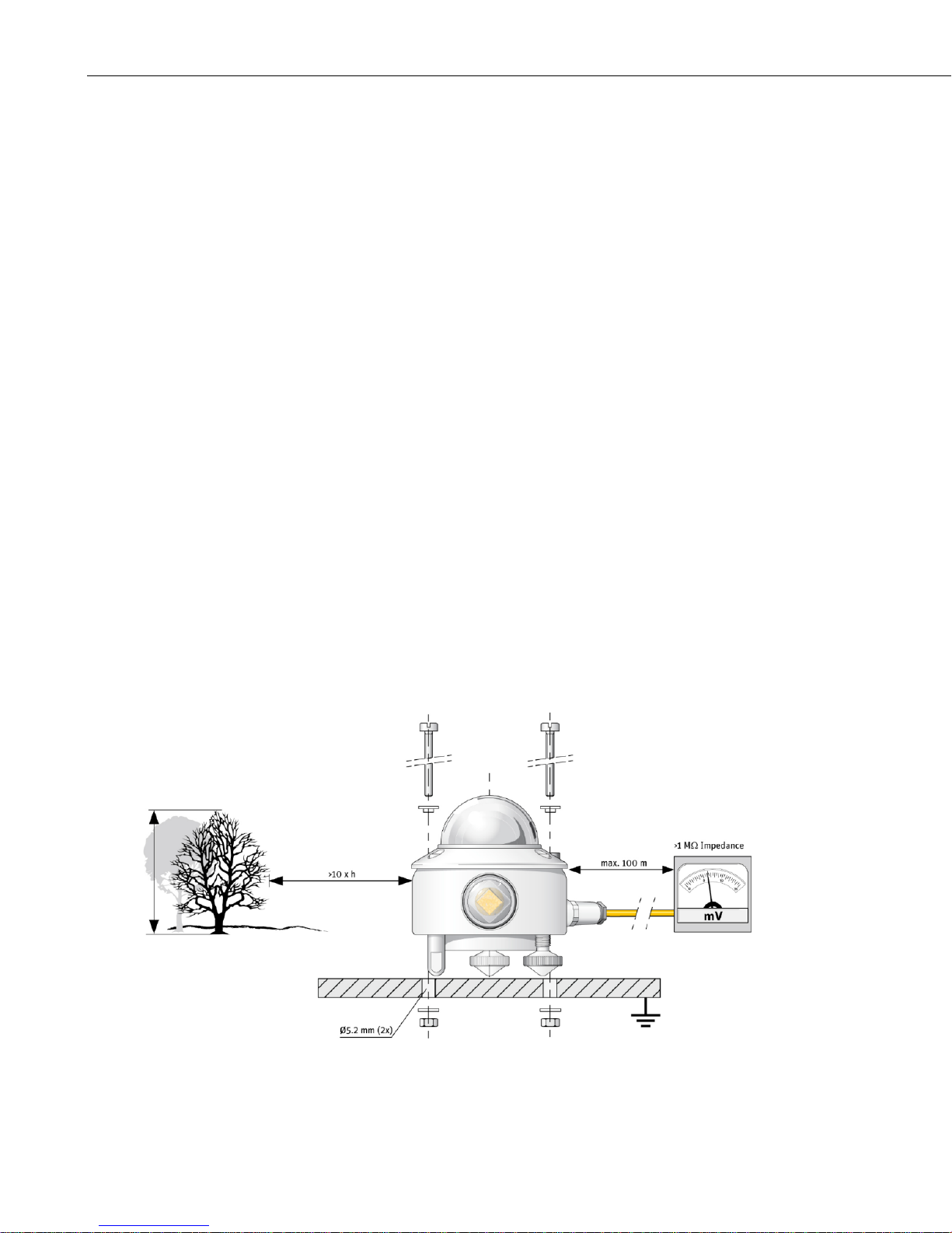
Site the CMP3 to allow easy access for maintenance while ideally avoiding any
obstructions or reflections above the plane of the sensing element. It is
important to mount the CMP3 such that a shadow or reflection will not be cast
on it at any time (FIGURE 7-1).
FIGURE 7-1. Pyranometer installation
6
Page 15

If this is not possible, try to choose a site where any obstruction over the
CAUTION
azimuth range between earliest sunrise and latest sunset has an elevation not
exceeding 5°. Diffuse solar radiation is less influenced by obstructions near the
horizon. For instance, an obstruction with an elevation of 5° over the whole
azimuth range of 360° decreases the downward diffuse solar radiation by only
0.8%.
The sensor should be mounted with the cable pointing towards the nearest
magnetic pole. For example, in the northern hemisphere, point the cable toward
the North Pole.
7.2 Mounting to an Instrument Mount
7.2.1 Required Tools
Tools required for installation on a tripod or tower:
Small and medium Phillips screwdrivers
5/16-inch, 1/2-inch open-end wrenches
5/32-inch Allen wrench
Tape measure
UV-resistant wire ties
Side-cut pliers
Compass
Step ladder
CMP3 Pyranometer
7.2.2 Mounting Procedure
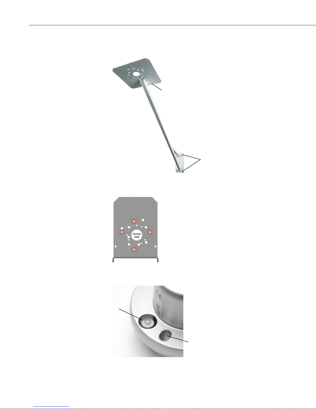
7.2.2.1 CM225 Solar Sensor Mounting Stand
The CM225 should never be mounted directly to a vertical
pipe. Instead the CM225 should be mounted to a crossarm.
This avoids reflections from the vertical pipe onto the
sensor.
1. Mount the crossarm to the tripod or tower.
7
Page 16

CMP3 Pyranometer
CM225 Stand
CM200-Series Crossarm
U-bolt Nuts
CM225 mounting
holes used for the
CMP3 are indicated
in orange.
Mounting Screw
Leveling Screw
Leveling Screw
Mounting
2. Place the CM225’s U-bolt in the bottom holes and secure the CM225 to
the crossarm by tightening the U-bolt nuts.
3. Loosely mount the pyranometer on the mounting stand. Do not fully
tighten the two mounting screws.
Screw
8
Page 17
CMP3 Pyranometer
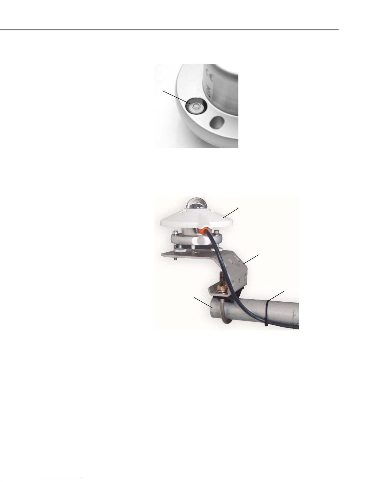
Bubble
Sun Shield
CM225 Mount
Cable Tie
Crossarm
4. Turn the levelling screws as required to bring the bubble of the bubble
level within the ring.
Level
5. Tighten the mounting screws to secure the assembly in its final position.
Check that the pyranometer is still correctly levelled and adjust as
necessary.
6. Attach the white plastic sun shield to the pyranometer.
7. Route the sensor cable along the underside of the crossarm to the
tripod/tower, and to the instrument enclosure.
8. Secure the cable to the crossarm and mast using cable ties.
9
Page 18
CMP3 Pyranometer
U-bolt Nuts
015ARM
015ARM mounting
holes used for the
CMP3 are indicated
in orange.
Hole for Mounting Screw
Bubble
Level
7.2.2.2 015ARM
1. Secure the 015ARM to the mast by tightening the U-bolt nuts.
2. Loosely mount the pyranometer on the mounting stand. Do not fully
tighten the two mounting screws.
3. Turn the leveling screws as required to bring the bubble of the bubble level
within the ring.
10
Page 19

4. Tighten the mounting screws to secure the assembly in its final position.
Red
Blue
Black
TABLE 7-1. Wire Color, Function, and Datalogger Connection for
NOTE
White
Black
Shield
Check that the pyranometer is still correctly leveled and adjust as
necessary.
5. Attach the white plastic sun shield to the pyranometer.
6. Route the sensor cable along the underside of the 015ARM’s arm to the
tripod/tower, and to the instrument enclosure.
7. Secure the cable to the crossarm and mast using cable ties.
7.3 Wiring to the Datalogger
A schematic diagram of the CMP3 is shown in FIGURE 7-2.
CMP3 Pyranometer
FIGURE 7-2. CMP3 Schematic
A CMP3 purchased from Campbell Scientific has different wiring
than a CMP3 purchased directly from Kipp & Zonen.
Connections to Campbell Scientific dataloggers for a differential measurement
are given in TABLE 7-1.
Differential Measurements
Wire Color Wire Function Datalogger Connection Terminal
1
,
White Signal High
U configured for differential input
DIFF H (differential high,
analog-voltage input)
U configured for differential input
Black Signal Reference
DIFF L (differential low,
analog-voltage input)
Clear Shield
1
U channels are automatically configured by the measurement instruction.
2
Jumper to AG or ⏚ with a user-supplied wire.
AG or ⏚ (analog ground)
1, 2
,
2
Although differential measurements are recommended because they have better
noise rejection, a single-ended measurement can be used if a differential
channel is not available (TABLE 7-2).
11
Page 20

CMP3 Pyranometer
TABLE 7-2. Wire Color, Function, and Datalogger Connection for
NOTE
Single-Ended Measurements
Wire Color Wire Function Datalogger Connection Terminal
1
U channels are automatically configured by the measurement instruction.
7.4 Programming
Short Cut is the best source for up-to-date datalogger programming code.
Programming code is needed when:
If your data acquisition requirements are simple, you can probably create and
maintain a datalogger program exclusively with Short Cut. If your data
acquisition needs are more complex, the files that Short Cut creates are a great
source for programming code to start a new program or add to an existing
custom program.
Short Cut cannot edit programs after they are imported and edited
in CRBasic Editor.
U configured for single-ended
White Signal
analog input
SE (single-ended, analog-voltage input)
Black Signal Reference
Clear Shield
AG or ⏚ (analog ground)
AG or ⏚ (analog ground)
• Creating a program for a new datalogger installation.
• Adding sensors to an existing datalogger program.
1
,
A Short Cut tutorial is available in Section 4, QuickStart (p. 2). If you wish to
import Short Cut code into CRBasic Editor to create or add to a customized
program, follow the procedure in Appendix A, Importing Short Cut Code Into
CRBasic Editor
(p. A-1). Programming basics for CRBasic dataloggers are
provided below. A complete program example can be found in Appendix B,
Example Program
Solar radiation can be reported as an average flux density (W m
flux density (MJ m
Appendix B, Example Program
(p. B-1).
–2
–2
). The appropriate multipliers are listed in TABLE 7-3.
(p. B-1), shows a CR1000 program that reports
) or daily total
both average and daily total solar radiation.
The CMP3 outputs a low level voltage ranging from 0 to a maximum of up to
20 mV, in natural light, depending on the calibration factor and radiation level.
A differential voltage measurement is recommended because it has better noise
rejection than a single-ended measurement. If a differential channel is not
available, a single-ended measurement can be used. The acceptability of a
single-ended measurement can be determined by simply comparing the results
of single-ended and differential measurements made under the same
conditions.
Nearby ac power lines, electric pumps, or motors can be a source of electrical
noise. If the sensor or datalogger is located in an electrically noisy
12
Page 21

7.4.1 Input Range
TABLE 7-3. Multipliers Required for Flux Density and Total Fluxes
W m–2
m
Average
MJ m–2
m • t • 0.000001
Total
cal cm–2 min–1
m • 1.434 • 0.001
Average
m = calibration factor in Wm–2/mV
CMP3 Pyranometer
environment, the measurement should be made with the 60 or 50 Hz rejection
integration option as shown in Appendix B, Example Program
(p. B-1).
The output voltage is usually between 5 and 20 mV per 1000 W•m–2. When
estimating the maximum likely value of sensor output a maximum value of
solar radiation of 1100 W•m
horizontal surface. Plane of array irradiances can exceed 1500 W•m
–2
can be used for field measurements on a
–2
.
Select the input range as follows:
7.4.2 Multiplier
1. Estimate the maximum expected input voltage by multiplying the
maximum expected irradiance (in W•m
–2
(µV / W•m
). Divide the answer by 1000 to give the maximum in
–2)
by the calibration factor
millivolt units.
2. Select the smallest input range which is greater than the maximum
expected input voltage. Normally the 50 mV range for the CR3000,
CR5000, or CR9000(X), and the 25 mV range for the CR800, CR850, and
CR1000, and the 200 mV range for the CR6. The exact range will depend
on the sensitivity of your individual sensor and the maximum expected
reading. With some dataloggers an autorange option can be used if
measurement time is not critical.
The slow or 60 Hz rejection integration gives a more noise-free reading. A fast
integration takes less power and allows for faster throughput.
The multiplier converts the millivolt reading to engineering units. The
calibration supplied by the manufacturer gives the output of the sensor (c) as
microvolts (V x 10
instructions give a default output in mV, the following equation should be used
to calculate the multiplier (m) to give the readings in Wm
–6
) per Wm–2. As the datalogger voltage measurement
–2
:
m = 1000/c
Other units can be used by adjusting the multiplier as shown in TABLE 7-3.
Units Multipliers Output Processing
kJ m–2
cal cm–2 m • t • 0.0239 • 0.001 Total
m • t • 0.001
Total
t = datalogger program execution interval in seconds
13
Page 22

CMP3 Pyranometer
NOTE
7.4.3 Offset
The offset will normally be fixed at zero as the sensor should output no
significant signal in dark conditions. In practice, because of the nature of
thermopile detector sensors, there will be some offset in dark conditions;
sometimes this offset can give negative light readings. This offset varies with
several factors, such as rate of change of sensor temperature, so it cannot be
removed with a fixed offset. Some users may wish to remove small negative
readings by including code after the measurement instructions that sets
negative readings to zero.
7.4.4 Output Format Considerations
When using the Campbell Scientific floating point data format to store data, the
largest number the datalogger can store in final storage is 6999 in low
resolution mode (FP2) and 99999 in high resolution mode (if available). If the
measurement value is totalized, there is some danger of over-ranging the output
limits. To avoid this issue, store the data in the in IEEE4 format, which can
represent a wider range of numbers.
8. Maintenance and Troubleshooting
All factory repairs and recalibrations require a returned material
authorization (RMA) and completion of the “Declaration of
Hazardous Material and Decontamination” form. Refer to the
Assistance page at the beginning of this manual for more
information.
8.1 Maintenance/Recalibrations
Inspect and clean the outer dome every week or so. Clean any accumulated
dust or debris off the dome and pyranometer body using a soft cloth dampened
with water or alcohol. Check that there is no condensation within the dome.
Check the data returned from the sensor as it will show the first indication of a
fault. When doing this you should be aware of several expected phenomena
that can cause strange measurements. In particular on clear, windless nights the
outer dome temperature of horizontally placed pyranometers can fall as low as
the dew point temperature of the air, due to infrared radiation exchange with
the cold sky. (The effective sky temperature can be 30 °C lower than the
ground temperature, which results in an infrared emission of –150 Wm
this happens, dew, glazed frost or hoar frost can be precipitated on the top of
the outer dome and can stay there for several hours in the morning. An ice cap
on the dome is a strong diffuser and can increase the pyranometer signal by up
to 50% in the first hours after sunrise.
The calibration of the CMP3 may drift with time and exposure to radiation.
Campbell Scientific recommends recalibrating every two years. The sensor
should be returned to Campbell Scientific, the manufacturer, or a calibration
lab with facilities to calibrate radiation sensors.
–2
). If
14
Page 23

8.2 Troubleshooting
Symptom: –9999 or radiation values around 0
1. Check that the sensor is wired to the differential channel specified by the
measurement instruction.
2. Verify that the range is correct for the datalogger type.
3. Measure the impedance across the red and blue sensor wires. This should
be around 100 ohms plus the cable resistance (typically 0.1 ohm/m). If the
resistance is very low there may be a short circuit (check the wiring).
Resistances somewhat lower than expected could be due to water ingress
into the sensor or enclosure connectors. If the resistance is infinite, there
is a broken connection (check the wiring).
4. Disconnect the sensor cable and check the voltage output from the sensor.
With the sensor located 8 inches below a 60 W incandescent light bulb,
the voltage should be approximately 2.5 mV. No voltage indicates a
problem with the sensor.
Symptom: sensor signal is unrealistically high or low
CMP3 Pyranometer
1. Check that the right calibration factor has been properly entered into the
datalogger program. Please note that each sensor has its own individual
calibration factor.
2. Check the condition of the sensor cable.
Symptom: sensor signal shows unexpected variations
1. Check for the presence of strong sources of electromagnetic radiation
(radar, radio).
2. Check the condition and the connection of the sensor shield wire.
3. Check the condition of the sensor cable.
15
Page 24

CMP3 Pyranometer
16
Page 25

NOTE
Appendix A. Importing Short Cut Code
Into CRBasic Editor
This tutorial shows:
• How to import a Short Cut program into a program editor for
additional refinement
• How to import a wiring diagram from Short Cut into the comments of
a custom program
Short Cut creates files, which can be imported into CRBasic Editor. Assuming
defaults were used when Short Cut was installed, these files reside in the
C:\campbellsci\SCWin folder:
• .DEF (wiring and memory usage information)
• .CR6 (CR6 datalogger code)
• .CR1 (CR1000 datalogger code)
• .CR8 (CR800 datalogger code)
• .CR3 (CR3000 datalogger code)
• .CR5 (CR5000 datalogger code)
• .CR9 (CR9000(X) datalogger code)
Use the following procedure to import Short Cut code and wiring diagram into
CRBasic Editor.
1. Create the Short Cut program following the procedure in Section 4,
QuickStart
file name used when saving the Short Cut program.
2. Open CRBasic Editor.
3. Click File | Open. Assuming the default paths were used when Short Cut
was installed, navigate to C:\CampbellSci\SCWin folder. The file of
interest has the .CR6, .CR1, .CR8, .CR3, .CR5, or .CR9 extension. Select
the file and click Open.
4. Immediately save the file in a folder different from
C:\Campbellsci\SCWin, or save the file with a different file name.
Once the file is edited with CRBasic Editor, Short Cut can no
longer be used to edit the datalogger program. Change the name
of the program file or move it, or Short Cut may overwrite it next
time it is used.
5. The program can now be edited, saved, and sent to the datalogger.
6. Import wiring information to the program by opening the associated .DEF
file. Copy and paste the section beginning with heading “-Wiring for
CRXXX–” into the CRBasic program, usually at the head of the file. After
pasting, edit the information such that an apostrophe (') begins each line.
This character instructs the datalogger compiler to ignore the line when
compiling.
(p. 2). Finish the program and exit Short Cut. Make note of the
A-1
Page 26

Appendix A. Importing Short Cut Code Into CRBasic Editor
A-2
Page 27

TABLE B-1. Wiring for Example Program
⏚
CRBasic Example B-1. CR1000 Example Program
'CR1000
If Solar_Wm2<0 Then Solar_Wm2=0
Appendix B. Example Program
The following program measures the CMP3 every 10 s and converts the mV
output to Wm
for the example program. The program outputs an hourly average flux (Wm
and a daily total flux density (MJ m
–2
and MJm–2. A sensor calibration of 15.02 µV per Wm–2 is used
–2
).
Wiring for the example is given in TABLE B-1.
Color Description CR1000
White Signal (+) DIFF Analog High
Black Signal (–) DIFF Analog Low1
Shield Shield
1
Jumper to AG or ⏚ with user-supplied wire.
B.1 CR1000 Example Program
'Declare Variables and Units
Public Solar_Wm2
Public Solar_MJ
Units Solar_Wm2=W/m²
Units Solar_MJ=MJ/m²
'Hourly Data Table
DataTable(Table1,True,-1)
DataInterval(0,60,Min,10)
Average(1,Solar_Wm2,FP2,False)
EndTable
'Daily Data Table
DataTable(Table2,True,-1)
DataInterval(0,1440,Min,10)
Totalize(1,Solar_MJ,IEEE4,False)
EndTable
'Main Program
BeginProg
Scan(10,Sec,1,0)
'CMP3 Pyranometer measurement in Wm-2:
'The Multiplier (m) for this example is based upon a sensor calibration (c) of
'15.02 µV/Wm-2, and will be different for each sensor.
'Multiplier (m) = 1000/c = 66.577896.
VoltDiff(Solar_Wm2,1,mV25,1,True,0,_60Hz,66.577896,0) 'use the 50 mV range for the
'CR3000, CR5000 and CR9000
'Set negative readings to zero:
–2
),
B-1
Page 28

Appendix B. Example Program
EndProg
'Calculate units in MJ, where MJ = m * t * 0.000001. m = Solar_Wm2 from above, and
't = 10 (scan interval)
Solar_MJ=Solar_Wm2*0.00001
'Call Data Tables and Store Data
CallTable(Table1)
CallTable(Table2)
NextScan
B-2
Page 29

Page 30

Campbell Scientific Companies
Campbell Scientific, Inc.
815 West 1800 North
Logan, Utah 84321
UNITED STATES
www.campbellsci.com • info@campbellsci.com
Campbell Scientific Africa Pty. Ltd.
PO Box 2450
Somerset West 7129
SOUTH AFRICA
www.campbellsci.co.za • cleroux@csafrica.co.za
Campbell Scientific Southeast Asia Co., Ltd.
877/22 Nirvana@Work, Rama 9 Road
Suan Luang Subdistrict, Suan Luang District
Bangkok 10250
THAILAND
www.campbellsci.asia • info@campbellsci.asia
Campbell Scientific Australia Pty. Ltd.
PO Box 8108
Garbutt Post Shop QLD 4814
AUSTRALIA
www.campbellsci.com.au • info@campbellsci.com.au
Campbell Scientific (Beijing) Co., Ltd.
8B16, Floor 8 Tower B, Hanwei Plaza
7 Guanghua Road
Chaoyang, Beijing 100004
P.R. CHINA
www.campbellsci.com • info@campbellsci.com.cn
Campbell Scientific do Brasil Ltda.
Rua Apinagés, nbr. 2018 ─ Perdizes
CEP: 01258-00 ─ São Paulo ─ SP
BRASIL
www.campbellsci.com.br • vendas@campbellsci.com.br
Please visit www.campbellsci.com to obtain contact information for your local US or international representative.
Campbell Scientific Canada Corp.
14532 – 131 Avenue NW
Edmonton AB T5L 4X4
CANADA
www.campbellsci.ca • dataloggers@campbellsci.ca
Campbell Scientific Centro Caribe S.A.
300 N Cementerio, Edificio Breller
Santo Domingo, Heredia 40305
COSTA RICA
www.campbellsci.cc • info@campbellsci.cc
Campbell Scientific Ltd.
Campbell Park
80 Hathern Road
Shepshed, Loughborough LE12 9GX
UNITED KINGDOM
www.campbellsci.co.uk • sales@campbellsci.co.uk
Campbell Scientific Ltd.
3 Avenue de la Division Leclerc
92160 ANTONY
FRANCE
www.campbellsci.fr • info@campbellsci.fr
Campbell Scientific Ltd.
Fahrenheitstraße 13
28359 Bremen
GERMANY
www.campbellsci.de • info@campbellsci.de
Campbell Scientific Spain, S. L.
Avda. Pompeu Fabra 7-9, local 1
08024 Barcelona
SPAIN
www.campbellsci.es • info@campbellsci.es
 Loading...