

Page 1
INSTRUCTION MANUAL
CMP6, CMP11, and
Copyright © 2006- 2015
Campbell Scientific, Inc.
CMP21 Pyranometers
Revision: 4/15
Page 2

Page 3

Limited Warranty
“Products manufactured by CSI are warranted by CSI to be free from defects in
materials and workmanship under normal use and service for twelve months
from the date of shipment unless otherwise specified in the corresponding
product manual. (Product manuals are available for review online at
www.campbellsci.com.) Products not manufactured by CSI, but that are resold
by CSI, are warranted only to the limits extended by the original manufacturer.
Batteries, fine-wire thermocouples, desiccant, and other consumables have no
warranty. CSI’s obligation under this warranty is limited to repairing or
replacing (at CSI’s option) defective Products, which shall be the sole and
exclusive remedy under this warranty. The Customer assumes all costs of
removing, reinstalling, and shipping defective Products to CSI. CSI will return
such Products by surface carrier prepaid within the continental United States of
America. To all other locations, CSI will return such Products best way CIP
(port of entry) per Incoterms ® 2010. This warranty shall not apply to any
Products which have been subjected to modification, misuse, neglect, improper
service, accidents of nature, or shipping damage. This warranty is in lieu of all
other warranties, expressed or implied. The warranty for installation services
performed by CSI such as programming to customer specifications, electrical
connections to Products manufactured by CSI, and Product specific training, is
part of CSI's product warranty. CSI EXPRESSLY DISCLAIMS AND
EXCLUDES ANY IMPLIED WARRANTIES OF MERCHANTABILITY
OR FITNESS FOR A PARTICULAR PURPOSE. CSI hereby disclaims,
to the fullest extent allowed by applicable law, any and all warranties and
conditions with respect to the Products, whether express, implied or
statutory, other than those expressly provided herein.”
Page 4

Assistance
Products may not be returned without prior authorization. The following
contact information is for US and international customers residing in countries
served by Campbell Scientific, Inc. directly. Affiliate companies handle
repairs for customers within their territories. Please visit
www.campbellsci.com to determine which Campbell Scientific company serves
your country.
To obtain a Returned Materials Authorization (RMA), contact CAMPBELL
SCIENTIFIC, INC., phone (435) 227-9000. After an application engineer
determines the nature of the problem, an RMA number will be issued. Please
write this number clearly on the outside of the shipping container. Campbell
Scientific’s shipping address is:
CAMPBELL SCIENTIFIC, INC.
RMA#_____
815 West 1800 North
Logan, Utah 84321-1784
For all returns, the customer must fill out a “Statement of Product Cleanliness
and Decontamination” form and comply with the requirements specified in it.
The form is available from our web site at www.campbellsci.com/repair. A
completed form must be either emailed to repair@campbellsci.com or faxed to
(435) 227-9106. Campbell Scientific is unable to process any returns until we
receive this form. If the form is not received within three days of product
receipt or is incomplete, the product will be returned to the customer at the
customer’s expense. Campbell Scientific reserves the right to refuse service on
products that were exposed to contaminants that may cause health or safety
concerns for our employees.
Page 5

Precautions
DANGER — MANY HAZARDS ARE ASSOCIATED WITH INSTALLING, USING, MAINTAINING, AND WORKING ON OR AROUND
TRIPODS, TOWERS, AND ANY ATTACHMENTS TO TRIPODS AND TOWERS SUCH AS SENSORS, CROSSARMS, ENCLOSURES,
ANTENNAS, ETC. FAILURE TO PROPERLY AND COMPLETELY ASSEMBLE, INSTALL, OPERATE, USE, AND MAINTAIN TRIPODS,
TOWERS, AND ATTACHMENTS, AND FAILURE TO HEED WARNINGS, INCREASES THE RISK OF DEATH, ACCIDENT, SERIOUS
INJURY, PROPERTY DAMAGE, AND PRODUCT FAILURE. TAKE ALL REASONABLE PRECAUTIONS TO AVOID THESE HAZARDS.
CHECK WITH YOUR ORGANIZATION'S SAFETY COORDINATOR (OR POLICY) FOR PROCEDURES AND REQUIRED PROTECTIVE
EQUIPMENT PRIOR TO PERFORMING ANY WORK.
Use tripods, towers, and attachments to tripods and towers only for purposes for which they are designed. Do not exceed design
limits. Be familiar and comply with all instructions provided in product manuals. Manuals are available at www.campbellsci.com or
by telephoning (435) 227-9000 (USA). You are responsible for conformance with governing codes and regulations, including safety
regulations, and the integrity and location of structures or land to which towers, tripods, and any attachments are attached. Installation
sites should be evaluated and approved by a qualified engineer. If questions or concerns arise regarding installation, use, or
maintenance of tripods, towers, attachments, or electrical connections, consult with a licensed and qualified engineer or electrician.
General
• Prior to performing site or installation work, obtain required approvals and permits. Comply
with all governing structure-height regulations, such as those of the FAA in the USA.
• Use only qualified personnel for installation, use, and maintenance of tripods and towers, and
any attachments to tripods and towers. The use of licensed and qualified contractors is
highly recommended.
• Read all applicable instructions carefully and understand procedures thoroughly before
beginning work.
• Wear a hardhat and eye protection, and take other appropriate safety precautions while
working on or around tripods and towers.
• Do not climb tripods or towers at any time, and prohibit climbing by other persons. Take
reasonable precautions to secure tripod and tower sites from trespassers.
• Use only manufacturer recommended parts, materials, and tools.
Utility and Electrical
• You can be killed or sustain serious bodily injury if the tripod, tower, or attachments you are
installing, constructing, using, or maintaining, or a tool, stake, or anchor, come in contact
with overhead or underground utility lines.
• Maintain a distance of at least one-and-one-half times structure height, 20 feet, or the
distance required by applicable law, whichever is greater, between overhead utility lines and
the structure (tripod, tower, attachments, or tools).
• Prior to performing site or installation work, inform all utility companies and have all
underground utilities marked.
• Comply with all electrical codes. Electrical equipment and related grounding devices should
be installed by a licensed and qualified electrician.
Elevated Work and Weather
• Exercise extreme caution when performing elevated work.
• Use appropriate equipment and safety practices.
• During installation and maintenance, keep tower and tripod sites clear of un-trained or non-
essential personnel. Take precautions to prevent elevated tools and objects from dropping.
• Do not perform any work in inclement weather, including wind, rain, snow, lightning, etc.
Maintenance
• Periodically (at least yearly) check for wear and damage, including corrosion, stress cracks,
frayed cables, loose cable clamps, cable tightness, etc. and take necessary corrective actions.
• Periodically (at least yearly) check electrical ground connections.
WHILE EVERY ATTEMPT IS MADE TO EMBODY THE HIGHEST DEGREE OF SAFETY IN ALL CAMPBELL SCIENTIFIC PRODUCTS,
THE CUSTOMER ASSUMES ALL RISK FROM ANY INJURY RESULTING FROM IMPROPER INSTALLATION, USE, OR
MAINTENANCE OF TRIPODS, TOWERS, OR ATTACHMENTS TO TRIPODS AND TOWERS SUCH AS SENSORS, CROSSARMS,
ENCLOSURES, ANTENNAS, ETC.
Page 6

Page 7

Table of Contents
PDF viewers: These page numbers refer to the printed version of this document. Use the
PDF reader bookmarks tab for links to specific sections.
1. Introduction ................................................................. 1
2. Cautionary Statements ............................................... 1
3. Initial Inspection ......................................................... 1
3.1 Ships With ............................................................................................ 1
3.2 Calibration Certificate .......................................................................... 2
4. Quickstart .................................................................... 2
4.1 Siting .................................................................................................... 2
4.2 Mounting .............................................................................................. 2
4.3 Short Cut Programming ....................................................................... 5
5. Overview ...................................................................... 7
5.1 Models ................................................................................................. 7
5.2 Construction ......................................................................................... 8
6. Specifications ............................................................. 8
6.1 Pyranometers ........................................................................................ 8
6.2 CVF4 Ventilation Unit ......................................................................... 9
7. Installation ................................................................. 10
7.1 Mounting to a Tripod or Tower ......................................................... 10
7.2 Wiring ................................................................................................ 11
7.2.1 CMP6, CMP11, and CMP21 Thermopile Schematic ................. 12
7.2.2 CMP6 and CMP11 Wiring .......................................................... 12
7.2.3 CMP21 Wiring ............................................................................ 13
7.3 Programming ...................................................................................... 14
7.3.1 Solar Radiation Measurements ................................................... 14
7.3.1.1 Input Range ...................................................................... 15
7.3.1.2 Multiplier .......................................................................... 15
7.3.1.3 Offset ................................................................................ 16
7.3.1.4 Output Format Considerations ......................................... 16
7.3.2 CMP21 Internal Thermistor Measurement ................................. 16
8. Maintenance/Troubleshooting ................................. 17
8.1 Maintenance ....................................................................................... 17
8.1.1 Cleaning Domes .......................................................................... 17
8.1.2 Changing the Desiccant .............................................................. 17
8.1.3 Check Sensor Output .................................................................. 18
8.2 Recalibration ...................................................................................... 19
8.3 Troubleshooting ................................................................................. 19
i
Page 8

Table of Contents
Appendices
Importing Short Cut Code Into CRBasic Editor ... A-1
A.
A.1 Importing Short Cut Code into a Program Editor ............................ A-1
B. Example Programs .................................................. B-1
B.1 CR1000 Example Program for Measuring a CMP6 ........................ B-1
B.2 CR1000 Example Program for Measuring a CMP11 ...................... B-2
B.3 CR1000 Example Program for Measuring a CMP21 ...................... B-3
C. CVF4 Ventilation Unit .............................................. C-1
C.1 General Information ........................................................................ C-1
C.2 CVF4 Components .......................................................................... C-1
C.3 CVF4 Installation ............................................................................ C-3
C.4 Wiring ............................................................................................. C-7
C.4.1 Implementation Example ......................................................... C-7
C.5 CVF4 Example Program ................................................................. C-8
C.6 CVF4 Heater/Ventilator Maintenance ............................................. C-9
Figures
Tables
4-1. Pyranometer installation ...................................................................... 3
4-2. Pyranometer mounted horizontally for the Northern Hemisphere
(left) and Southern Hemisphere (right) ............................................ 3
4-3. Two views of a pyranometer mounted at an angle for the
Northern Hemisphere ....................................................................... 4
4-4. Pyranometer mounted at an angle for the Southern Hemisphere ........ 4
6-1. Dimensions of the CMP6, CMP11, and CMP21 ................................. 8
7-1. Exploded view of the pyranometer .................................................... 11
7-2. CMP6, CMP11, and CMP21 thermopile detector schematic ............ 12
8-1. Reading is reduced if dome is not dry or clean ................................. 17
8-2. Changing the desiccant ...................................................................... 18
C-1. CVF4 Components (top view, no cover) ......................................... C-2
C-2. CVF4 Components (bottom view) .................................................. C-2
C-3. CVF4 Ventilation Unit and Ships With Kit ..................................... C-3
C-4. Crossarm and 17593 NU-RAIL Mounted to Mast (exploded
view) ............................................................................................ C-4
C-5. CM220 Right-Angle Mounting Bracket attached to CM200-
series crossarm ............................................................................. C-4
C-6. Mounting CVF4 feet to a mounting stand ....................................... C-5
C-7. Mounting the pyranometer to the CVF4 .......................................... C-5
C-8. CVF4 Mounted to 31153 Stand (pyranometer not shown) ............. C-6
C-9. CVF4 filter replacement, pn 31435 ............................................... C-10
6-1. CMP-series Specifications .................................................................. 9
7-1. CMP6 and CMP11 Differential Connections to Campbell
Scientific Dataloggers .................................................................... 12
7-2. CMP6 and CMP11 Single-Ended Connections to Campbell
Scientific Dataloggers .................................................................... 13
7-3. CMP21 Differential Connections to Campbell Scientific
Dataloggers .................................................................................... 13
ii
Page 9

Table of Contents
7-4. CMP21 Single-Ended Connections to Campbell Scientific
Dataloggers ..................................................................................... 14
7-5. Multipliers Required for Flux Density and Total Fluxes ................... 16
B-1. CR1000 Wiring for CMP6 Example Program ................................. B-1
B-2. CR1000 Wiring for CMP11 Example Program ............................... B-2
B-3. CR1000 Wiring for CMP21 Example Program ............................... B-3
C-1. CVF4 Wiring ................................................................................... C-7
iii
Page 10

Table of Contents
iv
Page 11

NOTE
CMP6, CMP11, and CMP21
Pyranometers
1. Introduction
CMP-series pyranometers are designed for continuous outdoor monitoring of
solar radiation intensity. A flat spectral sensitivity from 285 to 2800 nm
enables accurate measurements in natural sunlight, under plant canopies, and in
green houses or buildings. When inverted, these pyranometers can measure
reflected solar radiation. Uses include monitoring global horizontal irradiance
(GHI) and plane of array irradiance (POA). Diffuse sky radiation can also be
measured with the use of a shade mechanism.
This manual provides information only for CRBasic dataloggers.
It is also compatible with many of our retired Edlog dataloggers.
For Edlog datalogger support, see an older manual at
www.campbellsci.com\old-manuals or contact a Campbell
Scientific application engineer for assistance.
2. Cautionary Statements
• READ AND UNDERSTAND the Precautions section at the front of this
manual.
• CMP-series pyranometers are rugged, but they should be handled as
precision scientific instruments.
• Care should be taken when opening the shipping package to not damage or
cut the cable jacket. If damage to the cable is suspected, consult with a
Campbell Scientific applications engineer.
3. Initial Inspection
Check the contents of the shipment. If there is a shortage (see Section 3.1,
Ships With
during transport, immediately file a claim with the carrier and contact
Campbell Scientific to facilitate repair or replacement.
The model number and cable length are printed on a label at the connection end
of the cable. Check this information against the shipping documents to ensure
the correct product and cable length are received.
3.1 Ships With
(p. 1)), contact Campbell Scientific. If any damage has occurred
(2) Bolts for mounting from original manufacturer
(1) Instruction Manual from original manufacturer
(1) Sun Shield from original manufacturer
(2) Nylon washers from original manufacturer
1
Page 12

CMP6, CMP11, and CMP21 Pyranometers
NOTE
NOTE
3.2 Calibration Certificate
Each pyranometer is shipped with an instruction manual provided by Kipp &
Zonen that contains information concerning its construction, spectral
sensitivity, cosine response, and a simple sensor check out procedure. Included
with the sensor and manual is a calibration certificate with the sensor
sensitivity value and serial number.
Cross check this serial number against the serial number on your
pyranometer to ensure that the given sensitivity value corresponds
to your sensor.
4. Quickstart
4.1 Siting
The pyranometer is usually installed horizontally for global horizontal
measurements. However, the pyranometer can be installed at any angle for
POA measurements and in the inverted position for reflected measurements. In
all cases it will measure the solar flux incident on the sensor surface.
4.2 Mounting
Site the pyranometer to allow easy access for maintenance while ideally
avoiding any obstructions or reflections above the plane of the sensing element.
It is important to mount the pyranometer such that a shadow or reflection will
not be cast on it at any time.
If this is not possible, try to choose a site where any obstruction over the
azimuth range between earliest sunrise and latest sunset has an elevation not
exceeding 5°. Diffuse solar radiation is less influenced by obstructions near
the horizon. For instance, an obstruction with an elevation of 5° over the
whole azimuth range of 360° decreases the downward diffuse solar radiation
by only 0.8%.
The sensor should be mounted with the cable pointing towards the nearest
magnetic pole (e.g., in the Northern Hemisphere point the cable toward the
North Pole); see FIGURE 4-1 through FIGURE 4-4.
Appendix C, CVF4 Ventilation Unit
information for the CVF4 ventilation unit.
See Section 7.1, Mounting to a Tripod or Tower (p. 10), for more information.
(p. C-1), provides the mounting
2
Page 13

CMP6, CMP11, and CMP21 Pyranometers
CM2XX-Series
Crossarm
FIGURE 4-1. Pyranometer installation
FIGURE 4-2. Pyranometer mounted horizontally for the Northern
Hemisphere (left) and Southern Hemisphere (right)
3
Page 14

CMP6, CMP11, and CMP21 Pyranometers
FIGURE 4-3. Two views of a pyranometer mounted at an angle for the
Northern Hemisphere
4
FIGURE 4-4. Pyranometer mounted at an angle for the Southern
Hemisphere
Page 15
4.3 Short Cut Programming
NOTE
The CMP21 is not included in Short Cut. Refer to Section 7,
Installation (p. 10), for wiring and programming information if not
using Short Cut.
Short Cut is an easy way to program your datalogger to measure the
pyranometer and assign datalogger wiring terminals. Use the following
procedure to get started.
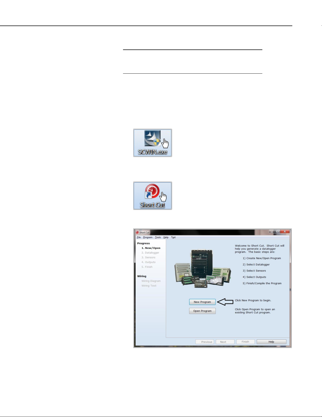
1. Install Short Cut by clicking on the install file icon. Get the install file
from either www.campbellsci.com, the ResourceDVD, or find it in
installations of LoggerNet, PC200W, PC400, or RTDAQ software.
2. The Short Cut installation should place a Short Cut icon on the desktop of
your computer. To open Short Cut, click on this icon.
CMP6, CMP11, and CMP21 Pyranometers
3. When Short Cut opens, select New Program.
5
Page 16
CMP6, CMP11, and CMP21 Pyranometers
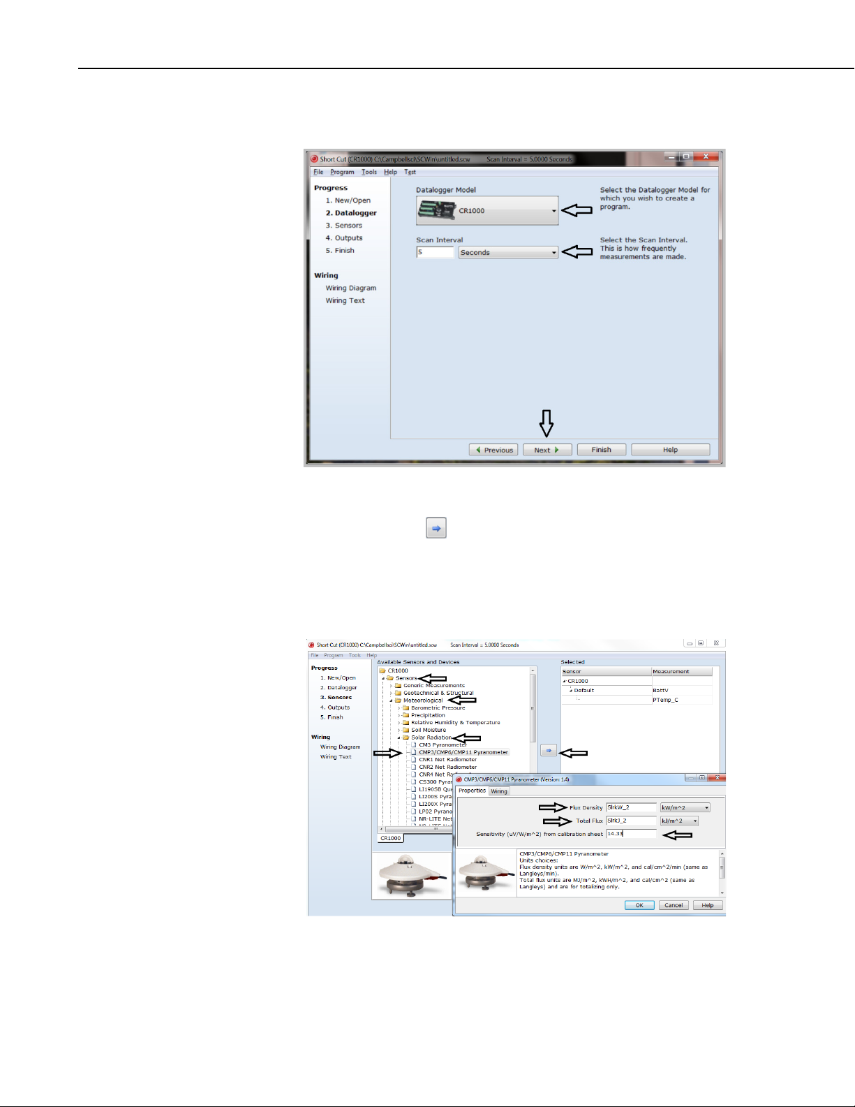
4. Select Datalogger Model and Scan Interval (default of 5 seconds is OK
for most applications). Click Next.
5. Under the Available Sensors and Devices list, select Sensors |
Meteorological | Solar Radiation folder. Select CMP3/CMP6/CMP11
Pyranometer. Click to move the selection to the Selected device
window. Default units are kW/m
total flux. These can be changed by clicking the Flux Density and Total
Flux boxes and selecting different values. A sensitivity value needs to be
entered. This value is unique to each sensor and is listed on the calibration
sheet that is included with the sensor.
2
for flux density units and kJ/ m2 for
6
Page 17
CMP6, CMP11, and CMP21 Pyranometers
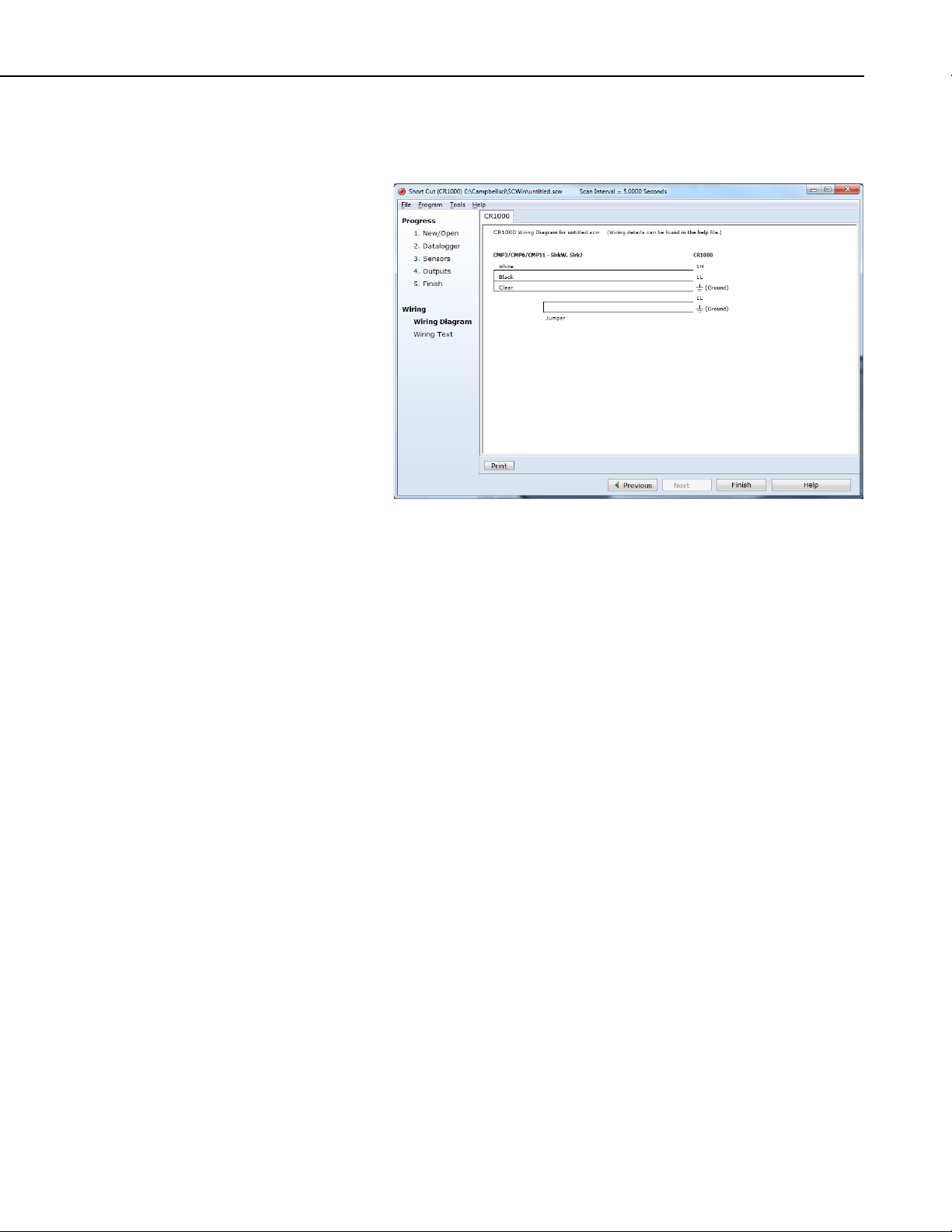
6. After selecting the sensor, click at the left of the screen on Wiring
Diagram to see how the sensor is to be wired to the datalogger. The
wiring diagram can be printed out now or after more sensors are added.
5. Overview
5.1 Models
7. Select any other sensors you have, then finish the remaining Short Cut
steps to complete the program. The remaining steps are outlined in Short
Cut Help, which is accessed by clicking on Help | Contents |
Programming Steps.
8. If LoggerNet, PC400, RTDAQ, or PC200W is running on your PC, and the
PC to datalogger connection is active, you can click Finish in Short Cut
and you will be prompted to send the program just created to the
datalogger.
9. If the sensor is connected to the datalogger, as shown in the wiring
diagram in step 6, check the output of the sensor in the datalogger support
software data display to make sure it is making reasonable measurements.
CMP-series models differ in accuracy and performance (see Section 6,
Specifications
individually optimized compensation of the measurements.
The –L portion of the model number indicates that the pyranometer has a userspecified cable length. The pyranometers have several cable termination
options. Their cables can terminate in:
(p. 8)). The CMP21 also includes an internal thermistor allowing
• Pigtails that connect directly to a Campbell Scientific datalogger
(cable termination option –PT).
• Connector that attaches to a prewired enclosure (cable termination
option –PW).
• Connector that attaches to a CWS900 Wireless Sensor Interface (cable
termination option –CWS). The CWS900 enables the pyranometer to
7
Page 18
CMP6, CMP11, and CMP21 Pyranometers
be used in a wireless sensor network. Please note that this option is
not available for the CMP21.
5.2 Construction
The pyranometers consist of a thermopile sensor, housing, two glass domes,
and cable. The thermopile is coated with a black absorbent coating. The paint
absorbs the radiation and converts it to heat. The resultant temperature
difference is converted to a voltage by the copper-constantan thermopile. The
thermopile is encapsulated in the housing in such a way that it has a field of
view of 180 degrees and the angular characteristics needed to fulfill the cosine
response requirements.
6. Specifications
Features:
• Double glass dome
• Integrated bubble level is visible without removing sun shield
• Measures reflected solar radiation when inverted
• Desiccant-filled drying cartridge prevents dew from forming on the
inner sides of the domes
• Provides measurements in direct sunlight, under plant canopies, when
the sky is cloudy, and in artificial light
• Compatible with Campbell Scientific CRBasic dataloggers: CR6,
CR200(X) series, CR800 series, CR1000, CR3000, CR5000, and
CR9000(X).
6.1 Pyranometers
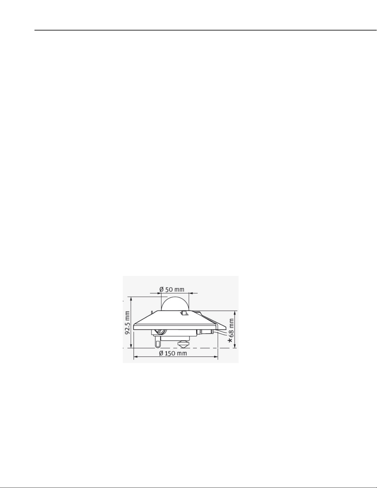
Dimensions are shown in FIGURE 6-1 and the other specifications are
provided in TABLE 6-1.
FIGURE 6-1. Dimensions of the CMP6, CMP11, and CMP21
8
Page 19
CMP6, CMP11, and CMP21 Pyranometers
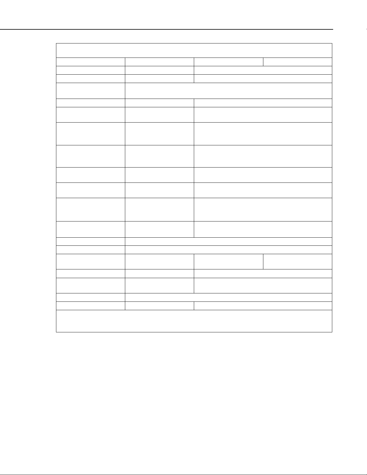
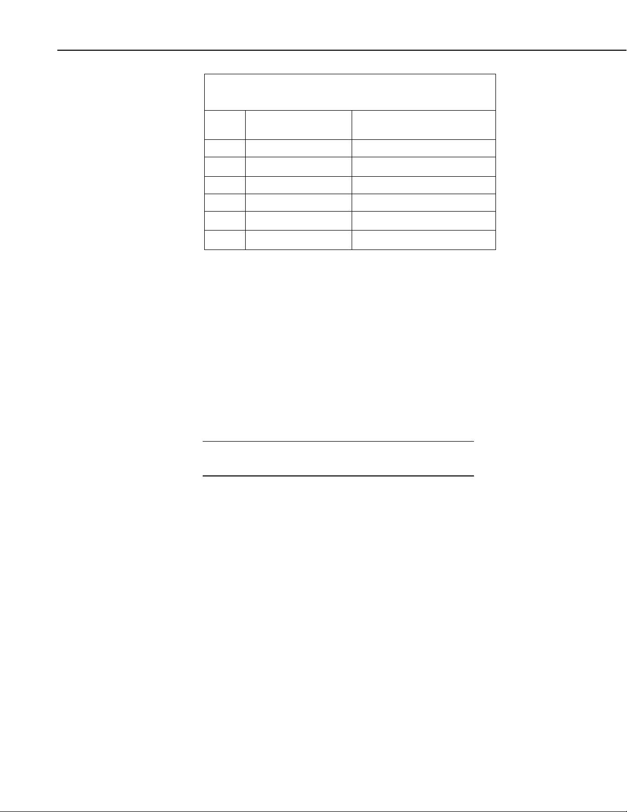
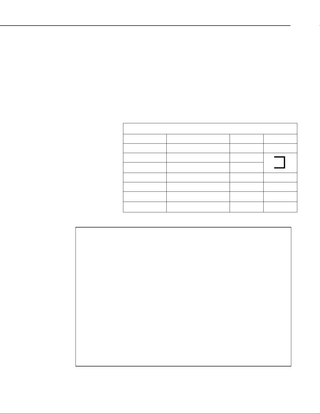
TABLE 6-1. CMP-series Specifications
Specification
CMP6
CMP11
CMP21
ISO Classification
First Class
Secondary Standard
Maximum irradiance
2000 W•m–2
4000 W•m–2
Spectral range
(50% points)
Response time (95 %)
<18 s
<5 s
Expected daily
Zero offset due to
Zero offset due to
•
Non-stability
(change/year)
Non-linearity
Directional error
Tilt error
(at 1000 W•m–2)
Level accuracy
0.1°
Operating temperature
–40 to 80 °C
Temperature dependence
Sensitivity
5 to 20 µV / W•m–2
7 to 14 µV / W•m–2
Typical signal output for
atmospheric applications
Weight
0.6 kg (1.3 lb) without cable; 0.9 kg (2 lb) with 10 m (33 ft) cable
Impedance*
20 to 200 Ω
10 to 100 Ω
* Impedance is defined as the total electrical impedance at the radiometer output connector fitted to the housing.
radiometer.
285 to 2800 nm
uncertainty
thermal radiation
(200 W•m–2)
temperature change
hr–1)
(5 K
(0 to 1000 W•m–2)
(up to 80° with 1000
–2
W•m
of sensitivity
beam)
<5% <2%
<15 W•m–2 <7 W•m–2
<4 W•m–2 <2 W•m–2
<1 % <0.5%
<1% <0.2%
<20 W•m–2 <10 W•m–2
<1% <0.2%
<4% (–10 to 40 °C) <1% (–10 to 40 °C) <1% (–20 to 50 °C)
0 to 20 mV 0 to 15 mV
It arises from the electrical resistance in the thermal junctions, wires, and passive electronics within the
6.2 CVF4 Ventilation Unit
Compatible pyranometers: CMP6, CMP11, CMP21
Power supply: 12 Vdc, 0.9 A (with 5.5 W Heater)
Operating temperature range: –40 to 70 °C
Ventilation power: 5 W continuously
Heating power: 5.5 W
9
Page 20

CMP6, CMP11, and CMP21 Pyranometers
NOTE
Heater induced offset: <1 W•m–2 (with CMP11 Pyranometer)
Weight without cable: 1.6 kg (3.5 lb)
Height: 12.95 cm (5.1 in)
Length: 35.5 cm (14.0 in)
Width: 23.0 cm (9.1 in)
7. Installation
If you are programming your datalogger with Short Cut, skip Section 7.2,
Wiring
for you. See Section 4.3, Short Cut Programming
7.1 Mounting to a Tripod or Tower
Tools required for installation on a tripod or tower:
Small and medium Phillips screwdrivers
5/16 inch, 1/2 inch open end wrenches
5/32 inch Allen wrench
Tape measure
UV-resistant wire ties
Side-cut pliers
Compass
Step ladder
(p. 11), and Section 7.3, Programming (p. 14). Short Cut does this work
(p. 5), for a tutorial.
The pyranometers include a bubble level and two leveling screws, which allow
them to be leveled horizontally without using a leveling base. They typically
mount to a crossarm via the CM255 or CM255LS Mounting Stand.
The CM255 and CM255LS are not compatible with a pyranometer
housed in a CVF4 Ventilation Unit. The CVF4 mounts to a tripod
or tower using the 31153 mounting stand and either the CM220
Right-Angle Mount or the 17953 1 inch by 1 inch NU-RAIL.
Refer to
information.
The CM255 and CM255LS can be adjusted to any angle from horizontal to
vertical. If mounting the pyranometer at an angle, ensure that the crossarm is
leveled horizontally before placing the bracket at its proper angle. Refer to the
CM225, CM255, CM255LS Pyranometer Mounting Brackets (2RA-K)
application note for more information.
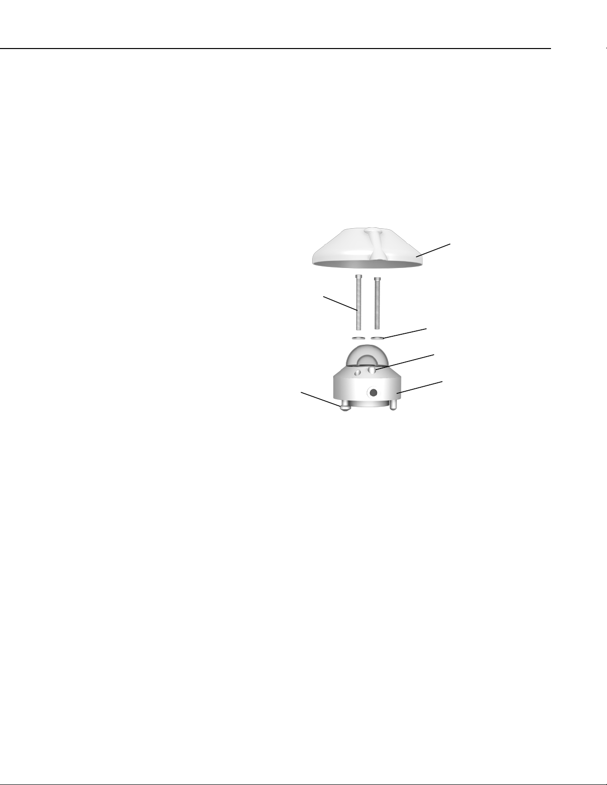
Do the following to level the pyranometer horizontally (see FIGURE 7-1):
1. Attach the mounting stand to the crossarm.
2. Loosely mount the pyranometer on the mounting stand. Do not fully
Appendix C, CVF4 Ventilation Unit (p. C-1), for more
tighten the two mounting screws.
10
Page 21
CMP6, CMP11, and CMP21 Pyranometers
Mounting screws
Levelling screw
Pyranometer
Bubble level
Nylon washers
Sun shield
3. Turn the leveling screws as required to bring the bubble of the level within
the ring.
4. Tighten the mounting screws to secure the assembly in its final position.
Check that the pyranometer is still correctly leveled and adjust as necessary.
5. Attach the white plastic sun screen to the pyranometer.
6. Route the sensor cable along the underside of the crossarm to the
tower/tripod mast, and to the instrument enclosure.
7. Secure the sensor cable to the crossarm and mast using cable ties.
7.2 Wiring
FIGURE 7-1. Exploded view of the pyranometer
To wire an Edlog datalogger, see an older manual at
www.campbellsci.com\old-manuals, or contact a Campbell Scientific
application engineer for assistance.
The cable of the CMP6 and CMP11 has two conductors and a shield. The
cable of the CMP21 has five conductors and a shield. The additional
conductors on the CMP21’s cable are for connecting its internal thermistor. A
schematic for the CMP6, CMP11, and the thermopile of the CMP21 is
provided in Section 7.2.1, CMP6, CMP11, and CMP21 Thermopile Schematic
(p. 12). Wiring for the CMP6 and CMP11 is described in Section 7.2.2, CMP6
and CMP11 Wiring
CMP21 Wiring
(p. 12). Wiring for the CMP21 is described in Section 7.2.3,
(p. 13).
11
Page 22
CMP6, CMP11, and CMP21 Pyranometers
Red
Blue
Black
TABLE 7-1. CMP6 and CMP11 Differential Connections to
⏚
NOTE
White (+)
Black (-)
Shield
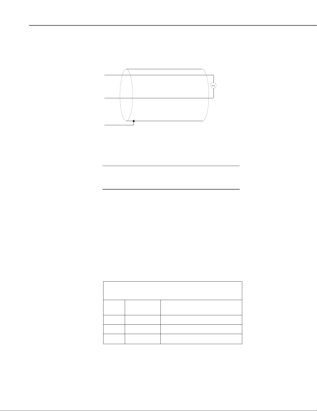
7.2.1 CMP6, CMP11, and CMP21 Thermopile Schematic
A schematic diagram of a CMP6, CMP11, or CMP21 thermopile is shown in
FIGURE 7-2.
FIGURE 7-2. CMP6, CMP11, and CMP21 thermopile detector
schematic
7.2.2 CMP6 and CMP11 Wiring
A CMP6 or CMP11 purchased from Campbell Scientific has
different wiring than a pyranometer purchased directly from Kipp
& Zonen.
The pyranometer is measured using either differential analog channels or
single-ended analog channels.
A differential voltage measurement is recommended because it has better noise
rejection than a single-ended measurement.
Connections to Campbell Scientific dataloggers for a differential measurement
are given in TABLE 7-1. A user-supplied jumper wire should be connected
between the low side of the differential input and ground (AG or ⏚) to keep the
signal in common mode range.
Connections to Campbell Scientific dataloggers for a single-ended
measurement are given in TABLE 7-2.
Campbell Scientific Dataloggers
Color Description
CR9000(X), CR5000,CR3000,
CR1000, CR800, CR6
White Signal (+) Differential Analog High
Black Signal (–) * Differential Analog Low
Shield Shield
* Jumper to ⏚ with user supplied 26 AWG or larger wire.
12
Page 23

CMP6, CMP11, and CMP21 Pyranometers
TABLE 7-2. CMP6 and CMP11 Single-Ended Connections to
⏚
⏚
TABLE 7-3. CMP21 Differential Connections to
⏚
⏚
NOTE
Campbell Scientific Dataloggers
7.2.3 CMP21 Wiring
A CMP21 purchased from Campbell Scientific has different
wiring than a CMP21 purchased directly from Kipp & Zonen.
The CMP21’s pyranometer can be measured using either differential analog
channels or single-ended analog channels. A differential voltage measurement
is recommended because it has better noise rejection than a single-ended
measurement. If a differential channel is not available, a single-ended
measurement can be used.
A single-ended channel and a voltage excitation channel are used to measure
the CMP21’s internal thermistor.
Connections to Campbell Scientific dataloggers for a differential measurement
are given in TABLE 7-3. A user-supplied jumper wire should be connected
between the low side of the differential input and ground (⏚) to keep the signal
in common mode range. Connections to Campbell Scientific dataloggers for a
single-ended measurement are given in TABLE 7-4.
Color Description
White Signal (+) SE Analog
Black Signal (–)
Clear Shield
CR9000(X), CR5000, CR3000,
CR1000, CR800, CR6
Wire
Color
White Pyranometer Sig Differential Analog High
Blue Pyranometer Ref * Differential Analog Low
Yellow Thermistor Volt Excite Voltage excitation port
Black Thermistor Sig Single-ended analog
Brown Thermistor Ref
Clear Shield
* Jumper to ⏚ with user-supplied wire.
Campbell Scientific Dataloggers
Wire Label/
Description
CR9000(X), CR5000, CR3000,
CR1000, CR800, CR6
13
Page 24
CMP6, CMP11, and CMP21 Pyranometers
TABLE 7-4. CMP21 Single-Ended Connections to
⏚
⏚
⏚
NOTE
Campbell Scientific Dataloggers
Wire
Color
White Pyranometer Sig Single-ended analog
Blue Pyranometer Ref
Yellow Thermistor Volt Excite Voltage excitation
Black Thermistor Sig Single-ended analog
Brown Thermistor Ref
Clear Shield
7.3 Programming
Short Cut is the best source for up-to-date datalogger programming code.
Programming code is needed,
If your data acquisition requirements are simple, you can probably create and
maintain a datalogger program exclusively with Short Cut. If your data
acquisition needs are more complex, the files that Short Cut creates are a great
source for programming code to start a new program or add to an existing
custom program.
Wire Label/
Description
CR9000(X), CR5000, CR3000,
CR1000, CR800, CR6
• when creating a program for a new datalogger installation
• when adding sensors to an existing datalogger program
Short Cut cannot edit programs after they are imported and edited
in CRBasic Editor.
A Short Cut tutorial is available in Section 4, Quickstart (p. 2). If you wish to
import Short Cut code into CRBasic Editor to create or add to a customized
program, follow the procedure in Appendix A, Importing Short Cut Code Into
CRBasic Editor
(p. A-1). Programming basics for CRBasic dataloggers are
provided below. Complete program examples for select dataloggers can be
found in Appendix B, Example Programs
7.3.1 Solar Radiation Measurements
Solar radiation can be reported as an average flux density (W•m–2) or daily
total flux density (MJ•m
7-5. Programming examples are given for both average and daily total solar
radiation.
The pyranometers output a low level voltage ranging from 0 to a maximum of
up to 20 mV, in natural light, depending on the calibration factor and radiation
level.
This voltage output is measured using either the VoltDiff() CRBasic
instruction or VoltSE() CRBasic instruction.
–2
(p. B-1).
). The appropriate multipliers are listed in TABLE
14
Page 25

7.3.1.1 Input Range
CAUTION
CMP6, CMP11, and CMP21 Pyranometers
Nearby AC power lines, electric pumps, or motors can be a
source of electrical noise. If the sensor or datalogger is
located in an electrically noisy environment, the
measurement should be made with the 60 or 50 Hz rejection
integration option as shown in the example programs.
–2
The output voltage is usually between 5 and 20 mV per 1000 W•m
. When
estimating the maximum likely value of sensor output a maximum value of
–2
solar radiation of 1100 W•m
horizontal surface. Plane of array irradiances can exceed 1500 W•m
can be used for field measurements on a
–2
.
Select the input range as follows:
7.3.1.2 Multiplier
1. Estimate the maximum expected input voltage by multiplying the
maximum expected irradiance (in W•m
–2
). Divide the answer by 1000 to give the maximum in millivolt
W•m
–2
) by the calibration factor (in µV /
units.
2. Select the smallest input range which is greater than the maximum
expected input voltage. Normally the 50 mV range for the CR3000,
CR5000, or CR9000(X) and the 25 mV or 250 mV range for the CR6,
CR800, CR850, or CR1000 will be suitable. The exact range will depend
on the sensitivity of your individual sensor and the maximum expected
reading. With some dataloggers an autorange option can be used if
measurement time is not critical.
The parameter code for the input range also specifies the measurement
integration time. The slow or 60 Hz rejection integration gives a more noisefree reading. The 250 µs integration takes less power and allows for faster
throughput.
The multiplier converts the millivolt reading to engineering units. The
sensitivity value supplied by the manufacturer gives the output of the sensor as
–2
µV (micro-volts) / W•m
. As the datalogger voltage measurement instructions
give a default output in mV, the following equation should be used to calculate
–2
the multiplier to give the readings in W•m
:
m = 1000/c
Where,
m = multiplier
–2
c = sensor output in µV / W•m
Other units can be used by adjusting the multiplier as shown in TABLE 7-5.
15
Page 26

CMP6, CMP11, and CMP21 Pyranometers
TABLE 7-5. Multipliers Required for Flux Density and Total Fluxes
M = calibration factor with units of W•m–2 / mV
−
=
x
x
V
1
V
1000Res.
Units Multiplier Output Processing
W•m–2
MJ•m–2
kJ•m–2
cal•cm–2
cal • cm
W • hr • m–2
t = datalogger program execution interval in seconds
7.3.1.3 Offset
The offset will normally be fixed at zero as the sensor should output no
significant signal in dark conditions. In practice, because of the nature of
thermopile detector sensors, there will be some offset in dark conditions;
sometimes this offset can give negative light readings. This offset varies with
several factors (e.g., rate of change of sensor temperature), so it cannot be
removed with a fixed offset. Some users may wish to remove small negative
readings by including code after the measurement instructions that sets
negative readings to zero.
–2
• min–1
M Average
M * t * 0.000001 Totalize
t * 0.001
M *
M * t * 0.0239 * 0.001 Totalize
M * 1.434 * 0.001 Average
t / 3600 Totalize
Totalize
7.3.1.4 Output Format Considerations
Over-ranging may be an issue if the measurement values are totalized. Overranging can be prevented when using CRBasic by storing the data in the IEEE4
format.
7.3.2 CMP21 Internal Thermistor Measurement
The thermistor is measured using the BrHalf CRBasic instruction. The value
provided by the half bridge instruction needs to be converted to resistance and
then converted to temperature.
The following equation is used to convert to resistance:
Where,
Vx = the value provided by the half bridge instruction
In CRBasic, the conversion to resistance is entered as a mathematical
expression.
The Steinhart-Hart equation is used to convert resistance to temperature. The
Steinhart-Hart equation for converting resistance to degree Celsius is as
follows:
Temperature = 1/[A + B*LN(resistance) + C*(LN(resistance))^3] - 273.15
16
Page 27
CMP6, CMP11, and CMP21 Pyranometers
Where A, B, and C are coefficients for the Steinhart-Hart equation.
The coefficients for the Steinhart-Hart equation are specific to the thermistor
contained in your CMP21. A calibration certificate that lists these coefficients
is shipped with each CMP21 pyranometer.
In CRBasic, the Steinhart-Hart equation is entered as a mathematical
expression.
8. Maintenance/Troubleshooting
8.1 Maintenance
At regular intervals, physically inspect the pyranometer to ensure that:
• Dome is free of dirt, condensation, and ice (see Section 8.1.1, Cleaning
Domes
• Desiccant granules are orange and opaque (see Section 8.1.2, Changing
the Desiccant
• Mounting is secure.
(p. 17)).
(p. 17)).
• Pyranometer is level (if mounted horizontally).
• Cables are in good condition.
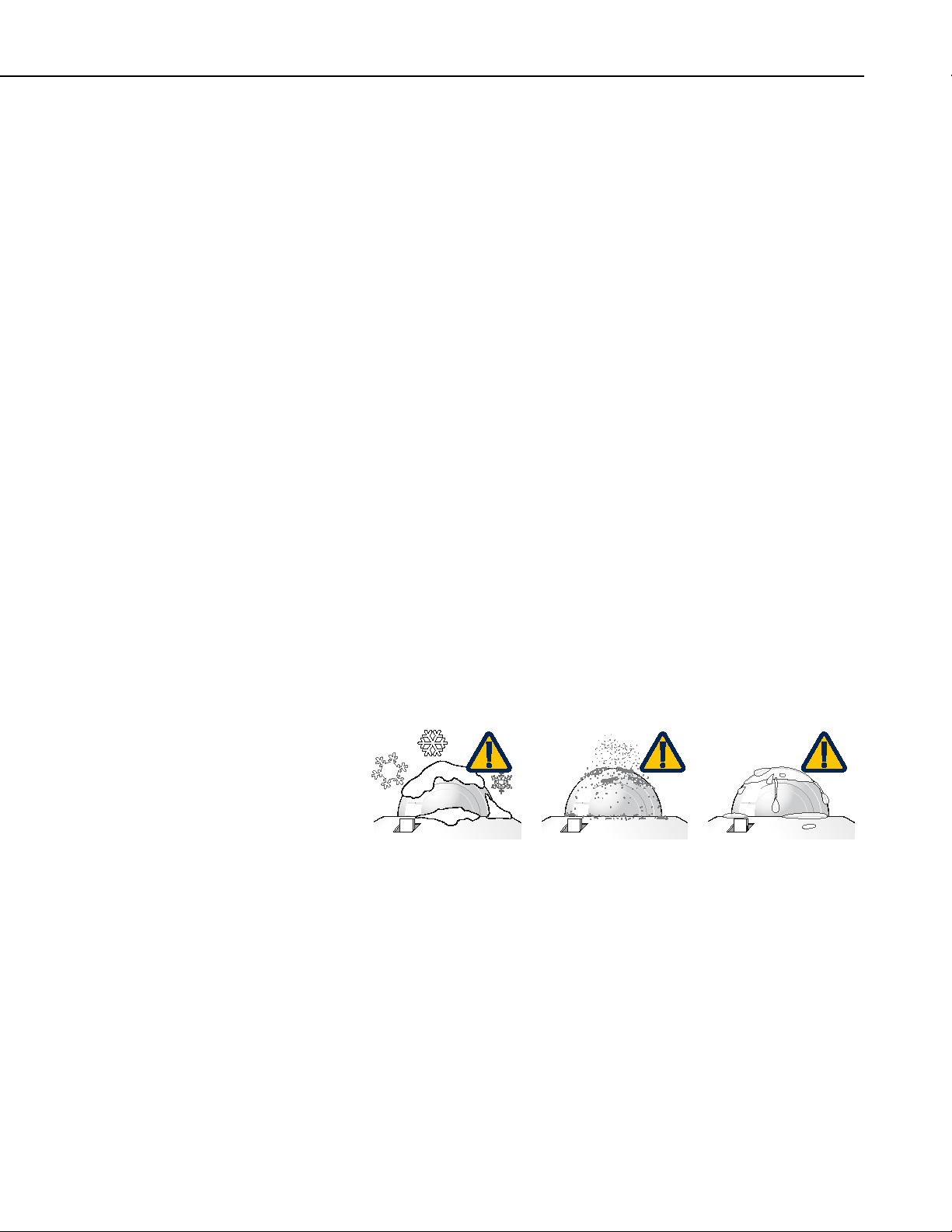
8.1.1 Cleaning Domes
Clean the outer dome at regular intervals (e.g., every week or so). Remove any
accumulated dust, condensation, or ice from the dome and pyranometer body
using a soft cloth dampened with water or alcohol (see FIGURE 8-1).
FIGURE 8-1. Reading is reduced if dome is not dry or clean
8.1.2 Changing the Desiccant
A desiccant-filled drying cartridge prevents dew from forming on the inner
sides of the domes; Campbell Scientific pn 27052 is the replacement desiccant
for this cartridge. The optional CVF4 Heater/Ventilator Unit is also available
to keep the pyranometer dome free from ice and dew (see Appendix C, CVF4
Ventilation Unit
deposition of dust on the pyranometer dome, and therefore reduce the cleaning
interval frequency.
(p. C-1)). In some applications, the CVF4 may also reduce the
17
Page 28

CMP6, CMP11, and CMP21 Pyranometers
The silica gel desiccant granules in the drying cartridge should be orange and
opaque. Replace the desiccant granules when they become translucent
(normally after several months). Refill packs of desiccant are shipped with the
pyranometer and can be purchased from Campbell Scientific. The drying
cartridge uses the content of one refill pack. FIGURE 8-2 shows the
replacement process.
When changing the desiccant, ensure that:
• The surfaces touching the rubber O-ring are clean. Dirt, in combination
with water, can cause corrosion, harming it.
• The rubber O-ring is coated with silicon grease or petroleum jelly. The
grease coating improves the O-ring’s seal.
• The drying cartridge is tightly threaded into the pyranometer’s body.
18
FIGURE 8-2. Changing the desiccant
8.1.3 Check Sensor Output
It is also important to check the data returned from the sensor as it will show
the first indication of a fault. When doing this you should be aware of several
expected phenomena that can cause strange measurements. In particular on
clear, windless nights the outer dome temperature of horizontally placed
pyranometers can fall as low as the dew point temperature of the air, due to
infrared radiation exchange with the cold sky. (The effective sky temperature
can be 30 °C lower than the ground temperature, which results in an infrared
emission of –150 W
be precipitated on the top of the outer dome and can stay there for several hours
in the morning. An ice cap on the dome is a strong diffuser and can increase
the pyranometer signal by up to 50% in the first hours after sunrise.
–2
•m
). If this happens, dew, glazed frost or hoar frost can
Page 29

8.2 Recalibration
The calibration of the pyranometer may drift with time and exposure to
radiation. Recalibration every two years is recommended. The sensor should
be returned to Campbell Scientific for recalibration. A Returned Materials
Authorization (RMA) is required (refer to the Assistance page for more
information).
8.3 Troubleshooting
Symptom: NAN, –9999, or radiation values around 0
1. Check that the sensor is wired to the differential channel specified by the
measurement instruction.
2. Verify that the range code is correct for the datalogger type.
CMP6, CMP11, and CMP21 Pyranometers
3. Measure the impedance across the red and blue sensor wires. This should
be around 100 ohms plus the cable resistance (typically 0.1 ohm•m
the resistance is very low, there may be a short circuit (check the wiring).
Resistances somewhat lower than expected could be due to water ingress
into the sensor or enclosure connectors. If the resistance is infinite, there
is a broken connection (check the wiring).
4. Disconnect the sensor cable and check the voltage output from the sensor.
With the sensor located 8 inches below a 60 W incandescent light bulb the
voltage should be approximately 2.5 mV. No voltage indicates a problem
with the sensor.
Symptom: sensor signal is unrealistically high or low
1. Check that the right calibration factor has been properly entered into the
datalogger program. Please note that each sensor has its own individual
calibration factor.
2. Check the condition of the sensor cable.
Symptom: sensor signal shows unexpected variations
1. Check for the presence of strong sources of electromagnetic radiation
(radar, radio, etc.).
–1
). If
2. Check the condition and the connection of the sensor shield wire.
3. Check the condition of the sensor cable.
19
Page 30

CMP6, CMP11, and CMP21 Pyranometers
20
Page 31

NOTE
Appendix A. Importing Short Cut Code Into CRBasic Editor
This tutorial shows:
• How to import a Short Cut program into a program editor for
additional refinement
• How to import a wiring diagram from Short Cut into the comments of
a custom program
A.1 Importing Short Cut Code into a Program Editor
Short Cut creates files that can be imported into either CRBasic Editor or
Edlog program editor. These files normally reside in the
C:\campbellsci\SCWin folder and have the following extensions:
• .DEF (wiring and memory usage information)
• .CR6 (CR6 datalogger code)
• .CR2 (CR200(X) datalogger code)
• .CR1 (CR1000 datalogger code)
• .CR8 (CR800 datalogger code)
• .CR3 (CR3000 datalogger code)
• .CR5 (CR5000 datalogger code)
• .CR9 (CR9000(X) datalogger code)
Use the following procedure to import Short Cut code into CRBasic Editor
(CR6, CR200(X), CR1000, CR800, CR3000, CR5000 dataloggers).
1. Create the Short Cut program following the procedure in Section 4,
Quickstart
file name used when saving the Short Cut program.
2. Open CRBasic Editor.
3. Click File | Open. Assuming the default paths were used when Short Cut
was installed, navigate to C:\CampbellSci\SCWin folder. The file of
interest has a “.CR6”, “.CR2”, “.CR1”, “.CR8”, “.CR3”, “.CR5”, or
“.CR9” extension, for CR6, CR200(X), CR1000, CR800, CR3000,
CR5000, or CR9000(X) dataloggers, respectively. Select the file and click
Open.
4. Immediately save the file in a folder different from \Campbellsci\SCWin,
or save the file with a different file name.
Once the file is edited with CRBasic Editor, Short Cut can no
longer be used to edit the datalogger program. Change the name
of the program file or move it, or Short Cut may overwrite it next
time it is used.
(p. 2). Finish the program and exit Short Cut. Make note of the
5. The program can now be edited, saved, and sent to the datalogger.
A-1
Page 32

Appendix A. Importing Short Cut Code Into CRBasic Editor
6. Import wiring information to the program by opening the associated .DEF
file. Copy and paste the section beginning with heading “-Wiring for
CRXXX–” into the CRBasic program, usually at the head of the file.
After pasting, edit the information such that a ' character (single quotation
mark) begins each line. This character instructs the datalogger compiler to
ignore the line when compiling the datalogger code.
A-2
Page 33
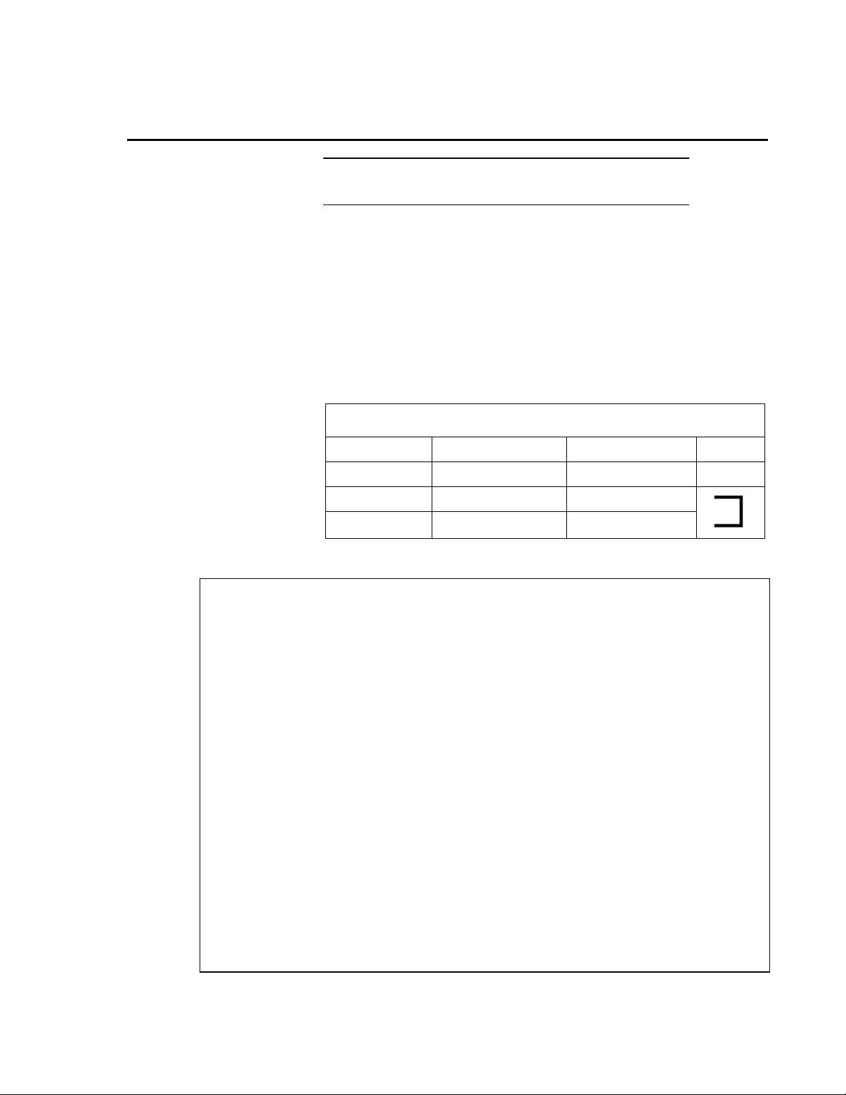
TABLE B-1. CR1000 Wiring for CMP6 Example Program
⏚
NOTE
Appendix B. Example Programs
For an example program for using the CVF4 ventilator, see
Appendix C, CVF4 Ventilation Unit (p. C-1).
B.1 CR1000 Example Program for Measuring a CMP6
Although this example is for the CR1000, other CRBasic dataloggers are
programmed similarly. The following program measures the CMP6 every
second and converts the millivolt output to W•m
–2
14.33 µV / W•m
is used for the example program. Every 10 minutes, the
program outputs the average and standard deviation of the flux (W•m
measurements.
Wiring for this example is given in TABLE B-1.
Wire Color Description CR1000 Jumper*
–2
. A sensor calibration of
–2
)
White Solar Signal (+) 1H
Black Solar Signal (–) 1L
Clear Shield
* Jumper 1L to ⏚ with user-supplied 26 AWG or larger wire.
'CR1000 Series Datalogger
Public PTemp
Public Batt_Volt
Public CMP6_Irr
Units CMP6_Irr = W/m2
DataTable (TenMin,1,-1)
DataInterval (0,1,Min,4)
Minimum (1,Batt_Volt,FP2,0,False)
Sample (1,PTemp,FP2)
Average (1,CMP6_Irr,FP2,False)
StdDev (1,CMP6_Irr,FP2,False)
EndTable
BeginProg
Scan (1,Sec,0,0)
'Measure the Battery Voltage and Panel Temperature
PanelTemp (PTemp,250)
Battery (Batt_Volt)
'Measure the CMP6
VoltDiff (CMP6_Irr,1,mV25C,1,True ,10000,_60Hz,1000/14.33,0)
CallTable TenMin
NextScan
EndProg
B-1
Page 34
Appendix B. Example Programs
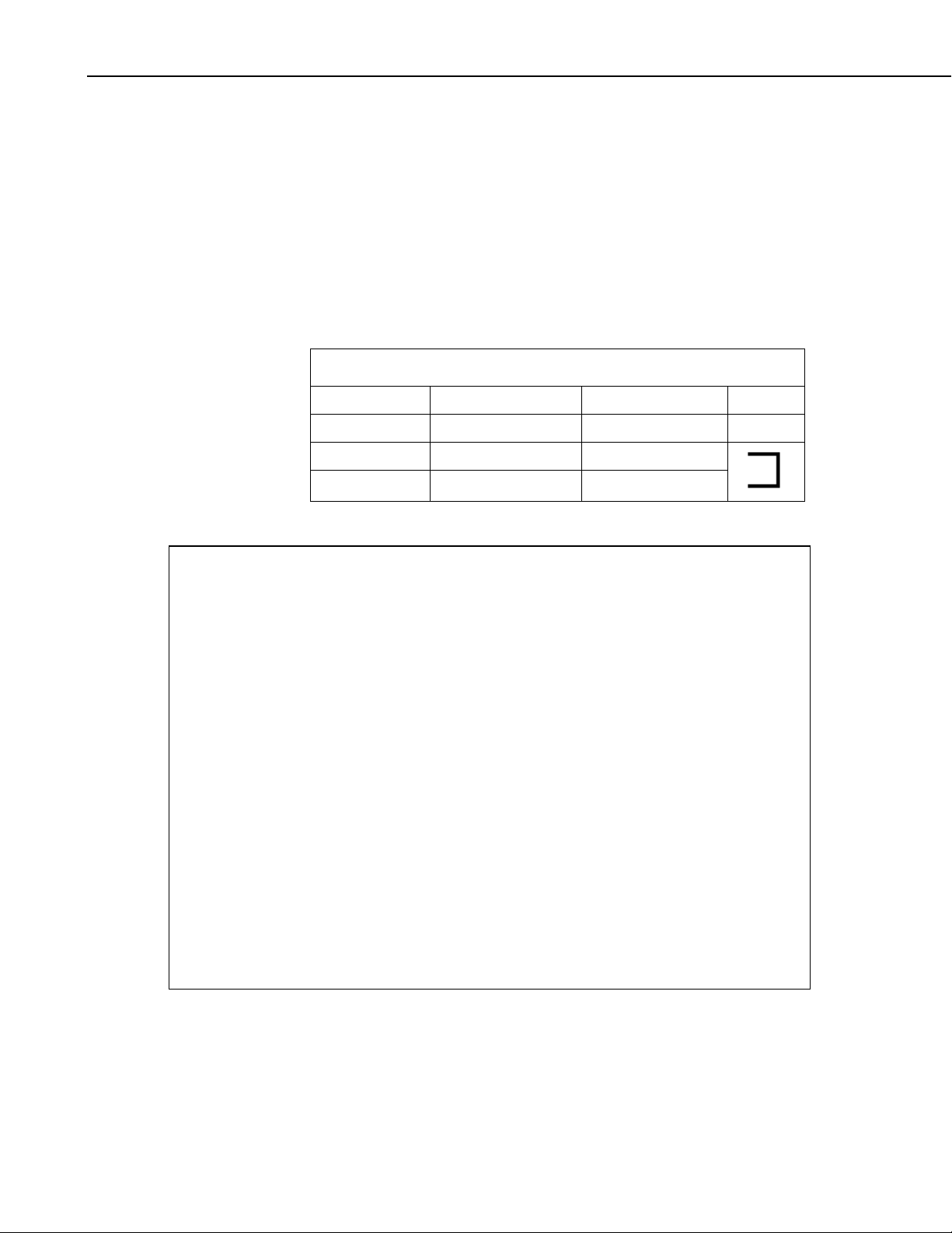
TABLE B-2. CR1000 Wiring for CMP11 Example Program
⏚
B.2 CR1000 Example Program for Measuring a
CMP11
Although this example is for the CR1000, other CRBasic dataloggers are
programmed similarly. The following program measures the CMP11 every
second and converts the millivolt output to W•m
–2
8.55 µV / W•m
is used for the example program. Every 10 minutes, the
program outputs the average and standard deviation of the flux (W•m
measurements.
Wiring for this example is given in TABLE B-2.
Wire Color Description CR1000 Jumper*
White Solar Signal (+) 2H
Black Solar Signal (–) 2L
–2
. A sensor calibration of
–2
)
Clear Shield
* Jumper 2L to ⏚ with user-supplied 26 AWG or larger wire.
'CR1000 Series Datalogger
Public PTemp
Public Batt_Volt
Public CMP11_Irr
Units CMP11_Irr = W/m2
DataTable (TenMin,1,-1)
DataInterval (0,1,Min,4)
Minimum (1,Batt_Volt,FP2,0,False)
Sample (1,PTemp,FP2)
Average (1,CMP11_Irr,FP2,False)
StdDev (1,CMP11_Irr,FP2,False)
EndTable
BeginProg
Scan (1,Sec,0,0)
'Measure the Battery Voltage and Panel Temperature
PanelTemp (PTemp,250)
Battery (Batt_Volt)
'Measure the CMP11
VoltDiff (CMP11_Irr,1,mV25C,2,True ,10000,_60Hz,1000/8.55,0)
CallTable TenMin
NextScan
EndProg
B-2
Page 35
Appendix B. Example Programs
TABLE B-3. CR1000 Wiring for CMP21 Example Program
⏚
⏚
⏚
B.3 CR1000 Example Program for Measuring a
CMP21
Although this example is for the CR1000, other CRBasic dataloggers are
programmed similarly. The following program measures the CMP21 every
second. It converts the pyranometer’s millivolt output to W•m
–2
pyranometer calibration of 8.65 µV / W•m
is used for the example program.
The resistance of the internal thermistor is converted to degree Celsius and then
to Kelvin. Every 10 minutes, the program outputs the average and standard
–2
deviation of the flux (W•m
) measurements and temperature measurements.
Wiring for this example is given in TABLE B-3.
Wire Color Description CR1000 Jumper*
White Solar Signal (+) 3H
Blue Solar Signal (–) 3L
–2
. A
Yellow Voltage Excitation VX1
Black Temp Signal 15 SE
Brown Signal Reference
Clear Shield
* Jumper 3L to ⏚ with user-supplied 26 AWG or larger wire.
'CR1000 Series Datalogger
Public PTemp
Public Batt_Volt
Public CMP21_Irr
Public CMP21_T_C
Public CMP21_T_K
Dim Rs,Vs_Vx
Units CMP21_Irr = W/m2
Units CMP21_T_C = Degrees C
Units CMP21_T_K = Degrees K
DataTable (TenMin,1,-1)
DataInterval (0,1,Min,8)
Minimum (1,Batt_Volt,FP2,0,False)
Sample (1,PTemp,FP2)
Average (1,CMP21_Irr,FP2,False)
StdDev (1,CMP21_Irr,FP2,False)
Average (1,CMP21_T_C,FP2,False)
StdDev (1,CMP21_T_C,FP2,False)
Average (1,CMP21_T_K,FP2,False)
StdDev (1,CMP21_T_K,FP2,False)
EndTable
BeginProg
Scan (1,Sec,0,0)
B-3
Page 36

Appendix B. Example Programs
‘Measure the Battery Voltage and Panel Temperature
PanelTemp (PTemp,250)
Battery (Batt_Volt)
‘Measure the CMP21 pyranometer
VoltDiff (CMP21_Irr,1,mV25C,3,True,10000,_60Hz,1000/8.65,0)
'CMP21 Thermistor Measurement
BrHalf (Vs_Vx,1,mV5000,15,Vx1,1,2500,True ,0,250,1.0,0)
Rs = 1000*(Vs_Vx/(1-Vs_Vx))
CMP21_T_C = 1/(1.0295e-3+2.391e-4*LN(Rs)+1.568e-7*(LN(Rs))^3)-273.15
'Convert CMP21 temp to Kelvin.
CMP21_T_K = CMP21_T_C+273.15
CallTable TenMin
NextScan
EndProg
B-4
Page 37

NOTE
Appendix C. CVF4 Ventilation Unit
C.1 General Information
Ventilation of radiometers improves the reliability and accuracy of the
measurement by reducing dust, raindrops and dew on the dome. With
thermopile-based instruments ventilation stabilizes the temperature of the
radiometer and suppresses thermal offsets. The integrated heater can be used
to disperse precipitation and melt frost, or even melt snow and ice in cold
climates.
CVF4 is a low power, low maintenance ventilation unit. The only part that
needs maintenance is the removable air inlet filter, which should be checked at
regular intervals and cleaned or replaced when necessary.
The flow that the CVF4 creates is unique. At the top of the pyranometer dome
the flow is very high and it swirls to improve the air distribution over the dome.
The position of the heaters and the new cover material ensures that only half
the heating power is needed to melt frost and snow compared to older
ventilation units.
CVF4 is designed to be used with Kipp & Zonen’s:
• CMP / SMP pyranometers
• CGR 4 pyrgeometer
• CUV 5 total UV radiometer
CVF4 can be mounted on the 2AP and SOLYS 2 sun trackers.
CVF4 replaces the successful and widely used CVF3 ventilation unit.
The CVF4 is meant to run continuously. The heater can either be switched on
permanently for cold regions or be switched by a Campbell Scientific
datalogger to remove dew in the morning and be switched off afterwards. In
that case, the heater could operate for a period of time before and after sunrise.
This saves power in situations where power is limited, such as PV operated
systems.
The CVF4 is manufactured by Kipp & Zonen and cabled by
Campbell Scientific. The wiring of a CVF4 purchased from
Campbell Scientific is different than the wiring of a CVF4
purchased directly from Kipp & Zonen.
C.2 CVF4 Components
FIGURE C-1 and FIGURE C-2 show the components of the CVF4. It is
shipped with a cover, power cable, eight washers, four screws, Allen wrench,
and five spare filters (FIGURE C-3).
C-1
Page 38

Appendix C. CVF4 Ventilation Unit
Heater
Ventilator
Cover Nut
Pyranometer
Mounting Holes
Heater
CVF4 Cable
Connector
Pyranometer
Cover Nut
Connector Box
Mounting Feet
Cover Nut
Mounting Feet
Filter Cover
Cable Slot
FIGURE C-1. CVF4 Components (top view, no cover)
FIGURE C-2. CVF4 Components (bottom view)
C-2
Page 39
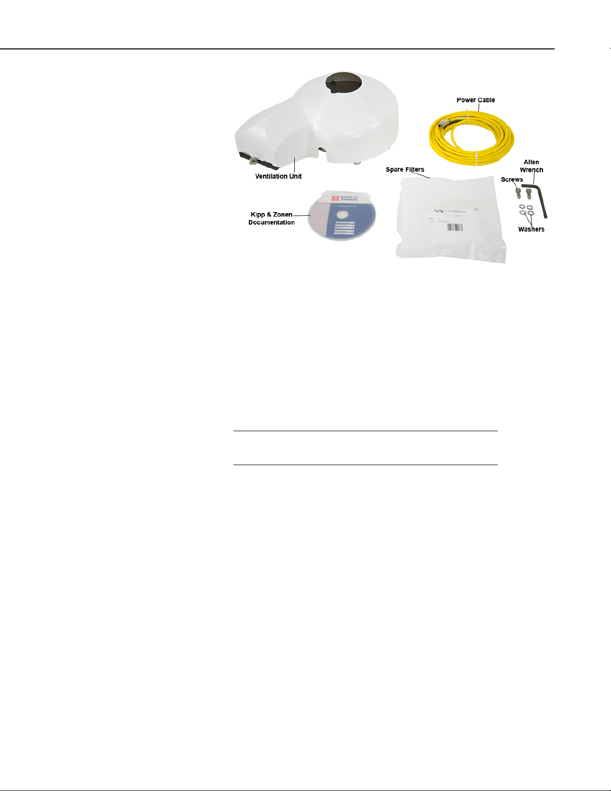
FIGURE C-3. CVF4 Ventilation Unit and Ships With Kit
NOTE
C.3 CVF4 Installation
Appendix C. CVF4 Ventilation Unit
Siting information provided in Section 4.1, Siting (p. 2), is pertinent when using
the CVF4 heater/ventilation.
1. CVF4 heater/ventilator unit includes the heater/ventilator unit, white
cover, cable, and mounting hardware. The CVF4 is mounted to a crossarm
using the 31153 mount and either the CM220 Right-Angle Mounting
Bracket or the 17953 1-inch by 1-inch NU-RAIL.
Refer to the Kipp & Zonen Instruction Manual if mounting the
CVF4 to a SOLYS 2 Solar Tracker or to a CM 121C Shadow Ring.
Tools required for mounting to a tripod or tower are:
• Small and medium Phillips screwdrivers
• 5/16 inch, 1/2 inch open end wrenches
• 5/32 inch Allen wrench
• Tape measure
• UV-resistant wire ties
• Side-cut pliers
• Step ladder
C-3
Page 40
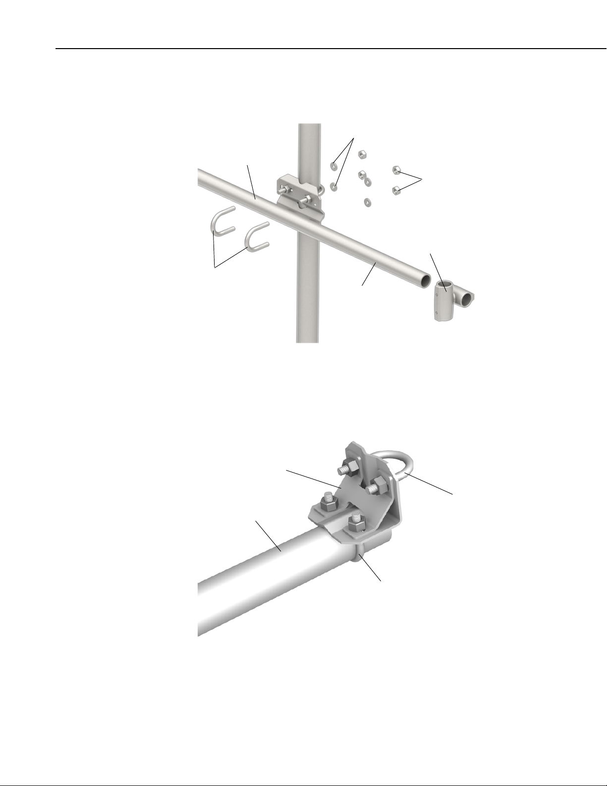
Appendix C. CVF4 Ventilation Unit
U-bolt Washers
CM210 Bracket
crossarm)
U-bolt Nuts
17953
NU-RAIL
CM200-series
Crossarm
U-bolts
CM220 Right
Angle Bracket
U-bolt for Attaching the
U-bolt for Attaching
the Crossarm
CM200-Series
Crossarm
To install, do the following:
1. Mount the crossarm to the tripod or tower (FIGURE C-4).
(included with
FIGURE C-4. Crossarm and 17593 NU-RAIL Mounted to Mast
(exploded view)
2. Attach the CM220 Right-Angle Mounting Bracket (FIGURE C-5) or a
17953 1 in. by 1 in. NU-RAIL (FIGURE C-4) to the crossarm.
31153 Mounting Stand
C-4
FIGURE C-5. CM220 Right-Angle Mounting Bracket attached to
CM200-series crossarm
Page 41
Appendix C. CVF4 Ventilation Unit
Pyranometer
Nylon Washer
Level
Cable Notch
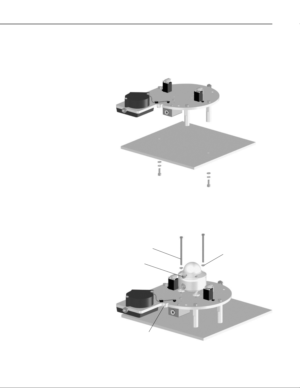
3. Place the CVF4 (without the white plastic cover) on the 31153 with the fan
hanging over the edge of the plate and with the mounting feet lined up
with the mounting holes.
4. Fasten the CVF4’s feet to the 31153 using the supplied washers and
screws (FIGURE C-6).
FIGURE C-6. Mounting CVF4 feet to a mounting stand
5. Loosely mount the pyranometer on the CVF4 using the mounting screws
and washers. Do not fully tighten the pyranometer’s two mounting screws
(FIGURE C-7).
Mounting Screw
FIGURE C-7. Mounting the pyranometer to the CVF4
C-5
Page 42

Appendix C. CVF4 Ventilation Unit
6. Turn the pyranometer’s leveling screws as required to bring the bubble of
7. Tighten the pyranometer’s mounting screws to secure the assembly in its
8. Route the pyranometer’s cable through the cable notch.
9. Fit the white cover onto the CVF4 and secure it with the cover nuts (see
the level within the ring.
final position. Check that the pyranometer is still correctly leveled and
adjust as necessary.
FIGURE C-8).
C-6
FIGURE C-8. CVF4 Mounted to 31153 Stand (pyranometer not shown)
10. Attach the power cable to the CVF4 connector.
11. Route the cables along the underside of the crossarm to the tower/tripod
mast, and to the instrument enclosure.
12. Secure the cables to the crossarm and mast using cable ties.
Page 43
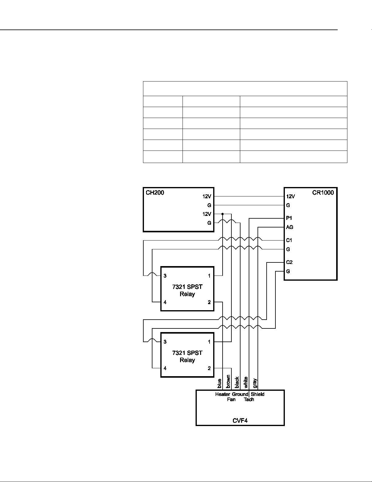
C.4 Wiring
TABLE C-1. CVF4 Wiring
⏚
Appendix C. CVF4 Ventilation Unit
Wiring of the CVF4 is shown in TABLE C-1. Refer to Section 7.2, Wiring (p.
11)
, for information about wiring the pyranometer.
Wire Color Description Connection
Brown Ventilator Power +12V on Power Supply
Blue Heater Power +12V on Power Supply
Black Power Ground G on Power Supply
White Tachometer Signal Datalogger pulse channel or control port
Clear Shield
C.4.1 Implementation Example
on datalogger
C-7
Page 44

Appendix C. CVF4 Ventilation Unit
C.5 CVF4 Example Program
'CR1000 Series Datalogger
'Example program for CVF4
'Declare Public Variables
Public PTemp, batt_volt
Public GH_Irradiance_CMP11
Public CVF4_Tach
Public SolarPos(5)
Public Airtemp
Public TimeArray(9)
'Declare Constants
Const CMP11_Sensitivity = 12.5
Const Latitude = 41.767561
Const Longitude = -111.85592
Const Altitude = 1358
'Define Aliases
Alias SolarPos(1) = SolarAzimuth
Alias SolarPos(2) = SunElevation
Alias SolarPos(3) = HourAngle
Alias SolarPos(4) = Declination
Alias SolarPos(5) = AirMass
'Define Data Tables
DataTable (Ten_Min,1,-1)
DataInterval (0,10,Min,10)
Minimum (1,batt_volt,FP2,0,False)
Sample (1,PTemp,FP2)
Average (1,GH_Irradiance_CMP11,FP2,False)
StdDev(1,GH_Irradiance_CMP11,FP2,False)
Average (1,CVF4_Tach,FP2,False)
EndTable
'Main Program
BeginProg
Scan (1,Sec,0,0)
PanelTemp (PTemp,250) 'Measure wire panel temperature
Battery (batt_volt) 'Measure battery voltage
'Retrieve the current time for use in the Solar Position Calculation
'-------------------------------------------------------------------------- RealTime (TimeArray())
'---------------------------------------------------------------------------
'Measure Air Temperature
'-------------------------------------------------------------------------- Therm109 (Airtemp,1,3,Vx1,0,250,1.0,0)
'---------------------------------------------------------------------------
'Calculate the Solar Position
'---------------------------------------------------------------------------
SolarPosition (SolarPos(),TimeArray,0,Latitude,Longitude,Altitude,-1,Airtemp)
'---------------------------------------------------------------------------
'Measure GH Irradiance with CMP11 Pyranometer
'-------------------------------------------------------------------------- VoltDiff(GH_Irradiance_CMP11,1,mV25,1,True,0,_60Hz,1000/CMP11_Sensitivity,0)
'---------------------------------------------------------------------------
C-8
Page 45

Appendix C. CVF4 Ventilation Unit
NOTE
NOTE
'Measure CVF4 Tachometer Output
'-------------------------------------------------------------------------- PulseCount (CVF4_Tach,1,1 ,0,1,1.0,0)
CVF4_Tach = CVF4_Tach*(60/2) 'convert to RPM, CVF4 outputs two pulses per revolution
'---------------------------------------------------------------------------
'Control the CVF4 Heater
'-------------------------------------------------------------------------- If SunElevation > -10 AND SunElevation < 10 Then
PortSet (1,1)
Else
PortSet (1,0)
EndIf
'--------------------------------------------------------------------------CallTable Ten_Min
NextScan
EndProg
C.6 CVF4 Heater/Ventilator Maintenance
1. Refer to Section 8.1, Maintenance (p. 17), for the pyranometer’s
maintenance.
2. Inspect the area directly under the fan to ensure that it is free from leaves,
snow, or other obstructions that can inhibit air flow.
3. Regularly inspect the fan inlet by unclipping the cover. For optimal air
flow, make sure the diagonal line on the filter cover is in line with the
diagonal line on the ventilator (FIGURE C-9). The filter cover clicks back
on the ventilator.
4. Clean or replace filters typically every 6 months.
The filters may need to be cleaned or replaced more frequently
depending on the site and air pollution.
5. If desired, clean the plastic cover using water and a brush or cloth.
Discoloration of the plastic cover does not affect the operation of
the CVF4. The cover only needs to be cleaned for aesthetic
reasons.
C-9
Page 46

Appendix C. CVF4 Ventilation Unit
Ventilator
Diagonal Line
Cover Diagonal Line
Filter
Filter Cover
FIGURE C-9. CVF4 filter replacement, pn 31435
C-10
Page 47

Page 48

Campbell Scientific Companies
Campbell Scientific, Inc. (CSI)
815 West 1800 North
Logan, Utah 84321
UNITED STATES
www.campbellsci.com • info@campbellsci.com
Campbell Scientific Africa Pty. Ltd. (CSAf)
PO Box 2450
Somerset West 7129
SOUTH AFRICA
www.csafrica.co.za • cleroux@csafrica.co.za
Campbell Scientific Australia Pty. Ltd. (CSA)
PO Box 8108
Garbutt Post Shop QLD 4814
AUSTRALIA
www.campbellsci.com.au • info@campbellsci.com.au
Campbell Scientific (Beijing) Co., Ltd.
8B16, Floor 8 Tower B, Hanwei Plaza
7 Guanghua Road
Chaoyang, Beijing 100004
P.R. CHINA
www.campbellsci.com • info@campbellsci.com.cn
Campbell Scientific do Brasil Ltda. (CSB)
Rua Apinagés, nbr. 2018 ─ Perdizes
CEP: 01258-00 ─ São Paulo ─ SP
BRASIL
www.campbellsci.com.br • vendas@campbellsci.com.br
Campbell Scientific Canada Corp. (CSC)
14532 – 131 Avenue NW
Edmonton AB T5L 4X4
CANADA
www.campbellsci.ca • dataloggers@campbellsci.ca
Please visit www.campbellsci.com to obtain contact information for your local US or international representative.
Campbell Scientific Centro Caribe S.A. (CSCC)
300 N Cementerio, Edificio Breller
Santo Domingo, Heredia 40305
COSTA RICA
www.campbellsci.cc • info@campbellsci.cc
Campbell Scientific Ltd. (CSL)
Campbell Park
80 Hathern Road
Shepshed, Loughborough LE12 9GX
UNITED KINGDOM
www.campbellsci.co.uk • sales@campbellsci.co.uk
Campbell Scientific Ltd. (CSL France)
3 Avenue de la Division Leclerc
92160 ANTONY
FRANCE
www.campbellsci.fr • info@campbellsci.fr
Campbell Scientific Ltd. (CSL Germany)
Fahrenheitstraße 13
28359 Bremen
GERMANY
www.campbellsci.de • info@campbellsci.de
Campbell Scientific Spain, S. L. (CSL Spain)
Avda. Pompeu Fabra 7-9, local 1
08024 Barcelona
SPAIN
www.campbellsci.es • info@campbellsci.es
 Loading...