

Page 1
Tripod Installation Manual
Models CM110, CM115, CM120
Revision: 5/10
Copyright © 2005-2010
Campbell Scientific, Inc.
Page 2

Warranty and Assistance
The CM110, CM115, AND CM120 are warranted by CAMPBELL
SCIENTIFIC, INC. to be free from defects in materials and workmanship
under normal use and service for twelve (12) months from date of shipment
unless specified otherwise. Batteries have no warranty. CAMPBELL
SCIENTIFIC, INC.'s obligation under this warranty is limited to repairing or
replacing (at CAMPBELL SCIENTIFIC, INC.'s option) defective products.
The customer shall assume all costs of removing, reinstalling, and shipping
defective products to CAMPBELL SCIENTIFIC, INC. CAMPBELL
SCIENTIFIC, INC. will return such products by surface carrier prepaid. This
warranty shall not apply to any CAMPBELL SCIENTIFIC, INC. products
which have been subjected to modification, misuse, neglect, accidents of
nature, or shipping damage. This warranty is in lieu of all other warranties,
expressed or implied, including warranties of merchantability or fitness for a
particular purpose. CAMPBELL SCIENTIFIC, INC. is not liable for special,
indirect, incidental, or consequential damages.
Products may not be returned without prior authorization. The following
contact information is for US and International customers residing in countries
served by Campbell Scientific, Inc. directly. Affiliate companies handle
repairs for customers within their territories. Please visit
www.campbellsci.com to determine which Campbell Scientific company
serves your country.
To obtain a Returned Materials Authorization (RMA), contact CAMPBELL
SCIENTIFIC, INC., phone (435) 753-2342. After an applications engineer
determines the nature of the problem, an RMA number will be issued. Please
write this number clearly on the outside of the shipping container.
CAMPBELL SCIENTIFIC's shipping address is:
CAMPBELL SCIENTIFIC, INC.
RMA#_____
815 West 1800 North
Logan, Utah 84321-1784
For all returns, the customer must fill out a “Declaration of Hazardous Material
and Decontamination” form and comply with the requirements specified in it.
The form is available from our website at
completed form must be either emailed to repair@campbellsci.com
435-750-9579. Campbell Scientific will not process any returns until we
receive this form. If the form is not received within three days of product
receipt or is incomplete, the product will be returned to the customer at the
customer’s expense. Campbell Scientific reserves the right to refuse service on
products that were exposed to contaminants that may cause health or safety
concerns for our employees.
www.campbellsci.com/repair
. A
or faxed to
Page 3

Tripod Installation Table of Contents
PDF viewers note: These page numbers refer to the printed version of this document. Use
the Adobe Acrobat® bookmarks tab for links to specific sections.
1. General .........................................................................1
2. Specifications ..............................................................2
3. Tools List (for tripod, mast and crossarm) ...............3
4. Tripod Components.....................................................3
5. Tripod Installation........................................................4
5.1 Tripod Base...............................................................................................4
5.2 Mast..........................................................................................................5
5.3 Installing the Guy Kit ...............................................................................9
5.3.1 Guy Duckbill Anchor Kits............................................................11
5.3.2 Lowering Mast after Attaching Guy Wires...................................13
5.4 Staking the Tripod Feet ..........................................................................14
5.5 Tripod Grounding...................................................................................15
5.6 Crossarm Attachment .............................................................................17
5.7 Enclosure Attachment.............................................................................17
5.7.1 Enclosure Mounting to Tripod Mast.............................................17
5.7.2 Enclosure Mounting to Tripod Leg...............................................18
6. Mounting Brackets ....................................................20
6.1 CM210 Crossarm Mounting Kit.............................................................20
6.2 CM216 Mast Mounting Kit....................................................................21
6.3 CM220 Right Angle Mounting Kit.........................................................22
6.4 CM225 Pyranometer Mounting Stand....................................................23
6.5 CM230 Adjustable Angle Mounting Kit................................................24
6.6 CM235 Magnetic Mounting Stand.........................................................25
6.7 RM Young Gill Radiation Shields..........................................................26
Appendix
A. Tripod Tote Bag....................................................... A-1
Figures
1-1. CM110 Tripod with Optional Guy Kit....................................................1
2-1. 60-Degree Guy Angle .............................................................................3
4-1. Tripod Components.................................................................................4
5-1. Tripod Leg, Slide Collar Components.....................................................5
i
Page 4

Tripod Installation Table of Contents
5-2. Tripod Mast and Insert ........................................................................... 6
5-3. Mast Attachment to Tripod Base............................................................ 7
5-4. Mast Lock Bracket.................................................................................. 8
5-5. Guy Collar .............................................................................................. 9
5-6. Guy Cinch and Lever Arm ................................................................... 10
5-7. Mechanical Drawing of Guy Hook and Case....................................... 11
5-8. Duckbill Guy Anchor ........................................................................... 12
5-9. Top View and Guy Anchor Layout...................................................... 13
5-10. Staking the Tripod Feet ...................................................................... 14
5-11. Ground Rod and Clamp......................................................................15
5-12. Lightning Rod and Tripod Grounding Lug ........................................ 16
5-13. CM204 Crossarm................................................................................ 17
5-14. Enclosure with the –MM Bracket ....................................................... 18
5-15. Enclosure with the –LM Bracket........................................................ 19
6-1. CM210 Crossarm Mounting Kit...........................................................20
6-2. CM216 Mast Mounting Kit.................................................................. 21
6-3. CM220 Right Angle Mounting Kit....................................................... 22
6-4. CM225 Pyranometer Mounting Stand.................................................. 23
6-5. CM230 Adjustable Angle Mounting Kit.............................................. 24
6-6. CM235 Magnetic Mounting Stand....................................................... 25
6-7. RM Young Gill Radiation Shield......................................................... 26
ii
Page 5
Tripod Installation Manual Models CM110, CM115, CM120
1. General
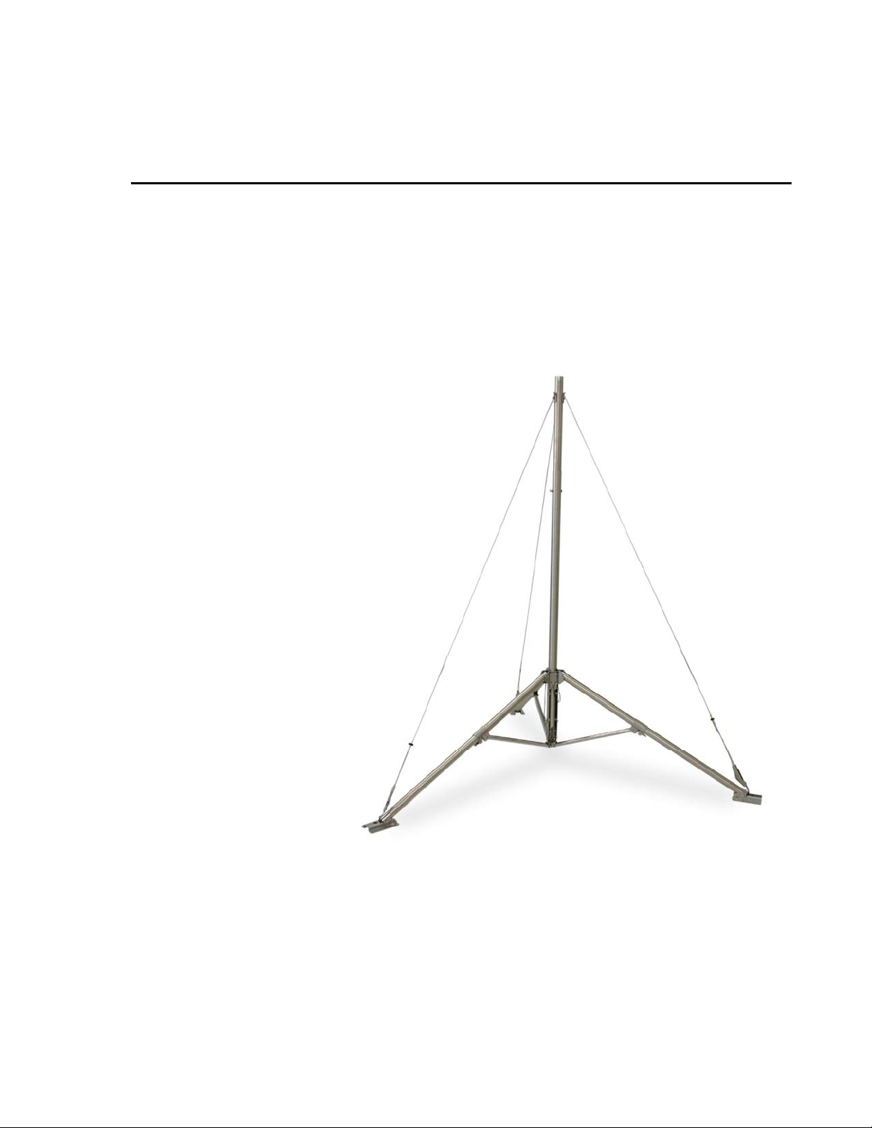
The CM110 (10 feet), CM115 (15 feet), and CM120 (20 feet) tripods are
corrosion-resistant stainless steel instrument mounts that support the
attachment of sensors, solar panels, and environmental enclosures. A guy kit is
included with the CM115 and CM120 models, and is an option for the CM110.
A durable Tripod Tote Bag is available as an option.
FIGURE 1-1. CM110 Tripod with Optional Guy Kit
1
Page 6

Tripod Installation Manual Models CM110, CM115, CM120
2. Specifications
Height w/mast insert: 10’ (3 m) 15.5’ (4.7 m) 21.0’ (6.4 m)
Weight: 34 lbs (15 kg) 40 lbs (18 kg) 46 lbs (21 kg)
Base diameter w/legs extended: 7 ft (2 m) 7 ft (2 m) 7 ft (2 m)
Dimensions of collapsed tripo d: 6” x 6” x 57”
Vertical load limit: 100 lb (45 kg) 100 lb (45 kg) 100 lb (45 kg)
Mast description
Number of sections: 1 2 3
Length: 4.6’ (1.4m) 9.3’ (2.8 m) 14.0’ (4.3 m)
Length w/insert: 8.6’ (2.6 m) 13.3’ (4.1 m) 18.0’ (5.5 m)
OD: 1.9” (4.8 cm) 1.9” (4.8 cm) 1.9” (4.8 cm)
Insert OD: 1.75” (4.45 cm) 1.75” (4.45 cm) 1.75” (4.45 cm)
Mounting hole in tripod foot: 0.75” diameter hole
Wind load recommendations
Sustained wind (mph): *75 (unguyed)
CM110
(15 x 15 x 145 cm)
for user-supplied
0.5” J-bolts
80 (guyed at feet)
CM115 (see note 3)
6” x 6” x 57”
(15 x 15 x 145 cm)
0.75” diameter hole
for user-supplied
0.5” J-bolts
*56.25 (guyed at feet)
75 (guyed at 60°)
CM120 (see note 3)
6” x 6: x 57”
(15 x 15 x 145 cm)
0.75” diameter hole
for user-supplied
0.5” J-bolts
*42.25 (guyed at feet)
65 (guyed at 60°)
Gust tolerance (mph): 95 (unguyed)
100 (guyed at feet)
Tote bag dimensions: 8” (20 cm) diameter,
60” (152 cm) length
71.25 (guyed at feet)
95 (guyed at 60°)
8” (20 cm) diameter,
60” (152 cm) length
55.25 (guyed at feet)
85 (guyed at 60°)
8” (20 cm) diameter,
60” (152 cm) length
2
Page 7
*Anchors must hold at least
400 lbf in both x, y axis
Tripod Installation Manual Models CM110, CM115, CM120
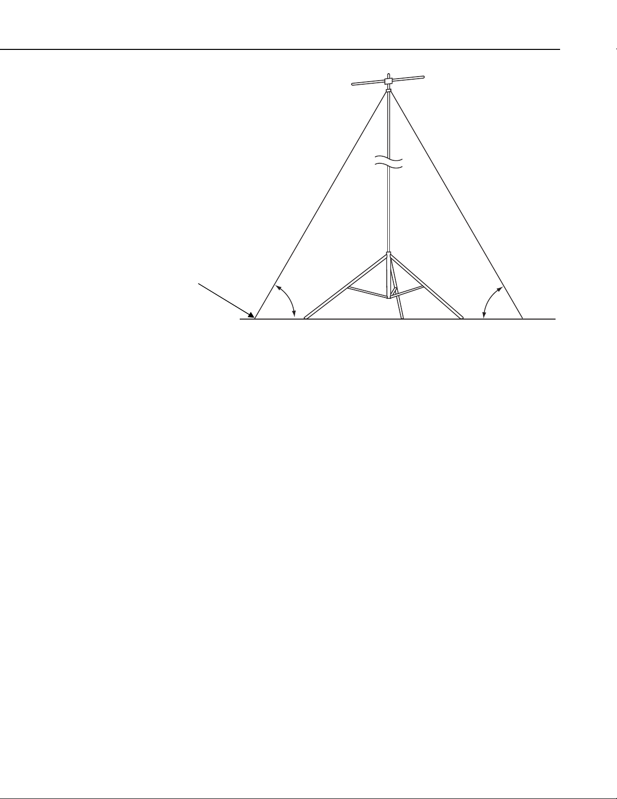
60º
60º
FIGURE 2-1. 60-Degree Guy Angle
3. Tools List (for tripod, mast and crossarm)
1/2” and 7/16” open end wrenches
adjustable wrench
socket wrench with 1/2”and 7/16” deep sockets (optional)
Phillips head screw driver (medium)
Straight bit screwdriver (large)
12” torpedo level
side-cut pliers
pencil
tape measure
compass and site declination angle
shovel
sledge hammer (for driving ground rod and stakes)
step ladder
4. Tripod Components
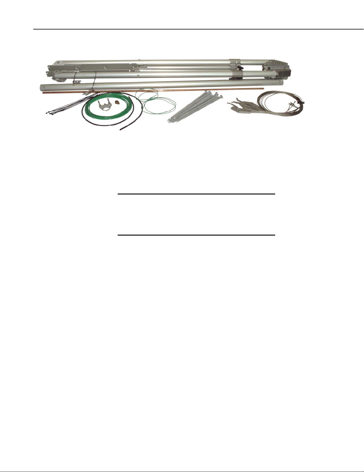
Figure 4-1 shows the tripod components packaged for shipment. The tripod
base is packaged with the mast, ground rod, lightning rod and (6 ) stakes. The
ground rod clamp, lightning rod, and grounding wires are enclosed in a bag.
The guy kit (optional for the CM110), and tripod tote bag (optional) are
packaged separately. The CM115 and CM120 tripods include additiona l mast
sections. A diagram showing how to stow the components inside the tote bag
is shown in Appendix A.
3
Page 8
Tripod Installation Manual Models CM110, CM115, CM120
FIGURE 4-1. Tripod Components
5. Tripod Installation
5.1 Tripod Base
WARNING
Tripod installation near power lines is dangerous. The
minimum safe recommended distance from overhead
power lines is 2 times the height of the tripod and mast
combined. Call Blue Stakes to locate buried utilities
prior to installation.
All three models of tripods use the same tripod base. Each leg is adjustable,
which allows the tripod to be adjusted for non-level terrain.
Prepare the area where the tripod will be installed. The tripod requires an area
approximately 7 feet in diameter. Natural vegetation and the ground surface
should be disturbed as little as possible, but brush and tall weeds should be
removed.
Stand the tripod base up on end, and rotate the feet perpendicular to the legs.
Each leg has a slide collar and T-knob with a spring loaded pin that locks into
holes located on the underside of the leg as shown in Figure 5-1.
Extend each leg until the pin engages in a hole (depress the tab to disengage
the pin from a hole). With the legs extended, orient the tripod so that the open
channel of the tripod base faces North. The tripod is typically plumbed after
the mast has been installed, as described in Section 5.2.
4
Page 9
Tripod Installation Manual Models CM110, CM115, CM120
Holes for Pins
Slide Collar
5.2 Mast
Spring-Loaded Pin
T-Knob
FIGURE 5-1. Tripod Leg, Slide Collar Components
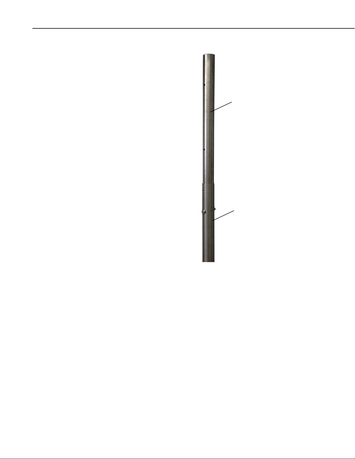
The CM110, CM115 and CM120 tripods have one, two or three mast sections
respectively. The top mast section has a 48” long insert with a series of holes
that can be extended to lengthen the mast. Remove the bolt that secures the
insert to the inside of the mast, and slide the insert out from the mast to see the
different hole locations. Slide the insert back into the mast, aligning the
appropriate holes of the insert with holes in the mast, and replace the bolt.
Additional 56” mast section(s) included with the CM115 and CM120 tripods
have a 16” long insert that is used to connect the mast sections together.
Remove the bolt that secures the insert to the inside of the mast and extend the
insert 8”. Align the holes and replace the bolt. Attach additional mast sections
by sliding the bottom of the next mast section over the insert of a lower section,
aligning the holes and installing the bolt. Typically the bottom mast section is
attached to the tripod and tilted down to a horizontal position, and the
additional mast sections bolted to the bottom section.
5
Page 10
Tripod Installation Manual Models CM110, CM115, CM120
Insert
Mast
FIGURE 5-2. Tripod Mast and Insert
The tripod base has two sets of right-angled holes for attaching the mast;
typically the lower set is used (Figure 5-3A). The mast is attached to the base
with a pin, and secured in the upright position with a locking bracket. Both the
pin and the locking bracket are secured with a lanyard.
To attach the lower mast section, hold the mast upright and align the hole in the
bottom of the mast with the holes in the tripod base. Insert the pin through the
holes, and rotate the wire retainer over the end of the pin as shown in Figure
5-3B. The pin should be seated in the bottom of the hole when the mast is
upright. Lift the mast up so that the pin is in the upper end of the hole to allow
the mast to be tilted down to a horizontal position.
6
Page 11
Tripod Installation Manual Models CM110, CM115, CM120
Pin
Right-Angled Hole
Wire
Retainer
FIGURE 5-3. Mast Attachment to Tripod Base
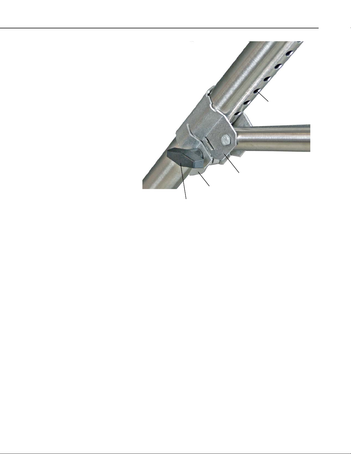
Secure the mast in the upright position by installing the locking bracket (Figure
5-4A). Insert the top of the bracket into the notches in the tripod base, and
using both thumbs, press the bracket into the body of the base until the lower
tabs lock into position. Install the pin as shown in Figure 5-4C. To remove the
bracket, remove the pin and squeeze the lower part of the bracket to disengage
the tabs, then rotate the bracket out and up.
Plumb the tripod by adjusting the northeast and south facing legs. With a level
on the East side of the mast, adjust the Northeast leg for plumb. With the level
on the South side of the mast, adjust the South leg for plumb.
7
Page 12

Tripod Installation Manual Models CM110, CM115, CM120
t
Locking Bracke
Lower Tabs
8
Pin
FIGURE 5-4. Mast Lock Bracket
Page 13

Tripod Installation Manual Models CM110, CM115, CM120
5.3 Installing the Guy Kit
The CM115 and CM120 tripods include a guy kit; the guy kit is an option for
the CM110. With the mast tilted down in the horizontal position, install the
guy collar over the mast insert, and attach the guy wires as shown in Figure
5-5. Return the mast to the upright position and install the locking bracket.
Guy Collar
Guy Wire
FIGURE 5-5. Guy Collar
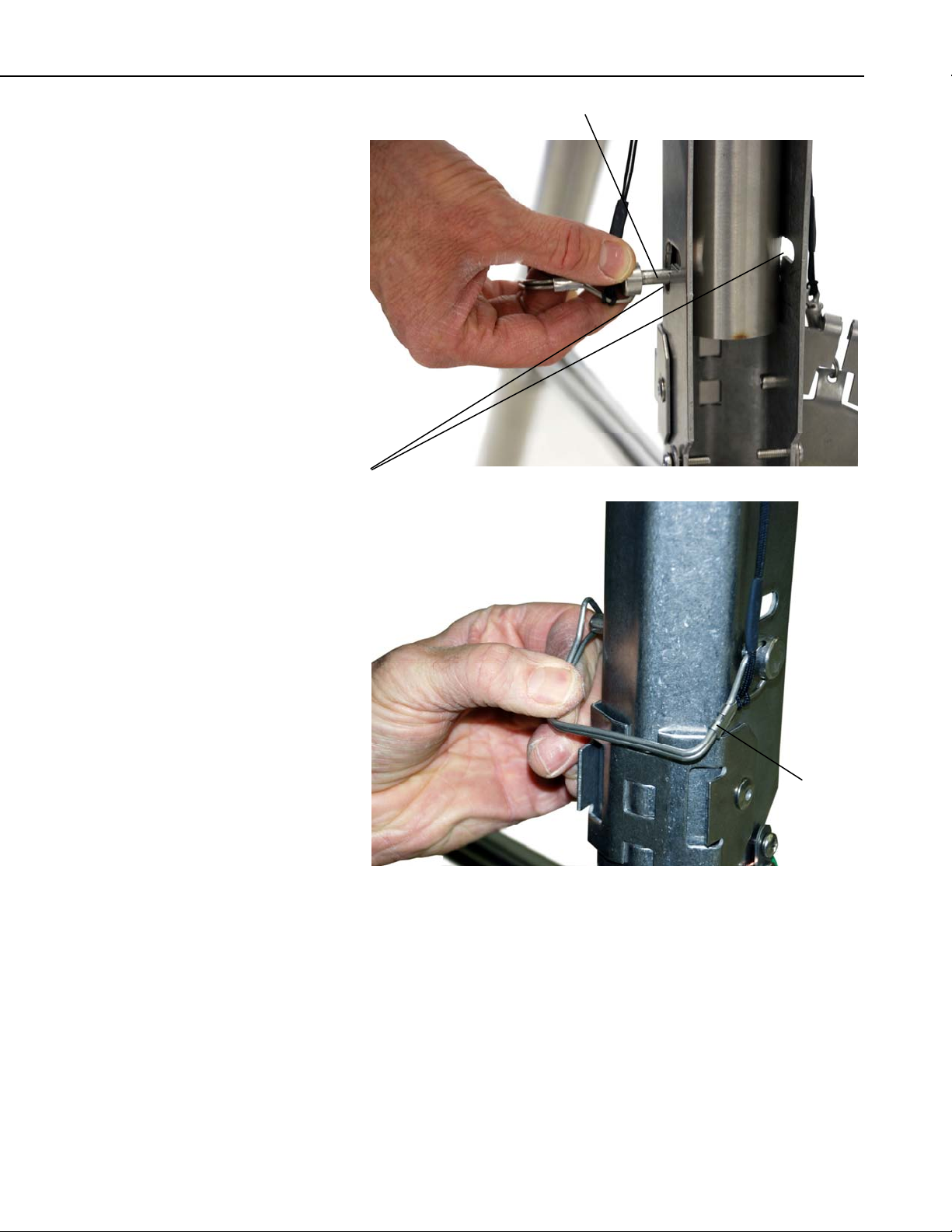
On the end of each guy line is a case consisting of a hook, clamp, and lever
arm. Rotate the lever arm to the “open” position, and attach the hook to the
tripod leg as shown in Figure 5-6. Loosen the Phillips screw, and remove the
slack in the guy line by feeding the load end of the guy wire through the wedge
while pulling up on the dead end (Figure 5-7).
After the slack has been removed from the guy lines, tighten the Phillips
screws and rotate the lever arms to “closed” position to tension the guy lines.
9
Page 14

Tripod Installation Manual Models CM110, CM115, CM120
Phillips Screw
Lever Arm “Open”
Hook
Lever Arm “Closed”
FIGURE 5-6. Guy Cinch and Lever Arm
10
Page 15

Tripod Installation Manual Models CM110, CM115, CM120
load end
dead end
Phillips screw
lever
hook
FIGURE 5-7. Mechanical Drawing of Guy Hook and Case
5.3.1 Guy Duckbill Anchor Kits
Duckbill anchors are recommended for areas subjected to higher winds. They
allow the guy wires to be anchored at points beyond the feet, thereby
increasing the rating of the tripod for higher winds.
Two duckbill anchor kits are offered for these lightweight tripods. The 19282
Guy Duckbill Standard Anchor Kit is for standard soils, and the 25699 Guy
Duckbill Heavy Duty Kit is for aggressive soils. Aggressive soils have:
• Resistivity of less than 3000 ohm-cm
• pH of less than 5
• Chloride of greater than 1000 ppm
• Sulfate of greater than 500 ppm
• Poor aeration
The 19282 and 25699 have their own drive bar. The 19282 also has thr ee
duckbill anchors with a cable attached to each of them. At the end of the cable
is a loop for connecting the guy wires. The 25699 has a threaded rod attached
to each of the three duckbill anchors instead of the cable. At the end of the
threaded rod is a metal ring for connecting the guy wires.
The duckbill anchors are driven to the ground at a 60-degree guy angle as
shown in Figure 5-8. Locate the anchors on a 7.5’ radius for the CM115, or a
10’ radius for the CM120 as shown in Figure 5-9. Specifications for sustained
wind speed and gust tolerance are given based on guy angle, and the ability of
the anchors to hold at least 400 lbf.
NOTE
Dukbill anchors are not suitable for rocky or sandy soils; the
UTEYE anchors should be considered for these types of soils.
11
Page 16

Tripod Installation Manual Models CM110, CM115, CM120
r
r
It is important that the anchors be driven at the same angle as the guy wires.
Insert the drive bar into the anchor body and drive the anchor into the ground
using a sledgehammer until only the top half of the loop or metal ring remains
above the ground. Place a bar or highlift jack through the loop or metal ring
and jack the anchor up about four inches to rotate the an chor into the load-lock
position.
WARNING
Failure to install and lock the anchor at the correct
angle will result in the anchor cable cutting through
the soil until the angles equalize, causing slack
Drive Ba
Duckbill Ancho
o
60
FIGURE 5-8. Duckbill Guy Anchor
12
Page 17

Tripod Installation Manual Models CM110, CM115, CM120
RADIUS
Distance between anchors
120
CENTER POINT
TILT DIRECTION
(NORTH)
ANCHOR LOCATIONS
(3) PLCS
Radius Distance Between Anchors
CM115 7.5’ 13’
CM120 10’ 17.3’
FIGURE 5-9. Top View and Guy Anchor Layout
5.3.2 Lowering Mast after Attaching Guy Wires
Once the guy lines have been adjusted the lever arms can be “opened” and the
guy hooks removed to allow the mast to be lowered to the horizontal position.
13
Page 18

Tripod Installation Manual Models CM110, CM115, CM120
5.4 Staking the Tripod Feet
Six stakes are provided for securing the tripod feet to the ground. Drive two
stakes through holes in each foot at an angle as shown in Figure 5-10.
Stakes may not be adequate depending on soil structure, maximum wind
speeds experienced at the site, mast height, or wind load from the
instrumentation. For questionable situations, additional stakes (PN 17049) or
even concrete footings for the tripod feet and guy anchors should be
considered.
FIGURE 5-10. Staking the Tripod Feet
14
Page 19

5.5 Tripod Grounding
Place the clamp over the ground rod and drive the rod (close to the center of
the tripod) using a sledge hammer or fence post driver. Strip 1/2” inch of
insulation from both ends of the black 4 AWG ground wire. Insert one end of
the ground wire between the clamp and ground rod and tighten the bolt on the
clamp. Attach the other end of the ground wire to the lug on the tripod base as
shown in Figure 5-12.
Tripod Installation Manual Models CM110, CM115, CM120
FIGURE 5-11. Ground Rod and Clamp
Strip 1/2” of insulation from the ends of the green 12 AWG wire. Attach one
end of the wire to the tripod ground lug, and the other end to the enclosu re
ground lug as shown in Figure 5-12.
Mount the lightning rod and clamp to the tripod mast as shown in Figure 5-12.
15
Page 20

Tripod Installation Manual Models CM110, CM115, CM120
Lightning Rod
Clamp
Ground Lug
Ground Wire
Enclosure Ground Lug
16
Enclosure Ground Wire
Ground Lug
FIGURE 5-12. Lightning Rod and Tripod Grounding Lug
Page 21

Tripod Installation Manual Models CM110, CM115, CM120
5.6 Crossarm Attachment
Attach the CM202 (2 ft, 0.6m), CM204 (4 ft, 1.2m), or CM206 (6 ft, 1.8m)
crossarm to the tripod mast as shown in Figure 5-13. For wind sensors, the
crossarm should be approximately 103 inches above the ground for a 3m
mounting height, or 64 inches for a 2m mounting height. Typically the
crossarm is oriented East/West for wind sensors, North/South for
pyranometers.
FIGURE 5-13. CM204 Crossarm
5.7 Enclosure Attachment
The ENC 10/12, ENC 12/14, ENC 14/16, and ENC 16/18 enclosures can be
ordered with mounting brackets for the CM100 series tripods. All enclosure
models can be mounted to the tripod mast (above the legs) with the –MM Mast
Mount bracket option. All enclosure models except the ENC 16/18 can be
mounted to the tripod base and leg with the –LM Leg Mount bracket option.
Two enclosures with the –LM brackets can be mounted in a “back to back”
configuration.
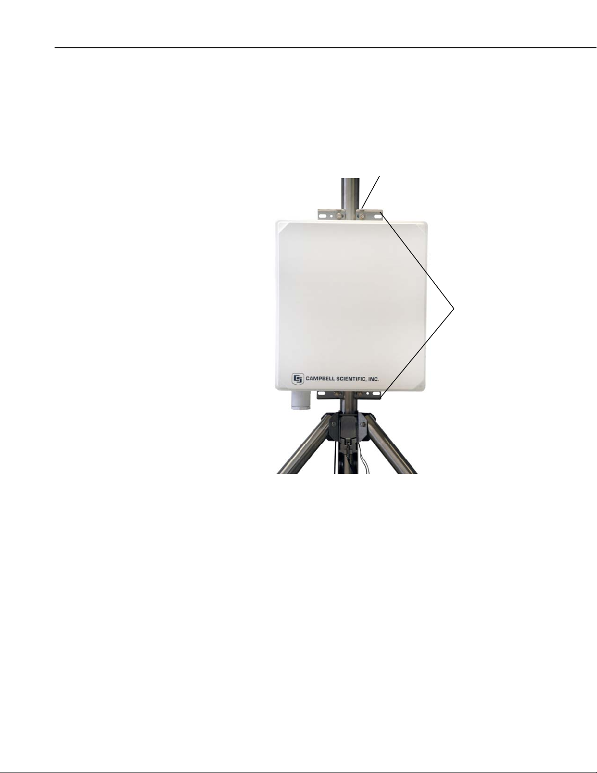
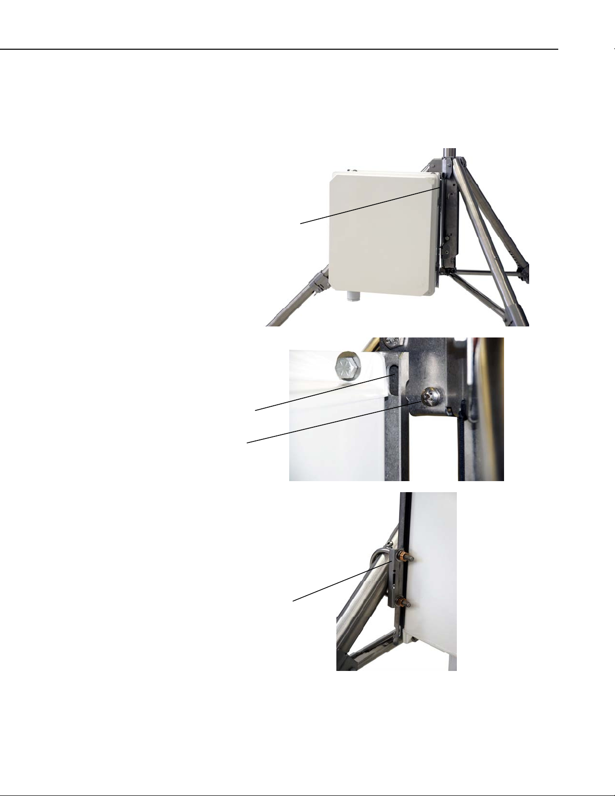
5.7.1 Enclosure Mounting to Tripod Mast
An enclosure ordered with the –MM bracket has a three-piece top and bottom
brackets with a U-bolt for each bracket.
Attach an enclosure with the –MM mounting bracket to the tripod mast as
follows:
CM200 Series
Crossarm
Tripod Mast
Remove the U-bolts washers and nuts from the brackets.
Position the enclosure against the tripod’s mast (North side recommended).
17
Page 22
Tripod Installation Manual Models CM110, CM115, CM120
–
Install the U-bolts, flat washers, lock washers, and nuts. Tighten the nuts until
the lock washers are compressed.
Route the 14 AWG wire from the grounding lug on the bottom side of the
enclosure to the grounding lug on the base of the tripod (Figure 5-14). Strip
1/2” of insulation from each end of the wire. Insert wire ends into the
grounding lugs and tighten.
U-Bolt
MM Bracket
18
FIGURE 5-14. Enclosure with the –MM Bracket
5.7.2 Enclosure Mounting to Tripod Leg
An enclosure ordered with the –LM bracket has a bracket on each side of the
enclosure, and a U-bolt bracket for securing the enclosure to a tripod leg.
Attach an enclosure with the –LM mounting bracket to the tripod base as
follows:
Slide the keyhole notches in the upper and lower corners of the –LM bracket
over the two extended Phillips head screws located on the tripod base as shown
in Figure 5-15B.
Remove the washers, nuts and U-bolt from the U-bolt bracket. Install the
bracket as shown in Figure 5-15C. Tighten the nuts on the U-bolt until the lock
washers are compressed.
Page 23
Tripod Installation Manual Models CM110, CM115, CM120
t
Route the 14 AWG wire from the grounding lug on the bottom side of the
enclosure to the grounding lug on the base of the tripod (Figure 5-15). Strip
1/2” of insulation from each end of the wire. Insert wire ends into the
grounding lugs and tighten.
–LM Bracket
Keyhole Notch
Phillips Head Screw
U-Bolt Bracke
FIGURE 5-15. Enclosure with the –LM Bracket
19
Page 24

Tripod Installation Manual Models CM110, CM115, CM120
6. Mounting Brackets
Mounting brackets covered in this section have U-bolts that attach to vertical
and/or horizontal pipes with the following ranges of outside diameters:
inches mm Nominal Pipe Size (inches)
1.5” U-bolt 1.0 – 1.5 25.4 – 38.1 ¾ – 1
2” U-bolt 1.3 – 2.1 33.0 – 53.3 1 – 1 ½
2” U-bolt
with plastic V-block
Some of the brackets (e.g. the CM210) include 1.5” and 2” U-bolts to extend
the range of pipe diameters that the bracket can accommodate. Brackets with
holes for a 1.5” U-bolt will accept a user-supplied 1.75” U-bolt.
1.0 – 2.1 25.4 – 53.3 ¾ – 1 ½
6.1 CM210 Crossarm Mounting Kit
CM200 series crossarms include a CM210 bracket as shown in Figure 6-1.
The CM210 can be ordered separately to attach a user-supplied pipe (1.0 –
1.5” OD) to a mast or tower leg (1.0 – 2.1” OD), or to attach a crossarm to two
tower legs.
CM210
20
FIGURE 6-1. CM210 Crossarm Mounting Kit
(shown with user-supplied pipe)
Page 25
Tripod Installation Manual Models CM110, CM115, CM120
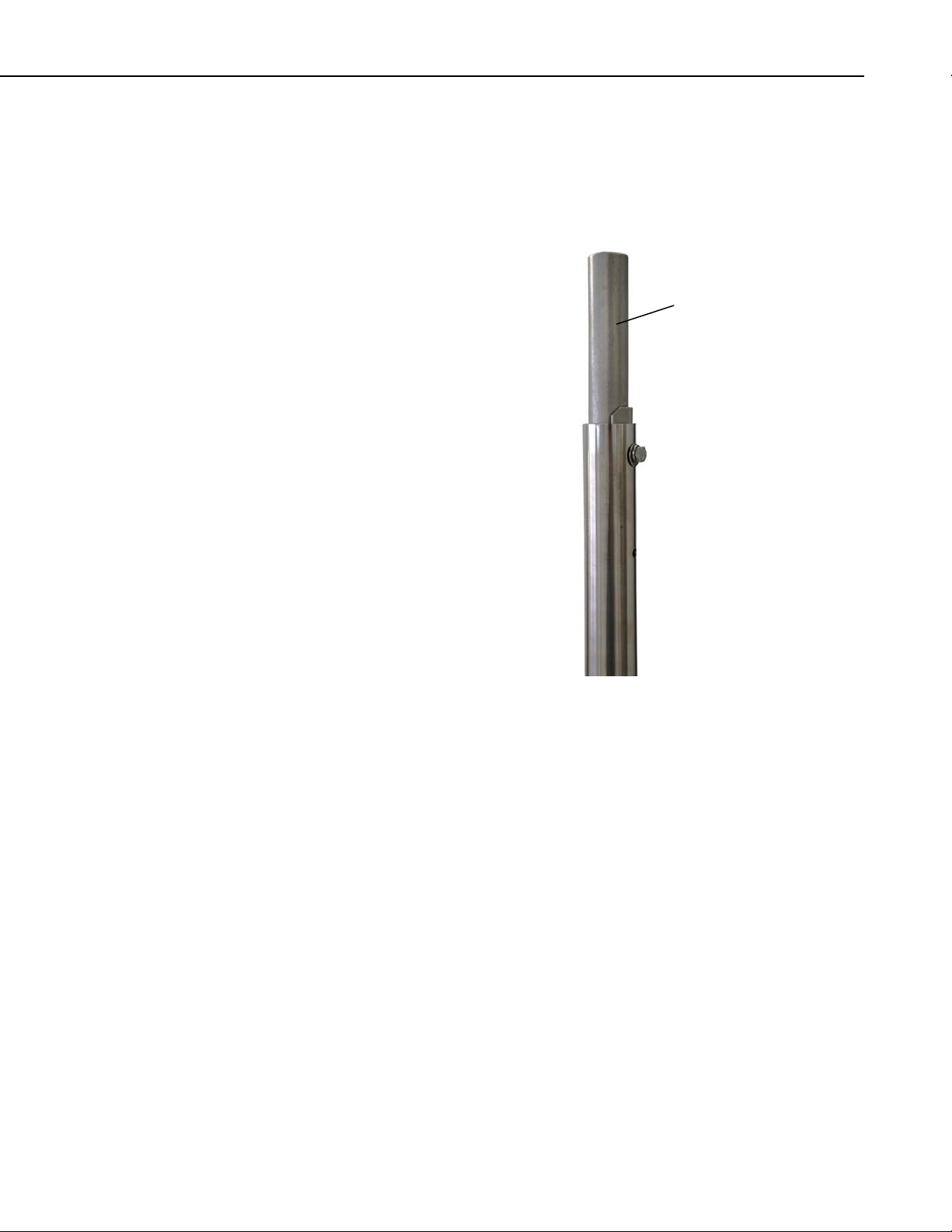
6.2 CM216 Mast Mounting Kit
The CM216 attaches to the top of the mast, and provides a 3/4” or 1” mounting
pipe (1.05” or 1.32” OD) that extends 4” above the mast, as shown in Figure
6-2.
CM216
FIGURE 6-2. CM216 Mast Mounting Kit
21
Page 26

Tripod Installation Manual Models CM110, CM115, CM120
6.3 CM220 Right Angle Mounting Kit
The CM220 attaches a vertical pipe (1.0 – 1.5” OD) to the CM200 series
crossarms or horizontal pipe (1.0 – 1.5” OD ) as show n in Fi gu re 6- 3.
CM220
CM220
22
FIGURE 6-3. CM220 Right Angle Mounting Kit
Page 27

Tripod Installation Manual Models CM110, CM115, CM120
6.4 CM225 and 18098 Pyranometer Mounting Stand
The CM225 is used to attach a pyranometer or quantum sensor to a horizontal
pipe (1.0 to 2.1” OD) or vertical pole (1.0 to 2.1” OD).
The LI200X pyranometer and LI190SB quantum sensor mount to the CM225
via the LI200S leveling base (see Figure 6-4). The CS300 pyranometer mounts
to the CM225 via the 18356 leveling base. The CMP3 and LP02 pyranometers
include their own bubble level and leveling screws allowing them to mount
directly to the CM225.
The 18098 provides a larger surface for mounting a user-supplied Eppley
pyranometer.
LI2003S
CM225
LI200X Pyranometer
CM225
FIGURE 6-4. CM225 Pyranometer Mounting Stand
23
Page 28

Tripod Installation Manual Models CM110, CM115, CM120
6.5 CM230 Adjustable Angle Mounting Kit
The CM230 mounts an antenna (1.0 – 1.5” OD) to a mast or vertical pipe
(1.3 – 2.1” OD) as shown in Figure 6-5. The bracket allows the antenna to be
adjusted for different angles.
CM230
FIGURE 6-5. CM230 Adjustable Angle Mounting Kit
24
Page 29

Tripod Installation Manual Models CM110, CM115, CM120
6.6 CM235 Magnetic Mounting Stand
The CM235 provides a 3.5” (8.8 cm) square platform for mounting magnetic
base antennas. The CM235 attaches to horizontal or vertical pi pes (1. 0 –
2.1” OD) as shown in Figure 6-6.
FIGURE 6-6. CM235 Magnetic Mounting Stand
25
Page 30

Tripod Installation Manual Models CM110, CM115, CM120
6.7 RM Young Gill Radiation Shields
RM Young Gill Radiation Shields are used to house and attach temperature and
relative humidity sensors to the tripod mast (1.0 – 2.1” OD) or crossarm as
shown in Figure 6-7. Radiation shields ship with the U-bolt configured for
attachment to a vertical pipe. To attach the radiation shield to a horizontal
pipe, the U-bolt and plastic V-block must be moved to the other set of holes.
26
FIGURE 6-7. RM Young Gill Radiation Shield
Page 31

Appendix A. Tripod Tote Bag
The Tripod Tote Bag is an option for the CM110 series tripods. The bag is
constructed of nylon, with a main compartment for the tripod base, and pocke ts
for stowing the other components as shown below:
Guy Kit
Mast(s)
Ground Rod
Lightning Rod
Tripod Base
(6) Stakes
Ground Wires
A-1
Page 32

Page 33

Page 34

Campbell Scientific Companies
Campbell Scientific, Inc. (CSI)
815 West 1800 North
Logan, Utah 84321
UNITED STATES
www.campbellsci.com • info@campbellsci.com
Campbell Scientific Africa Pty. Ltd. (CSAf)
PO Box 2450
Somerset West 7129
SOUTH AFRICA
www.csafrica.co.za • cleroux@csafrica.co.za
Campbell Scientific Australia Pty. Ltd. (CSA)
PO Box 444
Thuringowa Central
QLD 4812 AUSTRALIA
www.campbellsci.com.au • info@campbellsci.com.au
Campbell Scientific do Brazil Ltda. (CSB)
Rua Luisa Crapsi Orsi, 15 Butantã
CEP: 005543-000 São Paulo SP BRAZIL
www.campbellsci.com.br • suporte@campbellsci.com.br
Campbell Scientific Canada Corp. (CSC)
11564 - 149th Street NW
Edmonton, Alberta T5M 1W7
CANADA
www.campbellsci.ca • dataloggers@campbellsci.ca
Campbell Scientific Centro Caribe S.A. (CSCC)
300 N Cementerio, Edificio Breller
Santo Domingo, Heredia 40305
COSTA RICA
www.campbellsci.cc • info@campbellsci.cc
Campbell Scientific Ltd. (CSL)
Campbell Park
80 Hathern Road
Shepshed, Loughborough LE12 9GX
UNITED KINGDOM
www.campbellsci.co.uk • sales@campbellsci.co.uk
Campbell Scientific Ltd. (France)
Miniparc du Verger - Bat. H
1, rue de Terre Neuve - Les Ulis
91967 COURTABOEUF CEDEX
FRANCE
www.campbellsci.fr • info@campbellsci.fr
Campbell Scientific Spain, S. L.
Avda. Pompeu Fabra 7-9, local 1
08024 Barcelona
SPAIN
www.campbellsci.es • info@campbellsci.es
Please visit www.campbellsci.com to obtain contact information for your local US or International representative.
 Loading...