

Page 1

INSTRUCTION MANUAL
CCFC Field Camera
May 2016
Copyright © 2016
Campbell Scientific (Canada) Corp.
Page 2

Page 3

Guarantee
This equipment is guaranteed against defects in materials and workmanship.
We will repair or replace products which prove to be defective during the
guarantee period as detailed on your invoice, provided they are returned to us
prepaid. The guarantee will not apply to:
Equipment which has been modified or altered in any way without the
written permission of Campbell Scientific
Batteries
Any product which has been subjected to misuse, neglect, acts of God or
damage in transit.
Campbell Scientific will return guaranteed equipment by surface carrier
prepaid. Campbell Scientific will not reimburse the claimant for costs incurred
in removing and/or reinstalling equipment. This guarantee and the Company’s
obligation thereunder is in lieu of all other guarantees, expressed or implied,
including those of suitability and fitness for a particular purpose. Campbell
Scientific is not liable for consequential damage.
Please inform us before returning equipment and obtain a Repair Reference
Number whether the repair is under guarantee or not. Please state the faults as
clearly as possible, and if the product is out of the guarantee period it should
be accompanied by a purchase order. Quotations for repairs can be given on
request. It is the policy of Campbell Scientific to protect the health of its
employees and provide a safe working environment, in support of this policy a
“Declaration of Hazardous Material and Decontamination” form will be
issued for completion.
When returning equipment, the Repair Reference Number must be clearly
marked on the outside of the package. Complete the “Declaration of
Hazardous Material and Decontamination” form and ensure a completed copy
is returned with your goods. Please note your Repair may not be processed if
you do not include a copy of this form and Campbell Scientific Ltd reserves
the right to return goods at the customers’ expense.
Note that goods sent air freight are subject to Customs clearance fees which
Campbell Scientific will charge to customers. In many cases, these charges are
greater than the cost of the repair.
Campbell Scientific Ltd,
80 Hathern Road,
Shepshed, Loughborough, LE12 9GX, UK
Tel: +44 (0) 1509 601141
Fax: +44 (0) 1509 601091
Email: support@campbellsci.co.uk
www.campbellsci.co.uk
Page 4

Page 5

Precautions
DANGER — MANY HAZARDS ARE ASSOCIATED WITH INSTALLING, USING, MAINTAI NING, AND WORKING ON
OR AROUND TRIPODS, TOWERS, AND ANY ATTACHMENTS TO TRIPODS AND TOWERS SUCH AS SENSORS,
CROSSARMS, ENCLOSURES, ANTENNAS, ETC. FAILURE TO PROPERLY AND COM P LE TE LY ASS E M BLE ,
INSTALL, OPERATE, USE, AND MAINTAIN TRIPODS, TOWERS, AND ATTACHMENTS, AND FAILURE TO HEED
WARNINGS, INCREASES THE RISK OF DEATH, ACCIDENT, SERIOUS INJURY, PROPERTY DAMAGE, AND
PRODUCT FAILURE. TAKE ALL REASONABLE PRECAUTIONS TO AVOID THESE HAZARDS. CHECK WITH YOUR
ORGANIZATION'S SAFETY COORDINATOR (OR POLICY) FOR PROCEDURES AND REQUIRED PROTECTIVE
EQUIPMENT PRIOR TO PERFORMING ANY WORK.
Use tripods, towers, and attachments to tripods and towers only for purposes for which they are designed. Do not
exceed design limits. Be familiar and comply with all instructions provided in product manuals. Manuals are
available at www.campbellsci.eu or by telephoning +44(0) 1509 828 888 (UK). You are responsible for conformance
with governing codes and regulations, including safety regula tions, and the integrity and location of structures or l and
to which towers, tripods, and any attachments are attached. Installation sites should be evaluated and approved by a
qualified engineer. If questions or co ncerns arise regarding installation, use, or maintenance of tripods, towers,
attachments, or electrical connections, consult with a licensed and qualified engineer or electrician.
General
• Prior to performing site or installation work, obtain required approvals and permits. Comply with all
governing structure-height regulations, such as those of the FAA in the USA.
• Use only qualified personnel for installation, use, and maintenance of tripods and towers, and any
attachments to tripods and towers. The use of licensed and qualified contractors is highly recommended.
• Read all applicable instructions carefully and understand procedures thoroughly before beginning work.
• Wear a hardhat and eye protection, and take other appropriate safety precautions while working on or
around tripods and towers.
• Do not climb tripods or towers at any time, and prohibit climbing by other persons. Take reasonable
precautions to secure tripod and tower sites from trespassers.
• Use only manufacturer recommended parts, materials, and tools.
Utility and Electrical
• You can be killed or sustain serious bodily injury if the tripod, tower, or attachments you are installing,
constructing, using, or maintaining, or a tool, stake, or anchor, come in contact with overhead or
underground utility lines.
• Maintain a distance of at least one-and-one-half times structure height, or 20 feet, or the distance
required by applicable law, whichever is greater, between overhead utility lines and the structure (tripod,
tower, attachments, or tools).
• Prior to performing site or installation work, inform all utility companies and have all underground utilities
marked.
• Comply with all electrical codes. Electrical equipment and related grounding devices should be installed
by a licensed and qualified electrician.
Elevated Work and Weather
• Exercise extreme caution when performing elevated work.
• Use appropriate equipment and safety practices.
• During installation and maintenance, keep tower and tripod sites clear of un-trained or non-essential
personnel. Take precautions to prevent elevated tools and objects from dropping.
• Do not perform any work in inclement weather, including wind, rain, snow, lightning, etc.
Maintenance
• Periodically (at least yearly) check for wear and damage, including corrosion, stress cracks, frayed cables,
loose cable clamps, cable tightness, etc. and take necessary corrective actions.
• Periodically (at least yearly) check electrical ground connections.
WHILE EVERY ATTEMPT IS MADE TO EMBODY THE HIGHEST DEGREE OF SAFETY IN ALL CAMPBELL
SCIENTIFIC PRODUCTS, THE CUSTOMER ASSUMES ALL RISK FROM ANY INJURY RESULTING FROM IMPROPER
INSTALLATION, USE, OR MAINTENANCE OF TRIPODS, TOWERS, OR ATTACHMENTS TO TRIPODS AND TOWERS
SUCH AS SENSORS, CROSSARMS, ENCLOSURES, ANTENNAS, ETC.
Page 6

Page 7

IR Warning
IR LEDs
Infrared (IR) is emitted from the CCFC. Do not look directly at the
IR LED when the CCFC is connected to power.
The CCFC utilizes 2 high intensity nonvisible IR (850 nm) LEDs
for night vision illumination.
Do not make physical contact with the IR LEDs or place any body
part near the IR LEDs (less than 5cm) while the camera is powered
on. When in close proximity with the illuminated IR LEDs, there is
a potential skin burn hazard.
See Section 5 Cautionary Statements for more information.
Page 8

Page 9

Table of Contents
PDF viewers: These page numbers refer to the printed version of this document. Use
the PDF reader bookmarks tab for links to specific sections.
1. Introduction .................................................................. 1
2. Specifications .............................................................. 2
3. Initial Inspection .......................................................... 4
4. Quick Notes .................................................................. 4
4.1 CCFC General ................................................................. 4
4.2 Campbell Dataloggers Users ........................................... 5
4.3 Configuration Process ..................................................... 6
5. Cautionary Statements ............................................... 8
6. Factory Setup ............................................................... 9
7. Camera Hardware ...................................................... 10
7.1 Power I/O Connection ................................................... 10
7.2 Setup Button/Status LED............................................... 11
7.2.1 Status LED .............................................................. 11
7.2.2 Setup Button ............................................................ 12
7.3 Camera Memory ........................................................... 13
7.3.1 Link to Most Recent Photo and Video ..................... 13
7.3.2 FTP Photo Collection from Camera Memory ........... 14
7.4 Modem Power Control .................................................. 15
7.5 Lens .............................................................................. 15
7.5.1 Camera Lens and Field of View ............................... 16
7.5.2 Camera Auto Focus ................................................. 16
7.5.3 Temperature Variations and Focus........................... 16
7.5.4 Lens IR Cut Filter .................................................... 17
8. Cables/Wiring ............................................................. 17
8.1 Power & I/O Cable Connections .................................... 17
8.2 Power & I/O Cable Details ............................................ 19
8.3 Ethernet Cables ............................................................. 19
9. Using Device Configuration Utility .......................... 20
10. Photo Quality ............................................................. 22
11. Connecting to the Web Interface ............................. 22
11.1 Setup Using Wi-Fi......................................................... 23
11.2 Setup Using Ethernet ..................................................... 23
i
Page 10

Table of Contents
12. Camera Operation using the Web Interface ............ 24
11.2.1 Link Local IP Address Auto-Configuration ..............23
12.1 Installing MultiMedia Player..........................................24
12.1.1 RTSP Video Stream .................................................24
12.1.1.1 Sources ............................................................24
12.1.1.2 Embedding ......................................................25
12.1.2 UPnP Discovery .......................................................25
12.2 Web Interface Overview ................................................25
12.2.1 Live Video Modal ....................................................29
12.2.2 Power Icon ...............................................................29
12.2.3 Set Up Progress Bar .................................................30
12.3 Dashboard .....................................................................30
12.4 Capture Modes...............................................................32
12.4.1 Timed Capture ................................ .........................33
12.4.2 External Trigger .......................................................38
12.4.3 Motion Detect ..........................................................43
12.5 Lens Position .................................................................49
12.6 Media Settings ...............................................................51
12.6.1 Photo Capture ..........................................................52
12.6.2 Video Capture ..........................................................55
12.7 File Explorer ..................................................................58
12.8 Settings ..........................................................................59
12.8.1 General ................................................................ ....59
12.8.1.1 SNTP ..............................................................61
12.8.2 Network ...................................................................62
12.8.2.1 Wired Ethernet Settings ...................................63
12.8.2.2 Wi-Fi Settings .................................................64
12.8.2.3 Wi-Fi Access Mode .........................................65
12.8.2.3.1 Wi-Fi Access Point .................................65
12.8.2.3.2 Existing Network ....................................67
12.8.3 File Transfer ............................................................68
12.8.3.1 FTP .................................................................69
12.8.3.2 Email ...............................................................70
12.8.3.3 PakBus ................................ ............................72
12.8.4 Camera Operation ....................................................74
12.8.4.1 Camera Power Modes ......................................74
12.8.4.2 Ethernet Power Mode ................................ ......77
12.8.4.3 Wi-Fi Power Mode ..........................................78
12.8.4.4 Night Mode .....................................................79
12.8.4.4.1 IR LED Power Control ...........................80
12.8.4.4.2 Filter Control ..........................................81
12.8.4.4.3 Light Power Control ...............................81
12.8.4.5 Digital I/O .......................................................81
12.8.4.5.1 Modem Power Control ............................82
12.8.4.5.2 Lens Defroster Control ...........................83
12.8.5 Advanced .................................................................84
12.8.5.1 GPS ................................ .................................84
12.8.5.2 Import/Export ..................................................85
12.8.5.3 Update .............................................................86
ii
Page 11

12.8.5.4 Users............................................................... 88
12.8.5.5 History ............................................................ 89
13. RS-232 Communications .......................................... 90
14. RS-485 Communications .......................................... 92
15. Send Via PakBus: PakBus Communications ......... 92
15.1 Send Via PakBus: Concurrent PakBus Communications 93
15.2 Send Via PakBus: PakBus Graph Operations................. 93
15.2.1 Dataogger Settings .................................................. 93
15.2.2 Discovery ................................................................ 93
15.3 Setting Up Datalogger to Work with CCFC: PakBus
Variable Control ......................................................... 94
15.3.1 PakBus Control of Window Defroster Function ....... 95
15.3.2 PakBus Control of CCFC Power .............................. 95
15.3.3 Example Program – SendVariable Instruction –
DATALOGGER ................................................... 95
15.3.4 Example Program – Adding GPS Coordinates to the
Photo Banner – DATALOGGER .......................... 96
15.4 PakBus Neighbouring Address ...................................... 97
16. Power Calculations and Timings ............................. 97
16.1 Standalone Operation .................................................... 97
16.2 Operation with Communications ................................ ... 99
17. CCFC Compatability ................................................ 101
18. DATALOGGER Interface Guide.............................. 101
18.1 DATALOGGER Memory Setup ................................. 101
18.2 DATALOGGER Files Manager .................................. 102
18.3 DATALOGGER COM Port (Control Port)
Communications....................................................... 103
19. Remote Photo Retrieval .......................................... 103
19.1 LoggerNet File Retrieval ............................................. 104
19.2 Using LoggerNet File Control ..................................... 105
20. Mounting ................................................................... 107
21. Maintenance ............................................................. 108
21.1 Lithium Battery ........................................................... 108
21.2 Window and Lens Cleaning......................................... 109
22. System Limitations .................................................. 109
22.1 High Resolution 5 Megapixel Photos........................... 109
22.2 Simultaneous Processes ............................................... 109
Page 12

Table of Contents
Appendix A. CCFC Camera Accessories .................. A-1
Figures
A.1 CCFCCBL1-L Power & I/O Cable.............................. A-1
A.2 CCFCCBL2-L Environmental Ethernet Cable............. A-2
A.3 L18549 Mounting Kit ................................................. A-2
A.4 L28840 DB9 FEMALE To Terminal Block Adaptor ... A-3
Figure 1-1 CCFC Camera ......................................................... 1
Figure 7-1 CCFC Connector Layout ........................................10
Figure 7-2 Photo Collection from Installed Camera Memory ...15
Figure 9-1 CCFC shown in Device Configuration Utility ........22
Figure 12-1 Dashboard - Desktop view ...................................26
Figure 12-2 Dashboard - Mobile views ...................................26
Figure 12-3 Top Navigation Bar – Desktop view .....................29
Figure 12-4 Live Video Modal .................................................29
Figure 12-5 Set Up Progress bar ..............................................30
Figure 12-6 CCFC Dashboard.................................................30
Figure 12-7 Manual Capture Modal .........................................32
Figure 12-8 Timed Capture .....................................................33
Figure 12-9 Timed Capture: Create New Profile .....................34
Figure 12-10 External Trigger .................................................39
Figure 12-11 External Trigger: Create New Profile .................40
Figure 12-12 Motion Detect.....................................................43
Figure 12-13 Motion Detect: Create New Profile .....................45
Figure 12-14 Lens Position ......................................................49
Figure 12-15 Lens Position Modal ...........................................49
Figure 12-16 Lens Position Modal (in Capture Modes) ............49
Figure 12-17 Media Settings ....................................................51
Figure 12-18 Media Settings: Edit Photo Profile ......................52
Figure 12-19 Photo Settings Modal .........................................52
Figure 12-20 Media Settings: Edit Video Profile .....................56
Figure 12-21 Video Settings Modal..........................................56
Figure 12-22 File Explorer: Camera Memory Details ..............58
Figure 12-23 File Explorer: File Details ..................................59
Figure 12-24 General Settings .................................................60
Figure 12-25 Date and Time Settings: Sync with SNTP Server 61
Figure 12-26 Network ..............................................................62
Figure 12-27 Network Pop-up on Google Chrome ...................62
Figure 12-28 Wired Ethernet Settings ......................................63
Figure 12-29 Wi-Fi Settings.....................................................64
Figure 12-30 Access Point Settings ..........................................65
Figure 12-31 Connect to Existing Network ..............................67
Figure 12-32 FTP Settings .......................................................69
Figure 12-33 FTP Settings Modal ............................................69
Figure 12-34 Email Settings ....................................................71
Figure 12-35 Email Settings Modal .........................................71
Figure 12-36 PakBus Settings ..................................................72
Figure 12-37 PakBus Modal ....................................................73
Figure 12-38 Camera Power Modes ........................................74
iv
Page 13

Figure 12-39 Ethernet Power Modes ....................................... 77
Figure 12-40 Wi-Fi Power Mode ............................................ 78
Figure 12-41 Night Mode ........................................................ 80
Figure 12-42 Digital I/O Settings ............................................ 82
Figure 12-43 Modem Power Control ....................................... 82
Figure 12-44 Lens Defroster Control: Always On ................... 83
Figure 12-45 Lens Defroster Control: Prior to Capture .......... 83
Figure 12-46 GPS ................................................................... 84
Figure 12-47 GPS: Degrees, Minutes, Seconds ....................... 84
Figure 12-48 GPS: Decimal Degrees ...................................... 85
Figure 12-49 Import/Export Camera Settings .......................... 85
Figure 12-50: Update .............................................................. 87
Figure 12-51 Users and Security Settings ................................ 88
Figure 12-52 History ............................................................... 90
Figure 13-1 PakBus Settings ................................................... 90
Figure 13-2 L28840 DB9 FEMALE to Terminal Block
Adapter ...................................................................... 91
Figure 19-1 File Retrieval Setup Screen ................................ 104
Figure 19-2 Loggernet Connection Screen ............................ 106
Figure 19-3 USR Drive View in File Control ........................ 106
Figure 20-1 CCFC Mounting Kit .......................................... 107
Figure 20-2 CCFC Mounting Holes ...................................... 107
Figure 20-3 CCFC Mounted to Crossarm .............................. 108
Tables
TABLE 4-1 Power Mode Summary* ........................................ 7
TABLE 6-1 CCFC Factory Default Configuration .................... 9
TABLE 7-1 Setup Button Status LED ..................................... 12
TABLE 8-1 Power & I/O Cable Connections .......................... 18
TABLE 9-1 RS-232 Wiring Diagram ...................................... 21
TABLE 12-1 Video Stream Sources ....................................... 25
TABLE 12-2 Web Interface Components ............................... 27
TABLE 12-3 Dashboard Components ..................................... 31
TABLE 12-4 Timed Capture Variables for Photos .................. 35
TABLE 12-5 Timed Capture Variables for Videos.................. 37
TABLE 12-6 External Trigger Variables for Photos ................ 40
TABLE 12-7 External Trigger Variables for Video ................. 42
TABLE 12-8 Motion Detect Settings for Photo Options.......... 45
TABLE 12-9 Motion Detect Settings for Video Options ......... 47
TABLE 12-10 Lens Positions Modal ...................................... 50
TABLE 12-11 Minimum Focal Length ................................... 51
TABLE 12-12 Photo Capture Variables .................................. 53
TABLE 12-13 Photo Resolution Details ................................. 54
TABLE 12-14 Video Capture Variables.................................. 57
TABLE 12-15 Typical Video File Sizes .................................. 58
TABLE 12-16 General Settings Variables............................... 60
TABLE 12-17 Wired Ethernet Settings ................................... 63
TABLE 12-18 Wi-Fi Settings ................................................. 65
Page 14

Table of Contents
TABLE 12-19 Access Point Settings .......................................66
TABLE 12-20 Existing Network Settings for Wi-Fi Clients ....68
TABLE 12-21 FTP Settings ....................................................70
TABLE 12-22 Email Settings ..................................................71
TABLE 12-23 PakBus Settings ...............................................74
TABLE 12-24 Camera Power Modes ......................................75
TABLE 12-25 Capture Response Time ...................................77
TABLE 12-26 Ethernet Power Modes .....................................78
TABLE 12-27 Wi-Fi Power Modes .........................................79
TABLE 12-28 Import/Export Settings .....................................85
TABLE 12-29 Users................................................................89
TABLE 13-1 CCFC Connections to RS-232 Port ....................91
TABLE 13-2 Datalogger Connections to RS-232 Port .............91
TABLE 16-1 File Transfer Times Using PakBus .....................99
TABLE 17-1 CCFC Compatibility with Contemporary and
Retired Dataloggers................................................... 101
vi
Page 15

CCFC Field Camera
1. Introduction
Figure 1-1 CCFC Camera
The CCFC is designed to meet the stringent operational
requirements necessary for remote battery powered installations,
while producing HD video and photos of up to 5 megapixels. The
CCFC can operate over a wide temperature range and has several
advanced power saving modes to suit a variety of needs.
The CCFC incorporates an integrated rugged environmental
enclosure to reduce cost and installation time. Communication
options include Ethernet, Wi-Fi, RS-232, and RS-485. The CCFC
is fully web-enabled with HTTP, FTP, and Email capabilities.
Campbell Scientific’s PakBus protocol is supported by the CCFC
for integration with Campbell Scientific dataloggers.
The camera contains an onboard camera memory that enables the
camera to function as a powerful photo and video datalogger. The
internal 16GB camera memory enables the CCFC to archive
photos and video internally.
The CCFC can operate in a stand-alone mode with photo
acquisitions triggered by the camera’s own precision real time
clock. Media (photo and video) acquisitions can also be triggered
by events through an external trigger or motion detect.
1
Page 16

CCFC Field Camera
2. Specifications
Power Supply Operating
Current Draw Specifications
General
Dimensions
Lens
Photo or Video Capture Triggers
Photo and Video Capture Times (from wake up to start of
9 – 30 Vdc Input voltage
Average current draw: 250 mA (excludes defroster and IR
LEDs)
Maximum momentary peak current draw: 400mA
Current draw with defroster on: 1.5A
Current draw with IR LEDs on: 700mA
Quiescent Off power mode: < 1mA
Deep Sleep power mode: < 6mA
Operating Temperature: -40°C to + 60°C*
Weight: 2.4 kg (5.25 lb)
Clock Accuracy: ± 2 Minutes/Year (-40°C to +60°C)
*Full functionality of the motorized zoom lens is available in
the temperature range of -30°C to +60°C. Image and video
capture can still occur but the motorized lens will remain in a
fixed position at temperatures below -30°C.
Length: 28.4 cm (11.2”)
Height: 13.0 cm (5.1”)
Width: 13.2 cm (5.2”)
Lens: 4.7 to 84.5 mm, 3° to 55° horizontal field of view
Two Independent Self Timers
Motion Detect
Web Page Control
External Trigger
capture)
Fully On: < 1 s (5 MP images take longer; using lens
positions adds time)
Partially On: 10 sec
Deep Sleep: 10 sec
Off State: 90 sec
2
Page 17

CCFC Field Camera
Photo Resolutions (JPEG)
2592 x 1944
1200 x 960
1280 x 720
640 x 480
640 x 352
320 x 240
320 x 176
Video Recording
MPEG4 720p
MPEG4 320 x 240
Video Frame Rate Options: 30, 15, and 7.5 frames per
second (FPS)
External Trigger Signal
Logic Low Level: < 0.65 V (-20 Vdc Absolute Min)
Logic High Level: > 2.0 Vdc (+20 Vdc Absolute Max)
Communication Interfaces
Ethernet 10/100
RS-232 port or RS-485 port
Wi-Fi (supports 802.11bgn in the 2.4 GHz ISM band on
channels 1-11)
Communication Protocols
Web interface via web browser
FTP
Email
PakBus (for Campbell Scientific dataloggers)
Modem Power Control
Maximum Output Current: 750 mA
12 Vdc
RS-232 or RS-485
Maximum Baud rate: 115.2 KBaud
3
Page 18

CCFC Field Camera
Note
For RS-232: The maximum recommended cable
length at 115.2 K BAUD rate is 15 m. The use of the
57.6 KBAUD rate has a recommended maximum
cable length of 30 m (90 ft).
For RS-485: A user-supplied (twisted pair) cable
could be spliced onto the communication wires to
extend to a maximum cable length of 305 m (1000 ft).
Power wires still need to be kept to the 20 m (65 ft)
factory length (or 0.7 Ohm user-supplied spliced
cable) limit.
Camera Memory
File Type : jpeg (photo) ; avi (video)
Size: 16 GB
Zoom
18x Optical zoom
3. Initial Inspection
Upon receipt of the CCFC, inspect the packaging and contents
for damage. File any damage claims with the shipping
company. Immediately check package contents against the
shipping documentation. Contact Campbell Scientific about
any discrepancies.
The model number and cable length are printed on a label at
the connection end of the cable (if a cable was purchased).
Check this information against the shipping documents to
ensure the expected product and cable length are received.
The CCFC is shipped with a Quick Start Guide, 2 screws, 2
lock washers, 2 flat washers, 4 Lens wipes, a ResourceDVD,
and the Female DB9 to Terminal block adaptor (L28840).
4. Quick Notes
4.1 CCFC General
When ordering the CCFC series, use the model numbers
The Setup Button’s Status LED will flash when the
CCFC RS2332 or CCFC RS485 (see Sections 13 RS-232
Communications and Section 14 RS-485
Communications).
camera is in an Active Power State.
4
Page 19

CCFC Field Camera
When the Status LED is steadily on, the camera is booting
up. Avoid interrupting this process.
Briefly pressing the Setup Button always causes the
camera to exit from any low powered quiescent states and
enables the Ethernet interface for communications. The
camera will remain in this state for 5 minutes.
An active session to the camera with a web browser
prevents the camera from entering a low powered state.
Avoid removing power from the camera when it is in an
active state. If the camera is in an active state (Status LED
is flashing), properly shutdown the camera to avoid any
memory corruption before removing power. The camera
can be shut down by holding the Setup Button
continuously for more than 10 seconds or by using the
Power Icon on the web interface.
Always ensure that all cable connectors and covers are
securely in place.
Record any changes to the IP settings of the camera. This
information is important to gain access to the camera for
focusing or reconfiguration.
The camera configuration file can be imported or exported
via the web interface. This feature can be found under
Import/Export.
Check the Campbell Scientific website for firmware
updates that may apply.
4.2 Campbell Dataloggers Users
If interfacing to a datalogger, ensure that the datalogger
has the latest PakBus operating system.
Use either the CCFC built in-web interface, the Device
Configuration Utility, or PakBus Graph to change settings
in the camera.
Use the Device Configuration Utility to change settings in
MD485 or other PakBus devices.
The Device Configuration Utility can also be used to set
the datalogger memory and PakBus parameters.
5
Page 20

CCFC Field Camera
4.3 Configuration Process
Files (pictures or video) must be less than 2 MB for
PakBus transmissions.
The datalogger instruction SendVariables can be used to
send variables or text to the camera, for use in photo or
video captions. The instruction can also be used to control
the window defroster.
1. Determine what will trigger the capture of a photo or video.
Options include:
a. Timed Capture – Enable and configure Timed Capture 1,
Timed Capture 2, or both. To set this up using the web
interface, see Section 12.4.1 Timed Capture.
b. External Trigger – Enable and configure the External
Trigger Capture. To set this up using the web interface, see
Section 12.4.2 External Trigger.
c. Motion Detect – Enable and configure Motion Detect
Capture. To set this up using the web interface, see Section
12.4.3 Motion Detect.
2. Select the Power Mode that best suits the requirements (see
Table 4-1 Power Mode Summary). Options are:
a. Fully On – Used if no power constraints exist or if high
performance is required.
b. Partially On – Provides substantial reduction in power
(especially with the Ethernet Power Mode set to Full Power
Save).
c. Deep Sleep – Provides very good power savings. The camera
does not need to reboot when activated by a trigger.
Recommended for use if more than 24 triggers are expected per
day.
d. Off Mode – Offers the best power savings. Useful, if less
than 24 photos or video captures are required per day. It takes
about 90 seconds for the camera to wake up to start acquiring a
picture.
6
Page 21

CCFC Field Camera
TABLE 4-1 Power Mode Summary*
Power Mode
Ethernet
Power
Save
Mode
Quiescent
Current
Draw
Max.@12
Vdc
Time
(Seconds)
from
wakeup
to start of
capture
Time
(Seconds) in
Fully On
Mode
(Active
Current
Draw)
Fully On
Always
On
250 mA
< 1
0 – Always
Active
Full
Power
Save
Mode
200 mA
< 1
0 – Always
Active
Partially On
Always
On
90 mA
10
20
Full
Power
Save
Mode
10 mA
10
20
Deep Sleep
Always
On
6 mA
15
25
Full
Power
Save
Mode
6 mA
15
25
Off State
Always
On
1 mA
90
120
Full
Power
Save
Mode
1 mA
90
120
* This table takes into account the camera power settings. It does
not include the power draws associated with activating the IR
LEDs (see Section 12.8.4.4.1 LED Power Control) or Lens
Defroster (see Section 12.8.4.5.2 Lens Defroster Control).
3. Set the details of the media event
a. Set the photo settings
b. Set the video settings
7
Page 22

CCFC Field Camera
4. Set other details related to Communications and I/O. These
other parameters are located under:
a. Section 12.8.2 Network.
b. Section 12.8.4.5 Digital I/0.
c. Section 13 RS-232 Communications and Section 14 RS-485
Communications.
5. Cautionary Statements
Although the CCFC is designed to be a rugged and reliable
device for field use, care should be taken when handling or
moving it to avoid aesthetic damage.
Other than the desiccant, there are no user-serviceable parts.
Improper disassembly or re-assembly of the device will void
the warranty. Contact Campbell Scientific Canada or the
reseller for details.
The CCFC has three stickers on the bottom of the camera:
1. IR Warning Sticker.
2. FCC Information Sticker.
8
Page 23

TABLE 6-1 CCFC Factory Default Configuration
Configuration Setting
Value
Power Mode
Fully On State
Wi-Fi IP Address
10.0.01
Link Local IP
169.254.99.99
Ethernet Network IP
Address
Acquired automatically using
DHCP
Serial I/O Port
RS-232 or RS-485
RS-232 Baud Rate
115200
PakBus Address
55
3. Model #, Serial #, and MAC Address Sticker.
6. Factory Setup
Table 6-1 outlines the CCFC factory settings that are relevant for
initially communicating with the camera.
CCFC Field Camera
There are two methods for a user to configure the CCFC camera:
using the web interface via Wi-Fi or Ethernet connection and
using the RS-232 serial lines.
Using the web interface is the best way to set up the camera.
Communicate with the camera via the Ethernet connection or WiFi in order to facilitate focusing and targeting the camera when
installed.
Setting up the camera using the RS-485 with a user-supplied
converter to RS-232 serial lines on the Power I/O cable and using
Campbell Scientific’s Device Configuration software to change
9
Page 24

CCFC Field Camera
Ethernet
Power I/O
(9-30 Vdc)
Setup Button
Antenna
configuration parameters in the camera is an alternate to using the
web interface. Device Configuration Utility is a free download
from the Campbell Scientific (Canada) website
www.campbellsci.ca/downloads. The use of RS-232 serial lines
requires the use of the DB9 terminal block adapter (included in
the box with the CCFC) in order to connect to a PC (Section 7.1
Power & I/O Cable Connections).
7. Camera Hardware
Ensure that the pigtail end of the power cable is properly
terminated (see Section 8 Cables/Wiring) before connecting the
power cable connector to the camera. If the power supply has an
on/off switch, it is recommended to switch the power off before
connecting the power connector to the camera.
When power is first applied to the camera, the Status LED on the
Setup Button will turn on and remain steadily on for about 90
seconds. Once the Status LED starts flashing, the camera has
properly initialized and is ready for operation (see Section 7.2
Setup Button/Status LED).
10
and Status
LED
Figure 7-1 CCFC Connector Layout
7.1 Power I/O Connection
Connection to the Power I/O (9-30 Vdc) is necessary for camera
operation, as it is the only means to supply power to the camera.
The Power I/O cable provides a weather-tight connection and has
an IP68 environmental rating when properly connected. Even
Page 25

when the camera is not in use, the power cable must be left
connected, if the camera is to be left installed.
When connecting the cable to the camera, the notch positions
must always line up.
7.2 Setup Button/Status LED
The Setup Button is located behind a protective cap on the
camera. The Setup Button also contains an integrated Status LED
for user feedback.
7.2.1 Status LED
The Status LED located in the centre of the Setup Button provides
some useful diagnostic information about the camera. Table 7-1
describes the Status LED behaviour. This assumes the power
supply is between 9 - 30 Vdc.
CCFC Field Camera
11
Page 26

CCFC Field Camera
TABLE 7-1 Setup Button Status LED
Status LED
CCFC State
Other
Continuously
Off
No power or the camera is in
one of the following low
powered modes:
Partially On
Deep Sleep
Off Mode
Pressing the Setup Button forces, the
camera to exit any of the low powered
modes and remain Fully On for a period of
5 min with the Status LED rapidly flashing.
Slow Flash
1 sec on, 3 sec
off
Normal Operation in Fully
On power mode.
Rapid Flash
Exit from low power state.
The camera is being kept on
by:
Timeout (from the
Setup Button press)
Network
Communications
Asserted External
Trigger
Photo or video
acquisition
Continuously
On
The camera is booting up this process takes
approximately 90 sec.
The camera will be required to boot up
whenever:
Power is first applied to it.
The camera is exiting the Off Power
mode to perform an operation.
7.2.2 Setup Button
The Setup Button can be used to wake the camera from any of the
power saving modes. Once the Setup Button is pushed, the CCFC
enters a fully powered mode for 5 minutes. During this interval,
the camera can be accessed via Ethernet, Wi-Fi, or RS-232/485 to
make any necessary configuration changes. If no communication
occurs during the 5 minute window, the camera will return to its
12
configured power saving mode and continue normal operation.
Any button press, web interface, or FTP access resets the timer,
keeping the camera awake for another 5 min, on both the wireless
and Wi-Fi connections.
Page 27

Note
The secondary function of the Setup Button is to facilitate a
power down procedure. If the button is held for 10 seconds, the
camera will completely shut down for a period of 10 min. After
the 10 min, the camera will power up again. This function is also
available through the web interface via the power icon (green) in
the top right corner on the desktop version. On the mobile version
of the web interface, a Power Off navigation option appears at the
bottom of the sidebar.
7.3 Camera Memory
The CCFC is equipped with 16GB of internal memory.
Photo files are stored on the camera memory as jpeg files and
video files are stored as avi files. Individual photo and video files
are uniquely named including a sequence number or a date and
time stamp (Section 12.6 Media Settings). The File Explorer on
the user interface acts as a directory for the camera memory. The
user inputted media file Title will be used to organize the photos
in the directory. This is set up Media Settings (see Section 12.6
Media Settings).
CCFC Field Camera
The use of camera memory for media storage is entirely
configurable to suit the needs of any given application. Individual
photo or video capture can be configured to manage camera
memory as either Fill and Stop or Continuous Overwrite (see
Tables 12-4 to 12-9 inclusive).
See Section 12.7 File Explorer for more information on photo
and video retrieval from the camera memory. It is recommended
to delete older files from the camera memory after downloading
them to a permanent storage location.
7.3.1 Link to Most Recent Photo and Video
To view the most recent photo and video, type one of the links
below into the computer or device browser. These links redirect
to the actual files on the camera memory, which means that the
downloaded file name will be the same as the file name on the
camera memory to ensure continuity.
The following are examples. The IP address will vary
with the camera’s network configuration.
Timed Capture 1:
o http://1.2.3.4/stc1.jpg
o http://1.2.3.4/stc1.avi
13
Page 28

CCFC Field Camera
Note
7.3.2 FTP Photo Collection from Camera Memory
Timed Capture 2:
o http://1.2.3.4/stc2.jpg
o http://1.2.3.4/stc2.avi
External Trigger:
o http://1.2.3.4/etc.jpg
o http://1.2.3.4/etc.avi
Motion Detect:
o http://1.2.3.4/mdc.jpg
o http://1.2.3.4/mdc.avi
If the camera is setup to store photos to the camera memory, it
may be necessary to collect all the photos from the camera
memory. The web interface provides a user-friendly method of
viewing and saving select files from the camera memory through
the File Explorer (Section 12.7). However, if it is desired to
collect a large number of files from an entire folder, using the
web interface is cumbersome.
It is recommended to access the CCFC memory using the FTP
file transfer process. On most Windows machines this is easily
done by typing in the IP address assigned to the camera by the
network. For example, ftp://1.2.3.4:21 into a supported web
browser, where ‘1.2.3.4’ is the IP address of the camera and ‘.21’
is the port used for FTP access. The camera supports FTP access
to the camera memory on port 21 of the camera. This requires a
network connection.
Selecting a directory such as TimedCapture1 will begin the
navigation into that directory. Whole directories or files can be
saved just like any other Windows folder.
Files cannot be deleted this way.
14
Page 29

CCFC Field Camera
Figure 7-2 Photo Collection from Installed Camera Memory
Alternatively, an FTP client such as FileZilla (https://filezilla-
project.org/) can be used to batch download multiple files at once.
It is recommended to set the timeout in FileZilla to 0 (unlimited).
7.4 Modem Power Control
Modem Power Control controls the power for a communication
device. One common application is to have the camera control the
power to a communication modem at a solar powered site. Refer
to Section 12.8.4.5.1 Modem Power Control for configuration
details via the web interface.
This power management feature can greatly reduce the system
power requirements by only turning on the modem when required
to transmit a photo or video. The Modem Power Control will turn
on under the following conditions:
The camera is in one of its low power modes and the Setup
Button is pressed. The camera will exit the low power mode
and stay awake for 5 minutes with the switched power output
on.
A capture event has occurred where communications are
required including FTP or Email transfers. Events requiring
camera memory storage will not turn on the switched power
output, as these events do not require a modem for
communications. It takes the camera approximately 90 secs to
boot up after power is applied; immediately thereafter, the
camera can capture and transfer files.
7.5 Lens
The CCFC lens contains the following features:
Electronic zoom
15
Page 30

CCFC Field Camera
7.5.1 Camera Lens and Field of View
7.5.2 Camera Auto Focus
Automatic focus
The zoom and focus can be adjusted through the web interface
(see Section 12.5 Lens Position).
The CCFC includes a 4.7 - 64.6 mm lens, which provides an
approximate 4° horizontal field of view when fully zoomed in and
a 67.3° horizontal field of view when fully zoomed out. The
aperture size is F/1.6 to F/2.8.
The auto focus occurs before each capture to ensure photo quality
and compensates for any variations due to temperature or other
external factors. The auto focus can also be used through the web
interface’s Live Preview for photo capture. The auto focus occurs
with each manual zoom action, when adjusting the zoom position
from the web interface. If the auto focus fails, the lens returns to
the best position to ensure photo quality. If the camera is in an
extremely dark environment, the auto focus will use the last
position that was in focus to perform the capture.
The auto focus operation attempts to focus on the most distant
object in the field of view. For example, in a scene with
mountains in the background and a tree in the foreground, the
camera will focus on the mountains.
7.5.3 Temperature Variations and Focus
The focus of the lens can change slightly with large variations in
temperature. For example, if a lens is focused at +35°C, the lens
may be slightly out of focus at -40°C. The change in focus will be
less noticeable if the focus is adjusted closer to the camera’s
operating temperature.
Some lens options are unavailable when working in the extreme
cold. The zoom function disables below -30°C and the focus
function disables below -35°C. Note that these thresholds are
based on camera internal temperatures, which can be several
degrees warmer than ambient outdoor temperate. The camera will
continue to capture photos and video as set up, but the zoom and
focus features will not function. Check the internal temperature of
the camera using the Dashboard of the web interface (see Section
12.3 Dashboard).
16
Page 31

Note
7.5.4 Lens IR Cut Filter
The CCFC is internally equipped with an IR cut filter. The filter
is required to filter out near infrared light that can have an
undesirable effect on the photos.
8. Cables/Wiring
8.1 Power & I/O Cable Connections
The wiring for the Power & I/O Cable connector assembly and
which wires need to be connected for the intended camera
application is as shown in Table 8-1 Power & I/O Cable
Connections. The wires can be terminated directly on the control
ports of a compatible datalogger (for compatible dataloggers see
Section 17 CCFC Compatibility).
CCFC Field Camera
It is essential that the black ground wire be connected
first when wiring the camera to the datalogger or
other power supply.
17
Page 32

CCFC Field Camera
TABLE 8-1 Power & I/O Cable Connections
Colour
Function
Connection
When Not Used
Black*
Power
Ground
System Ground (or Pin 5 of a computer
(DTE) DB-9 Connector).
Red*
Input Power
Power Source 9-30 Vdc.
Green
RS-232 TX
(Output)
RS-232 Input (RX control port of
datalogger or Pin 2 of a computer (DTE)
DB-9 Connector).
RS-485A when configured to RS-485.
Only needs be connected when RS-232
and RS-485 communications are used
for PakBus or the Device Configuration
Utility.
Connect to an
unused terminal
block.
White
RS-232 RX
(Input)
RS-232 Output (TX control port of a
datalogger or Pin 3 of a computer (DTE)
DB-9 connector).
RS-485B when configured to RS-485.
Only needs be connected when RS-232
and RS-485 communications are used
for PakBus or the Device Configuration
Utility.
Connect to an
unused terminal
block.
Yellow
Modem
Power
Control
(Output)
This line is intended to power a
communication device. The camera
switches the Input power voltage to this
line.
For solar powered sites the camera can
remove power from the modem when
communications are not required.
Connect to an
unused terminal
block.
Blue
External
Trigger
(Input)
Connect to external signal source (i.e.
datalogger control port). The external
signal wakes up or initiates photo/video
acquisition.
On a CSC datalogger, connect to a
control port (5V) or switched-12V
(SW12V) and be sure to provide a
ground.
Another device can also help keep the
camera in the Fully On power mode by
leaving the External Trigger Input
activated.
Connect to
ground if left in
Factory Default
settings
Clear*
Shield
Shield/Earth Ground.
18
* Required.
Page 33

Note
Note
External trigger also turns on the Wi-Fi from any low
power mode, when it is changed to Active State. The
camera can be configured to turn on when a signal is
set to high or low. This is a user selectable
configuration. The blue wire needs to be connected to
a 5 or 12 Vdc source.
8.2 Power & I/O Cable Details
The Power & I/O cable (CCFCCBL1-L) that is used for the
CCFC camera has an outdoor environmentally rated connector on
one end and discrete wire pigtails on the other that allow for
flexible termination. When making the cable connection to the
camera, the notch positions must always line up and care should
be taken not to cross-thread the connector.
CCFC Field Camera
For information about the available cable options, see Appendix
A.
20-AWG 1 pair, 24-AWG 2 pair Shielded Cable with
Santoprene jacket.
IP-68 rated connector at the camera end.
10 inch pigtail for termination at the datalogger end.
3 Single Pole 16-20AWG Grey Push Operated Connector
Terminals.
Maximum recommended cable length is 20 m (65 feet).
Longer cable lengths can be used; however, a user-supplied
heavier gauge of wire is suggested. It is recommended that the
individual wire resistance on the 12 Vdc and Ground conductors
not exceed 0.7 Ohms. Using a longer cable in conjunction with
RS-232 communications requires slower BAUD rates. Depending
on the cable length and type of cable, RS-232 may not be suitable
for communications and the use of RS-485 should be considered.
If there are any uncertainties, contact Campbell Scientific
Canada.
8.3 Ethernet Cables
The CCFC does not support the PakBus
communication protocol over Ethernet.
The Ethernet connection can be used to configure the camera
settings as well as for targeting and focusing the camera. The
Ethernet port of the CCFC is auto MDIX; therefore, an Ethernet
19
Page 34

CCFC Field Camera
Note
crossover cable is not required when connecting the camera to
other devices.
A standard CAT5 (or better) Ethernet cable with RJ45 connectors
can be used to interface to the camera in indoor conditions or for
temporary connection outdoors when conditions permit. When an
Ethernet connection is required for permanent outdoor
installations or when a connection to the camera is required in
wet or harsh conditions, the Environmental Ethernet Cable
(CCFCCBL2-L) assembly needs to be used. Campbell Scientific
Canada recommends the use of the environmentally sealed cable
at all times when outdoors.
The Environmental Ethernet Cable assembly provides one end
with an environmental connector that provides a weather proof
connection when properly mated to the camera. The other end of
the cable consists of a standard RJ45 connector. The
Environmental Ethernet Cable is meant to provide an Ethernet
connection between the CCFC and a local network, router,
cellular modem, or laptop.
Details of the Environmental Ethernet Cable are:
CAT5E Shielded cable with polyurethane jacket.
IP68 environmentally rated RJ45 connector on one end
and a rugged metal RJ45 connector on the other end.
Maximum recommended cable length 70 m (230 feet).
Ensure the protective dust cap is reengaged when the
Ethernet cable is not in use to ensure the camera
remains protected from the elements.
9. Using Device Configuration Utility
Configuration settings that can be done through the web interface,
can be done using the Device Configuration Utility. Campbell
Scientific provides a free software program called Device
Configuration Utility that supports the configuration of a variety
of equipment including the CCFC. Please visit the Campbell
Scientific website http://www.campbellsci.ca/downloads for the
most recent version of this utility.
20
When shipped, the CCFC factory default setting is with the
communication lines configured for the RS-232 or RS-485
depending on the model specified at time or order. See Table 8-1
Power & I/O Cable Connections for wiring details.
Page 35

CCFC Field Camera
TABLE 9-1 RS-232 Wiring Diagram
Colour
Connection
Black
Power Ground
Green
RS-232 TX (output)
White
RS-232 RX (input)
Note
If unable to connect to the camera via the web
interface due to a loss of configuration information,
use the Device Configuration Utility to restore
connectivity to the camera.
The CCFC comes with a Female DB9 to Terminal block adaptor
(L28840) accessory that facilitates the connection from the Power
& I/O Cable to a 9 pin RS-232 connector. See Section 8.1 Power
& I/O Cable Connections for wiring details.
Using the Device Configuration Utility:
Connect the camera to the serial port of a PC using the
DB9 FEMALE to Terminal Block Adaptor, as shown in
Section 13 RS-232 Communications.
Once the camera is powered up (this can typically take 90
seconds), the Status LED should be flashing. If the Status
LED does not flash, the Setup Button needs to be pressed
to exit the camera from a low powered mode.
In the Device Configuration Utility, select the CCFC from
the device list and press the Connect button to connect to
the camera.
Normally, the camera is set to 115200 BAUD. If the
camera BAUD rate is set to something else, select the
appropriate BAUD rate in the Device Configuration
Utility using the control on the bottom left.
Once connected to the CCFC, use the tabs to navigate and
configure the camera.
21
Page 36

CCFC Field Camera
Figure 9-1 CCFC shown in Device Configuration Utility
The camera has a large amount of variable information, so it may
take about 30 secs for the connection process to complete. Once
the settings are loaded, clicking the tabs located near the top of
the page will allow navigation to the various settings.
10. Photo Quality
Lighting conditions have the greatest influence on photo quality.
The CCFC camera produces the best photos under normal
daylight conditions. Pictures taken in well-lit daylight conditions
produce crisper and brighter photos.
Scenes that contain small variations in light intensities will
produce better photos. In scenes with high variations in light
intensities, such as a bright sky or a dark horizon, the photo may
contain portions that are under-exposed and portions that are
over-exposed, as with most cameras. The CCFC utilizes various
techniques to produce the best photo possible under these lighting
conditions.
11. Connecting to the Web Interface
The CCFC supports an automatic IP address configuration in
situations where the camera is directly connected, via an Ethernet
cable, to a computer. If using this method, input the IP address
169.254.99.99 into the Internet browser.
22
Refer to Section 11.2 Setup Using Ethernet for details on making
the initial network connection to the camera. To establish
communications with the camera, use one of the methods
previously discussed. Enter the appropriate IP address in the
address bar of the browser. After typing the address, the
homepage (Dashboard) of the CCFC camera should appear, as
shown in Figure 12-1 Dashboard Desktop view.
Page 37

Note
The camera ships with automatic network configuration via
DHCP enabled. It is highly recommended to keep track of any
changes made to the network settings.
11.1 Setup Using Wi-Fi
The CCFC is Wi-Fi enabled. While the camera is powering up,
start the computer/mobile device and connect to the camera via its
Wi-Fi network. The camera will appear as CCFC-1000 (for
example), where 1000 is the last four digits of the camera’s serial
number, on the Wi-Fi network.
Once connected to the camera Wi-Fi, open a web browser and
enter the default Wi-Fi IP address into the address bar:
http://10.0.0.1. This directs the user to the camera’s web interface
where the camera can be configured.
CCFC Field Camera
11.2 Setup Using Ethernet
11.2.1 Link Local IP Address Auto-Configuration
The CCFC supports an automatic IP address configuration in
situations where the camera is directly connected, via Ethernet
cable, to a computer without the need of a DHCP server.
This feature is automatically enabled in the camera and is
transparent to its normal operation. In this situation, the camera
will be accessible using the IP address 169.254.99.99. This
address will be valid for accessing the camera in any network
configuration.
In order to use Link Local, the computer connecting
to the CCFC must be configured to use DHCP. If the
computer is configured to use a static IP, one of the
remaining interface arrangements will need to be
used.
23
Page 38

CCFC Field Camera
Note
Note
Note
12. Camera Operation using the Web Interface
Review how to connect to the web interface with Section 11
Connecting to the Web Interface.
12.1 Installing MultiMedia Player
See Section 12.1.1 RTSP Video Stream for more information.
The MultiMedia Player must be installed to view
video in the latest versions of Firefox, Internet
Explorer, and Safari. Chrome will display video at
640 x 480 only, with no plugin required.
The computer requires the use of a MultiMedia player to properly
display video from the CCFC. The web interface is designed to
use the VideoLAN VLC media player, which is a free, opensource software, which ensures that the proper video codecs are
available on the computer. The download is available online at:
http://www.videolan.org/vlc/
Download and install the appropriate VLC media player to the PC
that will be interfacing with the CCFC.
Installing MultiMedia Player is not required for
mobile devices such as tablets or smart phones.
12.1.1 RTSP Video Stream
The CCFC has a built-in RTSP server, which streams the live
video from the camera to a compatible viewer. This is the same
video stream that is used to display live video on the camera’s
web interface.
The CCFC has limited bandwidth and can only
support one viewer at a time. At high resolution,
lower resolutions may allow more users, depending
on network connectivity.
12.1.1.1 Sources
24
As shown in Table 12-1 Video Stream Sources, there are three
different stream sources, which provide three different video
resolutions from the camera.
Page 39

TABLE 12-1 Video Stream Sources
Resolution
URL
320 x 240
rtsp://1.2.3.4/ipcam/mpeg4cif
*
640 x 480
rtsp://1.2.3.4/ipcam/mjpeg
*
720p
rtsp://1.2.3.4/ipcam/mpeg4
*
12.1.1.2 Embedding
Note
CCFC Field Camera
*
where 1.2.3.4 is the CCFC IP address.
The following sample code can be used to embed the video
stream into a web page. The width, height, and URL need to be
changed according to the application needs. See
https://wiki.videolan.org/Documentation:WEbPlugin/ for more
information.
<embed id="vlcEmb"
width="1280"
height="720"
target="rtsp://192.168.1.78/ipcam/mpeg4"
pluginspage=http://www.videolan.org type=”application/x-vlc-plugin”>
In the embed code, 192.168.1.78 needs to be changed
to the IP address of CCFC being used.
12.1.2 UPnP Discovery
The CCFC supports UPnP for device discovery. Meaning, the
CCFC will appear in the Windows Network panel with a name
such as CCFC-1000, where 1000 is the actual serial number of
the camera.
This feature makes it possible to find the camera after connecting
it to an existing network using DHCP, regardless of whether the
connection is wired via Ethernet or Wi-Fi.
12.2 Web Interface Overview
The web interface allows the user to:
Fully configure the CCFC.
View information, system status, date, and time.
25
Page 40

CCFC Field Camera
View live video.
Retrieve photo and video files from the camera memory.
Access all camera settings.
Create zoom set points.
Figure 12-1 Dashboard - Desktop view
26
Figure 12-2 Dashboard - Mobile views
Page 41

CCFC Field Camera
TABLE 12-2 Web Interface Components
Title
Parameter
Description
Set Up Progress
Power On &
Connect
Camera
Completion of these parameters is indicated by a
checkmark beside the appropriate task. Select the
title to be linked to the appropriate page.
Once complete, click the ‘X’ in the top right corner
to remove the Set Up Progress bar.
Create Capture
Modes
Edit Media
Profile
Edit Lens
Position
Top Navigation
Bar – Desktop
View
Campbell
Scientific Logo
Brings user to Dashboard.
Menu Key
Collapses or opens the left navigation sidebar.
Camera Name
As set in General Settings, see Section 12.8.1
General.
Camera Serial
Number
From Campbell Scientific Canada.
Live Video
By selecting Live Video, a modal opens with a live
video. There is an opportunity to select a Lens
Preset from a drop down and to adjust the Zoom
using a slider. Edit Positions directs users to the
Lens Position option. See Section 12.5 Lens
Positions for detailed instructions.
Power Icon
Provides a safe power down sequence. The camera
will shut down for a period of 10 min to ensure the
camera memory is not corrupted.
After the 10 min period, the camera powers up
again.
In the mobile display, the Power icon appears in
the left navigation sidebar.
Top Navigation
Bar – Mobile
View
Menu Key
Collapses or opens the left navigation sidebar.
Live Video
By selecting Live Video, a modal opens with a live
video. There is an opportunity to select a Lens
Preset from a drop down and to adjust the Zoom
using a slider. Edit Positions directs users to the
Lens Position option. See Section 12.5 Lens
Positions for detailed instructions.
Left Navigation
Sidebar – Mobile
Campbell
Scientific Logo
Brings user to Dashboard.
27
Page 42

CCFC Field Camera
View
Camera Name
As set in General Settings, see Section 12.8.1
General.
Camera Serial
Number
From Campbell Scientific Canada.
Power Icon
Provides a safe power down sequence. The camera
will shut down for a period of 10 min to ensure the
camera memory is not corrupted.
After the 10 min period, the camera powers up
again.
In the mobile display, the Power icon appears in
the left navigation sidebar.
The web interface is mobile compatible and works with current
browser versions of Internet Explorer, Firefox, Safari, and
Chrome.
Some general items to remember about the web interface are:
The homepage of the camera is the Dashboard. There are no
operational settings to change on the Dashboard. However, a
manual photo capture can be initiated from this page.
If any settings are changed or added, the Save button must be
clicked to accept the changes. If the Save button is not
selected, the changes will not be saved.
Every web page contains a navigation sidebar on the left with
options that allow navigation to the other CCFC web pages.
On mobile devices or small screen PCs, the sidebar is
automatically collapsed to allow more space for content. The
sidebar can be reopened by clicking the menu key at the top
left of the page.
The top of every page includes a top navigation bar, which
includes the Camera Name set in Section 12.8.1General, the
camera serial number, a link to the Live Video modal, and the
green power icon.
28
Page 43

CCFC Field Camera
Campbe
Scientifi
Menu
Key
Camera
Name
Serial
Number
Live
Modal
Power
Icon
ll
Figure 12-3 Top Navigation Bar – Desktop view
12.2.1 Live Video Modal
The web interface allows the user to view real-time video using
the Live Video icon. The use of this feature aids in the installation
of the camera and testing the photos.
When Live Video is selected, the video modal pops-up.
Video
12.2.2 Power Icon
Figure 12-4 Live Video Modal
With the Live Video modal, a user can view the live video stream
from the camera. They can choose the lens position they would
like to view from, use the Edit button to go to Lens Position (see
Section 12.5 Lens Position), or adjust the zoom level of the live
stream video.
Using the Capture Now button allows a user to capture a 1280 x
960 photo with Lossless quality of what is being viewed through
the live video modal.
The green power icon (see Figure 12-3 Top Navigation bar –
Desktop View) on the top right of every page provides a safe
power down sequence. If at all possible, the green power icon
should be used any time the power needs to be removed from a
29
Page 44

CCFC Field Camera
Page Tabs
12.2.3 Set Up Progress Bar
camera that is actively collecting and storing photos or video. The
camera will completely shut down for a period of 10 minutes and
ensure the camera memory is not corrupted. Once selected, a
notification will pop-up asking the user if they are sure they want
to power down the camera, proceed accordingly.
An alternate way of shutting down the camera is to hold down the
Setup Button on the camera for at least 10 seconds (see Section
7.2 Setup Button/Status LED).
The Set Up Progress bar is visible on every web page. When
proceeding through the Set Up Progress workflow to
configure the CCFC, the bar is updated with check marks.
12.3 Dashboard
Figure 12-5 Set Up Progress bar
The text in this bar is selectable and links to the associated
area required to complete setup.
Selecting the “x” in the top right corner, closes the progress
bar. In order to get it back, the user must set the camera back
to its factory default setting (see Section 12.8.1 General).
The homepage of the web interface is the Dashboard.
30
Figure 12-6 CCFC Dashboard
Page 45

CCFC Field Camera
TABLE 12-3 Dashboard Components
Parameter
Description
Camera Memory
Available camera memory (max of 16 GB).
Photo Capture
Manual Capture: capture a photo immediately using Manual Capture
modal. There are two drop downs, one from resolution and one for
where to save the image (Download: downloads image to the device,
View: captures a photo to be viewed in the Manual Capture modal; see
Figure 12-7 Manual Capture Modal). The quality of the capture is
Lossless.
Download: Navigates to the File Explorer to download captured
photos.
Time and Date
24 hour clock; current date. When the clock is running the camera is
connected and is configurable. If the clock is static, the device browser
is displaying a cached version of the camera web interface.
Temperature
CCFC internal temperature.
As electronics output heat when in operation, this temperature will
almost always be higher than the external temperature.
Humidity
CCFC internal humidity.
Humidity over 50% for an extended period of time is cause for
concern. If achieved, contact a Campbell Scientific
Measurement Consultant.
Motion
CCFC motion detect display.
The circle displays as green when motion is detected.
Trigger
CCFC external trigger display.
The circle displays as green when an external trigger event occurs.
Capture Mode
Summary
Displays currently enabled capture modes and provides a shortcut to
adding new capture modes (+).
It is important to note that any web server or FTP activity will
reset the sleep timer in the camera, so the camera will stay awake
for 5 min after the last access to the web page. When a user has
the Dashboard open, it constantly accesses the web server on the
camera loading the time, temperature, humidity, etc. The net
result is that when the Dashboard is open, the camera will not go
to sleep.
Table 12-3 Dashboard Components provides information on the
Dashboard features.
31
Page 46

CCFC Field Camera
Note
12.4 Capture Modes
Figure 12-7 Manual Capture Modal
Any configuration changes made in the web interface
must be saved by clicking the green Save button at the
bottom of the screen or changes will be lost.
Capture Modes allows a user to set how the media event will be
captured.
The External Trigger and Motion Detect configuration pages
include an option labelled Pre-Record In Seconds. By entering a
value between 1 and 30 in this field, the CCFC will begin
buffering video in its camera memory. When an event occurs, the
CCFC will store the set number of seconds of video to a file and
continue recording the live video until the number of seconds has
elapsed.
Video pre-recording allows the camera to record up to 30 seconds
of video leading up to a related capture event. This feature can
only be used with external trigger and motion detect capture
events.
The use of pre-recording does impose some limitations on the
functionality available in the CCFC:
The pre-recording feature can only be used when the
camera is in the Fully On power mode.
If Wi-Fi is required for sending files, set the Wi-Fi Power
Mode to Always On.
If the file caption is Enabled in the Media Settings, it may
be used as part of the Pre-Record configuration and the
file caption will be visible in the Live Preview on the
Dashboard.
If both photo capture and video pre-recording are
configured for the same event, photo capture takes
32
Page 47

12.4.1 Timed Capture
Timed Capture is used to configure the camera to capture photos
or video using the CCFC internal clock.
CCFC Field Camera
precedence. Once the photo has been captured the video
recording will occur.
If Motion Detect and External Trigger are using the pre-
record function, they both must use the same Media
Profile (see Section 12.6.2).
The Video Duration is the total recorded video capture
length up to a maximum of 60 seconds. The Pre-Record
Duration is included in that total. For example, if a Pre-
Record Duration is set as 5 seconds and the total Video
Duration is 10 seconds, the first 5 seconds of the video
will be pre-recorded.
Figure 12-8 Timed Capture
When Timed Capture is enabled, the CCFC uses its internal clock
as a trigger to initiate the capture of photos or video. In addition
to the primary Timed Capture event, there is also a second
independent Timed Capture. Each configuration is independent of
the other, but overlapping events may delay or prevent one or the
other from occurring. For example, 2 video recordings or photo
captures cannot occur at the same time. In the event that there are
two captures set for the same time, one will occur right after the
other.
The first step in setting up the Timed Capture is to select the
Enable (+) option for the capture method. Once Enable is
selected, variables for the capture method can be edited. Tables
12-4 Timed Capture Variables for Photos and 12-5 Timed
Capture Variables for Videos summarize all the variables
associated with the Timed Capture for photos and videos,
respectively.
33
Page 48

CCFC Field Camera
Figure 12-9 Timed Capture: Create New Profile
34
Page 49

CCFC Field Camera
TABLE 12-4 Timed Capture Variables for Photos
Variable
Allowable
Values
Description
Enable
+
Opens Timed Capture: Create New Capture to add
parameters.
Title
Text
Name the setting in order to navigate to it at a later
date. Also acts as a directory name in the File Explorer
see section 12.7 File Explorer.
Schedule
Continuous
(24hours)
Allows media to be captured continuously (24 hours).
Input a numerical value (in minutes) to dictate how
often a timed capture event occurs. Minimum
allowable value is 1, maximum is 1440.
Once a Day
Takes one photo at a defined time.
Scheduled
Schedule photo capture by entering a value in minutes
in Take Photo Every. Minimum allowable value is 1,
maximum is 1440. Input what time the capture event
occurs between using the start and end time values.
Lens Position
Checkbox
Select 1- 4 lens positions for the capture. See Section
12.5 Lens Position. Selecting the green position title
opens the Lens Position modal to edit the selected lens
position.
Enable Photo
Capture
Toggle
Initiates the capture of photos and opens the photo
capture settings.
Take a Single
Photo
Set to capture one photo at the set time.
Take a Series of
Photos
Enter the Number of Images and Interval in Seconds
(time between photos) to create a photo burst.
Maximum allowable value is 60. This applies to each
lens position, so with all 4 lens positions activated, it
will take 240 photos.
Save to Camera
Memory
Toggle
Selecting Save to Camera enables the photo to be
stored to the camera memory.
Max Space (MB)
Enter desired size (MB) out of 15185 MB.
Entering a value of ‘0” will auto allocate as much
space as possible.
Camera Memory
Management
Type
Fill and Stop will stop recording additional photos
once the camera memory is full or the allocated
memory size is reached.
Continuous Overwrite management will start deleting
the oldest files once the camera memory is full or the
allocated memory size (max space setting from above)
is reached.
35
Page 50

CCFC Field Camera
Sub Folder Date
Format
An option is given to store photos in a sub folder
named by YY/MM or YY/MM/DD. Selecting the
YY/MM/DD option has some performance
advantages when a large number of photos are
taken. Reducing the number of files in a folder
speeds up the storing and file management process.
Speed advantages are only noticeable if the number
of files in the YY/MM folder will exceed 1000.
Media Profile
Drop down to select a configured media profile. Use
the Edit button to setup Media profiles via the Media
Settings modal (see Section 12.6 Media Settings).
Send via Email
Toggle
Enable to initiate sending photos via email.
Destination
Drop down to select a configured email settings
profile. Use the Edit button to setup Email profiles
via the Email Settings modal (see Section 12.8.3.2
Email).
Media Profile
Drop down to select a configured media profile. Use
the Edit button to setup Media profiles via the Media
Settings modal (see Section 12.6 Media Settings).
Send via FTP
Toggle
Enable initiates sending photo files via FTP.
Destination
Drop down to select a configured FTP profile. Use
the Edit button to setup FTP profiles via the FTP
Settings modal (see Section 12.8.3.1 FTP).
Media Profile
Drop down to select a configured media profile. Use
the Edit button to setup Media profiles via the Media
Settings modal (see Section 12.6 Media Settings).
Send via
PakBus
Toggle
Enable to initiate sending photo files via the PakBus
modal (see Section 12.8.3.3 PakBus).
PakBus Port
Displays current PakBus Port number. Use the Edit
button to edit current PakBus settings via the PakBus
modal (see Section 12.8.3.3 PakBus).
Media Profile
Drop down to select a configured media profile. Use
the Edit button to setup Media profiles via the Media
Settings modal (see Section 12.6 Media Settings).
36
Page 51

CCFC Field Camera
TABLE 12-5 Timed Capture Variables for Videos
Variable
Allowable
Values
Description
Enable
+
Opens Timed Capture: Create New Capture to add
parameters.
Title
Text
Name the setting in order to navigate to it at a later date.
Also acts as a directory name in the File Explorer (see
Section 12.7 File Explorer).
Schedule
Continuous
(24hr)
Allows media to be captured continuously (24 hours).
Input a numerical value (in minutes) to dictate how
often a timed capture event occurs. Minimum allowable
value is 1, maximum is 1440.
Once a Day
Takes one video at a defined time.
Scheduled
Schedule video capture by entering a value in minutes
in Take Photo Every. Minimum allowable value is 1,
maximum is 1440. Input what time the capture event
occurs between using the start and end time values.
Lens Position
Checkbox
Select 1- 4 lens positions for the capture. See Section
12.5 Lens Position. Selecting the green position title
opens the Lens Position modal to edit the selected lens
position.
Enable Video
Capture
Toggle
Enables video capture and opens the video capture
settings.
Video Duration
Set length of video capture event. Maximum is 60
seconds.
Media Profile
Drop down to select a configured media profile. Use the
Edit button to setup Media profiles via the Media
Settings modal (see Section 12.6 Media Settings).
Save to
Camera
Memory
Toggle
Selecting the toggle Save to Camera enables the video
to be stored to the camera memory.
Max Space (MB)
Enter desires size (MB) out of 15185 MB.
Entering a value of ‘0” will auto allocate as much space
as possible.
Camera Memory
Management
Type
Fill and Stop will stop recording additional photos once
the camera memory is full or the allocated memory size
is reached.
Continuous Overwrite management will start deleting
the oldest files once the camera memory is full or the
allocated memory size (max space setting from above)
is reached.
Sub Folder Date
An option is given to store photos in a sub folder named
37
Page 52

CCFC Field Camera
Format
by YY/MM or YY/MM/DD. Selecting the YY/MM/DD
option has some performance advantages when a large
number of photos are taken. Reducing the number of
files in a folder speeds up the storing and file
management process. Speed advantages are only
noticeable if the number of files in the YY/MM folder
will exceed 1000.
Send via Email
Toggle
Enable to initiate sending videos via email.
Destination
Drop down to select a configured email settings profile.
Use the Edit button to setup Email profiles via the
Email Settings modal (see Section 12.8.3.2 Email).
Send via FTP
Toggle
Enable to initiate sending videos via FTP.
Destination
Drop down to select a configured FTP profile. Use the
Edit button to setup FTP profiles via the FTP Settings
modal (see Section 12.8.3.1 FTP).
Send via
PakBus
Toggle
Enabling initiates sending videos via the PakBus modal
(see Section 12.8.3.3 PakBus).
PakBus Port
PakBus Port number is displayed. Use the Edit button to
edit the PakBus Settings via the PakBus modal (see
Section 12.8.3.3 PakBus).
Note
12.4.2 External Trigger
This section applies to use with a datalogger or other
applicable trigger source.
External Trigger is used to configure the camera to capture
photos or video using an external signal that is applied to the
External Trigger input line. In order to activate the External
Trigger capture, refer to the wiring table (Table 8-1 Power & I/O
Cable Connections) for information on which wires need to be
connected.
38
Page 53

CCFC Field Camera
Figure 12-10 External Trigger
External Trigger can be configured to Active High or Active Low.
When set to Active High, 0 volts is the Inactive state and a
positive voltage is the Active state.
The CCFC is shipped from the factory with a pull down resistor
connected to the External Trigger and the External Trigger is set
to Active High. With this default setting, when no signal is
applied to the input, the External Trigger is inactive. A positive
voltage is required to change to the active state.
The External Trigger can be configured for an Active High signal
or an Active Low signal. The capture is triggered by the transition
from the inactive state to the active state. The minimum required
pulse period is 10 milliseconds (msec). Preferably, pulses should
be short in duration (milliseconds). No less than 1 sec between
captures is recommended with no more than 5 in a 10 second
period.
The voltage levels are:
Low Level: <0.65 V (-20 Vdc Absolute Min)
High Level: >2.0 Vdc (+20 Vdc Absolute Max)
Leaving the External Trigger signal in the active state prevents
the camera from entering into a low powered state. If an external
device is allowed to keep the camera in its Fully On State, power
consumption will be greatly affected.
When the camera is fully on and no other process is occurring,
the time from the transition of the signal from inactive to active,
to the time a picture is captured or video is started, is typically
less than 100 msec. The parameter descriptions for the External
Trigger setup are outlined in Tables 12-6 and 12-7 External
Trigger Variables for Photos and External Trigger Variables for
Videos, respectively.
39
Page 54

CCFC Field Camera
TABLE 12-6 External Trigger Variables for Photos
Variable
Allowable
Values
Description
Enable
+
Opens External Trigger:Create New Profile to add
parameters.
Title
Text
Name the setting in order to navigate to it at a later
date. Also acts as a directory name in the File
Explorer see section 12.7 File Explorer.
External
Trigger
Active High
Configures External Trigger to capture on a positive
voltage.
Active Low
Configures the External Trigger to capture with 0
volts.
Lens Position
Checkbox
Select 1- 4 lens positions for the capture. See Section
12.5 Lens Position. Selecting the green position title
opens the Lens Position modal.
Enable Photo
Capture
Toggle
Initiates the capture of photos and opens the photo
capture settings.
Take a Single
Photo
Set to capture one photo at the set time.
Take a Series of
Photos
Enter the Number of Images and Interval in Seconds
(time between photos) to create a photo burst.
Maximum allowable value is 60. This applies to each
lens position, so with all 4 lens positions activated, it
will take 240 photos.
Figure 12-11 External Trigger: Create New Profile
40
Page 55

CCFC Field Camera
Save to
Camera
Memory
Toggle
Selecting Save to Camera enables the photo to be
stored to the camera memory.
Max Space (MB)
Enter desires size (MB) out of 15185 MB.
Entering a value of ‘0” will auto allocate as much
space as possible.
Camera Memory
Management
Type
Fill and Stop will stop recording additional photos
once the camera memory is full or the allocated
memory size is reached.
Continuous Overwrite management will start deleting
the oldest files once the camera memory is full or the
allocated memory size (max space setting from above)
is reached.
Sub Folder Date
Format
An option is given to store photos in a sub folder
named by YY/MM or YY/MM/DD. Selecting the
YY/MM/DD option has some performance advantages
when a large number of photos are taken. Reducing
the number of files in a folder speeds up the storing
and file management process. Speed advantages are
only noticeable if the number of files in the YY/MM
folder will exceed 1000.
Media Profile
Drop down to select a configured media profile. Use
the Edit button to setup Media profiles via the Media
Settings modal (see Section 12.6 Media Settings).
Send via Email
Toggle
Enable to initiate sending photos via email.
Destination
Drop down to select a configured email settings
profile. Use the Edit button to setup Email profiles via
the Email Settings modal (see Section 12.8.3.2 Email).
Media Profile
Drop down to select a configured media profile. Use
the Edit button to setup Media profiles via the Media
Settings modal (see Section 12.6 Media Settings).
Send via FTP
Toggle
Enable initiates sending photo files via FTP.
Destination
Drop down to select a configured FTP profile. Use the
Edit button to setup FTP profiles via the FTP Settings
modal (see Section 12.8.3.1 FTP).
Media Profile
Drop down to select a configured media profile. Use
the Edit button to setup Media profiles via the Media
Settings modal (see Section 12.6 Media Settings).
Send via
PakBus
Toggle
Enable to initiate sending photo files via the PakBus
modal (see Section 12.8.3.3 PakBus).
PakBus Port
Displays current PakBus Port number. Use the Edit
button to edit current PakBus settings via the PakBus
modal (see Section 12.8.3.3 PakBus).
41
Page 56

CCFC Field Camera
Media Profile
Drop down to select a configured media profile. Use
the Edit button to setup Media profiles via the Media
Settings modal (see Section 12.6 Media Settings).
TABLE 12-7 External Trigger Variables for Video
Variable
Allowable
Values
Description
Enable
+
Opens External Trigger: Create New Profile to add
parameters.
Title
Text
Name the setting in order to navigate to it at a later date.
Also acts as a directory name in the File Explorer see
section 12.7 File Explorer.
External
Trigger
Active High
Configures External Trigger to capture on a positive
voltage.
Active Low
Configures the External Trigger to capture on a 0
voltage.
Enable Video
Capture
Toggle
Initiates the capture of live video.
Video Duration
Sets length of video capture event. Maximum is 60
seconds.
Pre-Record
Duration
Sets length of video to be recorded before capture
event. Maximum is 30 seconds. Camera must be set to
Fully On.
Media Profile
Drop down to select a configured media profile. Use the
Edit button to setup Media profiles via the Media
Settings modal (see Section 12.6 Media Settings).
Save to
Camera
Memory
Toggle
Selecting Save to Camera enables the video to be stored
to the camera memory.
Max Space (MB)
Enter desires size (MB) out of 15185 MB.
Entering a value of ‘0” will auto allocate as much space
as possible.
Camera Memory
Management
Type
Fill and Stop will stop recording additional photos once
the camera memory is full or the allocated memory size
is reached.
Continuous Overwrite management will start deleting
the oldest files once the camera memory is full or the
allocated memory size (max space setting from above)
is reached.
42
Page 57

CCFC Field Camera
Sub Folder Date
Format
An option is given to store photos in a sub folder named
by YY/MM or YY/MM/DD. Selecting the YY/MM/DD
option has some performance advantages when a large
number of photos are taken. Reducing the number of
files in a folder speeds up the storing and file
management process. Speed advantages are only
noticeable if the number of files in the YY/MM folder
will exceed 1000.
Send via Email
Toggle
Enable to initiate sending videos via email.
Destination
Drop down to select a configured email settings profile.
Use the Edit button to setup Email profiles via the
Email Settings modal (see Section 12.8.3.2 Email).
Send via FTP
Toggle
Enable to initiate sending videos via FTP.
Destination
Drop down to select a configured FTP profile. Use the
Edit button to setup FTP profiles via the FTP Settings
modal (see Section 12.8.3.1 FTP).
Send via
PakBus
Toggle
Enabling initiates sending videos via the PakBus modal
(see Section 12.8.3.3 PakBus).
PakBus Port
PakBus Port number is displayed. Use the Edit button to
edit the PakBus Settings via the PakBus modal (see
Section 12.8.3.3 PakBus).
12.4.3 Motion Detect
Motion Detect is used to configure the camera to capture media
using the Motion Detect capability of the camera.
Even if this feature is enabled, motion detect only operates when
the camera is in the Fully On power mode.
Figure 12-12 Motion Detect
The CCFC implements an adaptive motion detect scheme in order
to help avoid false motion detect triggers that can occur in normal
outdoor scenes. The adaptive motion detect method automatically
43
Page 58

CCFC Field Camera
adjusts the motion detect threshold based on the average motion
characteristics of a given scene.
The adaptive motion detect is a very good feature for most
applications. The adaptive motion detect scheme sets its threshold
values based on a 20 second moving average of the scene. For
example, if a CCFC was focused on a ceiling fan that was off, the
CCFC motion detect would be triggered if the fan was turned on.
After a period of 20 seconds the motion detect would no longer
be triggered as the continuous motion of the fan would
automatically increase the required motion detect trigger level.
Another consideration with adaptive motion detect is that when a
continuous level of motion is introduced into a scene, the motion
detect sensitivity decreases. The result is that some motion may
not be detected when a continuous dynamic scene exists. For
example, a person walking through a scene with windblown trees
may not trigger the motion detect capture that would normally be
triggered when there is no wind and the trees are not moving.
The sensitivity level for motion detect is the only user
configurable parameter for Motion Detect operation. A value of 1
provides the least sensitive motion detect threshold setting and a
value of 99 provides the most sensitive motion detect threshold
setting. Motion detect can be a complicated feature to implement.
It is recommended to start off with a motion detect threshold
setting of 50 and experiment with the performance based on the
application.
If the camera is not detecting motion that is desired, then the
motion detect sensitivity level should be increased. If the camera
produces too many false triggers, the motion detect level should
be decreased. Note that there is always a possibility that the
camera can either produce false motion detects or not detect
desirable motion due to too many scene variables. In some cases
where motion detect of a small object is required, it may be
necessary to set a motion detect level that will also produce
frequent false triggers.
Motion Detect Notes:
If a moving object that requires detection occupies a large
percentage of the photo scene, the motion detect tends to
be more reliable. Zooming in or moving the camera closer
to the moving objects helps improve performance.
Objects moving slowly within the photo scene require a
higher sensitivity setting compared to fast moving objects.
44
Page 59

CCFC Field Camera
TABLE 12-8 Motion Detect Settings for Photo Options
Variable
Allowable Values
Description
Enable
+
Opens Motion Detect: Create New Profile to add
parameters.
Title
Text
Name the setting in order to navigate to it at a later
date. Also acts as a directory name in the File
Explorer see section 12.7 File Explorer.
Sensitivity
1 to 99
Experimenting with values is the best method for
determining where to set the level for the desired
application. A Value of 1 is the least sensitive, but less
prone to false triggers. A Value of 99 is the most
sensitive and is most susceptible to false triggers.
Schedule
Continuous (24hr)
Allows photos to be captured continuously (24 hours).
Scheduled
Scheduled by entering a value in minutes in Take
Photo Every.
Sudden changing light levels can falsely trigger motion
detect. Sources of false triggers include rapidly changing
light levels at sunrise or sunset or during the movement of
clouds.
Good lighting of the photo scene produces the best results.
The motion detect feature uses the full 4:3 ratio frame to
capture motion. Still photos in the 320 x 176, 640 x 352,
and 1280 x 720 formats and video in the 720p format will
crop a portion of the top and bottom of the photo or video.
Motion detect is paused when video is being recorded.
The delay from motion occurring to photo capture is
typically 1 second (10 seconds for a 5MP photo).
Figure 12-13 Motion Detect: Create New Profile
45
Page 60

CCFC Field Camera
Lens
Position
Checkbox
Select 1- 4 lens positions for the capture. See Section
12.5 Lens Position. Selecting the green position title
opens the Lens Position modal.
Enable
Photo
Capture
Toggle between On
and Off
Initiate the capture of photos.
Take a Single
Photo
Take a photo at a defined time.
Take a Series of
Photos
Enter the Number of Images and Interval in Seconds
(time between photos) to create a photo burst.
Maximum allowable value is 60. This applies to each
lens position, so with all 4 lens positions activated, it
will take 240 photos.
Save to
Camera
Memory
Toggle
Selecting Save to Camera enables the still photos to be
stored to the camera memory.
Max Space (MB)
Enter desired size (MB) out of 15185 MB.
Entering a value of ‘0” will auto allocate as much
space as possible.
Camera Memory
Management Type
Fill and Stop will stop recording additional photos
once the camera memory is full or the allocated
memory size is reached.
Continuous Overwrite management will start deleting
the oldest files once the camera memory is full or the
allocated memory size (max space setting from above)
is reached.
Sub Folder Date
Format
An option is given to store photos in a sub folder
named by YY/MM or YY/MM/DD. Selecting the
YY/MM/DD option has some performance advantages
when a large number of photos are taken. Reducing
the number of files in a folder speeds up the storing
and file management process. Speed advantages are
only noticeable if the number of files in the YY/MM
folder will exceed 1000.
Media Profile
Dropdown to select a configured media profile. Use
the Edit button to setup Media profiles via the Media
Settings modal (see Section 12.6 Media Settings).
Send via
Email
Toggle
Enable to initiate sending photos via email.
Destination
Drop down to select a configured email settings
profile. Use the Edit button to setup Email profiles via
the Email Settings modal (see Section 12.8.3.2 Email).
Media Profile
Drop down to select a configured media profile. Use
the Edit button to setup Media profiles via the Media
Settings modal (see Section 12.6 Media Settings).
46
Page 61

CCFC Field Camera
Send via
FTP
Toggle
Enable initiates sending photo files via FTP.
Destination
Drop down to select a configured FTP profile. Use the
Edit button to setup FTP profiles via the FTP Settings
modal (see Section 12.8.3.1 FTP).
Media Profile
Drop down to select a configured media profile. Use the
Edit button to setup Media profiles via the Media
Settings modal (see Section 12.6 Media Settings).
Send via
PakBus
Toggle
Enable to initiate sending photo files via the PakBus
modal (see Section 12.8.3.3 PakBus).
PakBus Port
Displays current PakBus Port number. Use the Edit
button to edit current PakBus settings via the PakBus
modal (see Section 12.8.3.3 PakBus).
Media Profile
Drop down to select a configured media profile. Use the
Edit button to setup Media profiles via the Media
Settings modal (see Section 12.6 Media Settings).
TABLE 12-9 Motion Detect Settings for Video Options
Variable
Allowable
Values
Description
Enable
+
Opens Motion Detect: Create New Profile to add
parameters.
Title
Text
Name the setting in order to navigate to it at a later date.
Also acts as a directory name in the File Explorer see
section 12.7 File Explorer.
Sensitivity
1 to 99
Experimenting with values is the best method for
determining where to set the level for the desired
application. A Value of 1 is the least sensitive, but less
prone to false triggers. A Value of 99 is the most
sensitive and is most susceptible to false triggers.
Schedule
Continuous
(24hr)
Allows videos to be captured continuously (24 hours).
Scheduled
Scheduled by entering a value in minutes in Take Photo
Every.
Lens
Position
Checkbox
Select 1- 4 lens positions for the capture. See Section
12.5 Lens Position. Selecting the green position title
opens the Lens Position modal.
Enable
Toggle
Initiate the capture of live video.
47
Page 62

CCFC Field Camera
Video
Capture
Video Duration
Set length of video capture event. Maximum length is 60
seconds.
Pre-Record
Duration
Set length of video to be recorded before capture event.
Maximum is 30 seconds. Camera must be set to Fully
On.
Media Profile
Dropdown to select a configured media profile. Use the
Edit button to setup Media profiles via the Media
Settings modal (see Section 12.6 Media Settings).
Save to
Camera
Memory
Toggle
Selecting Save to Camera enables the video to be stored
to the camera memory.
Max Space (MB)
Enter desired size (MB) out of 15185 MB.
Entering a value of ‘0” will auto allocate as much space
as possible.
Camera Memory
Management
Type
Fill and Stop will stop recording additional photos once
the camera memory is full or the allocated memory size
is reached.
Continuous Overwrite management will start deleting the
oldest files once the camera memory is full or the
allocated memory size (max space setting from above) is
reached.
Sub Folder
Options
An option is given to store photos in a sub folder named
by YY/MM or YY/MM/DD. Selecting the YY/MM/DD
option has some performance advantages when a large
number of photos are taken. Reducing the number of
files in a folder speeds up the storing and file
management process. Speed advantages are only
noticeable if the number of files in the YY/MM folder
will exceed 1000.
Send via
Email
Toggle
Enable to initiate sending videos via email.
Destination
Drop down to select a configured email settings profile.
Use the Edit button to setup Email profiles via the Email
Settings modal (see Section 12.8.3.2 Email).
Send via
FTP
Toggle
Enable to initiate sending videos via FTP.
Destination
Drop down to select a configured FTP profile. Use the
Edit button to setup FTP profiles via the FTP Settings
modal (see Section 12.8.3.1 FTP).
Send via
PakBus
Toggle
Enabling initiates sending videos via the PakBus modal
(see Section 12.8.3.3 PakBus).
PakBus Port
PakBus Port number is displayed. Use the Edit button to
edit the PakBus Settings via the PakBus modal (see
Section 12.8.3.3 PakBus).
48
Page 63

12.5 Lens Position
The camera comes pre-configured with four default lens positons,
which can be edited to suit a user’s requirements. These positions
are saved to the camera memory to optimize media capture
events. If no lens position is set for the event, the camera will
continue to use the current position.
Figure 12-14 Lens Position
CCFC Field Camera
Figure 12-15 Lens Position Modal
Figure 12-16 Lens Position Modal (in Capture Modes)
49
Page 64

CCFC Field Camera
TABLE 12-10 Lens Positions Modal
Variable
Allowable
Values
Description
Edit
Button
Opens Live Video to view and edit current lens position.
Title
Text
Name the lens position in order to navigate to it at a
later date.
Zoom
Slider
Zooms the camera lens in and out (close-up to wide
angle).
Manual Focus
Slider
Slider automatically updates when the Zoom slider is
moved, as the camera automatically focuses on the
center of the screen.
The Manual Focus slider will only be used to adjust the
focus on an item that is not in the center of view.
Auto Focus
Now
Button
Select for auto focus.
Apply to
Capture Mode
Checkboxes
Select to associate the lens position to an existing
capture mode.
Save Settings
Button
Saves Lens Position.
50
Page 65

CCFC Field Camera
TABLE 12-11 Minimum Focal Length
Zoom Position
Minimum Focal Length (centimetres)
0
10
100
10
200
10
300
10
400
10
500
10
600
10
700
75
800
500
900
300
1000
80
To ensure a clear photo, please refer to the table below referring to the zoom level and
minimum focal length.
12.6 Media Settings
The camera comes with four default Media Settings which can be
edited. Media Settings dictate how the media (photo or video) file
will operate. Media Settings are separated into photo and video.
Two different media profiles can be set up for each the photo and
video.
Figure 12-17 Media Settings
51
Page 66

CCFC Field Camera
12.6.1 Photo Capture
The Photo Capture settings are significant in determining how
the camera will operate. The description of the parameters for the
Photo Capture setup are outlined in Table 12-11 Photo Capture
Variables.
Figure 12-18 Media Settings: Edit Photo Profile
Figure 12-19 Photo Settings Modal
52
Page 67

CCFC Field Camera
TABLE 12-12 Photo Capture Variables
Variable
Allowable
Values
Description/Options
Edit
Button
Opens Media Settings: Edit Photo Profile to add
parameters.
Title
Text
Name the setting in order to navigate to it at a later
date. This title will appear in the drop down when
setting up a Capture Mode (see Section 12.4 Capture
Modes).
File Detail
Resolution
320 x 176
320 x 240
640 x 352
640 x 480
1280 x 720
1280 x 960
2592 x 1944
Quality
Lossless
Very High
High
Medium
Low
File Name
Convention
Text
Title
Drop down
None
Date and Time
Numerical Increment (from 1+). Enter the number to
start the increment from.
Enable File
Capture
Toggle
When viewing the photo, this information will be
displayed.
Position
Inside Top: (inside referring to overlaying the text on
the photo). Displays text, timestamp, and/or serial and
temperature.
Inside Bottom: Displays text, timestamp, and/or serial
and temperature at the bottom of the video.
Outside Top: (outside referring to displaying text
outside the photo). Displays text, timestamp, and/or
serial and temperature.
Outside Bottom: Displays text, timestamp, and/or
serial and temperature at the bottom of the video.
Time Stamp
Off
YYYY/MM/DD/HH/MM/SS
MM/DD/YYYY/HH/MM/SS
MM/DD/YYYY/HH/MM
53
Page 68

CCFC Field Camera
MM/DD/YYYY
Text
Text to be displayed on the photo. (e.g. site location
information).
Character limits in Table 8-10 are based on photo
resolution.
Serial &
Temperature
Enable or Disable
Serial: serial number of the camera.
Temperature: internal temperature of the camera.
TABLE 12-13 Photo Resolution Details
Resolution
Size with Outside
Banner
Maximum
Characters in
Banner
Quality
Typical File
Size*
(kB)
320 x 176
320 x 192
45
Lossless
32
Very High
16
High
12
Medium
8
Low
6
320 x 240
320 x 256
45
Lossless
40
Very High
20
High
15
Medium
10
Low
8
640 x 352
640 x 384
64
Lossless
120
Very High
40
High
28
Medium
20
Low
16
640 x 480
640 x 512
64
Lossless
132
Very High
48
High
32
Medium
25
Low
18
54
Page 69

CCFC Field Camera
1280 x 720
1280 x 752
98
Lossless
448
Very High
128
High
75
Medium
54
Low
40
1280 x 960
1280 x 992
98
Lossless
580
Very High
164
High
96
Medium
68
Low
48
2592 x
1944
2592 x 1984
136
Lossless
1900
Very High
500
High
264
Medium
190
Low
150
*
actual file size varies based on lighting conditions and subject
matter.
12.6.2 Video Capture
By selecting the Video Capture, the Media Setting: Edit Video
Profile web page appears. There are two subtabs that provide two
independent types of video to be recorded.
The video resolution and frame rate are the two factors that
determine the video file size. Table 12-14 Typical Video File
Sizes shows the approximate file size for every second of
recorded video: the largest file sizes are produced by the 720p
30FPS video, which is 500Kbytes (0.5 MB) per second of video.
The smallest video files are produced by the 320 x 240 7.5 FPS
video, which is 9 Kbytes per second of video.
55
Page 70

CCFC Field Camera
Figure 12-20 Media Settings: Edit Video Profile
56
Figure 12-21 Video Settings Modal
Page 71

CCFC Field Camera
TABLE 12-14 Video Capture Variables
Variable
Allowable
Values
Description
Edit
Button
Opens Media Settings: Edit Video Profile to add
parameters.
Title
Text
Name the setting in order to navigate to it at a later
date. This title will appear in the drop down when
setting up a Capture Mode (see Section 12.4
Capture Modes).
File Detail
Resolution
MPEG4 320 x 240
MPEG4 720p
Frame Rate
7.5, 15, or 30 frames per second (fps).
Lower frame rates can reduce file sizes, but will also
reduce fluidness of the video.
File Name
Convention
Title
Names the media file.
File name
suffix
None: the same file name will be overwritten in the
camera memory every time a video is recorded
Date and Time: each file will have a timestamp
appended to it. Ex:
Video1_2011_01_28_14_22_10.avi
Numerical Increment: a unique number is appended
to each file. When selected an additional box
appears allowing a starting number to be entered
(from 1+). Ex: Video1_0000001994.avi.
Enable File
Caption
Toggle
When viewing the video, this information will be
displayed.
Position
Inside Top: Displays text and timestamp at the top of
the video.
Inside Bottom: Displays text and timestamp at the
bottom of the video.
Time Stamp
Off
YYYY/MM/DD/HH/MM/SS
MM/DD/YYYY/HH/MM/SS
MM/DD/YYYY/HH/MM
MM/DD/YYYY
Text
Text to be displayed on the video. (e.g. site location
information).
Character limits for video are visible in Table 12-12
Photo Resolution Details and are based on
resolution.
57
Page 72

CCFC Field Camera
TABLE 12-15 Typical Video File Sizes
Resolution
Frames Per Second
Kbytes per Second
720p
7.5
125
15
250
30
500
320 x 240
7.5
10
15
20
30
65
12.7 File Explorer
File Explorer allows users to access the media files saved to the
camera memory. The web interface provides a method of
viewing, downloading, or deleting photos and video from the
camera memory via the File Explorer. It is possible to delete
either complete or portions of directories or subfolders, as well as
individual photos or videos. Be cautious when using the Delete
Selected function.
Each capture event is allocated a set amount of space on the
camera memory based on the inputted Capture Mode under Save
to Camera, Max Space. The File Explorer list displays the Size
Used and Size Allocated for each capture event. As more space
can be allocated on the event configuration page than is available
on the camera memory, the camera automatically scales the
allocated space to fit the camera memory. This page shows the
actual space available for each capture event, as well as the space
currently being used.
58
Figure 12-22 File Explorer: Camera Memory Details
Page 73

CCFC Field Camera
Note
Figure 12-23 File Explorer: File Details
There is a possibility of nine main directories that are created for
media storage on the camera. There is a photo and video directory
for each type of capture method and a directory for manually
captured photos. A directory will not be created by the camera if
a capture method is not used.
The directory names are dictated by the title of the Capture Mode
(see Section 12.4 Capture Modes).
12.8 Settings
12.8.1 General
Clicking on one of the main folders displays the contents inside.
Another set of subfolders will be displayed within the main
folder. The camera creates subfolders that are named by date. The
date subfolders can be configured to store photos in folders
named either by Year_Month or Year_Month_Day.
Video files are unable to be downloaded from the File
Explorer in iOS mobile devices, as per Apple
regulations.
The General Settings page has three configuration sections:
Camera Name
Date and Time Settings
Default Factory Reset
59
Page 74

CCFC Field Camera
TABLE 12-16 General Settings Variables
Variable
Allowable
Values
Description
Camera
Name
Text
Sets the name to be used as the web page heading. By
default, the Camera Name is set to Campbell Scientific.
This provides an easy way of confirming that the camera is
connected to the web interface. Limited to 32 characters.
Date and
Time
Settings
Date and Time
Displays the current Date and Time of the CCFC.
Set Date and
Time
Synch with Local Time: when selected, the local time and
date are displayed for verification.
Set Manually: input date and time values in drop down
menus provided.
Synch with SNTP Server: a means of synchronizing the
CCFC onboard clock with a specified SNTP server to
ensure the CCFC clock is always accurate. A time zone
offset can be configured for the CCFC. See Section 12.8.1.1
SNTP for more details.
Local Time
Displays the local time.
Timezone
Select desired timezone from drop down options.
This option is only available if SNTP is chosen from the
Update Source drop down.
Adjust for DST
Select, if desired.
This option is only available if SNTP is chosen from the
Update Source drop down.
Figure 12-24 General Settings
60
Page 75

CCFC Field Camera
Automatic
Updates
(optional)
Update Source
None
PakBus Port: normally this is a datalogger. The actual time
update occurs only when a file transfer occurs to the
datalogger from the camera.
SNTP Server: A network connection is required for this
option. Automatically update the time from an external
server.
Variance
Time variance (in seconds) to perform clock update. Select
the minimum allowable variance that will result in the
camera’s time being changed.
12.8.1.1 SNTP
Selecting Sync with SNTP Server from the drop down opens the
SNTP Server Address box where the server automatically
receives time updates, which can be configured. See
http://www.pool.ntp.org/en/ for a list of publicly available time
servers.
The configuration of an SNTP server provides a means of
synchronizing the onboard clock of the CCFC with the specified
SNTP server. This ensures that the camera clock is always
accurate. It is also possible to configure a time zone offset for the
camera.
Other than the address of the SNTP server, the time zone needs to
be selected and the Adjust for DST (daylight savings time) can
also be selected.
Figure 12-25 Date and Time Settings: Sync with SNTP Server
61
Page 76

CCFC Field Camera
Note
12.8.2 Network
The Network page allows for media files to be sent through the
Internet. Additionally, the Network page allows the user to
configure settings that are related to the CCFC network
connectivity.
If changes are made to the camera that affect the access to the
web interface, the browser must be restarted with the new
configuration.
For example, if the IP address of the camera is changed, the
changes will be accepted by clicking on the Save button. The new
IP address will be in effect and access to the camera will be lost.
To regain access, enter the new IP address into the web browser.
Figure 12-26 Network
Any changes made to this page require confirmation
via a browser pop-up.
Figure 12-27 Network Pop-up on Google Chrome
62
Page 77

TABLE 12-17 Wired Ethernet Settings
Variable
Allowable
Values
Description
Configure
Automatically
Checkbox
Enables DHCP operation of the
network interface. Operates as a Static
IP address if Disabled (unchecked).
IP Address
1.2.3.4
Only set if DHCP is Disabled. Gain IP
address from a network administrator.
Netmask
255.255.255.0
Only set if DHCP is Disabled. Gain
Netmask from a network administrator.
Default
Gateway
192.168.1.1
Only set if DHCP is Disabled. Gain
Default Gateway from a network
administrator.
Primary Name
Server
192.168.1.1
Only set if DHCP is Disabled. Gain
Primary Name Server from a network
administrator.
HTTP Port
80 or values
between 1025 and
65535
Alternate ports can be used for the http
interface. Gain HTTP Port from a
network administrator.
12.8.2.1 Wired Ethernet Settings
The CCFC default is to use the static IP address 1.2.3.4. As
required, the CCFC can be configured for a DHCP Network. The
available network settings are displayed on the Network page.
These settings are summarized in Table 12-16 Wired Ethernet
Settings.
CCFC Field Camera
Figure 12-28 Wired Ethernet Settings
63
Page 78

CCFC Field Camera
Note
12.8.2.2 Wi-Fi Settings
The onboard Wi-Fi connection allows the camera to transmit files
without the need for a wired Ethernet connection. It acts as a way
to connect to the camera to configure the settings. The camera
does not relay network traffic between the Wi-Fi and wired
Ethernet connections, meaning a computer connected to the
camera’s Wi-Fi access point will not be able to access the wired
network.
The Wi-Fi on the camera can connect to an existing network or
become a Wi-Fi access point. By default, the camera Wi-Fi will
be set up as an access point with a name such as CCFC-1000,
where 1000 is the serial number of the camera. This allows the
user to quickly find and connect to the camera on the first power
up.
The CCFC does not currently support Wi-Fi protected
setup (WPS) as a configuration mechanism.
Figure 12-29 Wi-Fi Settings
As shown in Table 12-17 Wi-Fi Settings, there are two items on
the Network page under the camera’s Wi-Fi Settings to be aware
of.
64
Page 79

CCFC Field Camera
TABLE 12-18 Wi-Fi Settings
Variable
Allowable
Values
Description
MAC
Address
Text
Provides the address of the Wi-Fi controller on
the camera. This address is different for existing
network and access point modes.
Access
Mode
Allows for control over the access points to the
camera through the Wi-Fi. Default setting is Wi-
Fi Access Point.
Existing
Network
Connect to one of the three settings in order to set
up and communicate with the camera.
Wi-Fi
Access
Point
Sets the camera up as a wireless access point in
order to access all Internet programs and
functions.
12.8.2.3 Wi-Fi Access Mode
12.8.2.3.1 Wi-Fi Access Point
When the camera is configured as a Wi-Fi Access Point (AP), the
AP Settings are revealed, allowing the user to customize the way
the AP works. Typically, AP mode would be used in an
installation where the camera was not sending files out via the
Wi-Fi interface to an external network and Wi-Fi was only used
when connecting to the camera to change the configuration, to
view the live video, or download media to the connected device.
The camera has a built-in DHCP server that runs when the Wi-Fi
is configured in AP mode. It is responsible for supplying
configuration information to clients that connect to the camera
access point. By default, the camera will be accessible at
http://10.0.0.1 when connecting to the Wi-Fi Access Point.
There are seven Access Point settings for the Wi-Fi AP mode, the
first four should be configured for all installations, the last three
only need to be changed if there is a specific reason (see Table
12-18 Access Point Settings).
Figure 12-30 Access Point Settings
65
Page 80

CCFC Field Camera
TABLE 12-19 Access Point Settings
Variable
Options
Description
AP Name*
Text
A user friendly name that will show up
when searching for networks.
AP Channel*
Drop down
Select from 1 – 11.
Wi-Fi channel to be used for the AP. Can
be changed to reduce interference from
other nearby Wi-Fi networks.
IP Address*
Number (e.g.
10.0.01)
Camera IP address when acting as an access
point.
Netmask*
Number (e.g.
255.0.0.0)
Network mask of the Wi-Fi network to be
used.
DHCP Start
Number (e.g.
10.0.010)
Start of the address range to give to
connecting clients.
DHCP End
Number (e.g.
10.0.0.19)
End of the address range to give to
connecting clients.
AP Security
None
WEP
WPA – Personal
WPA2 - Personal
The type of encryption used to secure the
network. It is strongly recommended to use
WPA2 for the highest possible security.
AP Password
Text
Used when AP Security is activated. This
password will be used when connecting to
the camera via Wi-Fi (see Section 11.1
Setup Using Wi-Fi).
Note
Note
When troubleshooting network connectivity, use the
Show Password checkbox to ensure the password
entered is correct.
If you find you are able to connect to the camera’s
Access Point, but cannot access the web interface, it
is recommended to disable then re-enable the
connected device’s Wireless Network Connection.
Alternately, try restarting the connected device.
66
*Required.
Page 81

12.8.2.3.2 Existing Network
The Wi-Fi settings information appears when the camera Wi-Fi is
configured to operate with an existing network. Typically, this
mode would be used when the camera is regularly connected to
an existing Wi-Fi network to transfer files or to eliminate the
need to connect a wired Ethernet cable.
CCFC Field Camera
Figure 12-31 Connect to Existing Network
The Scan For Networks button appears when the Access Mode is
in Existing Network. This button searches for nearby Wi-Fi access
points and displays a list. The list includes the name, address,
channel, signal strength, network, and encryption types. There are
also buttons which copy the selected AP information into the
configuration section for ease of use, which appear when the
Connected to Existing Network option is selected.
After performing a scan for Wi-Fi networks, the user can quickly
copy the selected network information into one of three client
settings by pressing the button in the result table. After this step,
if the Wi-Fi network is using encryption, the password must be
entered into the password box in order to connect.
Typically, this is all that is required to connect to a Wi-Fi
network, as nearly all networks supply configuration information
using DHCP. However, if necessary, the process can be done
manually.
When the camera tries to connect to a Wi-Fi network, it will
perform a scan and connect to the first network that is configured
in the list. For example, if networks in both settings 1 and 2 are
present, the camera will use settings 1.
There are also eight settings associated with each Wi-Fi client
connection as shown in Table 12-19 Existing Network Settings for
Wi-Fi Clients.
67
Page 82

CCFC Field Camera
TABLE 12-20 Existing Network Settings for Wi-Fi Clients
Variable
Description
SSID
The friendly Wi-Fi network name to connect to.
Security
Type
The encryption method used by the Wi-Fi network.
Password
The password used for encrypted communication.
Use DHCP
Enable if the Wi-Fi network has a DHCP server (likely yes).
IP Address
The IP address of the camera. Used if no DHCP server is
present or for custom configurations.
Netmask
The network mask to use when connecting to the Wi-Fi
network.
Default
Gateway
The network gateway to use for Internet traffic.
Primary
Name Saver
The DNS server to use for address resolution.
12.8.3 File Transfer
When performing multiple captures and transfers off the camera
in rapid succession, the camera will queue file transfers in order
to allow more captures to proceed immediately. File queueing
separates the transfer functions from the capture events, so they
both work in parallel.
The camera can queue up to 60 files for each transfer method. 60
FTP, 60 Email, and 60 PakBus transfers can all be queued while
one of each is being transferred.
68
Page 83

12.8.3.1 FTP
Note
CCFC Field Camera
This section is only necessary when using an external
server to store media files.
The File Transfer Protocol (FTP) allows media files to be stored
on a third-party server. The CCFC allows for two external servers
for media storage to be setup.
Figure 12-32 FTP Settings
Figure 12-33 FTP Settings Modal
These settings configure the parameters that the camera will use
to connect to the server. The FTP transfers must be enabled in the
Capture Modes (see Section 12.4 Capture Modes). When
specifying an FTP connection, the user can select between active
and passive mode file transfers. The default setting is passive
mode, which allows a camera to connect through a firewall to
transfer files properly through the firewall to the remote server.
In the event of an FTP transfer failure, the CCFC will retry
sending the file to the FTP server up to two times before aborting
the file transfer.
The CCFC also acts as an FTP server to enable photos and video
to be transferred from the camera memory for external storage,
processing, or anything required of media files.
69
Page 84

CCFC Field Camera
TABLE 12-21 FTP Settings
Variable
Toggle, Drop
Down, Numerical,
or Text
Description
Profile Name
Text
Enter connection name. This name will appear in the
drop down when setting up a Capture Mode (see
Section 12.4 Capture Modes).
Server
Address
Text
For example, ftp.company.com.
Port
Numerical
Select the Port number (this is often 21).
User Name
Text
Enter a user name (if applicable).
Password
Text
Enter a password (if applicable).
Upload Path
Text
The file upload path specifies the directory on the
destination FTP server where the media will be saved.
Transfer
Mode
Active
In active mode, the client establishes the command
channel but the server establishes the data channel.
Passive
In passive mode, the client establishes both channels.
In that case, the server tells the client which port
should be used for the data channel. This is the
default setting.
Note
When troubleshooting network connectivity, use the
Show Password checkbox to ensure the password
entered is correct.
12.8.3.2 Email
Email displays the email settings. The CCFC can send photos or
video via email. There are two separate servers which can be set
up.
Many SMTP servers are capable of using Transport Layer
Security (TLS) encryption to securely communicate with email
clients. Some SMTP servers, such as Gmail, require secure
connections in order to allow access. Support for TLS encryption
is available in the CCFC SMTP program. If the CCFC connects
to an SMTP server that supports TLS encryption, it will
automatically be used, otherwise it will return to a normal,
unencrypted connection. Encrypted connections are more secure.
70
Page 85
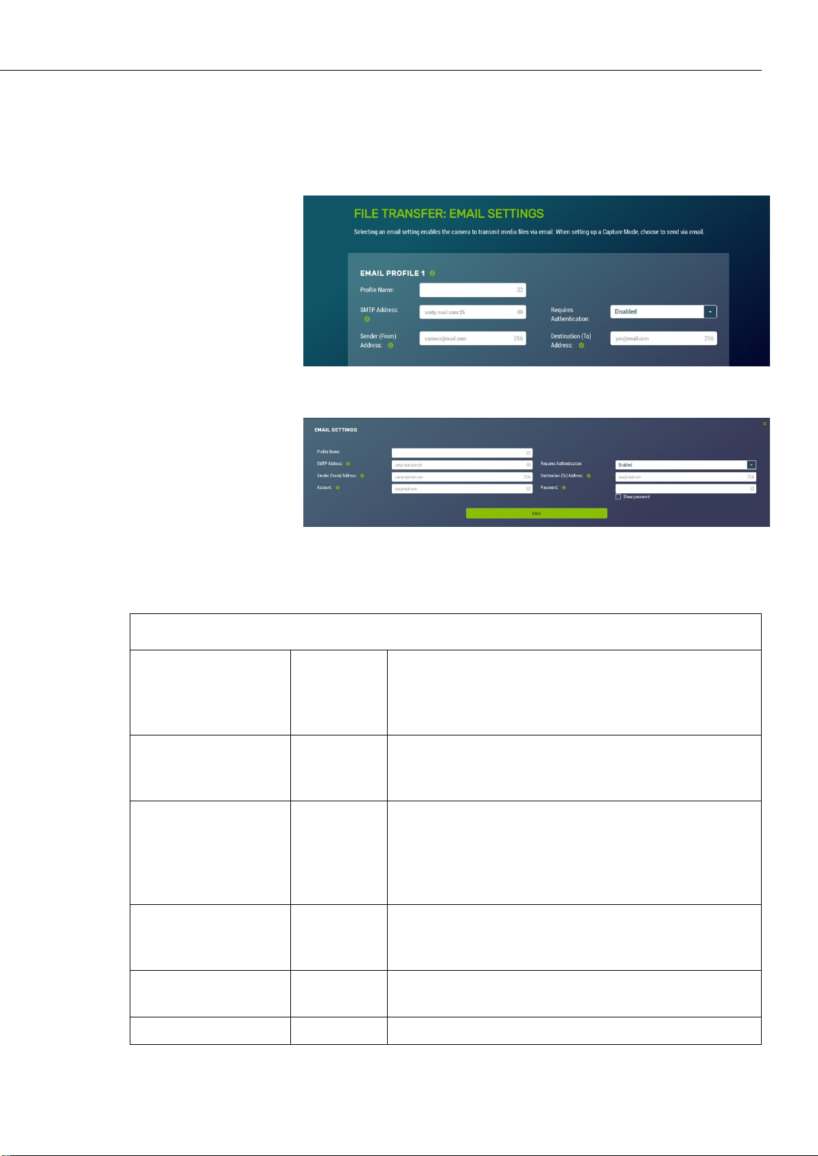
CCFC Field Camera
TABLE 12-22 Email Settings
Variable
Toggle,
Drop
Down, or
Text
Description
Profile Name
Text
Enter a name. This name will appear in the drop
down when setting up a Capture Mode (see Section
12.4 Capture Modes).
SMTP Address
Text
Enter the SMTP server address that is being used.
Enter the SMTP server port number as part of the
SMTP address, if required. The camera will default to
Port 25 if a value is not included.
Ex: mail.server.com:587.
Requires
Authentication
Drop down
Enable when email server requires authentication. If
Enabled, an Account and Password are required.
Disabled is the default setting.
Sender (From)
Address
Text
The Email address associated with the account is
normally used here. The CCFC cannot receive emails.
Destination (To)
Text
Recipient’s Email address. Multiple email addresses
In the event of a SMTP transfer failure, the CCFC will retry
sending the file to the mail server up to two times before aborting
the file transfer.
Figure 12-34 Email Settings
Figure 12-35 Email Settings Modal
71
Page 86

CCFC Field Camera
Address
can be entered. To use multiple email addresses,
separate them by a comma or semi-colon (ex:
test1@somewhere.com;john@email.com).
Account (only
required if
authentication is
used)
Text
An email address.
Password (only
required if
authentication is
used)
Text
Password associated with the email account.
Note
When troubleshooting email connectivity, use the
Show Password checkbox to ensure the password
entered is correct.
12.8.3.3 PakBus
PakBus is used to enable media files to be sent to a PakBus
compatible device (Campbell Scientific dataloggers). Ensure the
PakBus device is set up to receive (see LoggerNet Manual, which
is available for download at
http://www.campbellsci.ca/loggernet). Maximum file size that
can be sent is 2 MB.
Figure 12-36 PakBus Settings
72
Page 87

Figure 12-37 PakBus Modal
CCFC Field Camera
Communications using the PakBus protocol enables remote
retrieval and/or storage of photos or video to external devices
such as compatible Campbell Scientific dataloggers. Meaning,
photos can be stored on the datalogger, which allows for remote
retrieval using the datalogger’s communication device. Both RS232 and RS-485 are available. The preferred setting is determined
at the time of ordering. Contact Campbell Scientific for more
information.
Additionally, the PakBus neighbouring address allows for
communication with devices that are several hops away on the
PakBus network. Further information on PakBus is available in
Section 15 Send via PakBus: PakBus Communications.
73
Page 88

CCFC Field Camera
TABLE 12-23 PakBus Settings
Variable
Allowable
Values
Description
Not editable.
Displays as RS-232 or RS-485, depending on the option
selected at the time of purchase. (see Section 13 RS-232
Communications and Section 14 RS-485 Communications).
This value will appear when setting up a Capture Mode (see
Section 12.4 Capture Modes).
PakBus
Address
1 to 4095
Enter PakBus Address from 1 to 4095. The factory default is
55.
This should be a unique address in the PakBus network.
PakBus
Destination
1 to 4095
The PakBus address of the device the camera will
communicate with or send files to.
PakBus
Neighbour
0 to 4095
Physically enter the address of the PakBus device to connect
to the CCFC PakBus communication lines. This allows the
neighbour to relay communication between the CCFC and
the final destination for the data. 0 is autodetect.
Communication
Delay
1 to 16
Extra delays may be required for certain communication
links such as satellite.
Security Code
0 to 65535
The factory default is 0. If a security code is not required by
the PakBus destination device, set this parameter to 0.
Otherwise set the security code as required by the
destination service.
12.8.4 Camera Operation
12.8.4.1 Camera Power Modes
Figure 12-38 Camera Power Modes
74
Page 89

CCFC Field Camera
TABLE 12-24 Camera Power Modes
Power
Mode
Ethernet
Power Save
Mode
Operating Characteristics
Fully On
Always On
Camera is always on.
Highest power consumption.
Ethernet is on and always available for incoming
communications.
Moderate
Power Save
Mode
Not recommended.
Full Power
Save
Camera is always on.
Average power consumption is reduced by 50mA @ 12 Vdc.
The Ethernet is normally turned off and is only enabled when
outgoing communications are required (email or FTP).
User needs to push the Setup Button to temporarily enable the
Ethernet port for web page access.
Partially On
Always On
The camera is effectively off in a low powered state.
Typical power consumption is 90 mA @ 12 Vdc.
Ethernet is on and always available for incoming
communications.
The camera will temporarily wake up to the fully on power
mode when traffic occurs on the network.
Warning: In situations where there is constant network traffic,
the camera may effectively be in the Fully On power mode.
Moderate
Power Save
Mode
The camera is effectively off in a low powered state.
Typical power consumption is 60 mA @ 12 Vdc
Ethernet is enabled only for outgoing communications such as
The combination of the Camera Power Mode and Ethernet Power
Modes dictates the camera’s power draw. There are four Camera
Power Mode options:
Fully On State: used if no power constraints exist or if
high performance is required.
Partially On State: provides substantial reduction in
power.
Deep Sleep State: provides very good power savings.
Recommended for use if more than 24 triggers are
expected per day.
Off State: offers the best power savings. Useful if less
than 24 images or video captures are required per day.
75
Page 90

CCFC Field Camera
FTP or email.
Disconnecting and connecting the camera to another Ethernet
device will momentarily wake up the camera to allow it to
process incoming communications. The camera will go into the
low powered mode again – if no communications occur.
Full Power
Save Mode
The camera is effectively off in a low powered state.
Average power consumption is typically 10 mA @ 12 Vdc.
The Ethernet is normally turned off and is only enabled when
outgoing communications are required (email or FTP).
User needs to push the Setup Button to temporarily enable the
Ethernet port for web page access.
The camera can respond to RS-232 or RS-485 communication
in this mode.
Deep Sleep
Always On
The Deep Sleep power consumption (6mA typically) is not
affected by the Ethernet Power Mode.
Ethernet, RS-232 or RS-485 communications are nonresponsive in Deep Sleep mode.
Moderate
Power Save
Mode
Not recommended.
Full Power
Save Mode
The Deep Sleep power consumption (6 mA typically) is not
affected by the Ethernet Power Mode.
If Ethernet communications are not used this can reduce the
power consumption of the camera by 50mA when the camera
exits the Deep Sleep state.
Off State
Always On
The Off State power consumption (1 mA typically) is not
affected by the Ethernet Power Mode.
Ethernet, RS-232 and RS-485 communications are nonresponsive in the Off State.
Moderate
Power Save
Mode
Not recommended.
Full Power
Save Mode
The Off State power consumption (1 mA typically) is not
affected by the Ethernet Power Mode.
If Ethernet communications are not used, this can reduce the
power consumption of the camera by 50 mA when the camera
exits the Deep Sleep state.
76
Page 91

CCFC Field Camera
Note
TABLE 12-25 Capture Response Time
Power Mode
Typical Capture Time from Trigger Event
(seconds)
Fully On
< 1
Partially On
10
Deep Sleep
10
Off State
90
See Section 12.8.4.2 Ethernet Power Mode for other
settings that influence power consumption.
Capture response time shows typical response times from when a
trigger occurs to the time that a photo or video is taken. The Off
State takes the longest, as the main processor is not powered on in
this state and it must completely boot up to operate again from the
Off State.
12.8.4.2 Ethernet Power Mode
Ethernet Power Mode dictates the Ethernet power draw. To
reduce power consumption, the CCFC includes the ability to
control the power characteristics of the Ethernet port.
The specific behaviour of the camera’s Ethernet power save is
also influenced by the Power mode of the camera. Table 12-25
Ethernet Power Modes outlines the Ethernet power saving
features versus various camera power modes.
Figure 12-39 Ethernet Power Modes
77
Page 92

CCFC Field Camera
TABLE 12-26 Ethernet Power Modes
Power
Mode
Operating Characteristics
Always On
This power mode offers the maximum availability of the
Ethernet port. If the camera is in the Fully On power state or
the Partially On power state, then the Ethernet port will always
be on and available for communications.
Moderate
Power Save
Mode
This power mode offers some power savings on the Ethernet
port. This mode is only recommended if the camera is in
Partially On power mode. If the camera is in the Partially On
power mode, then incoming data packets will wake up the
camera for communications.
Full Power
Save Mode
This power mode should be used if the lowest power
consumption is desired and incoming Ethernet communications
are not required. File transfers after a capture still function
properly.
12.8.4.3 Wi-Fi Power Mode
Wi-Fi Power Mode allows a user to select how much power the
camera uses when the camera set to Wi-Fi Access Point in the
network settings. There are three power mode options to choose
from.
Figure 12-40 Wi-Fi Power Mode
The default setting for the Wi-Fi Power Mode is Always On.
78
Page 93

CCFC Field Camera
TABLE 12-27 Wi-Fi Power Modes
Power
Mode
Operating Characteristics
Always On
Wi-Fi connection is always powered on.
Low Power
Save Mode
Wi-Fi will only power up to transmit files after a capture event.
A button press enables the Wi-Fi for 5 min.
Attaching the external trigger wire (blue) to a power source
(>2.5 Vdc, maximum 30 Vdc) turns the Wi-Fi on until power is
removed.
Disabled
Wi-Fi connection is disabled (does not power up). Files cannot
be transmitted over Wi-Fi. A button press will enable the Wi-Fi
for 5 min, network activity will not reset this timer. Holding the
External Trigger in the active state enables the Wi-Fi.
Deactivating the External Trigger Input will immediately
power off the Wi-Fi.
One of the main factors in determining which power mode to use
is the power consumption budget available for the camera.
If the camera is operating from an AC main power supply, the
camera will have the best performance characteristics in the Fully
On State. On the other hand, if the camera needs to operate from
a battery for long periods of time, then the Off State is more
suitable.
There are two methods to wake the Wi-Fi up when it is
configured for a low power mode. First, pressing the Setup Button
on the back of the camera will wake the Wi-Fi out of Low Power
Save Mode and Disabled for 5 min. Any network activity on the
web interface will also reset the timer in Low Power Save Mode.
Network activity will not reset the timer in Disabled Mode.
Second, by holding the External Trigger Input in the active state,
the Wi-Fi will wake out of any low power mode after a period of
10 sec. Similarly, network activity will reset the 5 min timer in
Low Power Save Mode, but not in Disabled Mode.
12.8.4.4 Night Mode
The CCFC is optimized for night-time media captures. During
times of reduced light, the camera automatically increases its
exposure time and can lower the frame rate in order to increase
brightness in photos. The CCFC will also increase frame rate
when capturing videos, which results in videos that appear darker
than photos captured at the same time. The CCFC is equipped
with Infrared LEDs in order to capture photos in complete
79
Page 94

CCFC Field Camera
Warning
darkness. IR illumination can be turned on or off to suit low light
needs. The CCFC has an integrated IR filter that automatically
switches in and out of to suit the lighting conditions. This
optimizes photo quality in low light and daytime light.
Additionally, if enabled, the IR filter will switch out in the dark
without turning on the IR LEDs.
Figure 12-41 Night Mode
12.8.4.4.1 IR LED Power Control
The IR LEDs emit a very bright light that is
nearly invisible to the human eye. Do not
look directly at the front of the camera when
the LEDs are on, as they can cause severe
eye damage.
The infrared (IR) LEDs on the camera are used to take pictures
and video at night. To enable the IR LEDs, select the Night Mode
page.
When the IR LEDs are enabled, the camera will automatically
switch them on and off during photo or video capture when the
ambient light level drops too low. Generally, this happens shortly
after sunset outdoors. The IR LEDs remain on while the camera is
awake. If the camera is configured to use a low power mode, the
IR LEDs will turn off when the camera goes to sleep.
80
Page 95

Note
The IR LEDs and the lens defroster are multiplexed together, so
only one will operate at a time. In a situation where both the IR
LEDs and the defroster should be on, the IR LEDs take priority as
they also provide a significant amount of heat to the lens.
The IR LEDs emit light at 850 nm wavelength in a 12° cone from
the centreline. This is a fairly narrow beam angle, which
concentrates the light on the center of the photo, allowing distant
objects up to 36m (120 ft) away to be illuminated.
12.8.4.4.2 Filter Control
Outdoor photos contain a great deal of IR light from the sun. The
photo sensor in the CCFC is sensitive to this IR light and will
pick it up causing the photo to look improperly coloured. The lens
on the CCFC is equipped with a switchable IR filter to counteract
this effect.
The setting for the IR filter allows it to be enabled all the time or
disabled when the camera is in night mode, giving the camera
extra sensitivity in dark scenes without having to use the IR
LEDs.
CCFC Field Camera
When the IR LEDs are enabled and switched on, the IR filter
automatically switches off regardless of the IR filter setting.
12.8.4.4.3 Light Power Control
The Power Control wire can be used to control an external light
source or a relay that activates an external light source. The
camera can be configured to switch the external 12 Vdc (yellow
wire) on, based on the available light in the scene.
The light will only come on when capturing from a timed capture
or when an external trigger occurs while the camera is in sleep
mode. The light does not turn on for motion detect capture. The
light turns off after the capture is complete.
12.8.4.5 Digital I/O
The light and communication power control output
are in parallel on the same wire on the connector. If
both powers are enabled, the output remains on from
the start of capture to when the file transfer is
complete.
The Digital I/O page allows the configuration of the Modem
Power Control and Lens Defroster Control.
81
Page 96

CCFC Field Camera
12.8.4.5.1 Modem Power Control
Figure 12-42 Digital I/O Settings
The Modem Power Control setting controls the yellow Power I/O
signal line of the CCFC camera.
The yellow wire, or switch output, is intended to manage the
power to a communication device such as a cell modem. This is
useful in a solar powered site when there is a need to limit power
consumption of communication devices.
This option enables the CCFC to supply up to a maximum of 750
mA of current. The voltage level will be the same as the camera’s
input power (i.e. 12 Vdc).
Some modems require a warm up time or a period of time to
register on a network. The Early Power On option is there for this
purpose. Enter a value in seconds; the maximum value that can be
entered is 300. The default is 120 seconds.
Figure 12-43 Modem Power Control
In order to communicate via cell modem, set the CCFC’s wired
Ethernet settings to the appropriate values as per the cell
modem’s manual. The required values are IP Address, Netmask,
Default Gateway and Primary Nameserver. If the cell modem has
a firewall enabled, set up port forwarding to the camera. For
accessing the camera’s webpage, forward the HTTP port (default
80). To access the camera’s FTP server through the cell modem,
forward the camera’s FTP server port (21) and the port range
1024-1043.
82
Page 97

12.8.4.5.2 Lens Defroster Control
The Lens Defroster Control controls the operation of the lens
defroster. When enabled, the camera only turns on the lens
defroster if the internal temperature is below the threshold setting.
The temperature threshold values are limited between -40°C and
+25°C.
If Always On is selected, the heater will be on whenever the
temperature is below the threshold and the camera is not in a low
power state.
CCFC Field Camera
Figure 12-44 Lens Defroster Control: Always On
If Prior to Capture is selected, the camera will wake up prior to
any of the Timed Capture schedules and turn on the heater, if the
temperature is below the threshold settings. This feature does not
work in Motion Detect or External Trigger modes.
This is useful for a remote site that may be prone to riming and
frost. A camera that is setup to take hourly pictures can be
configured to turn on the defroster several minutes prior to the
scheduled picture to defrost the lens using the Prior to Capture
drop down option and inputting a value in minutes.
Figure 12-45 Lens Defroster Control: Prior to Capture
83
Page 98

CCFC Field Camera
12.8.5 Advanced
12.8.5.1 GPS
Photos created by the CCFC can be geotagged - GPS coordinates
can be embedded in the photo files metadata.
Figure 12-46 GPS
Options for GPS Settings are: Degrees, Minutes, Seconds or
Decimal Degrees.
When Degrees, Minutes, Seconds is selected, Latitude (North or
South) and Longitude (East and West) must be selected from the
drop down and numerical values for degrees, minutes, and
seconds must be inputted.
84
Figure 12-47 GPS: Degrees, Minutes, Seconds
When Decimal Degrees is selected, Latitude (-90.0000 to
90.0000) and Longitude (-180.0000 to 180.0000) values are
inputted.
Page 99

12.8.5.2 Import/Export
TABLE 12-28 Import/Export Settings
Variable
Options
Description
Upload
Configuration
File
Choose file
Uploads selected file from the computer.
This file can be found on the Campbell
Scientific website
http://www.campbellsci.ca/ccfc
Update IP
address settings
Checkbox
If selected, it updates IP address
information from the file.
Not selecting this will not update the IP
address information. This is useful, as
having two cameras with the same IP
address is not desirable.
CCFC Field Camera
Figure 12-48 GPS: Decimal Degrees
The Import/Export tool is used to maintain continuity between
cameras. It has the ability to import and export settings to and
from the CCFC camera. Additionally, Import/Export allows for
configuration settings to be uploaded or downloaded via the web
interface. The .xml configuration files are also compatible with
the Device Configuration Utility.
Figure 12-49 Import/Export Camera Settings
85
Page 100

CCFC Field Camera
Update Wi-Fi
settings
Checkbox
If selected, it updates Wi-Fi settings from
file.
Not selecting this will not change the WiFi settings.
Update PakBus
network
settings
Checkbox
If selected, it updates the PakBus settings
(see Section 12.8.3.3 PakBus).
Not selecting this will not update the
PakBus settings. This is useful, as having
two cameras with the same IP address is
not desirable.
Upload Button
Send the file with the selected update
settings to the camera and changes will be
applied.
It may be necessary to reconnect to the
camera if network settings were changed.
Download
Configuration
File
Download
Button
Downloads the configuration file to the
connected device.
Downloading the configuration file is
useful when setting up multiple cameras
with the same function. The option to
download the configuration file allows
easy transfer of data from one camera to
the other without having to duplicate work.
Save
Configuration
File to
Internal
Memory
Save Button
Saves the Configuration file to the camera
memory.
Saving configuration files to camera
memory can be useful for keeping a record
of previous configuration versions.
12.8.5.3 Update
Update provides the ability to update the firmware in the camera.
It is recommended to regularly check for firmware updates on the
Campbell Scientific website
https://www.campbellsci.ca/downloads to ensure that the camera
has the most recent version of firmware.
86
 Loading...