

Page 1

INSTRUCTION MANUAL
CCFC Field Camera
May 2016
Copyright © 2016
Campbell Scientific (Canada) Corp.
Page 2

Page 3

WARRANTY AND ASSISTANCE
This equipment is warranted by CAMPBELL SCIENTIFIC (CANADA) CORP. ("CSC") to
be free from defects in materials and workmanship under normal use and service for
twenty-four (24) months from date of shipment unless specified otherwise.
Batteries are not warranted. ***** CSC's obligation under this warranty is limited to
repairing or replacing (at CSC's option) defective products. The customer shall assume
all costs of
removing, reinstalling, and shipping defective products to CSC. CSC will
return such products by surface carrier prepaid. This warranty shall not apply to any
CSC products which have been subjected to modification, misuse, neglect, accidents of
nature, or shipping damage. This warranty is in lieu of all other warranties, expressed or
implied, including warranties of merchantability or fitness for a particular purpose. CSC
is not
liable for special, indirect, incidental, or consequentia l damages.
Products may not be returned without prior authorization. To obtain a Return
Merchandise Authorization (RMA), contact CAMPBELL SCIENTIFIC (CANADA) CORP.,
at (780) 454-2505. An RMA number will be issued in order to facilitate Repair Personnel
in identifying an instrument upon arrival. Please write this number clearly on the outside
of the shipping container. Include description of symptoms and all pertinent details.
CAMPBELL SCIENTIFIC (CANADA) CORP. does not accept collect calls.
Non-warranty products returned for repair should be accompanied by a purchase order to
cover repair costs.
*****
Page 4

Precautions
DANGER — MANY HAZARDS ARE ASSOCIATED WITH INSTALLING, USING, MAINTAINING, AND WORKING ON OR AROUND
TRIPODS, TOWERS, AND ANY ATTACHMENTS TO TRIPODS AND TOWERS SUCH AS SENSORS, CROSSARMS, ENCLOSURES,
ANTENNAS, ETC. FAILURE TO PROPERLY AND COMPLETELY ASSEMBLE, INSTALL, OPERATE, USE, AND MAINTAIN TRIPODS,
TOWERS, AND ATTACHMENTS, AND FAILURE TO HEED WARNINGS, INCREASES THE RISK OF DEATH, ACCIDENT, SERIOUS
INJURY, PROPERTY DAMAGE, AND PRODUCT FAILURE. TAKE ALL REASONABLE PRECAUTIONS TO AVOID THESE HAZARDS.
CHECK WITH YOUR ORGANIZATION'S SAFETY COORDINATOR (OR POLICY) FOR PROCEDURES AND REQUIRED PROTECTIVE
EQUIPMENT PRIOR TO PERFORMING ANY WORK.
Use tripods, towers, and attachments to tripods and towers only for purposes for which they are designed. Do not exceed design
limits. Be familiar and comply with all instructions provided in product manuals. Manuals are available at www.campbellsci.ca or by
telephoning (780) 454-2505 (Canada). You are responsible for conformance with governing codes and regulations, including safety
regulations, and the integrity and location of structures or land to which towers, tripods, and any attachments are attached. Installation
sites should be evaluated and approved by a qualified personnel (e.g. engineer). If questions or concerns arise regarding installation,
use, or maintenance of tripods, towers, attachments, or electrical connections, consult with a licensed and qualified engineer or
electrician.
General
x Prior to performing site or installation work, obtain required approvals and permits.
x Use only qualified personnel for installation, use, and maintenance of tripods and towers, and
any attachments to tripods and towers. The use of licensed and qualified contractors is
highly recommended.
x Read all applicable instructions carefully and understand procedures thoroughly before
beginning work.
x Wear a hardhat and eye protection, and take other appropriate safety precautions while
working on or around tripods and towers.
x Do not climb tripods or towers at any time, and prohibit climbing by other persons. Take
reasonable precautions to secure tripod and tower sites from trespassers.
x Use only manufacturer recommended parts, materials, and tools.
Utility and Electrical
x You can be killed or sustain serious bodily injury if the tripod, tower, or attachments you are
installing, constructing, using, or maintaining, or a tool, stake, or anchor, come in contact
with overhead or underground utility lines.
x Maintain a distance of at least one-and-one-half times structure height, 6 meters (20 feet), or
the distance required by applicable law, whichever is greater, between overhead utility lines
and the structure (tripod, tower, attachments, or tools).
x Prior to performing site or installation work, inform all utility companies and have all
underground utilities marked.
x Comply with all electrical codes. Electrical equipment and related grounding devices should
be installed by a licensed and qualified electrician.
Elevated Work and Weather
x Exercise extreme caution when performing elevated work.
x Use appropriate equipment and safety practices.
x During installation and maintenance, keep tower and tripod sites clear of un-trained or non-
essential personnel. Take precautions to prevent elevated tools and objects from dropping.
x Do not perform any work in inclement weather, including wind, rain, snow, lightning, etc.
Maintenance
x Periodically (at least yearly) check for wear and damage, including corrosion, stress cracks,
frayed cables, loose cable clamps, cable tightness, etc. and take necessary corrective actions.
x Periodically (at least yearly) check electrical ground connections.
WHILE EVERY ATTEMPT IS MADE TO EMBODY THE HIGHEST DEGREE OF SAFETY IN ALL CAMPBELL SCIENTIFIC PRODUCTS,
THE CLIENT ASSUMES ALL RISK FROM ANY INJURY RESULTING FROM IMPROPER INSTALLATION, USE, OR MAINTENANCE OF
TRIPODS, TOWERS, OR ATTACHMENTS TO TRIPODS AND TOWERS SUCH AS SENSORS, CROSSARMS, ENCLOSURES, ANTENNAS,
ETC.
Page 5

Table of Contents
PDF viewers: These page numbers refer to the printed version of this document. Use the
PDF reader bookmarks tab for links to specific sections.
1. Introduction ................................................................ 1
2. Specifications ............................................................. 1
3. Initial Inspection ......................................................... 3
4. Quick Notes ................................................................ 3
4.1 CCFC General ...................................................................................... 3
4.2 Campbell Dataloggers Users ................................................................ 4
4.3 Configuration Process .......................................................................... 5
5. Cautionary Statements .............................................. 6
6. Factory Setup ............................................................. 7
7. Camera Hardware ....................................................... 8
7.1 Power I/O Connection .......................................................................... 9
7.2 Setup Button/Status LED ..................................................................... 9
7.2.1 Status LED .................................................................................... 9
7.2.2 Setup Button ............................................................................... 10
7.3 Camera Memory ................................................................................ 10
7.3.1 Link to Most Recent Photo and Video ........................................ 10
7.3.2 FTP Photo Collection from Camera Memory ............................. 11
7.4 Modem Power Control ....................................................................... 12
7.5 Lens .................................................................................................... 12
7.5.1 Camera Lens and Field of View ................................................. 12
7.5.2 Camera Auto Focus .................................................................... 12
7.5.3 Temperature Variations and Focus ............................................. 13
7.5.4 Lens IR Cut Filter ....................................................................... 13
8. Cables/Wiring ........................................................... 13
8.1 Power & I/O Cable Connections ........................................................ 13
8.2 Power & I/O Cable Details ................................................................ 15
8.3 Ethernet Cables .................................................................................. 15
9. Using Device Configuration Utility ......................... 16
10. Photo Quality ............................................................ 17
11. Connecting to the Web Interface ............................ 17
11.1 Setup Using Wi-Fi ............................................................................. 18
11.2 Setup Using Ethernet ......................................................................... 18
i
Page 6

Table of Contents
Link Local IP Address Auto-Configuration ............................... 18
11.2.1
12. Camera Operation using the Web Interface ........... 18
12.1 Installing MultiMedia Pla yer ............................................................. 19
12.1.1 RTSP Video Stream ................................................................... 19
12.1.1.1 Sources ............................................................................ 19
12.1.1.2 Embedding ....................................................................... 20
12.1.2 UPnP Discovery ......................................................................... 20
12.2 Web Interface Overview ................................................................... 20
12.2.1 Live Video Modal ...................................................................... 23
12.2.2 Power Icon ................................................................................. 24
12.2.3 Set Up Progress Bar ................................................................... 24
12.3 Dashboard ......................................................................................... 25
12.4 Capture Modes .................................................................................. 26
12.4.1 Timed Capture ............................................................................ 27
12.4.2 External Trigger ......................................................................... 31
12.4.3 Motion Detect ............................................................................ 35
12.5 Lens Position ..................................................................................... 39
12.6 Media Settings ................................................................................... 41
12.6.1 Photo Capture ............................................................................. 42
12.6.2 Video Capture ............................................................................ 45
12.7 File Explorer ...................................................................................... 47
12.8 Settings .............................................................................................. 48
12.8.1 General ....................................................................................... 48
12.8.1.1 SNTP ............................................................................... 49
12.8.2 Network ...................................................................................... 50
12.8.2.1 Wired Ethernet Settings ................................................... 51
12.8.2.2 Wi-Fi Settings .................................................................. 52
12.8.2.3 Wi-Fi Access Mode ......................................................... 53
12.8.2.3.1 Wi-Fi Access Point ............................................... 53
12.8.2.3.2 Existing Network .................................................. 54
12.8.3 File Transfer ............................................................................... 56
12.8.3.1 FTP .................................................................................. 56
12.8.3.2 Email ............................................................................... 57
12.8.3.3 PakBus ............................................................................. 59
12.8.4 Camera Operation ...................................................................... 61
12.8.4.1 Camera Power Modes ...................................................... 61
12.8.4.2 Ethernet Power Mode ...................................................... 63
12.8.4.3 Wi-Fi Power Mode .......................................................... 64
12.8.4.4 Night Mode ...................................................................... 65
12.8.4.4.1 LED Power Control .............................................. 66
12.8.4.4.2 Filter Control ........................................................ 66
12.8.4.4.3 Light Power Control ............................................. 66
12.8.4.5 Digital I/O ........................................................................ 67
12.8.4.5.1 Modem Power Control ......................................... 67
12.8.4.5.2 Lens Defroster Control ......................................... 68
12.8.5 Advan ced ................................................................................... 69
12.8.5.1 GPS .................................................................................. 69
12.8.5.2 Import/Export .................................................................. 70
12.8.5.3 Update ............................................................................. 71
12.8.5.4 Users ................................................................................ 72
12.8.5.5 History ............................................................................. 73
13. RS-232 Communications ......................................... 74
ii
Page 7

14. RS-485 Communications ......................................... 76
15. Send Via PakBus: PakBus Communications ......... 76
15.1 Send Via PakBus: Concurrent PakBus Communications .................. 77
15.2 Send Via PakBus: PakBus Graph Operations .................................... 77
15.2.1 Dataogger Settings ...................................................................... 77
15.2.2 Discovery .................................................................................... 77
15.3 Setting Up Datalogger to Work with CCFC: PakBus Variable Control
........................................................................................................ 77
15.3.1 PakBus Control of Window Defroster Function ......................... 78
15.3.2 PakBus Control of CCFC Power ................................................ 79
15.3.3 Example Program – SendVariable Instruction – CR1000........... 79
15.3.4 Example Program – Adding GPS Coordinates to the Photo Banner
– CR1000 ................................................................................. 80
15.4 PakBus Neighbouring Address .......................................................... 81
16. Power Calculations and Timings ............................ 81
16.1 Standalone Operation ......................................................................... 81
16.2 Operation with Communications ....................................................... 82
17. CCFC Compatability ................................................ 84
18. CR1000 Interface Guide ........................................... 84
18.1 CR1000 Memory Setup ..................................................................... 84
18.2 CR1000 Files Manager ...................................................................... 85
18.3 CR1000 COM Port (Control Port) Communications ......................... 86
19. Remote Photo Retrieval ........................................... 86
19.1 LoggerNet File Retrieval ................................................................... 86
19.2 Using LoggerNet File Control ........................................................... 88
20. Mounting ................................................................... 89
21. Maintenance ............................................................. 91
21.1 Lithium Battery .................................................................................. 91
21.2 Window and Lens Cleaning ............................................................... 91
22. System Limitations .................................................. 91
22.1 High Resolution 5 Megapixel Photos................................................. 91
22.2 Simultaneous Processes ..................................................................... 91
Append ix A. CCFC Camera Accessories ................. A-1
A.1 CCFCCBL1-L Power & I/O Cable ................................................. A-1
A.2 CCFCCBL2-L Environmental Ethernet Cable................................ A-1
A.3 L18549 Mounting Kit ..................................................................... A-2
A.4 L28840 DB9 FEMALE To Terminal Block Adaptor ..................... A-2
Page 8

Table of Contents
Figures
Figure 1-1 CCFC Camera ............................................................................... 1
Figure 7-1 CCFC Connector Layout ............................................................... 8
Figure 7-2 Photo Collection from Installed Camera Memory ....................... 11
Figure 9-1 CCFC shown in Device Configuration Utility ............................ 17
Figure 12-1 Dashboard - Desktop view ........................................................ 21
Figure 12-2 Dashboard - Mobile views ........................................................ 21
Figure 12-3 Top Navigation Bar – Desktop view ......................................... 23
Figure 12-4 Live Video Modal ...................................................................... 24
Figure 12-5 Set Up Progress bar ................................................................... 24
Figure 12-6 CCFC Dashboard ...................................................................... 25
Figure 12-7 Manual Capture Modal .............................................................. 26
Figure 12-8 Timed Capture ........................................................................... 27
Figure 12-9 Timed Capture: Create New Profile .......................................... 28
Figure 12-10 External Trigger ...................................................................... 31
Figure 12-11 External Trigger: Create New Profile ..................................... 32
Figure 12-12 Motion Detect .......................................................................... 35
Figure 12-13 Motion Detect: Create New Profile ......................................... 36
Figure 12-14 Lens Position ........................................................................... 39
Figure 12-15 Lens Position Modal ................................................................ 40
Figure 12-16 Lens Position Modal (in Capture Modes) ................................ 40
Figure 12-17 Media Settings ......................................................................... 41
Figure 12-18 Media Settings: Edit Photo Profile .......................................... 42
Figure 12-19 Photo Settings Modal .............................................................. 42
Figure 12-20 Media Settings: Edit Video Profile .......................................... 45
Figure 12-21 Video Settings Modal ............................................................... 45
Figure 12-22 File Explorer: Camera Memory Details .................................. 47
Figure 12-23 File Explorer: File Details ....................................................... 47
Figure 12-24 General Settings ...................................................................... 48
Figure 12-25 Date and Time Settings: Sync with SNTP Server ................... 50
Figure 12-26 Network ................................................................................... 50
Figure 12-27 Network Pop-up on Google Chrome ....................................... 51
Figure 12-28 Wired Ethernet Settings ........................................................... 51
Figure 12-29 Wi-Fi Settings .......................................................................... 52
Figure 12-30 Access Point Settings ............................................................... 53
Figure 12-31 Connect to Existing Network ................................................... 54
Figure 12-32 FTP Settings ............................................................................ 56
Figure 12-33 FTP Settings Modal ................................................................. 56
Figure 12-34 Email Settings .......................................................................... 58
Figure 12-35 Email Settings Modal .............................................................. 58
Figure 12-36 PakBus Settings ....................................................................... 59
Figure 12-37 PakBus Modal ......................................................................... 59
Figure 12-38 Camera Power Modes ............................................................. 61
Figure 12-39 Ethernet Power Modes ............................................................ 63
Figure 12-40 Wi-Fi Power Mode .................................................................. 64
Figure 12-41 Night Mode .............................................................................. 65
Figure 12-42 Digital I/O Settings .................................................................. 67
Figure 12-43 Modem Power Control ............................................................ 67
Figure 12-44 Lens Defroster Control: Always On ........................................ 68
Figure 12-45 Lens Defroster Control: Prior to Capture ............................... 68
Figure 12-46 GPS.......................................................................................... 69
Figure 12-47 GPS: Degrees, Minutes, Seconds ............................................ 69
Figure 12-48 GPS: Decimal Degrees............................................................ 70
Figure 12-49 Import/Export Camera Settings ............................................... 70
Figure 12-50: Update .................................................................................... 71
iv
Page 9

Tables
Figure 12-51 Users and Security Settings ...................................................... 72
Figure 12-52 History ...................................................................................... 74
Figure 13-1 PakBus Settings .......................................................................... 74
Figure 13-2 L28840 DB9 FEMALE to Terminal Block Adapter .................. 75
Figure 19-1 File Retrieval Setup Screen ........................................................ 87
Figure 19-2 Loggernet Connection Screen .................................................... 88
Figure 19-3 USR Drive View in File Control ................................................ 89
Figure 20-1 CCFC Mounting Kit ................................................................... 89
Figure 20-2 CCFC Mounting Holes .............................................................. 90
Figure 20-3 CCFC Mounted to Crossarm ...................................................... 90
Table 4-1 Power Mode Summary .................................................................... 5
Table 6-1 CCFC Factory Default Configuration ............................................. 7
Table 7-1 Setup Button Status LED................................................................. 9
Table 8-1 Power & I/O Cable Connections ................................................... 14
Table 9-1 RS-232 Wiring Diagram ............................................................. 16
Table 12-1 Video Stream Sources ............................................................... 19
Table 12-2 Web Interface Components ......................................................... 22
Table 12-3 Dashboard Components ............................................................... 26
Table 12-4 Timed Capture Variables for Photos ........................................... 28
Table 12-5 Timed Capture Variables for Videos ........................................... 30
Table 12-6 External Trigger Variables for Photos ......................................... 32
Table 12-7 External Trigger Variables for Video .......................................... 34
Table 12-8 Motion Detect Settings for Photo Options ................................... 36
Table 12-9 Motion Detect Settings for Video Options .................................. 38
Table 12-10 Lens Positions Modal ................................................................ 41
Table 12-11 Photo Capture Variables ............................................................ 43
Table 12-12 Photo Resolution Details ........................................................... 44
Table 12-13 Video Capture Variables ........................................................... 46
Table 12-14 Typical Video File Sizes ........................................................... 46
Table 12-15 General Settings Variables ........................................................ 49
Table 12-16 Wired Ethernet Settings ............................................................. 52
Table 12-17 Wi-Fi Settings ............................................................................ 53
Table 12-18 Access Point Settings ................................................................ 54
Table 12-19 Exisitng Network Settings for Wi-Fi Clients ............................. 55
Table 12-20 FTP Settings .............................................................................. 57
Table 12-21 Email Settings ............................................................................ 58
Table 12-22 PakBus Settings ......................................................................... 60
Table 12-23 Camera Power Modes................................................................ 61
Table 12-24 Capture Response Time ............................................................. 63
Table 12-25 Ethernet Power Modes .............................................................. 64
Table 12-26 Wi-Fi Power Modes .................................................................. 64
Table 12-27 Import/Export Settings .............................................................. 70
Table 12-28 Users .......................................................................................... 73
Table 13-1 CCFC Connections to RS-232 Port ............................................. 75
Table 13-2 Datalogger Connections to RS-232 Port...................................... 75
Table 16-1 File Transfer Times Using PakBus .............................................. 83
Table 17-1 CCFC Compatibility with Contemporary and Retired Dataloggers
........................................................................................................ 84
Page 10

Page 11

CCFC Field Camera
1. Introduction
Figure 1-1 CCFC Camera
The CCFC is designed to meet the stringent operational requirements necessary
for remote battery powered installations, while producing HD video and photos
of up to 5 megapixels. The CCFC can operate over a wide temperature range
and has several advanced power saving modes to suit a variety of needs.
The CCFC incorporates an integrated rugged environmental enclosure to
reduce cost and installation time. Communication options include Ethernet,
Wi-Fi, RS-232, and RS-485. The CCFC is fully web-enabled with HTTP, FTP,
and Email capabilities. Campbell Scientific’s PakBus protocol is supported by
the CCFC for integration with Campbell Scientific dataloggers.
The camera contains an onboard camera memory that enables the camera to
function as a powerful photo and video datalogger. The internal 16GB camera
memory enables the CCFC to archive photos and video internally.
The CCFC can operate in a stand-alone mode with photo acquisitions triggered
by the camera’s own precision real time clock. Media (photo and video)
acquisitions can also be triggered by events through an external trigger or
motion detect.
2. Specifications
Power Supply Operating
x 9 – 30 Vdc Input voltage
x 250 mA at 12 Vdc nominal
x 1.4 A at 12 Vdc with window defroster enabled (heater is active)
x Quiescent: <1 mA (Off Power mode)
General
x Operating Temperature: -40°C to + 60°C
x Weight: 2.4 kg (5.25 lb)
x Clock Accuracy: ± 2 Minutes/Year (-40°C to +60°C)
1
Page 12

CCFC Field Camera
Dimensions
x Length: 28.4 cm (11.2”)
x Height: 13.0 cm (5.1”)
x Width: 13.2 cm (5.2”)
Lens
x Lens: 4.7 to 84.5 mm, 3° to 55° horizontal field of view
Photo or Video Capture Triggers
x Two Independent Self Timers
x Motion Detect
x Web Page Contr ol
x External Trigger
Photo and Video Capture Times (from wake up to start of capture)
x Fully On: < 1 s (5 MP images take longer; using lens positions adds
time)
x Partially On: 10 s
x Deep Sleep: 10 s
x Off State: 90 s
Photo Resolutions (JPEG)
x 2592 x 1944
x 1200 x 960
x 1280 x 720
x 640 x 480
x 640 x 352
x 320 x 240
x 320 x 176
Video Recording
x MPEG4 720p
x MPEG4 320 x 240
Video Frame Rate Options: 30, 15, and 7.5 frames per second (FPS)
External Trigger Signal
x Logic Low Level: < 0.65 V (-20 Vdc Absolute Min)
x Logic High Level: > 2.0 Vdc (+20 Vdc Absolute Max)
Communication Interfaces
x
Ethernet 10/100
x RS-232 port or RS-485 port
x Wi-Fi (supports 802.11bgn in the 2.4 GHz ISM band on channels 1-
11)
Communication Protocols
x Web page interface via web browser
x FTP
x Email
x PakBus (for Campbell Scientific dataloggers)
2
Page 13

CCFC Field Camera
Note
Modem Power Control
x Maximum Output Current: 750 mA
x 12 Vdc
RS-232 or RS-485
x Maximum Baud rate: 115.2 KBaud
For RS-232: The maximum recommended cable length at 115.2 K
BAUD rate is 15 m. The use of the 57.6 KBAUD rate has a
recommended maximum cable length of 30 m (90 ft).
For RS-485: A user-supplied (twisted pair) cable could be spliced
onto the communication wires to extend to a maximum cable
length of 305 m (1000 ft). Power wires still need to be kept to the
20 m (65 ft) factory length (or 0.7 Ohm user-supplied spliced
cable) limit.
Camera Memo ry
x File Type: jpeg (photo); avi (video)
x Size: 16 GB
Zoom
x 18x Optical zoom
3. Initial Inspection
x Upon receipt of the CCFC, inspect the packaging and contents for damage.
File any damage claims with the shipping company. Immediately check
package contents against the shipping documentation. Contact Campbell
Scientific about any discrepancies.
x The model number and cable length are printed on a label at the
connection end of the cable (if a cable was purchased). Check this
information against the shipping documents to ensure the expected product
and cable length are received.
x The CCFC is shipped with a Quick Start Guide, 2 scre ws, 2 lock washers,
2 flat washers, 4 Lens wipes, a ResourceDVD, and the Female DB9 to
Terminal block adaptor (L28840).
4. Quick Notes
4.1 CCFC General
x The LED will flash when the camera is in an Active Power State.
x When the LED is steadily on, the camera is booting up. Avoid
interrupting this process.
3
Page 14

CCFC Field Camera
x Briefly pressing the Setup Button always causes the camera to exit
from any low powered quiescent states and enables the Ethernet
interface for communications. The camera will remain in this state for
5 minutes.
x An active session to the camera with a web browser prevents the
camera from entering a low powered state.
x Avoid removing power from the camera when it is in an active state.
If the camera is in an active state (LED is flashing), properly
shutdown the camera to avoid any memory corruption before
removing power. The camer a can be shut down by holding the Setup
Button continuously for more than 10 seconds or by using the Power
Icon on the web interface.
x Always ensure that all cable connectors and covers are securely in
place.
x Record any changes to the IP settings of the camera. This information
is important to gain access to the camera for focusing or
reconfiguration.
x The camera configuration file can be imported or exported via the web
interface. This feature can be found under Import/Export.
x Check the Campbell Scientific website for firmware updates that may
apply.
4.2 Campbell Dataloggers Users
x If interfacing to a datalogger, ensure that the datalogger has the latest
PakBus opera t i ng system.
x Use either the CCFC built in-web interface, the Device Configuration
Utility, or PakBus Graph to change settings in the camera.
x Use the Device Configuration Utility to change settings in MD485 or
other PakBus devices.
x The Device Configuration Utility can also be used to set the
datalogger memory and PakBus parameters.
x Files (pictures or video) must be less than 2 MB for PakBus
transmissions.
x The datalogger instruction SendVariable can be used to send variables
or text to the camera, for use in photo or video captions. The
instruction can also be used to control the window defroster.
4
Page 15

Table 4-1 Power Mode Summary
Power
Mode
Ethernet
Power Save
ode
Quiescent
Current Draw
Max.@12
Vdc
Time (Seconds)
from wakeup to
start of capture
Time (Seconds) in Fully
On Mode (Active
Current Draw)
Fully On
Always On
0 – Always Active
Full Power
Save Mode
0 – Always Active
Partially On
Always On
Full Power
Save Mode
Deep Sleep
Always On
Full Power
Save Mode
Off State
Always On
Full Power
Save Mode
4.3 Configuration Process
1. Determine what will trigger the capture of a photo or video. Options include:
a. Timed Capture – Enable and configure Timed Capture 1, Timed Capture
2, or both. To set this up using the web interface, see Section 12.4.1 Timed
Capture.
b. External Trigger – Enable and configure the External Trigger Capture. To
set this up using the web interface, see Section 12.4.2 External Trigger.
c. Motion Detect – Enable and configure Motion Detect Capture. To set this
up using the web interface, see Section 12.4.3 Motion Detect.
2. Select the Power Mode that best suits the requirements (see Table 4-1 Power
Mode Summary). Options are:
a. Fully On – Used if no power contraints exist or if high performance is
required.
b. Partially On – Provides substantial reduction in power (especially with
the Ethernet Power Mode set to Full Power Save).
CCFC Field Camera
c. Deep Sleep – Provides very good power savings. The camera does not
need to reboot when activated by a trigger. Recommended for use if more
than 24 trigeers are expected per day.
d. Off Mode – Offers the best power savings. Useful, if less than 24 photos
or video captures are required per day. It takes about 90 seconds for the
camera to wake up to start acquiring a picture.
M
250 mA
200 mA
90 mA 10 20
10 mA 10 20
6 mA 15 25
6 mA 15 25
< 1
< 1
1 mA 90 120
1 mA 90 120
5
Page 16

CCFC Field Camera
3. Set the details of the media event
a. Set the photo settings
b. Set the video settings
4. Set other details related to Communications and I/O. These other parameters
are located under:
a. Section 12.8.2 Network.
b. Section 12.8.4.5 Digital I/0.
c. Section 13 RS-232 Communications and Section 14 RS-485
Communications.
5. Cautionary Statements
x Although the CCFC is designe d to be a rugged and reliable device for field
use, care should be taken when handling or moving it to avoid aesthetic
damage.
x Other than the desiccant, there are no user-serviceable parts. Improper
disassemply or re-assembly of the device will void the warranty. Contact
Campbell Scientific Canada or the reseller for details.
The CCFC has three warning stickers on the bottom of the camera:
1. IR Warning Sticker.
2. FCC Information Sticker.
6
Page 17

Table
Configuration Setting
Power Mode
Fully On State
Wi
10.0.01
Link Local IP
169.254.99.99
Ethernet Network IP Address
Acquired automatically using DHCP
Serial I/O Port
RS
-232 or RS-485
RS
115200
PakBus Address
55
3. Model #, Serial #, and MAC Address Sticker.
CCFC Field Camera
6. Factory Setup
Table 6-1 outlines the CCFC factory settings that are relevant for initially
communicating with the camera.
-Fi IP Address
-232 Baud Rate
6-1 CCFC Factory Default Configuration
Value
7
Page 18

CCFC Field Camera
Ethernet
Power I/O
(9
30 Vdc)
Setup Button
LED Status
Antenna
There are two methods for a user to configure the CCFC camera: using the web
interface via Wi-Fi or Ethernet connection and using the RS-232 serial lines.
Using the web interface is the best way to set up the camera. Communicate
with the camera via the Ethernet connection or Wi-Fi in order to facilitate
focusing and targeting the camera when installed.
Setting up the camera using the RS-232 (or RS-485) serial lines on the Power
I/O cable and using Campbell Scientific’s Device Configuration software to
change configuration parameters in the camera is an alternate to using the web
interface. Device Configuration Utility is a free download from the Campbell
Scientific (Canada) website www.campbellsci.ca/downloads. The use of RS232 serial lines requires the use of the DB9 terminal block adapter (included in
the box with the CCFC) in order to connect to a PC (Section 7.1 Power & I/O
Cable Connections).
7. Camera Hardware
Ensure that the pigtail end of the power cable is properly terminated (see
Section 8 Cables/Wiring) before connecting the power cable connector to the
camera. If the power supply has an on/off switch, it is recommended to switch
the power off before connecting the power connector to the camera.
When power is first applied to the camera, the LED on the Setup Button will
turn on and remain steadily on for about 90 seconds. Once the LED starts
flashing, the camera has properly initialized and is ready for operation (see
Section 7.2 Setup Button/Status LED).
-
8
Figure 7-1 CCFC Connector Layout
Page 19

Table 7-1 Setup Button Status LED
Continuously Off
No power or the camera is in one of
the following
odes:
Pressing the Setup Button
forces
the camera to exit
any of the low powered modes and remain
Fully
On
for a period of 5 min with the LED rapidly
flashing.
Slow Flash
1 sec on, 3 sec off
Normal Operation in Fully On
p
ower mode.
Rapid Flash
Exit from low power state. The
camera is being kept on by:
Communications
Asserted External Trigger
Photo or video acquisition
Continuously On
The camera is booting up
process takes approximately 90 sec.
The camera will be required to boot up whenever:
Power mode
7.1 Power I/O Connection
Connection to the Power I/O connector is necessary for camera operation, as it
is the only means to supply power to the camera. The connector that connects
to the Power I/O connector provides a weather-tight connection and has an
IP68 environmental rating when properly connected. Even when the camera is
not in use, the power cable must be left connected, if the camera is to be left
installed.
When connecting the cable to the camera, the notch positions must always line
up.
7.2 Setup Button/Status LED
The Setup Button is located behind a protective cap on the camera. The Setup
Button also contains an integrated Status LED for user feedback.
7.2.1 Status LED
The Status LED located in the center of the Setup Button provides some useful
diagnostic information about the camera. Table 7-1 describes the Status LED
behavior. This assumes the power supply is between 9 - 30 Vdc.
CCFC Field Camera
LED CCFC State Other
low powered m
x Partially On
x Deep Sleep
x Off Mode
x Timeout (from the Setup
Button press)
x Network
x
x
- this
x Power is first applied to it.
x The camera is exiting the Off
to perform an operation.
9
Page 20

CCFC Field Camera
Note
7.2.2 Setup Button
7.3 Camera Memory
The Setup Button can be used to wake the camera from any of the power
saving modes. Once the Setup Button is pushed, the CCFC enters a fully
powered mode for 5 minutes. During this interval, the camera can be accessed
via Ethernet, Wi-Fi, or RS-232/485 to make any necessary configuration
changes. If no communication occurs during the 5 minute window, the camera
will return to its configured power saving mode and continue normal operation.
Any button press, web interface, or FTP access resets the timer, keeping the
camera awake for another 5 min, on both the wireless and Wi-Fi connections.
The secondary function of the Setup Button is to facilitate a power down
procedure. If the button is held for 10 seconds, the camera will completely shut
down for a period of 10 min. After the 10 min, the camera will power up
again.This function is also available through the web interface via the power
icon (green) in the top right corner on the desktop version. On the mobile
version of the web interface, a Power Off navigation option appears at the
bottom of the sidebar.
The CCFC is equipped with 16GB of internal memory.
Photo files are stored on the camera memory as jpeg files and video files are
stored as avi files. Individual photo and video files are uniquely named
including a sequence number or a date and time stamp (Section 12.6 Media
Settings). The File Explorer on the user interface acts as a directory for the
camera memory. The user inputted media file Title will be used to organize the
photos in the directory. This is set up Media Settings (see Section 12.6 Media
Settings).
The use of camera memory for media storage is entirely configurable to suit
the needs of any given application. Individual photo or video capture can be
configured to manage camera memory as either Fill and Stop or Continuous
Overwrite (see Tables 12-4 to 12-9 inclusive).
See Section 12.7 File Explorer for more information on photo and video
retrieval from the camera memory. It is recommended to delete older files from
the camera memory after downloading them to a permanent storage location.
7.3.1 Link to Most Recent Photo and Video
To view the most recent photo and video, type one of the links below into the
computer or device browser. These links redirect to the actual files on the
camera memory, which means that the downloaded file name will be the same
as the file name on the camera memory to ensure continuity.
The following are examples. The IP address will vary with the
camera’s network configuration.
x Timed Capture 1:
10
o http://1.2.3.4/stc1.jpg
o http://1.2.3.4/stc1.avi
Page 21

Note
x Timed Capture 2:
o http://1.2.3.4/stc2.jpg
o http://1.2.3.4/stc2.avi
x External Trigger:
o http://1.2.3.4/etc.jpg
o http://1.2.3.4/etc.avi
x Motion Detect:
o http://1.2.3.4/mdc.jpg
o http://1.2.3.4/mdc.avi
7.3.2 FTP Photo Collection from Camera Memory
If the camera is setup to store photos to the camera memory, it may be
necessary to collect all the photos from the camera memory. The web interface
provides a user-friendly method of viewing and saving select files from the
camera memory through the File Explorer (Section 12.7). However, if it is
desired to collect a large number of files from an entire folder, using the web
interface is cumbersome.
CCFC Field Camera
It is recommended to access the CCFC memory using the FTP file transfer
process. On most Windows machines this is easily done by typing in the IP
address assigned to the camera by the network. For example, ftp://1.2.3.4:21
into a supported web browser, where ‘1.2.3.4’ is the IP address of the camera
and ‘.21’ is the port used for FTP access. The camera supports FTP access to
the camera memory on port 21 of the camera. This requires a network
connection.
Selecting a directory such as TimedCapture1 will begin the navigation into that
directory. Whole directories or files can be saved just like any other Windows
folder.
Files cannot be deleted this way.
Figure 7-2 Photo Collection from Installed Camera Memory
11
Page 22

CCFC Field Camera
7.4 Modem Power Control
Alternatively, an FTP client such as FileZilla (https://filezilla-project.org/) can
be used to batch download multiple files at once.
Modem Power Control controls the power for a communication device. One
common application is to have the camera control the power to a
communication modem at a solar powered site. Refer to Section 12.8.4.5.1
Modem Power Control for configuration details via the web interface.
This power management fe ature can greatly reduce the system power
requirements by only turning on the modem when required to transmit a photo
or video. The Modem Power Control will turn on under the following
conditions:
x The camera is in one of its low power modes and the Setup Button is
pressed. The camera will exit the low power mode and stay awake for 5
minutes with the switched power output on.
x A capture event has occured where communications are required including
FTP or Email transfers. Events requiring camera memory storage will not
turn on the switched power output, as these events do not require a modem
for communications. It takes the camera approximately 90 sec to boot up
after power is applied; immediately thereafter, the camera can capture and
transfer files.
7.5 Lens
The CCFC lens contains the following features:
x Electronic zoom
x Automatic focus
The zoom and focus can be adjusted through the web interface (see Section
12.5 Lens Position).
7.5.1 Camera Lens and Field of View
The CCFC includes a 4.7 - 64.6 mm lens, which provides an approximate 4°
horizontal field of view when fully zoomed in and a 67.3° horizontal field of
view when fully zoomed out.
7.5.2 Camera Auto Focus
The auto focus occurs before each capture to ensure photo quality and
compensates for any variations due to temperature or other external factors.
The auto focus can also be used through the web interface’s Live Preview for
photo capture. The auto focus occurs with each manual zoom action, when
adjusting the zoom position from the web interface. If the auto focus fails, the
lens returns to the best position to ensure photo quality. If the camera is in an
extremely dark environment, the auto focus will use the last position that was
in focus to perform the capture.
12
Page 23

Note
The auto focus operation attempts to focus on the most distant object in the
field of view. For example, in a scene with mountains in the background and a
tree in the foreground, the camera will focus on the mountains.
7.5.3 Temperature Variations and Focus
The focus of the lens can change slightly with large variations in temperature.
For example, if a lens is focused at +35°C, the lens may be slightly out of focus
at -40°C. The change in focus will be less noticeable if the focus is adjusted
closer to the camera’s operating temperature.
Some lens options are unavailable when working in the extreme cold. The
zoom function disables below -30°C and the focus function disables below
-35°C. Note that these thresholds are based on camera internal temperatues,
which can be several degrees warmer than ambient outdoor temperate. The
camera will continue to capture photos and video as set up, but the zoom and
focus features will not function. Check the internal temperature of the camera
using the Dasboard of the web interface (see Section 12.3 Dashboard).
7.5.4 Lens IR Cut Filter
The CCFC is internally equipped with an IR cut filter. The filter is required to
filter out near infrared light that can have an undesirable effect on the photos.
CCFC Field Camera
8. Cables/Wiring
8.1 Power & I/O Cable Connections
The wiring for the Power & I/O Cable connector assembly and which wires
need to be connected for the intended camera application is as shown in Table
8-1 Power & I/O Cable Connections. The wires can be terminated directly on
the control ports of a compatible datalogger (for compatible dataloggers see
Section 17 CCFC Compatibility).
It is essential that the black ground wire be connected first when
wiring the camera to the datalogger or other power supply.
13
Page 24

CCFC Field Camera
Table 8-1 Power & I/O Cable Connections
Colour
When Not Used
Black*
Power Ground
System Ground (or Pin 5 of a computer (DTE)
DB
Red*
Input Power
Power Source 9
Green
RS
(output)
RS-232 Input (RX control port of datalogger or
Pin 2 of a computer (DTE) DB
9 Connector ).
RS
Only needs be connected when RS-232 and RS-
485 communications are used for PakBus or the
Device Configuration Utility.
Connect to an
unused terminal
block.
White
RS
(input)
RS-232 Output (TX control port of a datalogger
or Pin 3 of a
9 connector).
RS
Only needs be connected when RS-232 and RS-
485 communications are used for PakBus or the
Device Configuration Utility.
Connect to an
unused terminal
block.
Yellow
Modem Power
Control
(Output)
This line is intended to power a communication
device. The camera switches the Input power
voltage to this line.
For solar powered sites the camera can remove
power from the modem when communications
are not required.
Connect to an
unused terminal
block.
Blue
External
Trigger (Input)
Connect to external signal source (i.e.
datalogger control port). The external signal
wakes up or initiates photo/video acquisition.
On a CSC datalogger, connect to a control port
(5V) or switched
12V (SW12V) and be sure to
provide
Another device can also help keep the camera in
the
External Trigger Input activated.
Connect to ground if
left in Factory
Default settings
Clear*
Shield
Shield/Earth Ground.
Note
Function
-232 TX
-232 RX
Connection
-9 Connector).
-30 Vdc.
-
-485A when configured to RS-485.
computer (DTE) DB-
-485B when configured to RS-485.
* Required.
External trigger also turns on the Wi-Fi from any low power mode,
when it is changed to Active State. The camera can be configured
to turn on when a signal is set to high or low. This is a user
selectable configuration. The blue wire needs to be connected to a
5 or 12 Vdc source.
14
-
a ground.
Fully On power mode by leaving the
Page 25

8.2 Power & I/O Cable Details
The Power & I/O cable (CCFCCBL1-L) that is used for the CCFC camera has
an outdoor environmentally rated connector on one end and discrete wire
pigtails on the other that allow for flexible termination. When making the cable
connection to the camera, the notch positions must always line up and care
should be taken not to cross-thread the connector.
For information about the available cable options, see Appendix A.
x 24-AWG 3 pair (6 conductor) Individually Shielded Cables with
Santoprene jacket.
x IP-68 rated connector at the camera end.
x 10 inch pigtail for termination at the datalogger end.
x 3 Single Pole 16-20AWG Grey Push Operated Connector Terminals.
x Maximum recommended cable length is 20 m (65 feet).
Longer cable lengths can be used; however, a user-supplied heavier gauge of
wire is suggested. It is recommended that the individual wire resistance on the
12 Vdc and Ground conductors not exceed 0.7 Ohms. Using a longer cable in
conjunction with RS-232 communications requires slower BAUD rates.
Depending on the cable length and type of cable, RS-232 may not be suitable
for communications and the use of RS-485 should be considered. If there are
any uncertainties, contact Campbell Scientific Canada.
CCFC Field Camera
8.3 Ethernet Cables
The Ethernet connection can be used to configure the camera settings as well as
for targeting and focusing the camera. The Ethernet port of the CCFC is auto
MDIX; therefore, an Ethernet crossover cable is not required when connecting
the camera to other devices.
A standard CAT5 (or better) Ethernet cable with RJ45 connectors can be used
to interface to the camera in indoor conditions or for temporary connection
outdoors when conditions permit. When an Ethernet connection is required for
permanent outdoor installations or when a connection to the camera is required
in wet or harsh conditions, the Environmental Ethernet Cable (CCFCCBL2-L)
assembly needs to be used. Campbell Scientific Canada recommends the use of
the environmentally sealed cable at all times when outdoors.
The Environmental Ethernet Cable assembly provides one end with an
environmental connector that provides a weather proof connection when
properly mated to the camera. The other end of the cable consists of a standard
RJ45 connector. The Environmental Ethernet Cable is meant to provide an
Ethernet connection between the CCFC and a local network, router, cellular
modem, or laptop.
Details of the Environmental Ethernet Cable are:
x CAT5E Shielded cable with polyurethane jacket.
x IP68 environmentally rated RJ45 connector on one end and a regular
RJ45 connector on the other end.
15
Page 26

CCFC Field Camera
Table 9-1 RS-232 Wiring Diagram
Colour
Connection
Black
Power Ground
Green
RS-232 TX (output)
White
RS-232 RX (input)
Note
Note
x Maximum recommended cable length 70 m (230 feet).
The CCFC does not support the PakBus communication protocol
over Ethernet.
9. Using Device Configuration Utility
Everything that can be done thro ugh the web interface, can be done using the
Device Configuration Utility. Campbell Scientific provides a free software
program called Device Configuration Utility that supports the configuration of
a variety of equipment including the CCFC. Please visit the Campbell
Scientific website http://www.campbellsci.ca/downloads for the most recent
version of this utility.
When shipped, the CCFC factory default setting is with the communication
lines configured for the RS-232 or RS-485 depending on the model specified at
time or order. See Table 8-1 Power & I/O Cable Connections for wiring
details.
16
If unable to connect to the camera via the web interface due to a
loss of configuration information, use the Device Configuration
Utility to restore connectivity to the camera.
The CCFC comes with a Female DB9 to Terminal block adaptor (L28840)
accessory that facilitates the connection from the Power & I/O Cable to a 9 pin
RS-232 connector. See Section 8.1 Power & I/O Cable Connections for wiring
details.
Using the Device Configuration Utility:
x Connect the camera to the serial port of a PC using the DB9
FEMALE to Terminal Block Adaptor, as shown in Section 13 RS-232
Communications.
x Once the camera is powered up (this can typically take 90 seconds),
the LED should be flashing. If the LED does not flash, the Setup
Page 27

CCFC Field Camera
Button needs to be pressed to exit the camera from a low powered
mode.
x In the Device Configuration Utility, select the CCFC from the device
list and press the Connect button to connect to the camera.
x Normally, the camera is set to 115200 BAUD. If the camera BAUD
rate is set to something else, select the appropriate BAUD rate in the
Device Configuration Utility using the control on the bottom left.
x Once connected to the CCFC, use the tabs to navigate and configure
the camera.
Figure 9-1 CCFC shown in Device Configuration Utility
The camera has a large amount of variable information, so it may take about 30
secs for the connetion process to complete. Once the settings are loaded,
clicking the tabs located near the top of the page will allow navigation to the
various settings.
10. Photo Quality
Lighting conditions have the greatest influence on photo quality. The CCFC
camera produces the best photos under normal daylight conditions. Pictures
taken in well-lit daylight conditions produce crisper and brighter photos.
Scenes that contain small variations in light intensities will produce better
photos. In scenes with high variations in light intensities, such as a bright sky
or a dark horizon, the photo may contain portions that are under-exposed and
portions that are over-exposed, as with most cameras. The CCFC utilizes
various techniques to produce the best photo possible under these lighting
conditions.
11. Connecting to the Web Interface
The CCFC supports an automatic IP address configuration in situations where
the camera is directly connected, via an Ethernet cable, to a computer. If using
this method, input the IP address 169.254.99.99 into the Internet browser.
Refer to Section 11.2 Setup Using Ethernet for details on making the initial
network connection to the camera. To establish communications with the
camera, use one of the methods previously discussed. Enter the appropriate IP
17
Page 28

CCFC Field Camera
Note
11.1 Setup Using Wi-Fi
address in the address bar of the browser. After typing the address, the
homepage (Dashboard) of the CCFC camera should appear, as shown in
Figure 12-1 Dashboard Desktop view.
The camera ships with automatic network configuration via DHCP enabled. It
is highly recommended to keep track of any changes made to the network
settings.
The CCFC is Wi-Fi enabled. While the camera is powering up, start the
computer/mobile device and connect to the camera via its Wi-Fi network. The
camera will appear as CCFC-1000 (for example), where 1000 is the last four
digits of the camera’s serial number, on the Wi-Fi network.
Once connected to the camera Wi-Fi, open a web browser and enter the default
Wi-Fi IP address into the address bar: http://10.0.0.1. This directs the user to
the camera’s web interface where the camera can be configured.
11.2 Setup Using Ethernet
11.2.1 Link Local IP Address Auto-Configuration
The CCFC supports an automatic IP address configuration in situations where
the camera is directly connected, via Ethernet cable, to a computer without the
need of a DHCP server.
This feature is automatically enabled in the camera and is transparent to its
normal operation. In this situation, the camera will be accessible using the IP
address 169.254.99.99. This address will be valid for accessing the camera in
any network configuration.
In order to use Link Local, the computer connecting to the CCFC
must be configured to use DHCP. If the computer is configured to
use a static IP, one of the remaining interface arrangements will
need to be used.
12. Camera Operation using the Web Interface
Review how to connect to the web interface with Section 11 Connecting to the
Web Interface.
18
Page 29

Table 12-1 Video Stream Sources
Resolution
URL
320 x 240
rtsp://1.2.3.4/ipcam/mpeg4cif
*
640 x 480
rtsp://1.2.3.4/ipcam/mjpeg
720p
rtsp://1.2.3.4/ipcam/mpeg4
Note
Note
Note
12.1 Installing MultiMedia Player
See Section 12.1.1 RTSP Video Stream for more information.
The MultiMedia Player must be installed to view video in the
latest versions of Firefox, Internet Explorer, and Safari. Chrome
will display video at 640 x 480 only, with no plugin required.
The computer requires the use of a MultiMedia player to properly display
video from the CCFC. The web interface is designed to use the VideoLAN
VLC media player, which is a free, open-source software, which ensures that
the proper video codecs are available on the computer. The download is
available online at:
http://www.videolan.org/vlc/
Download and install the appropriate VLC media player to the PC that will be
interfacing with the CCFC.
Installing MultiMedia Player is not required for mobile devices
such as tablets or smart phones.
CCFC Field Camera
12.1.1 RTSP Video Stream
The CCFC has a built-in RTSP server, which streams the live video from the
camera to a compatible viewer. This is the same video stream that is used to
display live video on the camera’s web interface.
The CCFC has limited bandwidth and can only support one viewer
at a time. At high resolution, lower resolutions may allow more
users, depend ing on network connectivity.
12.1.1.1 Sources
As shown in Table 12-1 Video Stream Sources, there are three different stream
sources, which provide three different video resolutions from the camera.
*
where 1.2.3.4 is the CCFC IP address.
19
Page 30

CCFC Field Camera
Note
12.1.1.2 Embedding
<embed id="vlcEmb"
width="1280"
height="720"
target="rtsp://192.168.1.78/ipcam/mpeg4"
pluginspage=http://www.videolan.org type=”application/x-vlc-plugin”>
12.1.2 UPnP Discovery
The following sample code can be used to embed the video stream into a web
page. The width, height, and URL need to be changed according to the
application needs. See https://wiki.videolan.org/Documentation:WEbPlugin/
for more information.
192.168.1.78 needs to be changed to th e IP address of CCFC being
used.
The CCFC supports UPnP for device discovery. Meaning, the CCFC will
appear in the Windows Network panel with a name such as CCFC-1000, where
1000 is the actual serial number of the camera.
This feature makes it possible to find the camera after connecting it to an
existing network using DHCP, regardless of whether the connection is wired
via Ethernet or Wi-Fi.
12.2 Web Interface Overview
The web interface allows the user to:
x Fully configure the CCFC.
x View information, system status, date, and time.
x View live video.
x Retrieve photo and video files from the camera memory.
x Access all camera settings.
x Create zoom set points.
20
Page 31

CCFC Field Camera
Figure 12-1 Dashboard - Desktop view
Figure 12-2 Dashboard - Mobile views
21
Page 32

CCFC Field Camera
Table 12-2 Web Interface Components
Set Up Progress
Power On &
Connect Camera
Completion of these parameters is indicated by a checkmark beside
the appropriate task.
page.
Once complete, click the ‘X’ in the top right corner to remove the Set
Up Progress bar.
Create Capture
Modes
Edit Media Profile
Edit Lens Position
Top Navigation Bar –
Desktop View
Campbell
Scientific Logo
Brings user to Dashboard
.
Menu Key
Collapses or opens the left navigation sidebar.
Camera Name
As set in General Settings,
General.
Camera Serial
Number
From Campbell Scientific Canada
Live Video
By selecting Live Video
opens with a live video. There is an
opportunity to select
from a drop down and to adjust the
Z
Lens Position
option. See Section 12
Power
Provides a safe power down sequence. The camera will shut down for
a period of 10 min to ensure the camera memory is not corrupted.
After the 10 min period, the camera powers up again.
In the mobile display, the P
ion
sidebar.
Top Naivgation Bar –
Mobile View
Menu Key
Collapses or opens the left navigation sidebar.
Live Video
By selecting Live Video
, a modal
opens with a live video. There is an
opportunity to select
a Lens Preset
from a drop down and to adjust the
Z
oom using a slider. Edit Positions directs users to the
Lens Position
option. See Section 12
.5 Lens Postions for detailed instructions.
Left Navigation
Sidebar
View
Campbell
Scientific Logo
Brings user to Dashboard
.
Camera Name
As set in General Settings,
see Section 12.8.1
General.
Camera Serial
Number
From Campbell Scientific Canada.
Power Icon
Provides a safe power down sequence. The camera will shut down for
a period of 10 min to ensure the
After the 10 min period, the camera powers up again.
In the mobile display, the Power icon appears in the left navigation
sidebar.
Title Parameter
Icon
Description
Select the title to be linked to the appropriate
see Section 12.8.1
.
, a modal
a Lens Preset
oom using a slider. Edit Positions directs users to the
.5 Lens Postions for detailed instructions.
ower icon appears in the left navigat
– Mobile
22
camera memory is not corrupted.
Page 33

CCFC Field Camera
Campbell
Menu
Key
Camera
Name
Serial
Number
Live
Modal
Power
Icon
The web interface is mobile compatible and works with current browser
versions of Internet Explorer, Firefox, Safari, and Chrome.
Some general items to remember about the web interface are:
x The homepage of the camera is the Dashboard. There are no operational
settings to change on the Dashboard. However, a manual photo capture
can be initiated from this page.
x If any settings are changed or added, the Save button must be clicked to
accept the changes. If the Save button is not selected, the changes will not
be saved.
x Every web page contains a navigation sidebar on the left with options that
allow navigation to the other CCFC web pages. On mobile devices or
small screen PCs, the sidebar is automatically collapsed to allow more
space for content. The sidebar can be reopened by clicking the menu key
at the top left of the page.
x The top of every page includes a top navigation bar, which includes the
Camera Name set in Section 12.8.1General, the camera serial number, a
link to the Live Video modal, and the green power icon.
Scientific
Logo
Figure 12-3 Top Navigation Bar – Desktop view
12.2.1 Live Video Modal
The web interface allows the user to view real-time video using the Live Video
icon. The use of this feature aids in the installation of the camera and testing
the photos.
When Live Video is selected, the video modal pops-up.
Video
23
Page 34

CCFC Field Camera
Figure 12-4 Live Video Modal
With the Live Video modal, a user can view the live video stream from the
camera. They can choose the lens position they would like to view from, use the
Edit button to go to Lens Position (see Section 12.5 Lens Position), or adjust the
zoom level of the live stream video.
Using the Capture Now button allo ws a user to capture a 1280 x 960 photo
with Lossless quality of what is being viewed through the live video modal.
12.2.2 Power Icon
The green power icon (see Figure 12-3 Top Navigation bar – Desktop View) on
the top right of every page provides a safe power down sequence. If at all
possible, the green power icon should be used any time the power needs to be
removed from a camera that is actively collecting and storing photos or video.
The camera will completely shut down for a period of 10 minutes and ensure
the camera memory is not corrupted. Once selected, a notification will pop-up
asking the user if they are sure they want to power down the camera, proceed
accordingly.
An alternate way of shutting down the camera is to hold down the Setup Button
on the camera for at least 10 seconds (see Section 7.2 Setup Button/Status
LED).
12.2.3 Set Up Progress Bar
The Set Up Progress bar is visible on every web page. When proceeding
through the Set Up Progress workflow to configure the CCFC, the bar is
updated with check marks.
Figure 12-5 Set Up Progress bar
24
Page 35

Page Tabs
12.3 Dashboard
The homepage of the web interface is the Dashboard.
CCFC Field Camera
The text in this bar is selectable and links to the associated area required to
complete setup.
Selecting the “x” in the top right corner, closes the progress bar. In order
to get it back, the user must set the camera back to its factory default
setting (see Section 12.8.1 General).
Figure 12-6 CCFC Dashboard
It is important to note that any web server or FTP activity will reset the sleep
timer in the camera, so the camera will stay awake for 5 min after the last
access to the web page. When a user has the Dashboard open, it constantly
accesses the web server on the camera loading the time, temperature, humidity,
etc. The net result is that when the Dashboard is open, the camera will not go
to sleep.
Table 12-3 Dashboard Components provides information on the Dashboard
features.
25
Page 36

CCFC Field Camera
Table 12-3 Dashboard Co mponents
Camera Memory
Available camera memory (max of 16 GB).
Photo Capture
Manual Capture: capture a photo immediately using Manual Capture
modal.
There are
two drop downs,
one from resolution and one for where to save the image (Download
:
downloads image to the device,
View: captures a photo to be viewed in the Manual
Capture
modal; see Figure 12- 7 Manual Capture Modal).
The quality of the capture is
Lossless.
Download:
Navigates to the
File Explorer
to download captured photos.
Time and Date
24 hour clock; current date. When the clock is running the camera is connected and is
configurable. If the clock is static, the device browser is displaying a cached version of
the camera web interface.
Temperature
CCFC internal temperature.
As electronics output heat when in oper
higher than the external temperature.
Humidity
CCFC internal humidity.
Humidity over
contact
Motion
CCFC motion d
The circle
Trigger
CCFC external t
The circle
Capture Mode Summary
Displays currently enabled capture modes and provides a shortcut to adding new capture
modes (+).
Note
Parameter Description
ation, this temperature will almost always be
50% for an extended period of time is cause for concern. If achieved,
a Campbell Scientific Measurement Consultant.
Figure 12-7 Manual Capture Modal
12.4 Capture Modes
Any configuration changes made in the web interface must be
saved by clicking the green Save button at the bottom of the screen
or changes will be lost.
etect display.
displays as green when motion is detected.
rigger display.
displays as green when an external trigger event occurs.
26
Page 37

CCFC Field Camera
Capture Modes allows a user to set how the media event will be captured.
The External Trigger and Motion Detect configuration pages include an option
labeled Pre-Record In Seconds. By entering a value between 1 and 30 in this
field, the CCFC will begin buffering video in its camera memory. When an
event occurs, the CCFC will store the set number of seconds of video to a file
and continue recording the live video until the number of seconds has elapsed.
Video pre-recording allows the camera to record up to 30 seconds of video
leading up to a related capture event. This feature can only be used with
external trigger and motion detect capture events.
The use of pre-recording does impose some limitations on the functionality
available in the CCFC:
x The pre-recording feature can only be used when the camera is in the
Fully On power mode.
x If the file caption is Enabled in the Media Settings, it may be used as
part of the Pre-Record configuration and the file caption will be
visible in the Live Preview on the Dashboard.
x If both photo capture and video pre-recording are configured for the
same event, video recording takes precedence. Only once the video
has been recorded will the photo capture occur.
x The Video Duration is the total recorded video capture length up to a
maximum of 60 seconds. The Pre-Record Duration is included in that
total. For example, if a Pre-Record Duration is set as 5 seconds and
the total Video Duration is 10 seconds, the first 5 seconds of the video
will be pre-recorded.
12.4.1 Timed Capture
Timed Capture is used to configure the camera to capture photos or video using
the CCFC internal clock.
Figure 12-8 Timed Capture
When Timed Capture is enabled, the CCFC uses its internal clock as a trigger
to initiate the capture of photos or video. In addition to the primary Timed
Capture event, there is also a second independent Timed Capture. Each
configuration is independent of the other, but overlapping events may delay or
prevent one or the other from occurring. For example, 2 video recordings or
photo captures cannot occur at the same time. In the event that there are two
captures set for the same time, one will occur right after the other.
27
Page 38

CCFC Field Camera
Table 12-4 Timed Capture Variables for Photos
Allowable Values
Enable
+ Opens Timed Capture: Create New Capture
Title
Text Name the setting in order to navigate to it at a later date. Also acts
as a directory name in the
Explorer.
Schedule
Continuous (2 4hours)
Allows
numerical value (in minutes) to dictate how often a timed capture
event occurs. Minimum allowable value is 1, maximum is 1440.
Once a Day
Takes one photo at a defined time.
Scheduled
Schedule photo capture by entering a value in minutes in Take
Photo Every.
Minimum
allowable value is 1, maximum is 1440.
Input
what time the capture event occurs between using the start
and end time values.
Lens Position
Checkbox
Select 1
Lens
Position.
modal to edit the selected lens position.
Enable Photo
Capture
Toggle
Initiates the capture of photos and opens the photo capture settings.
Take a Single Photo
Set to capture one photo at the
Take a Series of
Photos
Enter the Number of Images
Interval in Seconds (time between
photos
The first step in setting up the Timed Capture is to select the Enable (+) option
for the capture method. Once Enable is selected, variables for the capture
method can be edited. Tables 12-4 Timed Capture Variables for Photos and
12-5 Timed Capture Variables for Videos summarize all the variables
associated with the Timed Capture for photos and videos, respectively.
Variable
Figure 12-9 Timed Capture: Create New Profile
media to be captured continuously (24 hours). Input a
- 4 lens positions for the capture. See Section 12.5
Selecting the green position title opens the Lens Position
Description
to add parameters.
File Explorer see section 12.7 File
28
set time.
and
) to create a photo burst.
Page 39

CCFC Field Camera
Save to Camera
Memory
Toggle
Selecting Save to Camera
came r a memory.
Max Space
Enter desired
Entering a value of ‘0” will auto allocate as much space as possible.
Camera Memory
Management Type
Fill and Stop
camera
memor
Continuous Overwrite management will start deleting the oldest
files once the camera memory is full or the allocated memory size
(max space setting from above)
Sub Folder Date
Format
An option is given to store photos in a sub
YY/MM
or
performance advantages when a large number of photos are taken.
Reducing the number of files in a folder speeds up the storing and
file management process. Speed advantages are only
noticeable if
the number of files in the
Media Profile
Drop
Edit
button to setup
modal (see
S
Send via Email
Toggle
Enable to initiate
Destination
Drop down to select a configured email settings profile. Use the
Edit
modal
(see Section 12
Media Profile
Drop
Edit
button to setup
modal (see
S
Send via FTP
Toggle
Enable i
Destination
Drop
down to select a configured FTP profile. Use the
Edit button
to setup
FTP profiles via the FTP Settings modal (see Section
12
.8.3.1 FTP).
Media Profile
Drop
Edit
button to setup
modal (see
S
Send via PakBus
Toggle
Enable to initate
PakBus
Section 12
PakBus Port
Displays current PakBus Port number. Use the Edit button to edit
current PakBus settings
via the PakBus modal (see Section 12
.8.3.3
PakBus
).
Media Profile
Drop
Edit
button to setup
modal (see
S
enables the photo to be stored to the
(MB)
size (MB) out of 15185 MB.
will stop recording additional photos once the
y is full or the allocated memory size is reached.
is reached.
YY/MM/DD. Selecting the YY/MM/DD option has so me
folder named by
YY/MM folder will exceed 1000.
down to select a configured media profile. Use the
Media profiles via the Media Settings
ection 12.6 Media Settings).
sending photos via email.
button to setup Email profiles via the Email Settings
.8.3.2 Email).
down to select a configured media profile. Use the
Media profiles via the Media Settings
ection 12.6 Media Settings).
nitates sending photo files via FTP.
down to select a configured media profile. Use the
Media profiles via the Media Settings
ection 12.6 Media Settings).
sending photo files via the
modal (see
.8.3.3 PakBus).
down to select a configured media profile. Use the
Media profiles via the Media Settings
ection 12.6 Media Settings).
29
Page 40

CCFC Field Camera
Table 12-5 Timed Capture Variables for Videos
Allowable Values
Enable
+ Opens Timed Capture: Create New Capture
to add parameters.
Title
Text Name the setting in order to navigate to it at a later date. Also acts
as a directory name in the
Explorer
Schedule
Continuous (2 4hr)
Allows media to be captured continuously (24 hours). Input a
numerical value (in minutes) to dictate how often a timed capture
event occurs. Minimum allowable value is 1, maximum is 1440.
Once a Day
Takes one video
Scheduled
Schedule video
Take
Photo Every. Minimum allowable value is 1, maximum is 1440.
Input what time the capture event occurs between using the start
and end time values.
Lens Position
Checkbox
Select 1
Lens
Position.
modal
Enable Video
Capture
Toggle
Enables
Video Duration
Set length of video capture event. Maximum is
Media Profile
Drop
Edit
button to setup
modal (see
S
Save to Camera
Memory
Toggle
Selecting
Save to Camera enables the video to be stored
to the camera memory.
Max Space (MB)
Enter desires size (MB) out of 15185 MB.
Entering a value of ‘0” will auto allocate as much space as possible.
Camera Memory
Management Type
Fill and Stop
onal photos once the camera
memory
Continuous Overwrite management will start deleting the oldest
files once the camera memory is full or the allocated memory size
(max space setting from above) is reached.
Sub Folder Date
Format
An option is given to store photos in a sub folder named by YY/MM
or
performance advantages when a large number of photos are taken.
Reducing the number of files in a folder speeds up the storing and
file management process. Speed advantages are only noticeable if
the number of files in the
Send via Email
Toggle
Enable to
Destination
Drop down to select a configured email settings profile. Use the
Edit
modal
(see Section 12
Send via FTP
Toggle
Enable to initiate sending videos via FTP.
Variable
Description
File Explorer (see Section 12.7 File
).
at a defined time.
capture by entering a value in minutes in
- 4 lens positions for the capture. See Section 12.5
Selecting the green position title opens the Lens Position
to edit the selected lens position.
video capture and opens the video capture settings.
60 seconds.
down to select a configured media profile. Use the
Media profiles via the Media Settings
ection 12.6 Media Settings).
the toggle
will stop recording additi
is full or the allocated memory size is reached.
YY/MM/DD. Selecting the YY/MM/DD option has so me
YY/MM folder will exceed 1000.
initate sending videos via email.
button to setup Email profiles via the Email Settings
.8.3.2 Email).
30
Page 41

Destination
Drop down to select a configured FTP profile. Use the Edit button
to setup
12.8.3.1
Send via PakBus
Toggle
Enabling
initates sending videos via the
PakBus modal (see Section
12
.8.3.3 PakBus).
PakBus Port
PakBus Port number is displayed. Use the Edit button to edit the
PackBus Settings via the
PakBus modal (see Section 12.8.3.3
PakBus
).
Note
12.4.2 External Trigger
This section applies to use with a datalogger or other applicable
trigger source.
External Trigger is used to configure the camera to capture photos or video
using an external signal that is applied to the External Trigger input line. In
order to activate the External Trigger capture, refer to the wiring table (Table
8-1 Power & I/O Cable Connections) for information on which wires need to
be connected.
CCFC Field Camera
FTP profiles via the FTP Settings modal (see Section
FTP).
Figure 12-10 External Trigger
External Trigger can be configured to Active High or Active Low. When set to
Active High, 0 volts is the Inactive state and a positive voltage is the Active
state.
The CCFC is shipped from the factory with a pull down resistor connected to
the External Trigger and the External Trigger is set to Active High. With this
default setting, when no signal is applied to the input, the External Trigger is
inactive. A positive voltage is required to change to the active state.
The External Trigger can be configured for an Active High signal or an Active
Low signal. The capture is triggered by the transition from the inactive state to
the active state. The minimum required pulse period is 10 miliseconds (msec).
Preferably, pulses should be short in duration (milliseconds). No les than 1 sec
between captures is recommended with no more than 5 in a 10 second period.
31
Page 42

CCFC Field Camera
Table 12-6 External Trigger Variables for Photos
Allowable Values
Enable
+ Opens External Trigger:Create New Profile
Title
Text Name the setting in order to navigate to it at a later date. Also acts
as a directory name in the
Explorer.
External Trigger
Active High
Configures External
Active Low
Configures
External Trigger
Lens Position
Checkbox
Select 1
Lens
Position.
modal.
The voltage levels are:
x Low Level: <0.65 V (-20 Vdc Absolute Min)
x High Level: >2.0 Vdc (+20 Vdc Absolute Max)
Leaving the External Trigger signal in the active state prevents the camera
from entering into a low powered state. If an external device is allowed to keep
the camera in its Fully On State, power consumption will be greatly affected.
When the camera is fully on and no other process is occuring, the time from the
transition of the signal from inactive to active, to the time a picture is captured
or video is started, is typically less than 100 msec. The parameter descriptions
for the External Trigger setup are outlined in Tables 12-6 and 12-7 External
Trigger Variables for Photos and External Trigger Variables for Videos,
respectively.
32
Variable
Figure 12-11 External Trigger: Create New Profile
Description
to add parameters.
File Explorer see section 12.7 File
the
- 4 lens positions for the capture. See Section 12.5
Selecting the green position title opens the Lens Position
Trigger to capture on a positive voltage.
to capture with 0 volts.
Page 43

CCFC Field Camera
Save to Camera
Memory
Toggle
Selecting Save to Camera
came r a memory.
Max Space (MB)
Enter desires s
Entering a value of ‘0” will auto allocate as much space as possible.
Camera Memory
Management Type
Fill and Stop
onal photos once the camera
memory
Continuous Overwrite management will start deleting the oldest
files once the camera memory is full or the allocated memory size
(max space setting from above) is reached.
Sub Folder Date
Format
An option is given to store photos in a sub folder named by YY/MM
or
performance advantages when a large number of photos are taken.
Reducing the number of files in a folder speeds up the storing and
file management process. Speed advantages are only noticeable if
the number of files in the
Media Profile
Drop
Edit
button to setup
modal (see
Section 12
Send via Email
Toggle
Enable to initiate sending photos via email.
Destination
Drop down to select a configured email settings profile. Use the
Edit
modal
(see Section 12.8.3.2
Media Profile
Drop down to select
Edit
button to setup
modal (see
Section 12.6
Send via FTP
Toggle
Enable initates sending photo files via FTP.
Destination
Drop down to select a configured FTP profile. Use the Edit button
to setup
FTP profiles via the FTP Settings modal (see Section
12.8.3.1
FTP).
Media Profile
Drop down to select a configured media profile. Use the Edit
button to setup
modal (see
Section 12.6
Send via PakBus
Toggle
Enable to initate sending photo files via the PakBus
Section 12
PakBus Port
Displays current PakBus Port number. Use the Edit
butt
on to edit
current PakBus settings
via the PakBus modal (see Section 12
.8.3.3
PakBus
).
Media Profile
Drop down to select a configured media profile. Use the Edit
button to setup
modal (see
Section 12.6
enables the photo to be stored to the
ize (MB) out of 15185 MB.
will stop recording additi
is full or the allocated memory size is reached.
YY/MM/DD. Selecting the YY/MM/DD option has so me
YY/MM folder will exceed 1000.
down to select a configured media profile. Use the
Media profiles via the Media Settings
.6 Media Settings).
button to setup Email profiles via the Email Settings
Email).
a configured media profile. Use the
Media profiles via the Media Settings
Media Settings).
Media profiles via the Media Settings
Media Settings).
modal (see
.8.3.3 PakBus).
Media profiles via the Media Settings
Media Settings).
33
Page 44

CCFC Field Camera
Table 12-7 External Trigger Variables for Video
Allowable Values
+ Opens External Trigger: Create New Profile
to add parameters.
Title
Text Name the setting in order to navigate to it at a later date. Also acts as a
directory name in the
External Trigger
Active High
Configures External
Trigger to capture on a positive voltage.
Active Low
Configures
the
External Trigger
to capture on a 0 voltage.
Enable Video
Capture
Toggle
Initiates the capture of live video.
Video Duration
Set
Pre-Record Duration
Set
seconds. Camera must be set to
Media Profile
Drop down to select a configured media profile. Use the Edit button to setup
Media
profiles via the Media Settings modal (see Section 12.6 Media
Settings).
Save to Camera
Memory
Toggle
Selecting Save to Camera
memory.
Max Space (MB)
Enter desires size (MB) out of 15185 MB.
Entering a value of ‘0” will auto allocate as much space as
Camera Memory
Management Type
Fill and Stop
onal photos once the camera memory is
full or the allocated memory size is reached.
Continuous Overwrite management will start deleting the oldest files once the
camera memory is full or the allocated memory size (max space setting from
above) is reached.
Sub Folder Date
Format
An option is given to store photos in a sub folder named by YY/MM
or
YY/MM/DD
. Selecting the YY/MM/DD option has some performance
advantages when a large number of photos are taken. Reducing the number of
files in a folder speeds up the storing and file management process. Speed
advantages are only noticeable if the number of files in the
YY/MM
folder will
exceed 1000.
Send via Email
Toggle
Enable to
Destination
Drop down to select a configured email settings profile. Use the Edit button to
setup
Email profiles via the Email Settings modal (see Section 12.8.3.2
Email
).
Send via FTP
Toggle
Enable to initiate
Destination
Drop down to select a configured FTP profile. Use the Edit button to setup
FTP
profiles via the FTP Settings modal (see Section 12.8.3.1 FTP).
Send via PakBus
Toggle
Enabling
initates sending videos via the
PakBus
modal (see Section 12
.8.3.3
PakBus
).
PakBus Port
PakBus Port number is displayed. Use the Edit
Settings via the
Variable
Enable
Description
File Explorer see section 12. 7 File Explorer.
s length of video capture event. Maximum is 60 seconds.
s length of video to be recorded before capture event. Maximum is 30
Fully On.
enables the video to be stored to the camera
possible.
will stop recording additi
initate sending videos via email.
sending video s via FT P .
button to edit the PackBus
PakBus modal (see Section 12.8.3.3 PakBus).
34
Page 45

12.4.3 Motion Detect
Motion Detect is used to configure the camera to capture media using the
Motion Detect capability of the camera.
Even if this feature is enabled, motion detect only operates when the camera is
in the Fully On power mode.
Figure 12-12 Motion Detect
CCFC Field Camera
The CCFC implements an adaptive motion detect scheme in order to help
avoid false motion detect triggers that can occur in normal outdoor scenes. The
adaptive motion detect method automatically adjusts the motion detect
threshold based on the average motion characteristics of a given scene.
The adaptive motion detect is a very good feature for most applications. The
adaptive motion detect scheme sets its threshold values based on a 20 second
moving average of the scene. For example, if a CCFC was focused on a ceiling
fan that was off, the CCFC motion detect would be triggered if the fan was
turned on. After a period of 20 seconds the motion detect would no longer be
triggered as the continuous motion of the fan would automatically increase the
required motion detect trigger level.
Another consideration with adaptive motion detect is that when a continuous
level of motion is introduced into a scene, the motion detect sensitivity
decreases. The result is that some motion may not be detected when a
continuous dynamic scene exists. For example, a person walking through a
scene with windblown trees may not trigger the motion detect capture that
would normally be triggered when there is no wind and the trees are not
moving.
The sensitivity level for motion detect is the only user configurable parameter
for Motion Detect operation. A value of 1 provides the least sensitive motion
detect threshold setting and a value of 99 provides the most sensitive motion
detect threshold setting. Motion detect can be a complicated feature to
implement. It is recommended to start off with a motion detect threshold
setting of 50 and experiment with the performance based on the application.
If the camera is not detecting motion that is desired, then the motion detect
sensitivity level should be increased. If the camera produces too many false
triggers, the motion detect level should be decreased. Note that there is always
a possibility that the camera can either produce false motion detects or not
35
Page 46

CCFC Field Camera
Table 12-8 Motion Detect Settings for Photo Options
Allowable Values
Enable
+ Opens Motion Detect: Create New Profile
Title
Text Name the setting in order to navigate to it at a later date. Also acts as a
directory name in the
detect desirable motion due to too many scene variables. In some cases where
motion detect of a small object is required, it may be necessary to set a motion
detect level that will also produce frequent false triggers.
Motion Detect Notes:
x If a moving object that requires detection occupies a large percentage
of the photo scene, the motion detect tends to be more reliable.
Zooming in or moving the camera closer to the moving objects helps
improve performance.
x Objects moving slowly within the photo scene require a higher
sensitivity setting compared to fast moving objects.
x Sudden changing light levels can falsely trigger motion detect.
Sources of false triggers include rapidly changing light levels at
sunrise or sunset or during the movement of clouds.
x Good lighting of the photo scene produces the best results.
x The motion detect feature uses the full 4:3 ratio frame to capture
motion. Still photos in the 320 x 176, 640 x 352, and 1280 x 720
formats and video in the 720p format will crop a portion of the top
and bottom of the photo or video.
x Motion detect is paused when video is being recorded.
x The delay from motion occurring to photo capture is typically 1
second (10 seconds for a 5MP photo).
Figure 12-13 Motion Detect: Create New Profile
Variable
36
Description
to add parameters.
File Explorer see section 12 . 7 File Explorer.
Page 47

CCFC Field Camera
Sensitivity
1 to 99
Experimenti ng wi t h val ue s is the t
where to set t
Value of 1 is the
least sensitive
Value of 99 is the
most sensitive and is most susceptible to false triggers.
Schedule
Continous (24hr)
Allows photos to be captured
Scheduled
Scheduled by entering a value in minutes in Take Photo Every.
Lens Position
Checkbox
Select 1
- 4 lens positions for the capture. See Section 12.5
Lens
Position.
Selecting the green position title opens the Lens Position
modal.
Enable Photo
Capture
Toggle between On
and Off
Initiate the capture of photos.
Take a Single Photo
Take a photo at a defined time.
Take a Series of Photos
Enter the Number of Images
Interval in Seconds.
Save to Camera
Memory
Toggle
Selecting Save to Camera enables the still photos to be stored to the
came r a memo ry.
Max Space (MB)
Enter desired size (MB) out of 15185 MB.
Entering a value of ‘0” will auto allocate as much space as possible.
Camera Memory
Management Type
Fill and Stop
onal photos once the camera
memory
Continuous Overwrite management will start deleting the oldest files
once the camera memory is full or the allocated memory size
x
space setting from above)
Sub Folder Date
Format
An option is given to store
YY/MM or
YY/MM/DD
option has some performance
advantages when a large number of
the
number of files in a folder speeds up the storing and file management
process. Speed advantages are only noticeable if the number of files in
the
Media Profile
Dropdown to select a configured media profile. Use the Edit button to
setup
.6
Media Settings
Send via Email
Toggle
Enable to initiate sending photos via email.
Destination
Drop down to select a configured email settings profile. Use the Edit
button to setup
Email profiles via the Email Settings modal (see
Section 12.8.3.2
Email).
Media Profile
Drop down to select a configured media profile. Use the Edit button to
setup
modal (see Section 12.6
Media
Send via FTP
Toggle
Enable initates sending photo files via FTP.
Destination
Drop down to select a configured FTP profile. Use the Edit button to
setup
modal (see Section 12.8.3.1
FTP
he level for the desired application. A
, but less prone to false triggers. A
he best method for determining
continuously (24 hours).
and
will stop recording additi
is full or the allocated memory size is reached.
(ma
is reached.
photos in a sub folder named by
. Selecting the YY/MM/DD
photos are taken. Reducing
YY/MM folder will exceed 1000.
Media profiles via the Media Settings modal (see Section 12
).
Media profiles via the Media Settings
Settings).
FTP profiles via the FTP Settings
).
37
Page 48

CCFC Field Camera
Media Profile
Drop down to select a configured media profile. Use the Edit button to
setup
modal (see Section 12.6
Media Settings
Send via PakBus
Toggle
Enable to initate sending photo files via the PakBus
modal (see
Section 12
.8.3.3 PakBus).
PakBus Port
Displays current PakBus Port number. Use the Edit
button to edit
current PakBus settings
via the PakBus modal (see Section 12
.8.3.3
PakBus
).
Media Profile
Drop down to select a configured media profile. Use the Edit button to
setup
Media profiles via the Media Settings
modal (see Section 12.6
Media Settings
).
Table 12-9 Motion Detect Settings for Video Options
Variable
Allowable Values
Enable
+ Opens Motion Detect: Create New Profile
Title Text Name the setting in order to navigate to it at a later date. Also acts as a
directory name in the
Sensitivit y
1 to 99
Experimenti ng wi t h val ue s is the the best method for determining where
to set the level for the desired application. A Value of 1 is the least
sensitive, but less prone to false triggers. A Value of 99 is the most
sensitive and is most susceptible to false triggers.
Schedule
Continous (24hr)
Allows videos to be captured continuously (24 hours).
Scheduled
Scheduled by entering a value in minutes in Take Photo Every.
Lens Position
Checkbox
Select 1
- 4 lens positions for the capture. See Section 12.5
Lens Position.
Selecting the green position title opens the
Lens Position modal.
Enable Video
Capture
Toggle
Initiate the capture of live video.
Video Duration
Set length of video capture event. Maximum length is 60 seconds.
Pre-Record Duration
Set length of video
Maximum is 30
seconds. Camera must be set to
Media Profile
Dropdown to select a configured media profile. Use the Edit
setup
Media
Save to
Camera
Memory
Toggle
Selecting Save to Camera enables the video to be stored to the camera
memory.
Max Space (MB)
Enter desired size (MB) out of 15185 MB.
Entering a value of ‘0” will auto allocate as much space as possible.
Camera Memory
Management Type
Fill and Stop
memory
Media profiles via the Media Settings
).
Description
to add parameters.
File Explorer see section 12 .7 File Explorer.
to be recorded before capture event.
Fully On.
button to
Media profiles via the Media Settings modal (see Section 12.6
Settings).
is full or the allocated memory size is reached.
38
will stop recording additional photos once the camera
Page 49

CCFC Field Camera
Continuous Overwrite management will start deleting the oldest files once
the camera memory is full or the allocated memory size (max space
setting from above) is reached.
Sub Folder Options
An option is given to store
photos in a sub folder named by
YY/MM or
YY/MM/DD
. Selecting the YY/MM/DD option has some performance
advantages when a large number of
photos are taken. Reducing the
number of files in a folder speeds up the storing and file management
process. Speed advantages are only noticeable if the number of files in the
YY/MM
folder will exceed 1000.
Send via Email
Toggle
Enable to initate sending videos via email.
Destination
Drop down to select a configured email settings profile. Use the Edit
button to setup
Email profiles via the Email Settings
modal (see Section
12.8.3.2
Email).
Send via FTP
Toggle
Enable to initiate sending videos via FTP.
Destination
Drop down to select a configured FTP profile. Use the Edit
setup
).
Send via
PakBus
Toggle
Enabling
PakBus
12
PakBus Port
PakBus Port number is displayed. Use the Edit button to edit the PackBus
Settings via the
button to
FTP profiles via the FTP Settings modal (see Section 12.8.3.1 FTP
initates sending videos via the
.8.3.3 PakBus).
PakBus modal (see Section 12.8.3.3 PakBus).
modal (see Section
12.5 Lens Position
The camera comes pre-configured with four default lens positons, which can be
edited to suit a user’s requirements. These positions are saved to the camera
memory to optimize media capture events. If no lens position is set for the
event, the camera will continue to use the current position.
Figure 12-14 Lens Position
39
Page 50

CCFC Field Camera
Figure 12-15 Lens Position Modal
Figure 12-16 Lens Position Modal (in Capture Modes)
40
Page 51

CCFC Field Camera
Table 12-10 Lens Positions Modal
Allowable
Edit Button
Opens Live Video
to view and edit current lens position.
Title Text Name the
Zoom
Slider
Zo
Manual Focus
Slider
Slider automatically updates when the Zoom slider is moved, as the
camera automatically focuses on the center of the screen.
The Manual Focus slider will only be used to adjust the focus on an item
that is not
in the center of view.
Auto Focus Now
Button
Select for auto focus
Apply to Capture
Mode
Checkbox
Select to associate the lens position to an existing capture mode
Save Settings
Button
Saves Lens Postion.
Variable
Values
es
12.6 Media Settings
The camera comes with four default Media Settings which can be edited.
Media Settings dictate how the media (photo or video) file will operate. Media
Settings are separated into photo and video. Two different media profiles can
be set up for each the photo and video.
Description
lens position in order to navigate to it at a later date.
oms the camera lens in and out (close-up to wide angle).
.
.
Figure 12-17 Media Settings
41
Page 52

CCFC Field Camera
12.6.1 Photo Capture
The Photo Capture settings are significant in determining how the camera will
operate. The description of the parameters for the Photo Capture setup are
outlined in Table 12-11 Photo Capture Variables.
Figure 12-18 Media Settings: Edit Photo Profile
Figure 12-19 Photo Settings Modal
42
Page 53

CCFC Field Camera
Table 12-11 Photo Capture Variables
Allowable Values
Edit Button
Opens Media Settings: Edit Photo Profile
to add parameters.
Title
Text Name the setting in order to navigate to it at a later date. This title will
appear in the drop
ection
12.4
File Detail
Resolution
320 x 170
320 x 240
640 x 352
640 x 480
1280 x 720
1280 x 960
2592 x 1944
Quality
Lossless
Very High
High
Medium
Low
File Name
Convention
Text Title
Drop down
None
Date and Time
Numerical Increment
increment from.
Enable File Capture
Toggle
When viewing the photo, this
Position
Inside Top
Displays text, timestamp, and/or serial and temperature
Inside Bottom: Displays text, timestamp, and/or serial and
temperature at the bottom of
Outside Top: (outside referring to displaying text outside the photo).
Displays text, timestamp, and/or serial and temperature.
Outside Bottom: Displays text, timestamp, and/or serial and
temperature at the bottom of the video.
Time Stamp
Off
YYYY/MM/DD/HH/MM/SS
MM/DD/YYYY/HH/MM/SS
MM/DD/YYYY/HH/MM
MM/DD/YYYY
Text Text to be displayed on the photo.
Character limits in Table 8
Serial &
Tem
Enable
Disable
Serial:
Temperature: internal temperature of the camera.
Variable
Description/Options
down when setting up a Capture Mode (see S
Capture Modes).
(from 1+). Enter the number to start the
perature
information will be displayed.
: (inside referring to overlaying the text on the photo).
the video.
(e.g. site location information).
-10 are based on photo resolution.
or
serial number of the camera.
.
43
Page 54

CCFC Field Camera
Table
Resolution
Size with Outside Banner
Maximum Ch aracters in
Compression Type
Typical
File
Size*
(kB)
None/Lossless
32 Low 16 Medium
12
High 8
Very High
6
None/Lossless
40
Low
20 Medium
15
High
10
Very High
8
None/Lossless
120
Low 40
Medium
28 High 20
Very High
16
None/Lossless
132 Low 48
Medium
32 High 25
Very High
18
1280 x 720
None/Lossless
448
Low 128
Medium
75 High 54
Very High
40
2592 x 1944
None/Lossless
1900
Low
500
Medium
264
High
190
Very High
150
12-12 Photo Resolution Details
Banner
320 x 176
320 x 240
640 x 352
640 x 480
320 x 192 45
320 x 256 45
640 x 384 64
640 x 512 64
1280 x 752 98
2592 x 1984 136
*
actual file size varies based on lighting conditions and subject matter.
44
Page 55

12.6.2 Video Capture
By selecting the Video Capture, the Media Setting: Edit Video Profile web
page appears. There are two subtabs that provide two independent types of
video to be recorded.
The video resolution and frame rate are the two factors that determine the video
file size. Table 12-14 Typical Video File Sizes shows the approximate file size
for every second of recorded video: the largest file sizes are produced by the
720p 30FPS video, which is 500Kbytes (0.5 MB) per second of video. The
smallest video files are produced by the 320 x 240 7.5 FPS video, which is 9
Kbytes per second of video.
CCFC Field Camera
Figure 12-20 Media Settings: Edit Video Profile
Figure 12-21 Video Settings Modal
45
Page 56

CCFC Field Camera
Table 12-13 Video Capture Variables
Variable
Allowable Values
Edit Button
Opens Media Settings: Edit Video Profile
to add parameters.
Title Text Name the setting in order to navigate to it at a later date. This title will appear
in the drop
Capture
Modes
File Detail
Resolution
MPEG4 320 x 240
MPEG4
Frame Rate
7.5, 15, or 30 frames per second (fps)
Lower frame rates can reduce file sizes, but will also reduce fluidness of the
video.
File Name
Convention
Title Names the media file
File name suffix
None: the same file name will be overwritten in the camera memory every
time a video is recorded
Date and Time
Video1_2011_01_28_14_22_10.avi
Numerical Increment
selected an additional box appears allowing a starting number to be entered
(from 1+)
Enable File
Caption
Toggle
When viewi ng th
Position
Inside Top
Inside Bottom
Time Stamp
Off
YYYY/MM/DD/HH/MM/SS
MM/DD
MM/DD/YYYY/HH/MM
MM/DD/YYYY
Text
Text to be displayed on the video. (e.g. site location information).
Character limits
Photo Resolution Details
and
Table 12-14 Typical Video File Sizes
Resolution
Frames Per Second
Kbytes per Second
720p
320 x 240
Description
down when setting up a Capture Mode (see Section 12.4
).
720p
.
.
: each file will have a timestamp appended to it. Ex:
: a unique number is appended to each file. When
. Ex: Video1_0000001994.avi.
e video, this information will be displayed.
: Displays text and timestamp at the top of the video.
: Displays text and timestamp at the bottom of the video.
/YYYY/HH/MM/SS
are based on resolution.
7.5 125
15 250
30 500
7.5 10
15 20
30 65
46
for video are visible in Table 12-12
Page 57

12.7 File Explorer
File Explorer allows users to access the media files saved to the camera
memory. The web interface provides a method of viewing, downloading, or
deleting photos and video from the camera memory via the File Explorer. It is
possible to delete either complete or portions of directories or subfolders, as
well as individual photos or videos. Be cautious when using the Delete
Selected function.
Each capture event is allocated a set amount of space on the camera memory
based on the inputted Capture Mode under Save to Camera, Max Space. The
File Explorer list displays the Size Used and Size Allocated for each capture
event. As more space can be allocated on the event configuration page than is
available on the camera memory, the camera automatically scales the allocated
space to fit the camera memory. This page shows the actual space available for
each capture event, as well as the space currently being used.
CCFC Field Camera
Figure 12-22 File Explorer: Camera Memory Details
Figure 12-23 File Explorer: File Details
47
Page 58

CCFC Field Camera
Note
12.8 Settings
12.8.1 General
There is a possibility of nine main directories that are created for media storage
on the camera. There is a photo and video directory for each type of capture
method and a directory for manually captured photos. A directory will not be
created by the camera if a capture method is not used.
The directory names are dictated by the title of the Capture Mode (see Section
12.4 Capture Modes).
Clicking on one of the main folders displays the contents inside. Another set of
subfolders will be displayed within the main folder. The camera creates
subfolders that are named by date. The date subfolders can be configured to
store photos in folders named either by Year_Month or Year_Month_Day.
Video files are unable to be downloaded from the File Explorer in
iOS mobile devices, as per Apple regulations.
The General Settings page has three configuration sections:
x Camera Name
x Date and Time Settings
x Default Factory Reset
Figure 12-24 General Settings
48
Page 59

CCFC Field Camera
Table 12-15 General Settings Variables
Variable
Allowable Values
Camera Name
Text Sets the name to be used as the web page heading. By default, the Camera
Name
This provides an easy way of confirming
that the camera is connected to the web interface. Limited to 32 characters.
Date and
Time Settings
Date
Displays the current Date and Time
Set Date and Time
Synch with Local Time: when selected, the local time and date are displayed
for verification.
Set Manually
Synch
: a means of synchronizing the CCFC onboard clock
with a specified SNTP server to ensure the CCFC clock is always accurate. A
time zone offset can be configured for the CCFC. See
for
Local Time
Display
Timezone
Select desired timezone from drop down options.
This option is only available if
drop
down.
Adjust for DST
Select, if desired.
This option is only available if
drop
down.
Automatic
Updates
(optional)
Update Source
None
PakBus Port
only when a file transfer occurs to the datalogger from the camera.
SNTP Server
Automatically update the time
Variance
Time variance (in seconds)
allowable variance that will result in the camera’s time bein
Description
is set to Campbell Scientific.
and Time
of the CCFC.
: input date and time values in drop down menus provided.
with SNTP Server
Section 12.8.1.1 SNTP
more details.
s the local time.
SNTP is chosen from the Update Source
SNTP is chosen from the Update Source
: normally this is a datalogger. The actual time update occurs
: A network connection is required for this option.
from an external server.
to perform clock update. Select the minimum
g changed.
12.8.1.1 SNTP
Selecting Sync with SNTP Server from the drop down opens the SNTP Server
Address box where the server automatically receives time updates, which can
be configured. See http://www.pool.ntp.org/en/ for a list of publicly available
time servers.
The configuration of an SNTP server provides a means of synchronizing the
onboard clock of the CCFC with the specified SNTP server. This ensures that
the camera clock is always accurate. It is also possible to configure a time zone
offset for the camera.
Other than the address of the SNTP server, the time zone needs to be selected
and the Adjust for DST (daylight savings time) can also be selected.
49
Page 60

CCFC Field Camera
12.8.2 Network
Figure 12-25 Date and Time Settings: Sync with SNTP Serv er
The Network page allows for media files to be sent through the Internet.
Addtionally, the Network page allows the user to configure settings that are
related to the CCFC network connectivity.
If changes are made to the camera that affect the access to the web interface,
the brower must be restarted with the new configuration.
For example, if the IP address of the camera is changed, the changes will be
accepted by clicking on the Save button. The new IP address will be in effect
and access to the camera will be lost. To regain access, enter the new IP
address into the web browser.
Figure 12-26 Network
50
Page 61

Note
Any changes made to this page require confirmation via a browser
pop-up.
Figure 12-27 Network Pop-up on Google Chrome
12.8.2.1 Wired Ethernet Settings
The CCFC default is to use the static IP address 1.2.3.4. As required, the CCFC
can be configured for a DHCP Network. The available network settings are
displayed on the Network page. These settings are summarized in Table 12-16
Wired Ethernet Settings.
CCFC Field Camera
Figure 12-28 Wired Ethernet Settings
51
Page 62

CCFC Field Camera
Table 12-16 Wired Ethernet Settings
Allowable Values
Configure
Automatically
Check
Enables DHCP operation of the network interface.
Operates as a Static IP address if Disabled
(unchecked).
IP Address
1.2.3.4
Only set if DHCP is Disabled. Gain IP address from a
network administrator.
Net
255.255.255.0
Only set if DHCP is Disabled
. Gain Netmask
from a
network administrator.
Default Gateway
192.168.1.1
Only set if DHCP is Disabled
. Gain
Default Gateway
from a network administrator.
Primary Name
Server
192.168.1.1
Only set if DHCP is Disabled. Gain Primary Name
Server
from a network administrator.
HTTP Port
80 or values between
1025 and 65535
Alternate ports can be used for the http interface. Gain
HTT
P Port from a network administrator.
Note
Variable
Description
box
mask
12.8.2.2 Wi-Fi Settings
The onboard Wi-Fi connection allows the camera to transmit files without the
need for a wired Ethernet connection. It acts as a way to connect to the camera
to configure the settings. The camera does not relay network traffic between
the Wi-Fi and wired Ethernet connections, meaning a computer connected to
the camera’s Wi-Fi access point will not be able to access the wired network.
The Wi-Fi on the camera can connect to an existing network or become a WiFi access point. By default, the camera Wi-Fi will be set up as an access point
with a name such as CCFC-1000, where 1000 is the serial number of the
camera. This allows the user to quickly find and connect to the camera on the
first power up.
The CCFC does not currently support Wi-Fi protected setup
(WPS) as a configuration mechanism.
Figure 12-29 Wi-Fi Settings
As shown in Table 12 -17 Wi-Fi Settings, there are two items on the Network
page under the camera’s Wi-Fi Settings to be aware of.
52
Page 63

CCFC Field Camera
Table 12-17 Wi-Fi Settings
Variable
Allowable
Values
MAC
Address
Text Provides the address of the Wi-Fi controller on the camera.
This address is
or existing network and access
point
Access
Mode
Allows for control over the access points to the camera
through the Wi
Exisitng
Network
C
up and
communicate with the camera.
Wi
Access
Point
S
in order to
access all Internet programs and functions.
Description
different f
modes.
-Fi. Default setting is Wi-Fi Access Point.
onnect to one of the three settings in order to set
12.8.2.3 Wi-Fi Access Mode
12.8.2.3.1 Wi-Fi Access Point
When the camera is configured as a Wi-Fi Access Point (AP), the AP Settings
are revealed, allowing the user to customize the way the AP works. Typically,
AP mode would be used in an installation where the camera was not sending
files out via the Wi-Fi interface to an external network and Wi-Fi was only
used when connecting to the camera to change the configuration, to view the
live video, or download media to the connected device.
The camera has a built-in DHCP server that runs when the Wi-Fi is configured
in AP mode. It is responsible for supplying configuration information to clients
that connect to the camera access point. By default, the camera will be
accessible at http://10.0.0.1 when connecting to the Wi-Fi Access Point.
There are seven Access Point settings for the Wi-Fi AP mode, the first four
should be configured for all installations, the last three only need to be changed
if there is a specific reason (see Table 12-18 Access Point Settings).
-Fi
ets the camera up as a wireless access point
Figure 12-30 Access Point Settings
53
Page 64

CCFC Field Camera
Table 12-18 Access Point Settings
Toggle, Drop Down,
Numerical, or Text
AP
Name*
Text A user friendly name that will show up when searching for
networks
AP
Channel*
Drop down
Select from 1
Wi
reduce interference from other nearby Wi
IP Address
*
Number (e.g.
10.0.01)
Camera IP address when acting as an access point
N
etmask*
Number (e.g.
255.0.0.0)
Network
DHCP Start
Number (e.g.
10.0.010)
Start of the address range to give to connecting clients
DHCP End
Number (e.g.
10.0.0.19)
End of the address range to give to connecting clients
AP
Security
None
WEP
WPA
WPA2
The type of encryption use
STRONGLY recommended to enable encryption to
increase the security of the camera
AP
Password
Text Used when AP Security is activated. This password will be
used when connecting to the camera via Wi
(see Section
11.1
Variable
– Personal
- Personal
*Required.
Description
.
– 11.
-Fi channel to be used for the AP. Can be changed to
-Fi networks.
.
mask of the Wi-Fi network to be used.
.
.
s to secure the network. It is
.
-Fi
Setup Using Wi-Fi).
12.8.2.3.2 Existing Network
The Wi-Fi settings information appears when the camera Wi-Fi is configured
to operate with an existing network. Typically, this mode would be used when
the camera is regularily connected to an existing Wi-Fi network to transfer files
or to eliminate the need to connect a wired Ethernet cable.
Figure 12-31 Connect to Existing Network
54
Page 65

CCFC Field Camera
Table 12-19 Exisitng Network Settings for Wi-Fi Clients
Variable
SSID
The friendly Wi
Security Type
The encryption method used by the Wi
Password
The password used for encrypted communication.
Use DHCP
Enable if the Wi
IP Address
The IP address of the camera. Used if no DHCP server is present or for custom
configurations.
Netmask
The network mask to use when connecting to the Wi
Default
Gateway
The network gateway to
Primary Name
Saver
The DNS server to use for address resolution.
The Scan For Networks button appears when the Access Mode is in Exisiting
Network. This button searches for nearby Wi-Fi access points and displays a
list. The list includes the name, address, channel, signal strength, network, and
encryption types. There are also buttons which copy the selected AP
information into the configuration section for ease of use, which appear when
the Connected to Existing Network option is selected.
After performing a scan for Wi-Fi networks, the user can quickly copy the
selected network information into one of three client settings by pressing the
button in the result table. After this step, if the Wi-Fi network is using
encryption, the password must be entered into the password box in order to
connect.
Typically, this is all that is required to connect to a Wi-Fi network, as nearly all
networks supply configuration information using DHCP. However, if
necessary, the process can be done manually.
When the camera tries to connect to a Wi-Fi network, it will perform a scan
and connect to the first network that is configured in the list. For example, if
networks in both settings 1 and 2 are present, the camera will use settings 1.
There are also eight settings associated with each Wi-Fi client connection as
shown in Table 12-19 Existing Network Settings for Wi-Fi Clients.
Description
-Fi network name to connect to.
-Fi network.
-Fi network has a DHCP server (likely yes).
-Fi network.
use for Internet traffic.
55
Page 66

CCFC Field Camera
Note
12.8.3 File Transfer
12.8.3.1 FTP
When perfoming multiple captures and transfers off the camera in rapid
succession, the camera will queue file transfers in order to allow more captures
to proced immediately. File queueing separates the transfer functions from t he
capture events, so they both work in parallel.
The camera can queue up to five files for each transfer method (i.e. 5 FTP, 5
Email, and 5 PakBus transfers can all be queued while one of each is being
transferred).
This section is only necessary when using an external server to
store media files.
The File Transfer Protocol (FTP) allows media files to be stored on a thirdparty server. The CCFC allows for two external servers for media storage to be
setup.
56
Figure 12-32 FTP Settings
Figure 12-33 FTP Settings Modal
Page 67

CCFC Field Camera
Table 12-20 FTP Settings
Toggle, Drop Down,
or Text
Profile Name
Text Enter connection name
down when
setting up a
Server Address
Text For example, ftp.company.com.
Port Numerical
Select the Port number
User Name
Text Enter a user name
Password
Text Enter a password (if applicable).
Upload Path
Text The file upload path specifies the directory on the destination FTP
server where the
Transfer Mode
Active
In active mode, the client establishes the command channel but the
server establishes the data channel.
Passive
In passive mode, the client establishes both channels. In that case, the
server tells the client which port should be used for the data
channel.This is the default setting.
These settings configure the parameters that the camera will use to connect to
the server. The FTP transfers must be enabled in the Capture Modes (see
Section 12.4 Capture Modes). When specifying an FTP connection, the user
can select between active and passive mode file transfers. The default setting is
passive mode, which allows a camera to connect through a firewall to transfer
files properly through the firewall to the remote server.
In the event of an FTP transfer failure, the CCFC will retry sending the file to
the FTP server up to two times before aborting the file transfer.
The CCFC also acts as an FTP server to enable photos and video to be
transferred from the camera memory for external storage, processing, or
anything required of media files.
Variable
12.8.3.2 Email
Numerical,
Description
. This name will appear in the drop
Capture Mode (see Section 12.4 Capture Modes).
(this is often 21).
(if applicable).
media will be saved.
Email displays the email settings. The CCFC can send photos or video via
email. There are two separate servers which can be set up.
Many SMTP servers are capable of using Transport Layer Security (TLS)
encryption to securely communicate with email clients. Some SMTP servers,
such as Gmail, require secure connections in order to allow access. Support for
TLS encryption is available in the CCFC SMTP program. If the CCFC
connects to an SMTP server that supports TLS encryption, it will automatically
be used, otherwise it will return to a normal, unencrypted connection.
Encrypted connections are more secure.
In the event of a SMTP transfer failure, the CCFC will retry sending the file to
the mail server up to two times before aborting the file transfer.
57
Page 68

CCFC Field Camera
Table 12-21 Email Settings
Toggle, Drop
or
Profile Name
Text Enter a name.
down when setting
up a
SMTP Address
Text Enter the SMTP server address that is being used. Enter the SMTP
server port number as part of the SMTP address, if required. The
camera will
Ex: mail.server.com:587
Requires Authentication
Drop down
Enable
when email server requires authentication. If
Enabled,
an
Account
and Password are required. Disabled
is the default setting.
Sender (From) Address
Text The Email address associated with the account is normally used here.
The CCFC cannot receive emails.
Destination (To) Address
Text Recipient’s Email address. Mulitple email addresses can be entered.
To use multiple email addresses, separate them by a comma or semicolon (ex:
Account (only required if
authentication
is used)
Text
An email address.
Password (only required
if authentication is used)
Text Password associated with the email account.
Figure 12-34 Email Settings
Variable
Figure 12-35 Email Settings Modal
Description
Down,
Text
This name will appear in the drop
Capture Mode (see Section 12.4 Capture Modes).
default to Port 25 if a value is not included.
.
test1@somewhere.com;john@email.com).
58
Page 69

12.8.3.3 PakBus
CCFC Field Camera
PakBus is used to enable media files to be sent to a PakBus compatible device
(Campbell Scientific dataloggers). Ensure the PakBus device is set up to
receive (see LoggerNet Manual, which is availabable for download at
http://www.campbellsci.ca/loggernet). Maximum file size that can be sent is 2
MB.
Figure 12-36 PakBus Settings
Figure 12-37 PakBus Modal
59
Page 70

CCFC Field Camera
Table 12-22 PakBus Settings
Allowable
PakBus Port
Not editable.
Displays as
option selected at
the time of purchase
and
Section 14
setting up a
PakBus Address
1 to 4095
Enter PakBus Address fr
This should be a unique address in
PakBus Destination
1 to 4095
The PakBus address of the device the camera will communicate with
or send files to.
PakBus Neighb our
0
Physically enter the address of the PakBus device to connect to the
CCFC PakBus communication lines. This allows the neighbor to relay
communication between the CCFC and the final destination for the
data. 0 is autodetect.
Communication
Delay
1 to 16
Extra delays may be required for certain communication links such as
satellite.
Security Code
0 to 65535
The factory default is 0. If a security code is not required by the
PakBus destination device, set this parameter to 0. Otherwise set the
security code as required by th
Communications using the PakBus protocol enables remote retrieval and/or
storage of photos or video to external devices such as compatible Campbell
Scientific dataloggers. Meaning, photos can be stored on the datalogger, which
allows for remote retrieval using the datalogger’s communication device. Both
RS-232 and RS-485 are available. The preferred setting is determined at the
time of ordering. Contact Campbell Scientific for more information.
Additionally, the PakBus neighbouring address allows for communication with
devices that are several hops away on the PakBus network. Further information
on PakBus is available in Section 15 Send via PakBus: PakBus
Communications.
Variable
to 4095
Values
Description
RS-232 or RS-485, depending on the
. (see Section 13 RS-232 Communications
RS-485 Communications). This value will appear when
Capture Mode (see Section 12.4 Capture Modes).
om 1 to 4095. The factory default is 55.
the PakBus network.
e destination service.
60
Page 71

Table 12-23 Camera Power Modes
Power Mode
Ethernet
Power Save
Fully On
Always On
Camera is always on
Highest power consumption
Ethernet is on and always available for incoming communications
Moderate
Power Save
Not
12.8.4 Camera Operation
12.8.4.1 Camera Power Modes
Figure 12-38 Camera Power Modes
CCFC Field Camera
The combination of the Camera Power Mode and Ethernet Power Modes
dictates the camera’s power draw. There are four Camera Power Mode
options:
x Fully On State: used if no power constraints exist or if high
performance is required.
x Partially On State: provides substantial reduction in power.
x Deep Sleep State: provides very good power savings. Recommended
for use if more than 24 triggers are expected per day.
x Off State: offers the best power savings. Useful if less than 24 images
or video captures are required per day.
Operating Characteristics
Mode
.
.
.
Mode
recommended.
61
Page 72

CCFC Field Camera
Full Power
Camera is always on
Average power consumption is reduced by 50mA @ 12
The Ethernet is normally turned off and is only enabled when outgoing
communications are required (email or FTP)
User needs to push the
to temporarily enable the Ethernet port for
web page
Partially On
Always On
The camera is effectively off in a low powered state
Typical power consumption is 9
Ethernet is on and always available for incoming communications
The ca
occurs on the network.
Warning: In situations where there is constant network traffic, the camera may
effectively be in the
Moderate
Power Save
The camera
Typical power consumption is 6
Ethernet is always off
Disconnecting and connecting the camera to another Ethernet device will
momentarily wake up the camera to allow it to process incoming communications.
The camera will go into the low powered mode again
occur.
Full Power
Save Mode
The camera is effectively off in a low powered state
Average power consumption is typically 10 mA @ 12
The Ethernet is normally turned off and
communications are required (email or FTP)
User needs to push the
to temporarily enable the Ethernet port for
web page
The
Deep Sleep
lways On
The Deep Sleep power consumption (6mA typically) is not affected by the
Ethernet Power Mode
Ethernet, RS
mode
Moderate
Power Save
Not recommended
Full Power
Save Mode
The
Ethernet Power Mode
If Ethernet communications are not used this can reduce the power consumption
of the camera by 50mA when the camera exits the
Off State
Always On
The Off State power consumption (1 mA typically) is not affected by the Ethernet
Power Mode
Ethernet, RS
State
.
Vdc.
Save
Mode
.
Setup Button
access.
.
0 mA @ 12 Vdc.
.
mera will temporarily wake up to the fully on power mode when traffic
Fully On power mode.
is effectively off in a low powered state
0 mA @ 12 Vdc
– if no communications
.
Vdc.
is only enabled when outgoing
.
Setup Button
access.
camera can respond to RS-232 or RS-485 communication in this mode.
A
-232 or RS-485 communications are non-responsive in Deep Sleep
.
.
.
Mode
Deep Sleep power consumption (6 mA typically) is not affected by the
.
62
.
.
-232 and RS-485 communications are non-responsive in the Off
Deep Sleep state.
Page 73

Moderate
Power Save
Mode
Not recommended
Full Power
Save Mode
The Off State
mA typically) is not affected by the Ethernet
Power Mode
If Ethernet communications are not used, this can reduce the power consumption
of the camera by 5
Table 12-24 Capture Response Time
Power Mode
Typical Capture Time from Trigger Event
Fully On
< 1
Partially On
10 Deep Sleep
10 Off State
90
Note
CCFC Field Camera
.
power consumption (1
.
0 mA when the camera exits the Deep Sleep state.
See Section 12.8.4.2 Ethernet Power Mode for other settings that
influence power consumption.
(seconds)
Capture response time shows typical response times from when a trigger
occurs to the time that a photo or video is taken. The Off State takes the
longest, as the main processor is not powered on in this state and it must
completely boot up to operate again from the Off State.
12.8.4.2 Ethernet Power Mode
Ethernet Power Mode dictates the Ethernet power draw. To reduce power
consumption, the CCFC includes the ability to control the power characteristics
of the Ethernet port.
The specific behavior of the camera’s Ethernet power save is also influenced
by the Power mode of the camera. Table 12-25 Ethernet Power Modes outlines
the Ethernet power saving features versus various camera power modes.
Figure 12-39 Ethernet Power Modes
63
Page 74

CCFC Field Camera
Table 12-25 Ethernet Power Modes
Power Mode
Always On
This power mode offers the maximum availability of the Ethernet port. If the
camera is in the
power state, then the
Ethernet port will always be on and available for communications.
Moderate
Power Save
Mode
This power mode offers some power savings on the Ethernet port. This mode is
only recommended if the camera is in
power mode. If the camera
is in the
the
camera for communication
Full Power
Save Mode
This power mode should be used if the lowest power consumption is desired
and incoming Ethernet communications are not required.
File transfers after a
capture still function properly.
Table 12-26 Wi-Fi Power Modes
Power Mode
Always On
Wi
Low Power
Save Mode
Wi
A button press
enables the Wi
Attaching the external trigger
maximum
Disabled
Wi
. Files cannot be transmitted
over Wi
for 5 min, network activity
will not reset this timer
Holding the External Trigger in the active state enables
the Wi
power off
the Wi
12.8.4.3 Wi-Fi Power Mode
Operating Characteristics
Fully On power state or the Partially On
Partially On
Partially On power mode, then incoming data packets will wake up
s.
Wi-Fi Power Mode allows a user to select how much power the camera uses
when the camera set to Wi-Fi Access Point in the network settings. There are
three power mode options to choose from.
Figure 12-40 Wi-Fi Power Mode
The default setting for the Wi-Fi Power Mode is Always On.
Operating Characteristics
-Fi connection is always powered on.
-Fi will only power up to transmit files after a capture event.
-Fi for 5 min.
wire (blue) to a power source (>2.5 Vdc,
30 Vdc) turns the Wi-Fi on until power is removed.
-Fi connection is disabled (does not power up)
-Fi. A button press will enable the Wi-Fi
.
-Fi. Deactivating the External Trigger Input will immediately
-Fi.
64
Page 75

12.8.4.4 Night Mode
CCFC Field Camera
One of the main factors in determining which power mode to use is the power
consumption budget available for the camera.
If the camera is operating from an AC main power supply, the camera will
have the best performance characteristics in the Fully On State. On the other
hand, if the camera needs to operate from a battery for long periods of time,
then the Off State is more suitable.
There are two methods to wake the Wi-Fi up when it is configured for a low
power mode. First, pressing the Setup Button on the back of the camera will
wake the Wi-Fi out of Low Power Save Mode and Disabled for 5 min . Any
network activity on the web interface will also reset the timer in Low Power
Save Mode. Network activity will not reset the timer in Disabled Mode.
Second, by holding the External Trigger Input in the active state, the Wi-Fi
will wake out of any low power mode after a period of 10 sec. Similarily,
network activity will reset the 5 min timer in Low Power Save Mode , but not in
Disabled Mode.
The CCFC is optimized for nighttime media captures. During times of reduced
light, the camera automatically increases its exposure time and can lower the
frame rate in order to increase brightness in photos. The CCFC will also
increase frame rate when capturing videos, which results in videos that appear
darker than photos captured at the same time. The CCFC is equipped with
Infrared LEDs in order to capture photos in complete darkness. IR illumination
can be turned on or off to suit low light needs. The CCFC has an integrated IR
filter that automatically switches in and out of to suit the lighting conditions.
This optimizes photo quality in low light and daytime light. Additionally, if
enabled, the IR filter will switch out in the dark without turning on the IR
LEDs.
Figure 12-41 Night Mode
65
Page 76

CCFC Field Camera
Warning
12.8.4.4.1 LED Power Control
The IR LEDs emit a very bright light that is nearly
invisible to the human eye. Do not loo k directly at the
front of the camera when the LEDs are on, as they can
cause severe eye damage.
The infrared (IR) LEDs on the camera are used to take pictures and video at
night. To enable the LEDs, select the Night Mode page.
When the IR LEDs are enabled, the camera will automatically switch them on
and off during photo or video capture when the ambient light level drops too
low. Generally, this happens shortly after sunset outdoors. The IR LEDs
remain on while the camera is awake. If the camera is configured to use a low
power mode, the IR LEDs will turn off when the camera goes to sleep.
The IR LEDs and the lens defroster are multiplexed together, so only one will
operate at a time. In a situation where both the IR LEDs and the defroster
should be on, the IR LEDs take priority as they also provide a significant
amount of heat to the lens.
The IR LEDs emit light at 850 nm wavelength in a 12° cone from the
centerline. This is a fairly narrow beam angle, which concentrates the light on
the center of the photo, allowing distant objects up to 100 meters away to be
illuminated.
12.8.4.4.2 Filter Control
Outdoor photos contain a great deal of IR light from the sun. The photo sensor
in the CCFC is sensitive to this IR light and will pick it up causing the photo to
look improperly coloured. The lens on the CCFC is equipped with a switchable
IR filter to counteract this effect.
The setting for the IR filter allows it to be enabled all the time or disabled when
the camera is in night mode, giving the camera extra sensitivity in dark scenes
without having to use the IR LEDs.
When the IR LEDs are enabled and switched on, the IR filter automatically
switches off regardless of the IR filter setting.
12.8.4.4.3 Light Power Control
The Power Control wire can be used to control an external light source or a
relay that activates an external light source. The camera can be configured to
switch the external 12 Vdc (yellow wire) on, based on the available light in the
scene.
The light will only come on when capturing from a timed capture or when an
external trigger occurs while the camera is in sleep mode. The light does not
turn on for motion detect capture. The light turns off after the capture is
complete.
66
Page 77

12.8.4.5 Digital I/O
Note
CCFC Field Camera
The light and communication power control output are in parallel
on the same wire on the connector. If both powers are enabled, the
output remains on from the start of capture to when the file transfer
is complete.
The Digital I/O page allows the configuration of the Modem Power Control
and Lens Defroster Control.
Figure 12-42 Digital I/O Settings
12.8.4.5.1 Modem Power Control
The Modem Power Control setting controls the yellow Power I/O signal line of
the CCFC camera.
The switch output is intended to manage the power to a communication device
such as a cell modem. This is useful in a solar powered site when there is a
need to limit power consumption of communication devices.
This option enables the CCFC to supply up to a maximum of 750 mA of
current. The voltage level will be the same as the camera’s input power (i.e. 12
Vdc).
Some modems require a warm up time or a period of time to register on a
network. T he Early Power On option is there for this purpose. Enter a value in
seconds; the maximum value that can be entered is 300.
Figure 12-43 Modem Power Control
67
Page 78
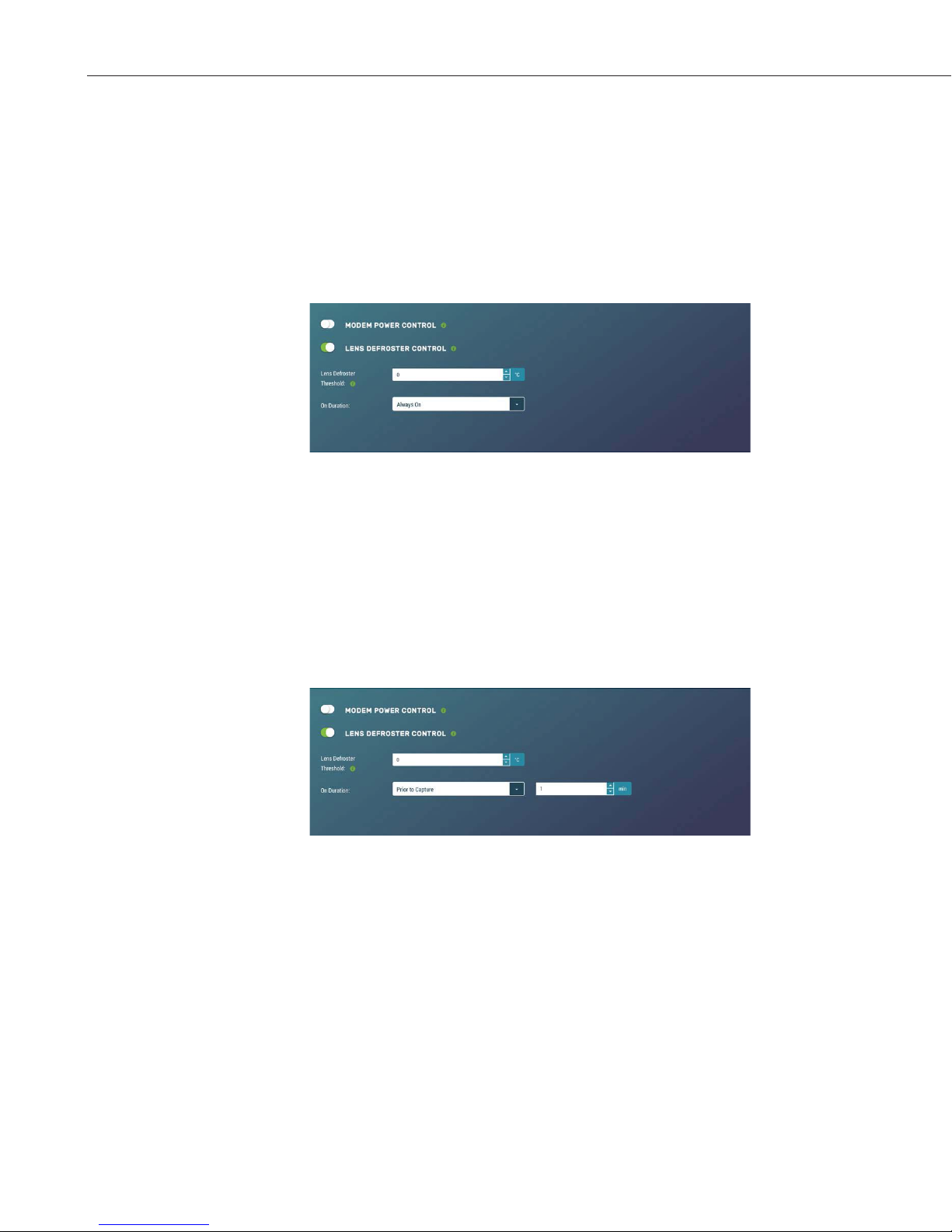
CCFC Field Camera
12.8.4.5.2 Lens Defroster Control
The Lens Defroster Control controls the operation of the lens defroster. When
enabled, the camera only turns on the lens defroster if the internal temperature
is below the threshold setting. The temperature threshold values are limited
between -40°C and +25°C.
If Always On is selected, the heater will be on whenever the temperature is
below the threshold and the camera is not in a low power state.
Figure 12-44 Lens Defroster Control: Always On
If Prior to Capture is selected, the camera will wake up prior to any of the
Timed Capture schedules and turn on the heater, if the temperature is below the
threshold settings. This feature does not work in Motion Detect or External
Trigger modes.
This is useful for a remote site that may be prone to riming and frost. A camera
that is setup to take hourly pictures can be configured to turn on the defroster
several minutes prior to the scheduled picture to defrost the lens using the
Prior to Capture drop down option and inputting a value in minutes.
Figure 12-45 Lens Defroster Control: Prior to Capture
68
Page 79

12.8.5 Advanced
12.8.5.1 GPS
CCFC Field Camera
Photos created by the CCFC can be geotagged - GPS coordinates can be
embedded in the photo files metadata.
Figure 12-46 GPS
Options for GPS Settings are: Degrees, Minutes, Seconds or Decimal Degrees.
When Degrees, Minutes, Seconds is selected, Latitude (North or South) and
Longitude (East and West) must be selected from the drop down and numerical
values for degrees, minutes, and seconds must be inputted.
Figure 12-47 GPS: Degrees, Minutes, Seconds
When Decimal Degrees is selected, Latitude (-90.0000 to 90.0000) and
Longitude (-180.0000 to 180.0000) values are inputted.
69
Page 80

CCFC Field Camera
Table 12-27 Import/Export Settings
Variable
Upload
Configuration
File
Choose file
Uploads selected file
. This file can be
found on the Campbell Scientific website
http://
Update IP address
settings
Checkbox
If selected, it updates IP address information from the
file.
Not selecting this will not update the IP address
information. This is useful
having two cameras with
the same IP
Fi
settings
Checkbox
If selected, it u
Not selecting this will not change the Wi
12.8.5.2 Import/Export
Figure 12-48 GPS: Decimal Degrees
The Import/Export tool is used to maintain continuity between cameras. It has
the ability to import and export settings to and from the CCFC camera.
Additionally, Import/Export allows for configuration settings to be uploaded or
downloaded via the web interface. The .xml configuration files are also
compatible with the Device Configuration Utility.
Figure 12-49 Import/Export Camera Settings
70
Options Description
from the computer
www.campbellsci.ca/ccfc
, as
address is not desirable.
Update Wi-
pdates Wi-Fi settings from file.
-Fi settings.
Page 81

CCFC Field Camera
Update PakBus
network settings
If selected, it updates the PakBus settings (see Section
12.8.3.3
PakBus).
Not selecting this will not update the PakBus settings.
This is useful
, as
having two cameras with the same IP
address is not desirable.
Button
Send the file with the selected update settin
camer
It may be necessary to reconnect to the camera if
network settings were changed.
Download
Configuration
File
Download Button
Downloads the configuration file to the connected
device.
Downloading the
setting up multiple cameras with the same function. The
option to download the configuration file allows easy
transfer of data from one camera to the other without
having to duplicate work.
Save
Configuration
File to
Internal
Memory
Saves the Configuration file to the camera memory.
Saving configuration files to camera memory can be
useful for keeping a record of previous configuration
versions.
Checkbox
gs to the
Upload
a and changes will be applied.
configuration file is useful when
Save Button
12.8.5.3 Update
Update provides the ability to update the firmware in the camera. It is
recommended to regularily check for firmware updates on the Campbell
Scientific website https://www.campbellsci.ca/downloads to ensure that the
camera has the most recent version of firmware.
Figure 12-50: Update
Once a file is downloaded, click on the Browse button to select the new
firmware update with the tar.gz file extension. Once the proper file is selected,
click on the Upload button and the process begins.
71
Page 82

CCFC Field Camera
Warning
Note
12.8.5.4 Users
During the update process DO NOT
disconnect power, close web browser, or
navigate away from the Update page. Once
the update is downloaded, unzip the .tar.gz
file and save to the desired location. DO NOT
uncompress the .tar.gz file; send as is to
camera.
Once the firmware update process is completed, the Dashboard will be
displayed indicating that the process is complete. The camera will reboot itself.
It will take a few minutes for the camera to operate normally. If connecting to
the camera via Ethernet, the web interface will automatically refresh when the
camera is up and running again. If connected to the camera via Wi-Fi, the
connection will need to be reestablished before connecting to the camera by
refreshing the browser.
The firmware update process normally keeps all configuration settings in the
camera. However, it is recommended to verify the settings after an update.
The first user added will always have admin permissions.
Users allows users, with various access levels, to be added to the camera.
Users enables a security login feature, which requires a user name and
password authentication. Without this activated, the camera is open to the
Internet. A total of 10 users can be added to the CCFC.
By default, cameras are shipped with the security authentication disabled.
When Authentication is set to Enable, users will be prompted for a User Name
and Password befor e access is given. Ensure that a record of user names and
passwords are kept. In the event that this information is lost and access to the
camera is no longer possible, the settings can be viewed or changed by
connecting the camera to a computer with the Device Configuration Utility,
using the RS-232 or RS-485 port, depending on the CCFC model that was
ordered.
72
Figure 12-51 Users and Security Settings
Page 83

Table 12-28 Users
Variable
Toggle, Drop
or
Enable
Used to enable a username/password security level when first
logging in to use the CCFC
.
User Name
4
– 32 characters in length. Used to log into the web
interface.
Access Level
Full camera access.
security. First user is automatically Admin.
Operator
Full camera access. Only restriction is
managing
Users and
Security
Settings.
Only have access to the Dashboard and read-only access to
the
File Explorer. Cannot change settings.
Password
Confirm
Password
Must be identical to the password
Note
Down,
Text
Toggle
Text
CCFC Field Camera
Description
12.8.5.5 History
Admin
Can create and edit users to disable
Viewer
Text 4 – 32 characters in length. Used to log into the interface.
Text
.
If a user needs to be removed from the User List, this must be done by a user with
Admin access. Remember that any deletion or changes will only be saved when the
Save button is selected.
Logged in user access level is displayed beside the Logout
navigation option.
The History page provides a log of system events. One of the most common
recorded events is the indication that the camera is correctly powered. The
message confirms that the camera memory is functioning and it also indicates
the size of the camera memory.
Other types of event messages and log files include:
x The camera memory or the allocated memory is full (when fill and stop
x Communication and file transfer errors that include:
memo ry man age m e n t is us e d).
o FTP
o Email
o PakBus
73
Page 84

CCFC Field Camera
Figure 12-52 History
13. RS-232 Communications
The RS-232 serial communications are used with the camera for two purposes:
to configure and setup the camera using Device Configuration Utility software
that Campbell Scientific provides and to send photo files from the camera to
other devices using the PakBus protocol.
This value is displayed on the web interface under Settings>File
Transfer>PakBus.
Figure 13-1 PakBus Settings
The CCFC Power I/O port is configured by default to provide a 3-wire RS-232
connection (Tx, Rx, Ground), as well as power. The wires can be terminated
directly on the control ports of a compatible datalogger. For connection to a
computer’s 9 pin serial port, use the L28840 DB9 FEMALE to Terminal Block
Adaptor, which facilitates the connection of the cable pigtail end to a computer
9-pin serial port. The adaptor is included with the CCFC.
74
Page 85

CCFC Field Camera
Table
Wire Colour
Function
Connection Required
Red Power
9 to 30 Vdc
Black
Shield
Pin 5 and Power Ground
White
Rx (input)
Pin 3
Green
Tx (output)
Pin 2
Table
Wire Colour
Function
Connection Required
Red Power
12 V Black
Shield
Datalogger G (Ground)
White
Rx (input)
Control Port Tx
Green
Tx (output)
Control Port Rx
Blue Ext Trigger
Control Port (optional)
Yellow
Switched PWR
Do no connect
Figure 13-2 L28840 DB9 FEMALE to Terminal Block Adapter
13-1 CCFC Connections to RS-232 Port
The required RS-232 connections to a datalogger are shown in Table 13-2.
13-2 Datalogger Connections to RS-232 Port
75
Page 86

CCFC Field Camera
14. RS-485 Communications
The optional RS-485 communication interface of the CCFC can be used in
conjunction with the MD485 to interface a datalogger to one or more cameras.
Refer to the MD485 Manual for additional information.
This value is displayed on the web interface under Settings>File
Transfer>PakBus.
The MD485 is useful for connecting more than one camera to a datalogger or if
long cable lengths are involved. If multiple cameras are connected to an
MD485, it would be beneficial to offset the capture times of the photos so that
only one camera is attempting to transmit a file at any given time.
The camera can download photos or video via an RS-485 port using the
PakBus protocol. An MD485 is required to interface the camera to a
datalogger. The following items are required for RS-485 PakBus
communications and can be confirmed by either the web interface of the
Device Configuration Utility:
x Confirm that the PakBus port parameter of the Communications
Setting is reading RS-485.
x Set the RS-485 BAUD rate to match the BAUD rate of the device
being connected to the camera.
x Set the parameter PakBus Address of Communication Settings to a
unique value in the PakBus network.
x Set the parameter PakBus Destination Address of the device that the
camera needs to send photos to.
x Include PakBus Security Code, as required.
15. Send Via PakBus: PakBus Communications
The CCFC camera uses the PakBus protocol to send photo or video files from
the camera to a Campbell Scientific datalogger or other PakBus compatible
devices. The Loggernet Tool PakBus Graph can be used to change the
configuration of a camera. The use of the PakBus Graph is discussed in Section
15.2 Send Via PakBus: PakBus Graph Operations. Refer to the Loggernet
literature or software for more details.
PakBus can also be used to control specific operational parameters and to
transfer variables or text between the datalogger and camera. When a photo or
video file is ready to be transmitted, the camera will initiate communications
and send the photo or video via the selected serial interface.
The CCFC is capable of producing video files that exceed 30MB. Trying to
send such a large file to a datalogger using PakBus can be problematic. For this
reason, the CCFC is setup to not send any files using PakBus that are larger
than 2MB.
76
Page 87

CCFC Field Camera
The camera is a PakBus Leaf node and is not capable of performing any
routing. However, the CCFC has the ability to communicate with devices that
are several hops away on the PakBus network.
15.1 Send Via PakBus: Concurrent PakBus Communications
PakBus allows the camera to download photos to a datalogger simultaneously
with other datalogger communications. A communications task will take longer
if the datalogger is communicating with multiple devices at the same time.
It is beneficial to set the system timing up to avoid photo transfers when other
communications are scheduled.
For example, longer connect times on long distance telephone connections can
be avoided by scheduling photo transfers from the camera to the datalogger
outside the scheduled data collection time. If a station is called on the hour to
retrieve data, photo acquisitions could be initiated before the scheduled call (15
minutes prior) to shorten the connect times.
15.2 Send Via PakBus: PakBus Graph Operations
The CCFC supports configuration via PakBus Graph over the serial port. A
datalogger or other type of PakBus relay device is required to interface PakBus
Graph to the camera.
15.2.1 Dataogger Settings
The datalogger must be configured as a router (i.e. Is Router must be set to
true) and the camera PakBus address must be in the list of allowed neighbours
for the datalogger port used. The camera and the datalogger must be set to use
the same baud rate to communicate properly.
15.2.2 Discovery
After starting the PakBus graph, the camera may not be visible immediately.
To discover the camera, right click on the green box marked as [4094] in the
graph and click on Search for Neighbours. This will open the Search for
Neighbours dialog box, press the Start button and the graph should display all
the devices within the PakBus network.
15.3 Setting Up Datalogger to Work with CCFC: PakBus
Variable Control
The camera is capable of receiving variables, commands, or text from a
datalogger. The specific operational parameters that can be altered or
controlled include:
x File Captions
x Camera Window Defroster
x Camera Shutdown
x GPS Coordinates
The use of the Send Variable instruction allows the datalogger to transfer
values or text that can be used in the photo or video banners. The Send
77
Page 88

CCFC Field Camera
Variable instruction is also used to toggle the camera window defroster on/off,
or safely shut the camera down.
To update the File Caption information with values from a datalogger the
variable is a String and must be limited to 255 characters (including null
terminator).
The camera variable names are:
x CCFCStillBanner1
x CCFCStillBanner2
x CCFCVideoBanner1
x CCFCVideoBanner2
The variable for controlling the window defroster is numeric and needs to be
declared as a Long in CRBasic. Sending any true or non-zero value will
activate both of these functions. The variable for controlling camera power is a
Boolean, which needs to be declared in CRBasic. The names of the camera
variables are:
x CCFCDefroster
x CCFCShutdown
Two PakBus variables allow the datalogger to send the GPS coordinates to the
camera where they are embedded in the media file metadata.
x CCFCGPSLatitude
x CCFCGPSLongitude
The GPS coordinates must be sent as floating point values. Positive latitude
and longitude represent northern and eastern hemispheres, respectively. While
negative values represent southern and western hemispheres, respectively.
Values are not saved through a power cycle or in Off Mode, but do need to be
updated every time a photo is sent. When using PakBus variables for GPS,
coordinates must be entered in decimal coordinates.
15.3.1 PakBus Control of Window Defroster Function
PakBus will temporarily (one shot) override the existing window defroster
control state. Users are advised to only use one type of control to avoid
unexpected operation of the defroster. Options include the Automatic Mode set
via the web interface, Device Configuration Utility, or the PakBus Send
Variables command.
To turn on the defroster, the numeric value should be set to a non-zero value
(i.e. 1). When a non-zero value is sent to the camera, the heater will turn on and
a 65 second countdown timer will start. After 65 seconds, the defroster will
automatically turn off (this should override settings already in place). If an
additional non-zero is sent before the defroster is turned off, then the timer will
be reset and will begin the countdown again from 65. Sending a zero value
using this variable will not turn off the defroster regardless of which method
was used to turn it on.
78
Page 89

CCFC Field Camera
Note
The defroster commands should be sent to the camera every 60 seconds or less
to ensure continuous operation.
The defroster will not be allowed to turn on at internal temperatures about
+25°C.
15.3.2 PakBus Control of CCFC Power
The ability to shut the camera down safely using a PakBus command is
available in the CCFC. By writing a value of 1 (or any value not equaling zero)
to the public Boolean variable CCFCShutdown the camera initiates a shutdown
and power down cleanly. The shutdown process can take up to 30 seconds. The
camera will turn back on after 10 minutes or can be externally triggered.
Following is an example of the CRBasic command that will shut down a
camera with PakBus address 55:
SendVariables (SendVarResult,Com1,0,55,0000,400, “Public”, “CCFCShutdown”,1,1)
15.3.3 Example Program – SendVariable Instruction – CR1000
The following example illustrates the use of the SendVariable instruction to
alter Still Photo Banner #2, as well as toggle the camera window defroster.
Please download the program directly from:
http://www.campbellsci.ca/ccfc.
'CR1000 Series Datalogger
'Declare Public Variables
Public PTemp, batt_volt
Public TurnDefrosterOn As Boolean
Public TurnDefrosterVal As Long
Public SendVarResult As Long
Public BannerString As String * 60
Public tempstring As String * 60
'Define Data Tables
DataTable (Test,1,-1)
DataInterval (0,60,Sec,10)
Minimum (1,batt_volt,FP2,0,False)
Sample (1,PTemp,FP2)
EndTable
'Main Program
BeginProg
SerialOpen (Com1,115200,4,0,2000)
Scan (10,Sec,0,0)
PanelTemp (PTemp,250)
Battery (batt_volt)
'Enter other measurement instructions
tempstring = FormatFloat(PTemp,"%2.2f")
BannerString = "Panel Temp " + tempstring
79
Page 90

CCFC Field Camera
Note
If TimeIntoInterval (0,5,Min) Then
SendVariables(SendVarResult,Com1,0,55,0000,400,"Public","CCFCStillBanner2",BannerString,1)
EndIf
If TurnDefrosterOn = true Then
TurnDefrosterVal = 1
SendVariables(SendVarResult,Com1,0,55,0000,200,"Public","CCFCDefroster",TurnDefrosterVal,1)
TurnDefrosterOn = false
EndIf
CallTable Test
NextScan
EndProg
15.3.4 Example Program – Adding GPS Coordinates to the Photo Banner –
CR1000
The following example illustrates the use of the CCFCGPSLatitude and
CCFCGPSLongitude instructions, which can be used with CR800 series,
CR1000, or CR3000 dataloggers.
Please download the program directly from:
http://www.campbellsci.ca/ccfc.
'CR1000 Series Datalogger
'Declare Public Variables
Public sendGps As Boolean
Public gpsLat, gpsLong As Float
Public sendVarResult
'Main Program
BeginProg
sendGps = false
gpsLat = 50.0
gpsLong = -139.0
SerialOpen (Com1,115200,4,0,2000)
Scan (1,Sec,0,0)
If sendGps Then
sendGps = false
SendVariables(sendVarResult,Com1,0,55,0000,0,"Public","CCFCGPSLatitude",gpsLat,1)
SendVariables (sendVarResult,Com1,0,55,0000,0,"Public","CCFCGPSLongitude",gpsLong,1)
EndIf
NextScan
EndProg
80
Page 91

15.4 PakBus Neighbouring Address
The PakBus protocol allows devices to relay data in a network. The CCFC has
the ability to communicate with devices that are several hops away on the
PakBus network. To configure this new feature, a setting has been added to the
PakBus configuration screen on the web page.
Physically entering the address of the PakBus device connected to the CCFC
PakBus communication lines allows the neighbor to relay communication
between the CCFC and the final destination for data. Leave PakBus set to zero
(0) if the CCFC is directly connected to the final destination.
16. Power Calculations and Timings
The CCFC was specifically designed for operation in power-contrained
systems such as solar powered sites. It is critical in such systems that the
camera be properly configured to meet the constraints of the intended
application. This section outlines the power consumption of the camera for
purposes of power supply design for a system.
16.1 Standalone Operation
CCFC Field Camera
In standalone mode, the camera operates as a self-contained photo and video
recorder. Files will be stored onto the internal camera memory.
The current draw of the camera is mainly dictated by the quiescent current
draw of the Power Mode, plus the current draw when the camera enters the
Fully On power mode (Active Current Draw) to acquire a photo or video.
Table 16-1 shows some total power consumption (standalone) figures in AmpHours per day depending on the Power Mode and frequency of photos.
One thing to note is that the Off State will only consume less power than the
Deep Sleep state if fewer than 24 pictures are taken per day. This is due to the
boot-up time that the camera requires when exiting the Off State. The extra
boot-up time means that the camera consumes the Active Current for a longer
time (120 seconds).
81
Page 92

CCFC Field Camera
Power
Mode
Ethernet
Power Save
Quiescent
Ethernet
Current Draw
Vdc
Active Current
Ethernet Draw
Max.@12Vdc
Active Duration
Hr
Per Day
1 JPG/Hr
Hr
Per Day
1 JPG/Hr
Amp-Hr Per
6 JPG/Hr
Fully On
Always On
Full Power
Save Mode
Partially
Always On
Full Power
Save Mode
Deep
Sleep
Always On
Full Power
Save Mode
Off State
Always On
Full Power
Save Mode
Note
On
Mode
Max.@12
250 mA 250 mA
0 Sec/JPG
200 mA 200 mA
0 Sec/JPG
90 mA 250 mA
0 Sec/JPG
10 mA 200 mA
0 Sec/JPG
6 mA 250 mA
0 Sec/JPG
6 mA 200 mA
0 Sec/JPG
1 mA 250 mA
0 Sec/JPG
1 mA 200 mA
0 Sec/JPG
Amp-
6.0 6.0 6.0
4.8 4.8 4.8
2.2 2.2 2.4
0.24
0.15
0.15
0.032
0.031
Amp-
0.28
0.19
0.18
0.22
0.18
Day
0.47
0.44
0.53
2.0
1.6
When the Wi-Fi is powered up and connected via an Access Point
(AP) or connected to an Existing Network (see Section 12.8.2
Network), an extra 40 mA is added to the current power draw.
When the camera is transmitting large amounts of data (e.g. when
viewing live video), an extra 10 mA is added to the power draw.
16.2 Operation with Communications
The power calculations are more complicated when communications are
involved, as the amount of time the camera is in the Fully On active state is
increased by the amount of time it takes for the camera to transfer a photo or
video.
The transfer times are influenced by two main factors: the size of the photo or
video and the transfer speed used to send the file. The amount of time the
camera is on will be increased as the size of the file becomes larger or as the
communication rate slows down.
To properly determine the power consumption when using communications,
the additional time the camera consumes the Fully On current draw needs to be
accounted for in the power calculation. Refer to Table 16-2 as a guideline for
determining the amount of time it takes to transfer files using RS-232 or RS485 PakBus communications.
82
Page 93

CCFC Field Camera
Table 16-1 File Transfer Times Using PakBus
Communication
BAUD RATE
9600
19200
38400
57600
115200
Time (seconds)
per 100Kbytes
240 seconds
0.0123 A-Hrs
120 seconds
0.0076 A-Hrs
60 seconds
0.0054 A-Hrs
40 seconds
0.0044 A-Hrs
30 seconds
0.0038 A-Hrs
To estimate the power consumption of the system, look up the parameters in
Table 16-1, along with the communication times to calculate the power
consumption as follows:
x Determine the Active Time in minutes:
Active Minutes = Number of pictures per day * (Active Duration +
Communication Time)/60
For a camera in the Deep Sleep state sending 24 photos per day at
115200 BAUD that are 100 Kbytes in size:
Active Minutes =24*(25 seconds + 30 seconds)/60 = 22 minutes/day
of Active Time
x Determine the total time in Quiescent Low Powered State
Quiescent minutes = 1440 minutes per day – Active minutes
Quiescent minutes = 1440 – 22 = 1418 minutes
x Determine the power consumed by the Quiescent state in Amp-Hours.
Quiescent power = Quiescent minutes * Quiescent Current Draw/60
Quiescent power = 1418 minutes*6 mA/60 = 141.8 mA- Hour or
0.1418 Amp-Hours/Day
x Determine the power consumed by the Active state in Amp-Hours.
Active power = Acti ve mi nutes * Active Curre nt Draw/60
Active power = 22 minutes*250 mA/60 = 91.67 mA-Hour or 0.0917
Amp-Hours/Day
83
Page 94

CCFC Field Camera
Table 17-1 CCFC Compatibility with Contemporary and Retired
Dataloggers
x Total power consumption is the sum of the Active and Quiescent
Power
Total power = Quiescent Power + Active Power
Total power = 0.1418 Amp-Hours/Day + 0.0917 Amp-Hours/Day
Total power = 0.2335 Amp-Hours/Day
17. CCFC Compatability
As shown in Table 17-1 CCFC Compatibility with Contemporary and Retired
Dataloggers, The CCFC is compatible with several contemporary and retired
Campbell Scientific dataloggers.
Contemporary Dataloggers Retired Dataloggers
CR200/200X CR510*
CR800/CR850 CR23X
CR300 CR10X*
*
CR1000
CR3000
CR6
*
Must be the -2M versions and must use the PakBus operating system.
18. CR1000 Interface Guide
The CCFC can interface to the CR1000 using the RS-232 (default) or RS-485.
The RS-232 configuration is the simplest option as it does not require an
additional hardware interface (see Section 13 RS-232 Communications). The
pigtail end of the CCFC Power & I/O cable can be terminated directly to the
CR1000 wiring panel control ports (COM1-4). Refer to Section 8
Cables/Wiring for wiring details.
The CCFC RS-485 interface can also be used, but does require the use of an
MD485 interface to provide conversion of the RS-485 signal (see Section 14
RS-485 Communications). The MD485 can connect to the CR1000 using the
CS I/O port or the RS-232 port. Refer to the MD485 manual for additional
information.
18.1 CR1000 Memory Setup
To facilitate the storage of photos, a CFM100 allows the use of a compact flash
card on the CR1000. Memory can also be allocated from the CR1000 internal
memory to create a virtual user drive – USR. Entering a non-zero value for the
parameter USR:drive size allocates internal memory for the drive. The amount
of memory required varies depending on each application. A good number to
84
Page 95

Note
start with is approximately 1048 Kbytes, which is 25% of the 4M bytes
available on a standard CR1000.
The following methods can be used to set the drive size of the USR:
x The Device Configuration Utility
x PakBus Graph
x Editing the parameter from the Status Table
x CR1000 optional keypad and display
The CCFC will not send any files using the PakBus that are greater
than 2 MB.
18.2 CR1000 Files Manager
The Files Manager setting on the CR1000 facilitates the management of jpeg
and avi files that are received from the camera. Files Manager allows the user
to specify a name for the files and the number of files kept in a ring memory
type fashion.
CCFC Field Camera
The format of the Files Manager setting is as follows:
x (AAAA,DDD:NAME.EXT,NNNN)
x AAAA – camera PakBus address.
x DDD – destination drive on the CR1000
USR for the user drive.
CRD for the compact flash memory card.
x NAME – any name string that will be used to name the files.
x EXT – the file extension of the incoming file must match. In the case
od the camera, this must always be either jpg or avi.
x NNNN – number of files kept in the memory ring. This number must
be low enough so that the memory required for files is less than what
is available in the corresponding drive. Otherwise, the USR memory
will not ring, but will fill up and stop. For the internal USR drive of a
datalogger this would normally be between 3 and 10 photos and for an
external memory card (i.e. CRD drive) the number of photos can be
larger. When communicating to retrieve photos, it is suggested to limit
the number of files in the ring memory to 200 in order to avoid long
communication delays.
Following is an example of Files Manager settings:
(55,USR:SkySouth.JPG,3)
x Camera PakBus address is 55
x The files will be stored in the USR: director with a name
SkySouth####.jpg where #### is an incrementing number. Entering a
zero for this parameter will disable the automatic numbering and
produce a fixed file name.
x The 3 most recent files will be kept. A new incoming file will cause
the oldest to be deleted.
85
Page 96

CCFC Field Camera
18.3 CR1000 COM Port (Control Port) Communications
On the CR1000, a pair of control ports can be configured to function as RS-232
communication (COM) ports. Any of these 4 COM ports can be configured as
PakBus ports and used to communicate with the camera.
The COM ports can be activated as PakBus ports using the Device
Configuration Utility or by using the SerialOpen instruction in the CR1000
program.
The following SerialOpen instruction configures COM Port 2.
x BAUD rate - 115200
x PakBus Port – 4
x Transmit delay – 0
x Buffer size – 1000
x SerialOpen(Com2,115200,4,0,1000)
19. Remote Photo Retrieval
Once the camera has transferred a photo or video to a datalogger, existing
LoggerNet communications can be used to remotely retrieve the photos and
video from the datalogger memory.
There are also permanent links available in the CCFC web interface to
download the most recently captured photos or video files that have been saved
to the camera memory (see Section 7.3.1 Link to Most Recent Photo and
Video).
19.1 LoggerNet File Retrieval
LoggerNet (version 4.0 or newer) includes the File Retrieval setup that
facilitates the photo and video file retrieval from PakBus dataloggers (CR800
series, CR1000, and CR3000, CR300, CR6). The File Retrieval tab is located
in the Setup Screen as part of the datalogger configuration. Once configured,
File Retrieval is used to retrieve photos and video from a datalogger.
86
Page 97

Note
Setup Screen
File Retrieval
Figure 19-1 File Retrieval Setup Screen
CCFC Field Camera
Select the required Retrieval Mode for the application. The Follow Scheduled
Data Collection option uses the scheduled configuration in the Schedule tab. If
the New Schedule option is selected, the Base Date and Time, and Retrieval
Interval parameters need to be configured.
It is possible to configure the File Retrieval to delete files once retrieved from
the datalogger. If datalogger memory capacity is a concern, it is recommended
to use this feature.
To add a file retrieval process, start by selecting Add New under File Pattern.
Once added, the Edit File Pattern, Output Directory, and Max Files parameter
become available to fill out. Each File Pattern added will need to be
individually configured.
Under the Edit File Pattern parameter, it is necessary to select from the
directory location options in order to specify the photo or video to be retrieved.
By default, the jpg and avi names are a wild card (*), which means all jpg or
avi files in the specified directory will be retrieved. If specific file names in the
camera configuration have been used, those file names can be specified in the
Edit File Pattern parameter. It is possible to configure multiple File Patterns to
collect photos or video on different schedules or from multiple directories.
If LoggerNet File Retrieval does not list the avi files a s an op tion
under File Edit Pattern, force the filename and format.
The default Output Directory is C:\Campbellsci\LoggerNet. If required, the
preferred location can be found by browsing. The Max Files parameter
specifies the maximum number of files that can be retrieved during each
scheduled event. The newest files will be retrieved.
87
Page 98

CCFC Field Camera
File Control
19.2 Using LoggerNet File Control
When the Force Retrieval box is selected, a file that matches the file pattern
will be retrieved regardless of the file’s timestamp or whether the file has
already been retrieved. When the Record If Skipped box is selected, the names
and dates of any files that are not retrieved because of the Max Files parameter
will be recorded and they will not be retrieved later. If this box is not selected,
the skipped files can be retrieved in a later attempt.
Photos or video that are in the datalogger memory can be viewed or collected
on demand by using File Control that is available from the Connection Screen
menu. The use of File Control requires a communications connection to the
datalogger. Using the File Control can also be useful for debugging purposes.
88
Figure 19-2 Loggernet Connection Screen
In dataloggers such as the CR1000, the Device Map can include the CPU,
USR, and the CRD (compact flash module). The devices show up in the left
hand side of the File Control panel. To view files of a certain device, simply
click on the desired device listed in the panel (Figure 19-3 USR Drive View in
File Control). Use the Retrieve button to download the photo from the
datalogger.
Page 99

Figure 19-3 USR Drive View in File Control
CCFC Field Camera
20. Mounting
The camera enclosure is designed to be environmentally sealed for outdoor
installations. The enclosure provides protection from moisture or high
humidity. It is not intended for operation under water. All that is required is an
appropriate mounting fixture.
Figure 20-1 CCFC Mounting Kit
The camera is equipped with a set of three ¼-20 threaded mounting holes (see
Figure 20-2). These mounting holes are centered along the bottom of the camera
and are spaced 1.0” (25.4 mm) apart from one another. At least two of the ¼-20
threaded holes are required for mounting the camera.
89
Page 100

CCFC Field Camera
Crossarm
U-Bolt
¼-20 x 0.5”
Hex bolts
Figure 20-2 CCFC Mounting Holes
When using the optional Mounting Kit, align the outer holes of the CCFC with
the center hole and the 180° slot of the mount. Loosely secure the two together
with the two ¼-2 0 x 0.5” Hex bolts included with the kit. It is now possible to
mount the CCFC to either a crossarm or other mounting surface with the
included u-bolt.
With the hardware loose, the camera and the mount can be pivoted to allow a
full range of motion when aiming the camera. The hardware should be secured
once the camera is properly aimed at the intended target.
Figure 20-3 CCFC Mounted to Crossarm
90
 Loading...