

Page 1

BlackGlobe Temperature
Sensor for Heat Stress
Revision: 9/13
Campbell Scientific, Inc.
Copyright © 2013
Page 2

Page 3

Warranty
“PRODUCTS MANUFACTURED BY CAMPBELL SCIENTIFIC, INC. are
warranted by Campbell Scientific, Inc. (“Campbell”) to be free from defects in
materials and workmanship under normal use and service for twelve (12)
months from date of shipment unless otherwise specified in the corresponding
Campbell pricelist or product manual. Products not manufactured, but that are
re-sold by Campbell, are warranted only to the limits extended by the original
manufacturer. Batteries, fine-wire thermocouples, desiccant, and other
consumables have no warranty. Campbell’s obligation under this warranty is
limited to repairing or replacing (at Campbell’s option) defective products,
which shall be the sole and exclusive remedy under this warranty. The
customer shall assume all costs of removing, reinstalling, and shipping
defective products to Campbell. Campbell will return such products by surface
carrier prepaid within the continental United States of America. To all other
locations, Campbell will return such products best way CIP (Port of Entry)
INCOTERM® 2010, prepaid. This warranty shall not apply to any products
which have been subjected to modification, misuse, neglect, improper service,
accidents of nature, or shipping damage. This warranty is in lieu of all other
warranties, expressed or implied. The warranty for installation services
performed by Campbell such as programming to customer specifications,
electrical connections to products manufactured by Campbell, and product
specific training, is part of Campbell’s product warranty. CAMPBELL
EXPRESSLY DISCLAIMS AND EXCLUDES ANY IMPLIED
WARRANTIES OF MERCHANTABILITY OR FITNESS FOR A
PARTICULAR PURPOSE. Campbell is not liable for any special, indirect,
incidental, and/or consequential damages.”
Page 4

Assistance
Products may not be returned without prior authorization. The following
contact information is for US and international customers residing in countries
served by Campbell Scientific, Inc. directly. Affiliate companies handle
repairs for customers within their territories. Please visit
www.campbellsci.com to determine which Campbell Scientific company serves
your country.
To obtain a Returned Materials Authorization (RMA), contact CAMPBELL
SCIENTIFIC, INC., phone (435) 227-9000. After an applications engineer
determines the nature of the problem, an RMA number will be issued. Please
write this number clearly on the outside of the shipping container. Campbell
Scientific’s shipping address is:
CAMPBELL SCIENTIFIC, INC.
RMA#_____
815 West 1800 North
Logan, Utah 84321-1784
For all returns, the customer must fill out a “Statement of Product Cleanliness
and Decontamination” form and comply with the requirements specified in it.
The form is available from our web site at www.campbellsci.com/repair. A
completed form must be either emailed to repair@campbellsci.com or faxed to
(435) 227-9106. Campbell Scientific is unable to process any returns until we
receive this form. If the form is not received within three days of product
receipt or is incomplete, the product will be returned to the customer at the
customer’s expense. Campbell Scientific reserves the right to refuse service on
products that were exposed to contaminants that may cause health or safety
concerns for our employees.
Page 5

Table of Contents
PDF viewers: These page numbers refer to the printed version of this document. Use the
PDF reader bookmarks tab for links to specific sections.
1. Introduction.................................................................1
2. Cautionary Statements............................................... 1
3. Initial Inspection .........................................................1
3.1 Ships With List.....................................................................................1
4. Overview......................................................................2
5. Specifications .............................................................2
5.1 Accuracy ..............................................................................................2
6. Installation...................................................................4
6.1 Siting ....................................................................................................4
6.2 Assembly and Mounting ......................................................................4
6.2.1 Mounting the BlackGlobe on the Mounting Arm .........................4
6.2.2 Mounting the BlackGlobe Assembly on a Horizontal
Crossarm....................................................................................6
7. Operation.....................................................................7
7.1 Wiring ..................................................................................................7
7.2 Calculations..........................................................................................8
7.2.1 Wet-Bulb Globe Thermometer Index (WBGT)............................8
7.2.2 Dewpoint.......................................................................................8
7.2.3 Vapor Pressure ..............................................................................9
7.2.4 Saturated Vapor Pressure ..............................................................9
7.2.5 Wet-Bulb.......................................................................................9
7.2.6 Mean Site Barometric Pressure Calculation (SP_kPa)................10
7.3 Programming......................................................................................10
7.3.1 Example CR1000 Program .........................................................10
7.4 Long Lead Lengths ............................................................................12
8. Maintenance ..............................................................12
9. References ................................................................12
i
Page 6

Table of Contents
Appendices
The Theory of BlackGlobe Temperature and
A.
Heat Stress ............................................................A-1
B. Edlog Programming Examples ..............................B-1
B.1 Example CR10X Program............................................................... B-1
B.2 Edlog Programming for Long Lead Lengths................................... B-9
Figures
5-1. Polynomial error curve (Edlog dataloggers only)................................ 3
5-2. Thermistor interchangeability limits ................................................... 4
6-1. Mounting kit components.................................................................... 5
6-2. Nuts and lock washers on mounting bolt............................................. 5
6-3. BlackGlobe fitting and cable alignment .............................................. 6
6-4. BlackGlobe mounted to a crossarm (front view)................................. 7
6-5. BlackGlobe mounted to a crossarm (back view)................................. 7
Tables
5-1. Thermistor Interchangeability Specification ....................................... 3
5-2. Polynomial Error ................................................................................. 3
7-1. Wiring Diagram for Campbell Scientific Dataloggers ........................ 8
A-1. Sample use of WBGT Index............................................................ A-1
B-1. Polynomial Coefficients .................................................................. B-7
B-2. Actual Temperature, Sensor Resistance, and Computed
Temperature................................................................................. B-7
ii
Page 7

BlackGlobe Temperature Sensor for
Heat Stress
1. Introduction
The BlackGlobe Temperature Sensor for Heat Stress (BlackGlobe) measure
radiant temperature. This measurement, along with the measurement of
ambient air and wet-bulb temperatures, is used to calculate the wet-bulb globe
temperature (WBGT). The WBGT index combines the effects of temperature,
humidity, radiant heat, and wind into one single index employed to express
environmental heat stress. The measurement of heat stress is important
because loss of physical and mental efficiency occurs under definable degrees
of heat stress. Severe heat stress can lead to fatigue, exhaustion and possibly
even disability or death.
Before installing the BlackGlobe, please study
• Section 2, Cautionary Statements
• Section 3, Initial Inspection
2. Cautionary Statements
• The BlackGlobe is a precision instrument. Please handle it with care.
• The black outer jacket of the cable is Santoprene® rubber. This
compound was chosen for its resistance to temperature extremes, moisture,
and UV degradation. However, this jacket will support combustion in air.
It is rated as slow burning when tested according to U.L. 94 H.B. and will
pass FMVSS302. Local fire codes may preclude its use inside buildings.
• Do not use the BlackGlobe with long lead lengths in an electrically noisy
environment.
3. Initial Inspection
• Upon receipt of the BlackGlobe, inspect the packaging and contents for
damage. File damage claims with the shipping company. Immediately
check package contents against the shipping documentation (see Section
3.1, Ships With List). Contact Campbell Scientific about any
discrepancies.
• The model number and cable length are printed on a label at the
connection end of the cable. Check this information against the shipping
documents to ensure the expected product and cable length are received.
3.1 Ships With List
• (4) 7362 8 inch Wire Ties
• (1) 29956 BlackGlobe Mounting Kit
• ResourceDVD
1
Page 8

BlackGlobe Temperature Sensor for Heat Stress
4. Overview
The BlackGlobe uses a thermistor inside a 15.24 cm (6 in) hollow copper
sphere, painted black to measure radiant temperature. This measurement along
with the measurement of ambient air and wet-bulb temperatures may be used to
calculate the WBGT index, which is sometimes referred to as the Humidex.
Sensor cable length is specified at the time of order. Do not exceed 1000 feet
of cable.
To calculate the wet-bulb globe thermometer index (WBGT), the measurement
of the BlackGlobe (radiant heat), wet-bulb (evaporative heat), and ambient air
(dry-bulb) temperatures are required. The wet-bulb temperature can be
calculated using air temperature and relative humidity if a wet-bulb
thermometer is not available. See Section 7.2, Calculations.
5. Specifications
Temperature Measurement Range: –5° to +95°C
Temperature Survival Range: –50° to +100°C
NOTE
5.1 Accuracy
Thermistor Interchangeability Error: Typically < ±0.2°C over 0°C to 70°C
and ±0.3 at 95°C
Polynomial Linearization Error: < ±0.5°C over –7°C to +90°C
Near Normal Emittance: 0.957
Maximum Cable Length: 305 m (1000 ft)
The black outer jacket of the cable is Santoprene
compound was chosen for its resistance to temperature extremes,
moisture, and UV degradation. However, this jacket will support
combustion in air. It is rated as slow burning when tested
according to V.L. 94 H.B. and will pass FMVSS302. Local fire
codes may preclude its use inside buildings.
The overall probe accuracy is a combination of the thermistor’s
interchangeability specification, the precision of the bridge resistors, and the
Steinhart-Hart equation error (CRBasic dataloggers) or the polynomial error
(Edlog dataloggers). In a worst case, all errors add to an accuracy of ±0.3°C
over the range of –3° to 90°C and ±0.7°C over the range of –5° to 95°C. The
major error component is the interchangeability specification of the thermistor,
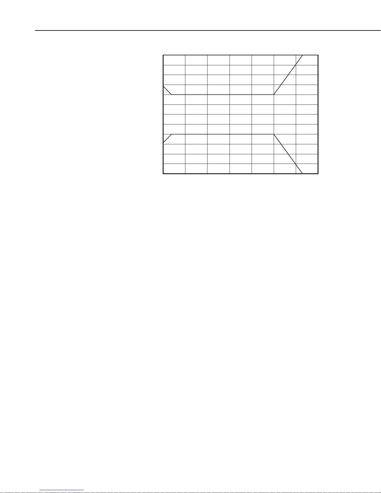
tabulated in TABLE 5-1 and plotted in FIGURE 5-2. For the range of 0° to
50°C, the interchangeability error is predominantly offset and can be
determined with a single point calibration. Compensation can then be done
with an offset entered in the measurement instruction. The bridge resistors are
0.1% tolerance with a 10 ppm temperature coefficient. Polynomial errors are
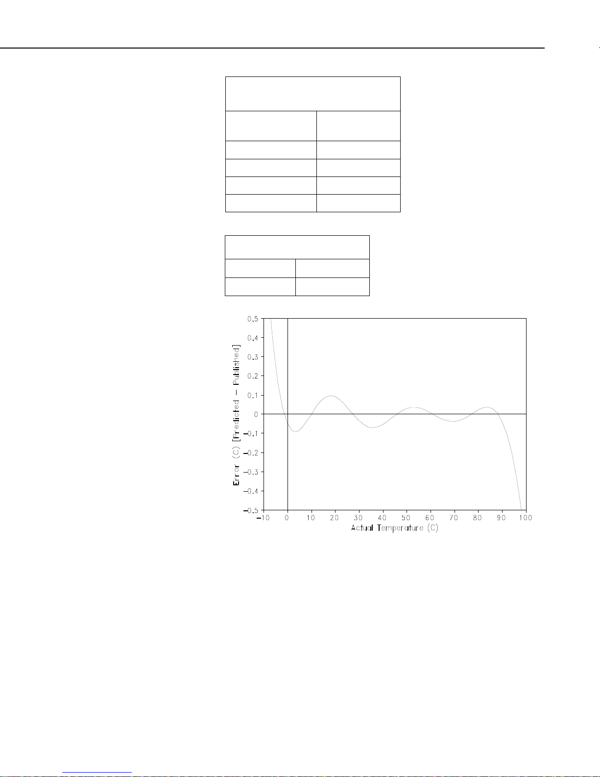
tabulated in TABLE 5-2 and plotted in FIGURE 5-1.
@
rubber. This
2
Page 9
BlackGlobe Temperature Sensor for Heat Stress
TABLE 5-1. Thermistor
Interchangeability Specification
Temperature (°C)
−5
Temperature
Tolerance (±°C)
0.14
0 to +70 0.10
+85 0.25
+95 0.35
TABLE 5-2. Polynomial Error
–5° to +95° < ±0.5°C
–3° to +90° < ±0.1°C
FIGURE 5-1. Polynomial error curve (Edlog dataloggers only)
3
Page 10
BlackGlobe Temperature Sensor for Heat Stress
6. Installation
Thermistor Interchangeability Limits
0.3
0.25
0.2
0.15
0.1
T
error
T
error
_therm_pos
_therm_neg
0.05
0
-0.05
-0.1
-0.15
-0.2
-0.25
-0.3
-5 10 25 40 55 70 85 100
T
FIGURE 5-2. Thermistor interchangeability limits
6.1 Siting
The BlackGlobe must be mounted in a location that will not be shadowed and
is representative of the environmental conditions to be measured.
6.2 Assembly and Mounting
Tools required for installing on a tripod or tower:
• Adjustable end wrench or 7/16 in. and 1/2 in. open end wrench
• Small screwdriver provided with the datalogger
• Small pair of diagonal-cutting pliers
• UV resistant cable ties provided with the BlackGlobe
6.2.1 Mounting the BlackGlobe on the Mounting Arm
The BlackGlobe and mounting kit (pn 29956) requires some assembly before
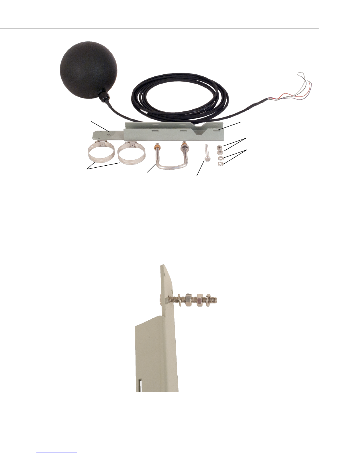
installation. The mounting kit comes with (see Figure 6.1):
• Mounting arm
• Mounting bolt
• Two lock washers
• Two nuts
• Two pipe clamps (not used when mounted to a horizontal pipe cross
arm)
• U-bolt with associated nuts and washers
4
Page 11
BlackGlobe Temperature Sensor for Heat Stress
m
N
t
Mounting Ar
Pipe Clamps
Pipe Clamp Slot
uts
Lock Washers
U-bolt
Mounting Bol
FIGURE 6-1. Mounting kit components
1. Place the mounting bolt through the hole in the mounting arm as shown in
FIGURE 6-2.
2. Slide one of the lock washers against the mounting arm.
3. Thread both nuts about half way down the bolt and then slide on the last
lock washer. The hardware should be arranged as shown in FIGURE 6-2.
FIGURE 6-2. Nuts and lock washers on mounting bolt
5
Page 12

BlackGlobe Temperature Sensor for Heat Stress
4. Tighten down the nut closest to the mounting arm so the bolt is held firmly
in place.
5. Thread the BlackGlobe fitting onto the bolt. Thread it as far down as it
will go, but you may have to back it off a bit. The cable gland and cable
should align with the mounting arm as shown in FIGURE 6-3.
6. Tighten down the nut closest to the BlackGlobe fitting. The BlackGlobe
and mounting bolt should not move when the all the hardware is tightened
down.
Cable Gland
FIGURE 6-3. BlackGlobe fitting and cable alignment
6.2.2 Mounting the BlackGlobe Assembly on a Horizontal Crossarm
The BlackGlobe assembly must be mounted on a horizontal crossarm.
1. Position the sensor so that the cable gland is facing down (FIGURE 6-3).
2. Use the mounting hardware supplied to hold the sensor on the horizontal
crossarm. FIGURE 6-4 and FIGURE 6-5 show a BlackGlobe mounted on
a crossarm by using the U-bolts.
3. Use the wire ties provided with the unit to secure the cabling to the
crossarm.
4. Leave a small loop of cable at the cable entry into the sensor to act as a
drip line for any condensed moisture or rain (FIGURE 6-4).
6
Page 13

BlackGlobe Temperature Sensor for Heat Stress
FIGURE 6-4. BlackGlobe mounted to a crossarm (front view)
7. Operation
7.1 Wiring
FIGURE 6-5. BlackGlobe mounted to a crossarm (back view)
The wiring diagram for the BlackGlobe to a Campbell Scientific datalogger is
given in TABLE 7-1. Temperature is measured with one single-ended input
channel and a voltage excitation channel. Multiple probes can be connected to
the same excitation channel (the number of probes per excitation channel is
physically limited by the number lead wires that can be inserted into a single
voltage excitation terminal, approximately six).
7
Page 14

BlackGlobe Temperature Sensor for Heat Stress
TABLE 7-1. Wiring Diagram for Campbell Scientific Dataloggers
Color
Black Voltage
Description
Excitation
CR800
CR850
CR5000
CR3000
CR1000
CR9000(X)
Switched
Voltage
Excitation
Red Temperature
Signal
Purple Signal Ground
Clear Shield
Single-Ended
Input
7.2 Calculations
7.2.1 Wet-Bulb Globe Thermometer Index (WBGT)
To calculate the WBGT index, a measurement of the BlackGlobe (radiant
heat), wet-bulb (evaporative heat), and ambient air (dry-bulb) temperatures are
required (Equation 1). In the approach discussed here, air temperature and
relative humidity measurements are used to calculate the actual vapor pressure,
and a dewpoint temperature is used to calculate the wet-bulb temperature.
CR510
CR500
CR10(X)
Switched
Excitation
Single-Ended
Input
AG
G
21X
CR7
CR23X
Switched
Excitation
Single-Ended
Input
7.2.2 Dewpoint
Air temperature and relative humidity (%) measurements required for this
calculation can be made by a variety of sensors. In the examples shown in
Section 7.3, Programming, the HC2S3 is used.
Ultimately,
WBGT = (0.2 × BlackGlobe Temp) + (0.7 × Wet-Bulb Temp) + (0.1 × DryBulb Temp) (1)
Dewpoint and Wet-Bulb temperature units include: °C, °F, °K
Equation 2 is used to calculate dewpoint.
T
= (241.88*ln(P/0.61078))/(17.558-ln(P/0.61078)) (2)
d
where
T
= dewpoint (°C)
d
P = vapor pressure (kPa)
8
Page 15

The equation is an inverse of a version of Teten’s equation (Tetens, 1930),
optimized for dewpoints in the range –35° to 50°C, and is accurate to within
plus or minus 0.1°C within that range.
7.2.3 Vapor Pressure
Vapor pressure is calculated by the datalogger using Equation 3.
BlackGlobe Temperature Sensor for Heat Stress
P = RH*P
/100 (3)
sw
where
RH = relative humidity (%)
P
= saturation vapor pressure (kPa) over water
sw
7.2.4 Saturated Vapor Pressure
Saturation vapor pressure over water is calculated by the datalogger using
Equation 4.
(kPa) = 0.1*(6.107799961 + T(4.436518521 × 10⁻¹ + T(1.428945805 ×
P
sw
–2
+ T(2.650648471 × 10⁻⁴ + T(3.031240396 × 10⁻⁶ + T(2.034080948 × 10⁻⁸
10
+ 6.136820929 × 10
where
T = air temperature (dry-bulb temperature) (°C)
7.2.5 Wet-Bulb
Wet-bulb is derived using an iterative process. The wet-bulb temperature lies
somewhere between the dry-bulb temperature (air temperature) and the
dewpoint temperature. The datalogger uses Equation 5 to calculate vapor
pressure using the dry-bulb temperature and a wet-bulb temperature estimate:
–11
× T)))))) (4)
–(0.000660*(1+0.00115*Tw)*(T–Tw)*SP) (5)
P = P
w
where
P
= saturation vapor pressure (kPa) at the wet-bulb temperature (°C)
w
T
= wet-bulb temperature (°C)
w
T = air temperature (dry-bulb temperature) (°C)
SP = standard air pressure (kPa) at the user entered elevation
The resulting vapor pressure is compared to the true vapor pressure (see above)
and the difference determines the next wet-bulb temperature estimate. The
process repeats until the difference between the current wet-bulb temperature
estimate and the previous wet-bulb temperature estimate is only plus or minus
0.01°C. The datalogger thus derives the wet-bulb temperature.
9
Page 16

BlackGlobe Temperature Sensor for Heat Stress
(
7.2.6 Mean Site Barometric Pressure Calculation (SP_kPa)
The wet-bulb instruction needs mean barometric pressure which is closely
related to elevation of the site. U.S. Standard Atmosphere and dry air were
assumed when Equation 6 was derived (Wallace & Hobbes, 1977).
SP
kPa
25328.5
⎧
⎛
⎪
11325.101325.101
−−−=
⎜
⎨
⎝
⎪
⎩
E
69231.44307
⎫
⎞
⎪
⎟
⎠
(6)
⎬
⎪
⎭
The value of SP
is in kilopascals and the site elevation, E, is in meters.
kPa
Use Equation 7 to convert feet to meters.
)
()
mE
The value for SP
ftE
=
281.3
(7)
ft/m
must be put into the datalogger program.
kPa
7.3 Programming
7.3.1 Example CR1000 Program
The example includes measurements of the BlackGlobe temperature, and the
calculation of wet-bulb temperature and wet-bulb globe temperature.
Measurements of air temperature and relative humidity are supplied by an
HC2S3 in this example. Calculations for dewpoint, wet-bulb, and wet-bulb
globe temperature are also included.
'CR1000 Series Datalogger
'Program: BlackGlobe.CR1
'Declare constants
'Mean site barometric pressure at 1357.58 meters.
'CHANGE THIS VALUE TO MATCH YOUR ELEVATION.
Const SP_kPa = 86.04377
'Declare Public Variables
'Datalogger variables.
Public PnlTempC 'Datalogger panel temperature
Units PnlTempC=Deg C
Public Batt_Volt 'Datalogger battery voltage
Units Batt_Volt=VDC
'BlackGlobe variables.
Public BGTemp_C 'BlackGlobe temperature
Units BGTemp_C=Deg C
'Rotronic HC2S3 variables.
Public AirTempC 'Air temperature
Units AirTempC=Deg C
Public AirRH 'Humidity
Units AirRH=%
'Calculated variables.
Public DewPnt_C 'Dewpoint temperature
Public WetBlb_C 'Wet-bulb temperature
Public WBGT_C 'Wet-bulb globe (HUMIDEX) temperature
Dim SVP_kPa
Dim VP_kPa
10
Page 17

BlackGlobe Temperature Sensor for Heat Stress
Dim UpperTmp
Dim LowerTmp
Dim old_wbT, new_wbT
Dim WB_VP_kPa, Diff_VP_kPa
Dim Diff_wbT
'Define Data Tables
'Hourly data table.
DataTable (Hourly,1,-1)
DataInterval (0,1,Hr,10)
Average (1,AirTempC,FP2,False)
Sample (1,AirRH,FP2)
Average (1,DewPnt_C,FP2,False)
Average (1,WetBlb_C,FP2,False)
Average (1,WBGT_C,FP2,False)
EndTable
'Daily datalogger status table.
DataTable (Daily,True,-1)
DataInterval (0,1,Day,10)
Maximum (1,Batt_Volt,FP2,False,False)
Minimum (1,Batt_Volt,FP2,False,False)
Maximum (1,PnlTempC,FP2,False,False)
Minimum (1,PnlTempC,FP2,False,False)
EndTable
'Main Program
BeginProg
Scan (5,Sec,3,0)
PanelTemp (PnlTempC,250)
Battery (Batt_Volt)
'Rotronic HC2S3 powered up all the time.
VoltSe (AirTempC,1,mV2500,1,0,0,_60Hz,0.1,-40)
VoltSe (AirRH,1,mV2500,2,0,0,_60Hz,0.1,0)
If (AirRH >= 100) AND (AirRH <= 108) Then AirRH = 100
SatVP (SVP_kPa,AirTempC)
VP_kPa = SVP_kPa * AirRH/100
DewPoint (DewPnt_C,AirTempC,AirRH)
If (DewPnt_C > AirTempC) Or (DewPnt_C = NAN) Then DewPnt_C = AirTempC
UpperTmp = AirTempC
LowerTmp = DewPnt_C
'BlackGlobe wired to SE channel 3 and excitation channel VX1.
Therm108 (BGTemp_C,1,3,Vx1,0,_60Hz,1.0,0)
'Loop to find wet-bulb temperature.
Do
old_wbT = new_wbT
new_wbT = ((UpperTmp - LowerTmp)/2) + LowerTmp
WetDryBulb (WB_VP_kPa,AirTempC,new_wbT,SP_kPa)
Diff_VP_kPa = WB_VP_kPa - VP_kPa
Diff_wbT = ABS (old_wbT - new_wbT)
If Diff_VP_kPa > 0 Then
UpperTmp = new_wbT
Else
LowerTmp = new_wbT
EndIf
If Diff_wbT < 0.01 Then ExitDo
Loop
'Wet-bulb temperature.
WetBlb_C = new_wbT
'Calculate Wet-Bulb Globe (HUMIDEX) temperature.
WBGT_C = (0.1 * AirTempC) + (0.2 * BGTemp_C) + (0.7 * WetBlb_C)
'Call data storage tables.
CallTable Hourly
CallTable Daily
NextScan
EndProg
11
Page 18

BlackGlobe Temperature Sensor for Heat Stress
7.4 Long Lead Lengths
If the BlackGlobe has lead lengths greater than 300 feet, a longer settling time
before the measurement is made is required. For CRBasic loggers, the 60 and
50 Hz integration options include a 3 ms settling time; longer settling times
also can be entered into the Settling Time parameter. In Edlog, use the DC
Half Bridge Instruction (Instruction 4) with a 2 ms delay to measure the
temperature.
CAUTION
Do not use the BlackGlobe with long lead lengths in an
electrically noisy environment.
8. Maintenance
The BlackGlobe requires minimal maintenance. Check monthly to ensure the
sphere is free from dirt and debris. Clean with water and soft cloth if
necessary. Do not use solvents as they may dissolve the paint.
9. References
Lowe, P.R. 1977. J. Appl. Meteor., 16:100-103
Tetens, O. 1930. Z. Geophys., 6:297
Wallace, J.M. and P.V. Hobbes, 1977: Atmospheric Science: An Introductory
Survey, Academic Press, pp. 59 – 61
12
Page 19

Appendix A. The Theory of BlackGlobe
Temperature and Heat Stress
The Wet-Bulb Globe Temperature Index (WBGT) combines the effects of
temperature, humidity, radiant heat, and wind into one single index employed
to express environmental heat stress. Loss of physical and mental efficiency
occurs under definable degrees of heat stress. Severe heat stress can lead to
fatigue, exhaustion and possibly even disability or death. Personnel can
increase their resistance to heat stress by acclimatizing gradually to hot
environments and by maintaining a good water and salt balance.
Heat stress can be reduced by decreasing the lengths of exposure and
decreasing the workload of individuals under heat stress. Situational factors
such as the type of clothing worn, the type of work performed, the
psychological effects of stress, and the availability of fluids can also affect the
assessment of heat stress. These factors are not easily quantified, and so the
individual in a given situation must estimate their significance. Environmental
factors such as temperature, humidity, and wind are more easily measured to
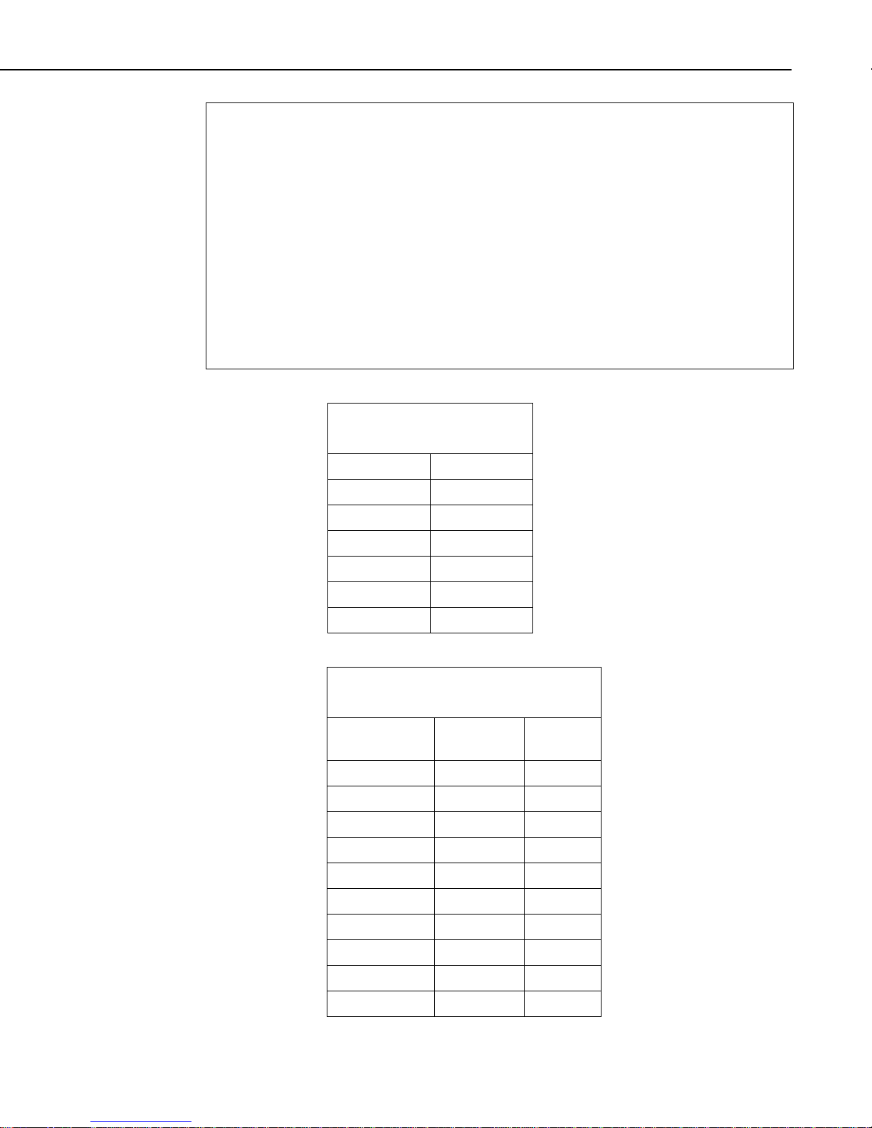
assess heat stress. TABLE A-1 provides some guidelines for using the WBGT
index.
TABLE A-1. Sample use of WBGT Index
Readings Guidelines
WBGT Index
Reading 26 – 27.5
WBGT Index
Reading 27.5 – 29
WBGT Index
Reading 29 – 31
WBGT Index
Reading 31 – 32
WBGT Index
Reading >32
Precautions should be taken. Water intake should be a
minimum of 0.5 liters/hr. The work/rest cycle for an
acclimatized person should be 50/10 min/hr.
Increased water intake should be emphasized. Water
intake should be 0.5 to 1 liters/hr. The work/rest cycle
for an acclimatized person should be 50/10 min/hr.
Increased supervision of personnel performing physical
activity is required. Water intake should be 1 to 1.5
liters /hr. The work/rest cycle for an acclimatized person
should be 45/15 min/hr.
Physical activity should be limited to a maximum of 6
hours per day for fully acclimatized personnel. Water
intake should be 1.5 to 2 liters/hr. The work/rest cycle
for an acclimatized person should be 30/30 min/hr.
All strenuous activity should be suspended. Water
intake should be a minimum of 2 liters/hr. The
work/rest cycle for an acclimatized person (nonstrenuous activity) should be 20/40 min/hr.
A-1
Page 20

Appendix A. The Theory of BlackGlobe Temperature and Heat Stress
A-2
Page 21

Appendix B. Edlog Programming
Examples
B.1 Example CR10X Program
Instruction 5 (AC Half Bridge) is used to measure the thermistor probe inside
the sphere. Instruction 55 (Polynomial) is used to calculate the temperature
in degrees Celsius. The polynomial coefficients are shown in TABLE B-1.
Thermistor resistance and computed temperature over a –10 to +84°C range is
shown in TABLE B-2. The example includes instructions for measuring an
HC2S3 to supply air temperature and relative humidity values. Calculations
for dewpoint, wet-bulb, and wet-bulb globe temperature are also included.
;{CR10X}
;Program: BLACKGLOBE.CSI
;Date: June 2013
*Table 1 Program
01: 5.0000 Execution Interval (seconds)
1: Batt Voltage (P10)
1: 1 Loc [ BattVolt ]
2: Internal Temperature (P17)
1: 2 Loc [ CR10XTmpC ]
;Rotronic HC2S3 temperature and relative humidity.
;Sensor powered on all the time.
3: Volt (SE) (P1)
1: 1 Reps
2: 5 2500 mV Slow Range
3: 1 SE Channel
4: 4 Loc [ AirTempC ]
5: 0.1 Multiplier
6: -40 Offset
4: Volt (SE) (P1)
1: 1 Reps
2: 5 2500 mV Slow Range
3: 2 SE Channel
4: 5 Loc [ AirRH ]
5: 0.1 Multiplier
6: 0 Offset
5: If (X<=>F) (P89)
1: 5 X Loc [ AirRH ]
2: 3 >=
3: 100 F
4: 30 Then Do
B-1
Page 22

Appendix B. Edlog Programming Examples
6: If (X<=>F) (P89)
1: 5 X Loc [ AirRH ]
2: 4 <
3: 108 F
4: 30 Then Do
7: Z=F x 10^n (P30)
1: 100 F
2: 0 n, Exponent of 10
3: 5 Z Loc [ AirRH ]
8: End (P95)
9: End (P95)
;BlackGlobe temperature - °C
10: AC Half Bridge (P5)
1: 1 Reps
2: 23 25 mV 60 Hz Rejection Range
3: 3 SE Channel
4: 1 Excite all reps w/Exchan 1
5: 1000 mV Excitation
6: 3 Loc [ BGTemp_C ]
7: 200 Multiplier
8: 0 Offset
11: Polynomial (P55)
1: 1 Reps
2: 3 X Loc [ BGTemp_C ]
3: 3 F(X) Loc [ BGTemp_C ]
4: -26.97 C0
5: 69.635 C1
6: -40.66 C2
7: 16.573 C3
8: -3.455 C4
9: 0.301 C5
;Calculate saturated vapor pressure.
12: Saturation Vapor Pressure (P56)
1: 4 Temperature Loc [ AirTempC ]
2: 9 Loc [ SVP_kPa ]
;Calculate vapor pressure.
13: Z=X*Y (P36)
1: 9 X Loc [ SVP_kPa ]
2: 5 Y Loc [ AirRH ]
3: 10 Z Loc [ VP_kPa ]
14: Z=X*F (P37)
1: 10 X Loc [ VP_kPa ]
2: 0.01 F
3: 10 Z Loc [ VP_kPa ]
B-2
Page 23

;Dewpoint calculation.
15: Z=X*F (P37)
1: 10 X Loc [ VP_kPa ]
2: 1.63725 F
3: 20 Z Loc [ scratch1 ]
16: Z=LN(X) (P40)
1: 20 X Loc [ scratch1 ]
2: 20 Z Loc [ scratch1 ]
17: Z=X*F (P37)
1: 20 X Loc [ scratch1 ]
2: 241.88 F
3: 21 Z Loc [ scratch2 ]
18: Z=F x 10^n (P30)
1: 17.558 F
2: 0 n, Exponent of 10
3: 22 Z Loc [ scratch3 ]
19: Z=X-Y (P35)
1: 22 X Loc [ scratch3 ]
2: 20 Y Loc [ scratch1 ]
3: 22 Z Loc [ scratch3 ]
20: Z=X/Y (P38)
1: 21 X Loc [ scratch2 ]
2: 22 Y Loc [ scratch3 ]
3: 7 Z Loc [ DewPnt_C ]
21: If (X<=>Y) (P88)
1: 7 X Loc [ DewPnt_C ]
2: 3 >=
3: 4 Y Loc [ AirTempC ]
4: 30 Then Do
22: Z=X (P31)
1: 4 X Loc [ AirTempC ]
2: 7 Z Loc [ DewPnt_C ]
23: End (P95)
;Mean site pressure at elevation of 1357.58 meters.
24: Z=F x 10^n (P30)
1: 86.0437 F
2: 00 n, Exponent of 10
3: 17 Z Loc [ SP_kPa ]
;Wet-bulb calculation
25: Z=X (P31)
1: 4 X Loc [ AirTempC ]
2: 14 Z Loc [ UpperTmp ]
Appendix B. Edlog Programming Examples
B-3
Page 24

Appendix B. Edlog Programming Examples
26: Z=X (P31)
1: 7 X Loc [ DewPnt_C ]
2: 15 Z Loc [ LowerTmp ]
;Iterative loop to figure out wet-bulb temperature.
27: Beginning of Loop (P87)
1: 0 Delay
2: 25 Loop Count
28: Z=X (P31)
1: 12 X Loc [ new_wbT ]
2: 11 Z Loc [ old_wbT ]
29: Z=X-Y (P35)
1: 14 X Loc [ UpperTmp ]
2: 15 Y Loc [ LowerTmp ]
3: 12 Z Loc [ new_wbT ]
30: Z=X*F (P37)
1: 12 X Loc [ new_wbT ]
2: 0.5 F
3: 12 Z Loc [ new_wbT ]
31: Z=X+Y (P33)
1: 12 X Loc [ new_wbT ]
2: 15 Y Loc [ LowerTmp ]
3: 12 Z Loc [ new_wbT ]
32: Wet/Dry-Bulb Temp to VP (P57)
1: 9 Pressure Loc [ SVP_kPa ]
2: 4 Dry-bulb Loc [ AirTempC ]
3: 12 Wet-bulb Loc [ new_wbT ]
4: 18 Loc [ WB_VP_kPa ]
33: Z=X-Y (P35)
1: 11 X Loc [ old_wbT ]
2: 12 Y Loc [ new_wbT ]
3: 16 Z Loc [ Diff_wbT ]
34: Z=ABS(X) (P43)
1: 16 X Loc [ Diff_wbT ]
2: 16 Z Loc [ Diff_wbT ]
35: Z=X-Y (P35)
1: 18 X Loc [ WB_VP_kPa ]
2: 10 Y Loc [ VP_kPa ]
3: 13 Z Loc [ DiffVPkPa ]
36: If (X<=>F) (P89)
1: 13 X Loc [ DiffVPkPa ]
2: 3 >=
3: 0 F
4: 30 Then Do
B-4
Page 25

Appendix B. Edlog Programming Examples
37: Z=X (P31)
1: 12 X Loc [ new_wbT ]
2: 14 Z Loc [ UpperTmp ]
38: Else (P94)
39: Z=X (P31)
1: 12 X Loc [ new_wbT ]
2: 15 Z Loc [ LowerTmp ]
40: End (P95)
41: If (X<=>F) (P89)
1: 16 X Loc [ Diff_wbT ]
2: 4 <
3: 0.01 F
4: 31 Exit Loop if True
42: End (P95)
;Wet-bulb temperature.
43: Z=X (P31)
1: 12 X Loc [ new_wbT ]
2: 8 Z Loc [ WetBlb_C ]
;Calculate Wet-Bulb Globe (HUMIDEX) temperature.
44: Z=X*F (P37)
1: 4 X Loc [ AirTempC ]
2: 0.1 F
3: 20 Z Loc [ scratch1 ]
45: Z=X*F (P37)
1: 3 X Loc [ BGTemp_C ]
2: 0.2 F
3: 21 Z Loc [ scratch2 ]
46: Z=X*F (P37)
1: 7 X Loc [ DewPnt_C ]
2: 0.7 F
3: 6 Z Loc [ WBGT_C ]
47: Z=X+Y (P33)
1: 20 X Loc [ scratch1 ]
2: 6 Y Loc [ WBGT_C ]
3: 6 Z Loc [ WBGT_C ]
48: Z=X+Y (P33)
1: 21 X Loc [ scratch2 ]
2: 6 Y Loc [ WBGT_C ]
3: 6 Z Loc [ WBGT_C ]
;Store hourly data.
B-5
Page 26

Appendix B. Edlog Programming Examples
49: If time is (P92)
1: 0 Minutes (Seconds --) into a
2: 60 Interval (same units as above)
3: 10 Set Output Flag High (Flag 0)
50: Set Active Storage Area (P80)
1: 1 Final Storage Area 1
2: 101 Array ID
51: Real Time (P77)
1: 1220 Year,Day,Hour/Minute (midnight = 2400)
52: Average (P71)
1: 1 Reps
2: 4 Loc [ AirTempC ]
53: Average (P71)
1: 1 Reps
2: 7 Loc [ DewPnt_C ]
54: Average (P71)
1: 1 Reps
2: 8 Loc [ WetBlb_C ]
55: Average (P71)
1: 1 Reps
2: 6 Loc [ WBGT_C ]
56: Sample (P70)
1: 17 Reps
2: 3 Loc [ BGTemp_C ]
;Daily station status data.
57: If time is (P92)
1: 0 Minutes (Seconds --) into a
2: 1440 Interval (same units as above)
3: 10 Set Output Flag High (Flag 0)
58: Set Active Storage Area (P80)
1: 1 Final Storage Area 1
2: 102 Array ID
59: Real Time (P77)
1: 1220 Year,Day,Hour/Minute (midnight = 2400)
60: Maximum (P73)
1: 1 Reps
2: 0 Value Only
3: 1 Loc [ BattVolt ]
61: Minimum (P74)
1: 1 Reps
2: 0 Value Only
3: 1 Loc [ BattVolt ]
B-6
Page 27
62: Maximum (P73)
1: 1 Reps
2: 0 Value Only
3: 2 Loc [ CR10XTmpC ]
63: Minimum (P74)
1: 1 Reps
2: 0 Value Only
3: 2 Loc [ CR10XTmpC ]
*Table 2 Program
01: 0 Execution Interval (seconds)
*Table 3 Subroutines
End Program
TABLE B-1. Polynomial
Coefficients
Coefficient Value
Appendix B. Edlog Programming Examples
C0 –26.97
C1 69.635
C2 –40.66
C3 16.573
C4 –3.455
C5 0.301
TABLE B-2. Actual Temperature, Sensor
Resistance, and Computed Temperature
Temperature
°C
Resistance
OHMS
Output
°C
–10.00 612366 –9.02
–8.00 546376 –7.36
–6.00 488178 –5.63
–4.00 436773 –3.83
–2.00 391294 –1.97
0.00 351017 –0.05
2.00 315288 1.91
4.00 283558 3.91
6.00 255337 5.93
8.00 230210 7.96
B-7
Page 28

Appendix B. Edlog Programming Examples
TABLE B-2. Actual Temperature, Sensor
Resistance, and Computed Temperature
Temperature
°C
Resistance
OHMS
Output
°C
10.00 207807 10.00
12.00 187803 12.04
14.00 169924 14.07
16.00 153923 16.09
18.00 139588 18.10
20.00 126729 20.09
22.00 115179 22.07
24.00 104796 24.05
26.00 95449 26.02
28.00 87026 27.99
30.00 79428 29.97
32.00 72567 31.94
34.00 66365 33.93
36.00 60752 35.93
38.00 55668 37.93
40.00 51058 39.94
42.00 46873 41.96
44.00 43071 43.98
46.00 39613 46.00
48.00 36465 48.02
50.00 33598 50.03
52.00 30983 52.03
54.00 28595 54.03
56.00 26413 56.03
58.00 24419 58.02
60.00 22593 60.01
62.00 20921 61.99
64.00 19388 63.98
66.00 17981 65.97
68.00 16689 67.96
70.00 15502 69.96
72.00 14410 71.97
B-8
Page 29

Appendix B. Edlog Programming Examples
TABLE B-2. Actual Temperature, Sensor
Resistance, and Computed Temperature
Temperature
°C
74.00 13405 73.98
76.00 12479 75.99
78.00 11625 78.01
80.00 10837 80.02
82.00 10110 82.03
84.00 9438.1 84.04
86.00 8816.9 86.03
88.00 8241.9 88.00
90.00 7709.7 89.96
92.00 7216.3 91.89
94.00 6758.9 93.80
96.00 6334.5 95.67
98.00 5940.5 97.51
100.00 5574.3 99.31
Resistance
OHMS
Output
°C
B.2 Edlog Programming for Long Lead Lengths
The following is a portion of an example CR10X program that uses the ExciteDelay (SE) (P4) instead of the AC Half Bridge (P5).
01: Excite, Delay,Volt(SE) (P4)
1: 1 Rep
2: 3 ±25 mV slow range ;On the 21X and CR7 use the 50 mV input range.
3: 1 IN Chan ;Entry depends on the datalogger SE channel used
4: 1 Excite all reps w/EXchan 3 ;Entry depends on the excitation channel used
5: 2 Delay (units .01sec)
6: 1000 mV Excitatio ;On the 21X and CR7 use the 2000 mV excitation
7 1 Loc [BGTemp_C ]
8: .2 Mult ;Use a multiplier of 0.1 with a 21X or CR7
9: 0 Offset
B-9
Page 30

Appendix B. Edlog Programming Examples
02: Polynomial (P55)
1: 1 Reps
2: 1 X Loc [BGTemp_C ] ;
3: 1 F(X) Loc [BGTemp_C ]
4: -26.97 C0
5: 69.635 C1
6: -40.66 C2
7: 16.573 C3
8: -3.455 C4
9: .301 C5
B-10
Page 31

Page 32

Campbell Scientific Companies
Campbell Scientific, Inc. (CSI)
815 West 1800 North
Logan, Utah 84321
UNITED STATES
www.campbellsci.com • info@campbellsci.com
Campbell Scientific Africa Pty. Ltd. (CSAf)
PO Box 2450
Somerset West 7129
SOUTH AFRICA
www.csafrica.co.za • cleroux@csafrica.co.za
Campbell Scientific Australia Pty. Ltd. (CSA)
PO Box 8108
Garbutt Post Shop QLD 4814
AUSTRALIA
www.campbellsci.com.au • info@campbellsci.com.au
Campbell Scientific do Brasil Ltda. (CSB)
Rua Apinagés, nbr. 2018 ─ Perdizes
CEP: 01258-00 ─ São Paulo ─ SP
BRASIL
www.campbellsci.com.br • vendas@campbellsci.com.br
Campbell Scientific Canada Corp. (CSC)
11564 - 149th Street NW
Edmonton, Alberta T5M 1W7
CANADA
www.campbellsci.ca • dataloggers@campbellsci.ca
Campbell Scientific Centro Caribe S.A. (CSCC)
300 N Cementerio, Edificio Breller
Santo Domingo, Heredia 40305
COSTA RICA
www.campbellsci.cc • info@campbellsci.cc
Campbell Scientific Ltd. (CSL)
Campbell Park
80 Hathern Road
Shepshed, Loughborough LE12 9GX
UNITED KINGDOM
www.campbellsci.co.uk • sales@campbellsci.co.uk
Campbell Scientific Ltd. (CSL France)
3 Avenue de la Division Leclerc
92160 ANTONY
FRANCE
www.campbellsci.fr • info@campbellsci.fr
Campbell Scientific Ltd. (CSL Germany)
Fahrenheitstraße 13
28359 Bremen
GERMANY
www.campbellsci.de • info@campbellsci.de
Campbell Scientific Spain, S. L. (CSL Spain)
Avda. Pompeu Fabra 7-9, local 1
08024 Barcelona
SPAIN
www.campbellsci.es • info@campbellsci.es
Please visit www.campbellsci.com to obtain contact information for your local US or international representative.
 Loading...