

Page 1
Enclosures
ENC 8/10, ENC 10/12, ENC 12/14,
ENC 14/16, ENC 16/18
and AM-ENC/ENCT
Issued: 6.9.17
Copyright © 2000-2017 Campbell Scientific Ltd
CSL 264
INSTALLATION MANUAL
Page 2

Page 3

Guarantee
This equipment is guaranteed against defects in materials and workmanship.
We will repair or replace products which prove to be defective during the
guarantee period as detailed on your invoice, provided they are returned to us
prepaid. The guarantee will not apply to:
Equipment which has been modified or altered in any way without the
written permission of Campbell Scientific
Batteries
Any product which has been subjected to misuse, neglect, acts of God or
damage in transit.
Campbell Scientific will return guaranteed equipment by surface carrier
prepaid. Campbell Scientific will not reimburse the claimant for costs incurred
in removing and/or reinstalling equipment. This guarantee and the Company’s
obligation thereunder is in lieu of all other guarantees, expressed or implied,
including those of suitability and fitness for a particular purpose. Campbell
Scientific is not liable for consequential damage.
Please inform us before returning equipment and obtain a Repair Reference
Number whether the repair is under guarantee or not. Please state the faults as
clearly as possible, and if the product is out of the guarantee period it should
be accompanied by a purchase order. Quotations for repairs can be given on
request. It is the policy of Campbell Scientific to protect the health of its
employees and provide a safe working environment, in support of this policy a
“Declaration of Hazardous Material and Decontamination” form will be
issued for completion.
When returning equipment, the Repair Reference Number must be clearly
marked on the outside of the package. Complete the “Declaration of
Hazardous Material and Decontamination” form and ensure a completed copy
is returned with your goods. Please note your Repair may not be processed if
you do not include a copy of this form and Campbell Scientific Ltd reserves
the right to return goods at the customers’ expense.
Note that goods sent air freight are subject to Customs clearance fees which
Campbell Scientific will charge to customers. In many cases, these charges are
greater than the cost of the repair.
Campbell Scientific Ltd,
80 Hathern Road,
Shepshed, Loughborough, LE12 9GX, UK
Tel: +44 (0) 1509 601141
Fax: +44 (0) 1509 601091
Email: support@campbellsci.co.uk
www.campbellsci.co.uk
Page 4

Page 5

PLEASE READ FIRST
About this manual
Some useful conversion factors:
2
Area: 1 in
Length: 1 in. (inch) = 25.4 mm
1 ft (foot) = 304.8 mm
1 yard = 0.914 m
1 mile = 1.609 km
(square inch) = 645 mm2
Mass: 1 oz. (ounce) = 28.35 g
1 lb (pound weight) = 0.454 kg
Pressure: 1 psi (lb/in
Volume: 1 UK pint = 568.3 ml
1 UK gallon = 4.546 litres
1 US gallon = 3.785 litres
2
) = 68.95 mb
Recycling information
At the end of this product’s life it should not be put in commercial or domestic refuse
but sent for recycling. Any batteries contained within the product or used during the
products life should be removed from the product and also be sent to an appropriate
recycling facility.
Campbell Scientific Ltd can advise on the recycling of the equipment and in some cases
arrange collection and the correct disposal of it, although charges may apply for some
items or territories.
For further advice or support, please contact Campbell Scientific Ltd, or your local agent.
Campbell Scientific Ltd, Campbell Park, 80 Hathern Road, Shepshed, Loughborough, LE12 9GX, UK
Tel: +44 (0) 1509 601141 Fax: +44 (0) 1509 601091
Email: support@campbellsci.co.uk
www.campbellsci.co.uk
Page 6

Page 7

Precautions
DANGER — MANY HAZARDS ARE ASSOCIATED WITH INSTALLING, USING, MAINTAINING, AND WORKING ON
OR AROUND TRIPODS, TOWERS, AND ANY ATTACHMENTS T O TRIP ODS AND T OWERS SUCH AS SENSORS,
CROSSARMS, ENCLOSURES, ANTENNAS, ETC. FAILURE TO PROPERLY AND COM P LE TE LY AS S E MB LE ,
INSTALL, OPERATE, USE, AND MAINTAIN TRIPODS, TOWERS, AND ATTACHMENTS, AND F AI LURE TO HEED
WARNINGS, INCREASES THE RISK OF DEATH, ACCIDENT, SERIOUS INJURY, PROPERTY DAMAGE, AND
PRODUCT FAILURE. TAKE ALL REASONABLE PRECAUTIONS TO AVOID THESE HAZARDS. CHECK WITH YOUR
ORGANIZATION'S SAFETY COORDINATOR (OR POLICY) FOR PROCE DURES AND REQUIRED PROTECTIVE
EQUIPMENT PRIOR TO PERFORMING ANY WORK.
Use tripods, towers, and attachments to tripods and towers only for purposes for which they are designed. Do not
exceed design limits. Be familiar and comply with all instructions provided in product manuals. Manuals are
available at www.campbellsci.eu or by telephoning +44(0) 1509 828 888 (UK). You are responsible for conformance
with govern i ng codes and r egulations, i ncluding safety regulations, and the i ntegrity and location of structures or land
to which towers, tripods, and any attachments are attached. Installation sites should be evaluated and approved by a
qualified engineer. If questions or concerns arise regarding installation, use, or maintenance of tripods, towers,
attachments, or electrical connections, consult with a licensed and qualified engineer or electrician.
General
• Prior to performing site or installation work, obtain required approvals and permits. Comply with all
governing structure-height regulations, such as those of the FAA in the USA.
• Use only qualified personnel for installation, use, and maintenance of tripods and towers, and any
attachments to tripods and towers. The use of licensed and qualified contractors is highly recommended.
• Read all applicable instructions carefully and understand procedures thoroughly before beginning work.
• Wear a hardhat and eye protection, and take other appropriate safety precautions while working on or
around tripods and towers.
• Do not climb tripods or towers at any time, and prohibit climbing by other persons. Take reasonable
precautions to secure tripod and tower sites from trespassers.
• Use only manufacturer recommended parts, materials, and tools.
Utility and Electrical
• You can be killed or sustain serious bodily injury if the tripod, tower, or attachments you are installing,
constructing, using, or maintaining, or a tool, stake, or anchor, come in contact with overhead or
underground utility lines.
• Maintain a distance of at least one-and-one-half times structure height, or 20 feet, or the distance
required by applicable law, whichever is greater, between overhead utility lines and the structure (tripod,
tower, attachments, or tools).
• Prior to performing site or installation work, inform all utility companies and have all underground utilities
marked.
• Comply with all electrical codes. Electrical equipment and related grounding devices should be installed
by a licensed and qualified electrician.
Elevated Work and Weather
• Exercise extreme caution when performing elevated work.
• Use appropriate equipment and safety practices.
• During installation and maintenance, keep tower and tripod sites clear of un-trained or non-essential
personnel. Take precautions to prevent elevated tools and objects from dropping.
• Do not perform any work in inclement weather, including wind, rain, snow, lightning, etc.
Maintenance
• Periodically (at least yearly) check for wear and damage, including corrosion, stress cracks, frayed cables,
loose cable clamps, cable tightness, etc. and take necessary corrective actions.
• Periodically (at least yearly) check electrical ground connections.
WHILE EVERY ATTEMPT IS MADE TO EMBODY THE HIGHEST DEGREE OF SAFETY IN ALL CAMPBELL
SCIENTIFIC PRODUCTS, THE CUSTOMER ASSUMES ALL RISK FROM ANY INJURY RESULTING FROM IMPROPER
INSTALLATION, USE, OR MAINTENANCE OF TRIPODS, TOWERS, OR ATTACHMENTS TO TRIPODS AND TOWERS
SUCH AS SENSORS, CROSSARMS, ENCLOSURES, ANTENNAS, ETC.
Page 8

Page 9

Contents
1. Description ................................................................. 1
2. Installing Components in the Enclosure .................. 1
3. Power Supplies .......................................................... 2
4. Earth Connections ..................................................... 3
5. Sealing the Enclosure ................................................ 3
6. Desiccant .................................................................... 3
7. Attachment to an Instrument Mount ......................... 5
7.1 Tripod Mast ..............................................................................................5
7.2 Tower Mounting .......................................................................................7
7.3 Leg Base of a CM110, CM115, CM120 Tripod .......................................9
8. Resistance to Weathering / Ageing ......................... 11
Appendix
A. DIN-rail terminal kits ............................................... A-1
Figures
2-1. ENC 12/14 fitted with a power supply, logger and multiplexer ...............2
7-1. An enclosure with the mast mounting option attaches to a tripod
mast via u-bolts .....................................................................................5
7-2. This exploded view shows the components of a mast mounting
bracket ...................................................................................................6
7-3. An enclosure attached to a tripod mast ....................................................6
7-4. Enclosure brackets configured for a tower mount ....................................7
7-5. This exploded view shows the components of a tower mount
bracket option .......................................................................................8
7-6. An enclosure attached to two lower legs ..................................................8
7-7. The #19124 bracket attached to a CM110 tripod ....................................9
7-8. An ENC 14/16 enclosure with a leg mount bracket ...............................10
7-9. The u-bolt bracket ..................................................................................10
Page 10

7-10. An enclosure attached to the leg base of a CM110 tripod ................... 11
A-1 #15908 DIN-Rail Stopper installation ............................................... A-1
A-2 #15920 Terminal Strip installation .................................................... A-2
A-3 #15909 End Plate installation ............................................................ A-2
A-4 #15909 Jumper installation ................................................................ A-3
A-5 DIN-Rail bracket mounted onto an enclosure backplate.................... A-3
A-6 An installed and wired 006706-002 DIN-Rail Terminal Kit ............. A-4
A-7 The 006706-002 DIN-Rail Terminal Kit facilitates wiring of
multiple sensors ............................................................................ A-4
Page 11

1
ENC 8/10, ENC 10/12, ENC 12/14,
ENC 14/16, ENC 16/18 and
AM-ENC/ENCT Enclosures
This manual describes Campbell Scientific’s ENC 8/10, ENC 10/12, ENC 12/14, ENC 14/16,
ENC 16/18 and AM-ENC/ENCT enclosures. This information should be used in conjunction
with other information given in the datalogger or weather station manuals.
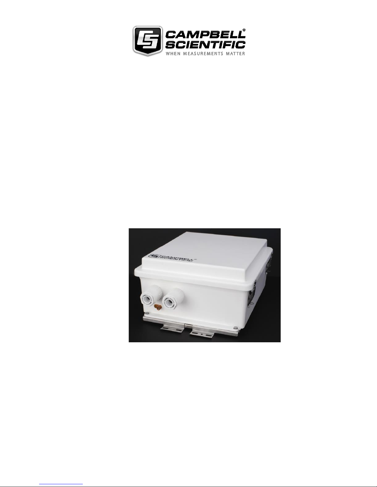
1. Description
These enclosures are made of white fibreglass-reinforced polyester. The colour of
the enclosure and the environmental sealing mean that there is no need for a
conventional radiation/rain shield. The enclosures can be wall mounted as
supplied, or pole mounted using the optional enclosure mounting brackets. The
door is fitted with a catch which can accept a padlock if required.
The enclosure is fitted with an anodised aluminium chassis plate which is punched
with an array of holes. The holes accept plastic inserts for accepting screws for the
attachment of power supplies, dataloggers and peripherals. These plastic fittings
can easily be inserted by hand allowing the rapid mounting of components inside
the enclosure.
A small cable gland is fitted to the base of the enclosure and a venting plug is
fitted to this gland. The plug allows pressure equalisation between the inside and
outside of the enclosure (which is required when using barometric or gauge
pressure transducers) and also prevents pressure build-up in the enclosure in the
event of a system failure when charging lead-acid batteries. A blanking plug is
supplied which can replace the porous venting plug, if this is not required.
We recommend that sealed environmental connectors are used for the entry of
sensor leads into the enclosure. However, a large cable gland is also fitted which
can be used for the direct entry of one or more cables into the enclosure.
An earthing boss is also provided for the connection of an external earth lead.
Internally an earth wire is fitted which should be taken to the main earth point
inside the enclosure (normally on the datalogger).
Four bags of desiccant are supplied with the enclosure and are used to maintain a
dry atmosphere inside the enclosure.
2. Installing Components in the Enclosure
When the enclosure is bought as a configured system, the components will be prefitted. If they are not fitted the convention is that the power supply (normally a
PS100E) is mounted in the top of the enclosure (this is the end opposite to that
where the cable glands are fitted). The datalogger is fitted next from the top and
then any peripherals at the bottom.
To fit the components, first work out exactly which holes are to be used and then
push the nylon inserts into the holes in the chassis plate. A 3.5mm or 6-32 thread
screw can then be screwed into the insert. Normally enough inserts and screws are
supplied with each datalogger or enclosure to cater for all peripherals.
Page 12

ENC 8/10, ENC 10/12, ENC 12/14, ENC 14/16, ENC 16/18 and AM-ENC/ENCT Enclosures
2
Some peripherals need adaptor plates for these enclosures. The
adaptor plates are not always supplied with the peripheral. Please
contact Campbell Scientific if you experience any problems.
Only one small peripheral can be fitted into the ENC 10/12 enclosure. The ENC
12/14 will take the majority of peripherals including an AM16/32, for which there
are two extra mounting holes in the lower half of the grid of holes.
Figure 2-1 ENC 12/14 fitted with a power supply, logger and multiplexer
The AM-ENC enclosure will accept up to two AM16/32s or one older (now
superseded) AM416 multiplexer.
If installing the DIN-Rail Terminal Kit (010211), follow the procedure described
in Appendix A. The 006706-002 kit facilitates wiring when many wires need to be
connected to one terminal.
3. Power Supplies
The enclosures are designed to accept the PS100E, PS17E or PS24E power
supplies. These should be mounted as described above.
Do not ship the enclosure with the large lead acid batteries
installed inside without adequate internal packing, as there is
a risk that the batteries might break loose and cause serious
damage to other peripherals.
NOTE
CAUTION
Page 13

Installation Manual
3
4. Earth Connections
Connect the earth boss on the base of the enclosure externally to a good earth
point, e.g. an array of ground spikes, using a large diameter copper cable (approx.
16mm2, similar to that supplied by Campbell Scientific with weather stations, etc.).
Internally the earth wire should be connected to the main earth point in the
enclosure, which is usually the datalogger wiring panel.
In installations where additional lighting protection devices are fitted inside the
enclosure, e.g. a RAD-SP spark arrestor, it may be more applicable to route a
separate earth wire from the boss to the arrestor, in addition to the wire to the
datalogger.
Because the chassis plate is anodised and plastic panel inserts are
used, do not rely on the chassis plate as a way of connecting the
earth points of different peripherals. Instead, run additional wires
back to one common earth point to ensure good connection.
5. Sealing the Enclosure
If supplied with environmental connectors, the enclosure is fully weatherproof
when all the connectors are plugged in and the blanking plug is fitted to the large
cable gland. If any connector is not plugged in the chassis socket should be fitted
with a protective cap to prevent moisture entry. If the large cable gland is being
used for cable entry any gaps around the cables should be filled with a suitable
mastic compound such as ‘Plumbers Mate’ or silicone rubber compound.
Do not use bath or tile sealant, which gives off corrosive
fumes that can damage circuit boards. Use proper electronic
grade silicone rubber or plumber’s putty.
6. Desiccant
The desiccant bags should be removed from the plastic bags in
which they are shipped before placing them inside the enclosure.
Four 100g bags of desiccant are supplied with each enclosure. Desiccant use
depends on your application (see below) but for use in average UK conditions
place only two bags into the enclosure and re-seal the other two bags in the plastic
shipping bag as replacements for when the initial bags need to be dried out. The
bags can be rotated in this way many times. Desiccant bags can be dried out by the
following method:
1. Arrange the bags on a wire tray in a single layer to allow for adequate air flow
around the bags during the drying process. The oven’s inside temperature
should be room or ambient temperature (25ºC - 30ºC). A CONVECTION,
CIRCULATING, FORCED AIR TYPE OVEN IS RECOMMENDED FOR
THIS REGENERATION PROCESS. SEAL FAILURES MAY OCCUR IF
ANY OTHER TYPE OF HEATING UNIT OR APPLIANCE IS USED.
2. When placed in a forced air, circulating air, or convection oven, allow a
minimum of 4 to 5 cm of air space between the top of the bags and the next
metal tray above the bags. If placed in a radiating exposed infrared element
type oven, shield the bags from direct exposure to the heating element, giving
NOTE
CAUTION
NOTE
Page 14

ENC 8/10, ENC 10/12, ENC 12/14, ENC 14/16, ENC 16/18 and AM-ENC/ENCT Enclosures
4
the closest bags a minimum of 40 cm clearance from the heat shield.
Excessive surface film temperature due to infrared radiation will cause the
Tyvek material to melt and/or the seals to fail.
Seal failure may also occur if the temperature is allowed to increase rapidly.
This is due to the fact that the water vapour is not given sufficient time to
diffuse through the Tyvek material, thus creating internal pressure within the
bag, resulting in a seal rupture. Temperature should not increase faster than
0.1º to 0.3ºC per minute.
3. Set the temperature of the oven to 118ºC, and allow the bags of desiccant to
reach equilibrium temperature. WARNING: Tyvek has a melt temperature of
121 - 127ºC. (NON MIL-D-3464E activation or reactivation of both silica gel
and Bentonite clay can be achieved at temperatures of 104ºC).
4. Desiccant bags should be allowed to remain in the oven at the assigned
temperature for 24 hours. At the end of the timer period, the bags should be
immediately removed and placed in a desiccator jar or dry (0% relative
humidity) air tight container for cooling. If this procedure is not followed
precisely, any water vapour driven off during reactivation may be re-adsorbed
during cooling and /or handling.
5. After the bags of desiccant have been allowed to cool in an airtight desiccator,
they may be removed and placed in either an appropriate type polyliner tightly
sealed to prevent moisture adsorption, or a container that prevents moisture
from coming into contact with the regenerated desiccant.
Some care should be taken when re-activating desiccant
bags. If heated in an oven which is too hot, the bags may
burst. If in any doubt, we recommend purchasing new
desiccant packs instead of oven drying.
The enclosure is supplied with a humidity indicator card, which provides a general
indication of humidity inside the enclosure and also indicates when the desiccant
bags need to be replaced. Remove the backing tape from the self-adhesive strip,
and attach the card in a suitable position on the inside wall of the enclosure.
The frequency of desiccant bag exchange varies with the application. Using the
enclosures in high humidities or where there are large daily temperature changes
will mean that the bags have to be exchanged more frequently, e.g. as frequently as
every 3-4 weeks. The desiccant in systems subject to small daily temperature
changes and moderate humidities should last for several months.
When enclosures are used on sites which have extended
maintenance periods (e.g. yearly) we strongly recommend that extra
desiccant packs are purchased and placed in the enclosure to ensure
that it remains moisture free during this period.
Fitting the blanking plug in place of the porous vent plug in the small cable gland
will greatly extend the life of the desiccant, but this is only possible in certain
applications (see above).
Failure to use or exchange the desiccant may lead to
condensation inside the enclosure. Not only will this lead to
corrupted data but, in the long term, can also cause corrosion
which is expensive to repair.
CAUTION
NOTE
CAUTION
Page 15

Installation Manual
5
7. Attachment to an Instrument Mount
7.1 Tripod Mast
The mast mount option is intended for mounting our enclosures to the mast of any
of our tripods. An enclosure ordered with this option will be shipped with a threepiece bracket for mounting on the top of the enclosure and an identical three-piece
bracket for mounting to the bottom of the enclosure (see Figures 7-1,
7-2, and 7-3).
Attach the enclosure to the mast as follows:
1. Position the enclosure on the north side of the mast.
2. Use the furnished 62 mm centre u-bolts to secure the enclosure to the tripod
mast.
3. Route the 14 AWG wire from the brass tripod grounding clamp to the
enclosure grounding lug. Strip one inch of insulation from each end of the
wire and insert the end of the wire into the grounding lugs and tighten.
Figure 7-1. An enclosure with the mast mounting option attaches
to a tripod mast via u-bolts.
Page 16

ENC 8/10, ENC 10/12, ENC 12/14, ENC 14/16, ENC 16/18 and AM-ENC/ENCT Enclosures
6
Figure 7-2. This exploded view shows the components of
a mast mounting bracket.
Figure 7-3. An enclosure attached to a tripod mast.
Page 17

Installation Manual
7
7.2 Tower mounting
The tower mount option is used to attach our enclosures to UT930, UT920, and
ATW towers. An enclosure ordered with the tower mount option will be shipped
with a three-piece bracket for fitting to the top of the enclosure and an identical
three-piece bracket for fitting to the bottom of the enclosure. This mounting
bracket option uses the same three-piece brackets as the mast mount option, except
the pieces are rearranged so that the flanges are on the side of the bracket instead
of in the middle. For the UT930 the distance between the centres of each flange
needs to be 43 cm (see Figures 7-4, 7-5, and 7-6), if mounted on the lowest section
of the tower. For other towers adjust accordingly.
Attach the enclosure to a UT930 tower as follows:
1. Remove the bolts and nuts connecting the bracket to the enclosure.
2. Slide out the flange sections so that the distance between the centres of each
flange is 43 cm (see Figure 7-4).
3. Reattach the bracket to the enclosure using the original bolts and nuts.
4. Position the enclosure on the north side of the mast.
5. Place the enclosure at the desired height. Please note that the recommended
lead lengths for our sensors assume the bottom of the enclosure is 90 cm from
the ground.
6. Use the furnished 46 mm centre u-bolts to secure the enclosure to the tower
legs.
7. Route the 14 AWG wire from the brass tower grounding clamp to the
enclosure grounding lug. Strip one inch of insulation from each end of the
wire and insert the end of the wire into the grounding lugs and tighten.
Figure 7-4. Enclosure brackets configured for a tower mount.
D
Page 18

ENC 8/10, ENC 10/12, ENC 12/14, ENC 14/16, ENC 16/18 and AM-ENC/ENCT Enclosures
8
Flange Section
Flange Section
Figure 7-5. This exploded view shows the components of
a tower mount bracket option.
Figure 7-6. An enclosure attached to two tower legs.
Page 19

Installation Manual
9
7.3 Leg Base of a CM110, CM115, CM120 Tripod
The leg mount option is intended for attaching an ENC10/12, ENC12/14, or
ENC14/16 enclosure to the leg base of a CM110, CM115, or CM120 tripod. An
enclosure ordered with this option will be shipped with a bracket attached to each
side of the enclosure and a u-bolt bracket. A #19124 bracket must also be attached
to the tripod (see Figure 4-7).
(1) For some tripods, the #19124 bracket may not be pre-installed
on the tripod at the factory. In this situation, the #19124 bracket and
mounting hardware will be shipped with the tripod and will need to
be installed as shown in Figure 7-7.
(2) An ENC16/18 cannot be mounted to the leg base.
Attach the enclosure to the leg base as follows:
1. Place the flange of the tripod’s bracket into a notch in one of the enclosure’s
bracket (see Figures 7-7, 7-8, and 7-10).
2. Attach the u-bolt bracket on the other enclosure bracket (see Figure 7-9).
3. Use the furnished 70 mm centre u-bolt to secure the enclosure bracket to a
tripod leg (see Figures 7-9 and 7-10).
4. Route the 14 AWG wire from the brass tripod grounding clamp to the
enclosure grounding lug. Strip one inch of insulation from each end of the
wire and insert the end of the wire into the grounding lugs and tighten.
Figure 7-7. The #19124 bracket attached to a CM110 tripod.
NOTES
Flange
Page 20

ENC 8/10, ENC 10/12, ENC 12/14, ENC 14/16, ENC 16/18 and AM-ENC/ENCT Enclosures
10
Notch
Figure 7-8. An ENC 14/16 enclosure with a leg mount bracket.
Figure 7-9. The u-bolt bracket.
Page 21

Installation Manual
11
Figure 7-10. An enclosure attached to the leg base of a
CM110 tripod.
8. Resistance to Weathering / Ageing
Regardless of the product range or the manufacturer, it is known that hot
compression moulded GRP is subject to erosion when used outdoors. Due to the
combined action of rain, wind and UV rays, the polyester matrix is superficially
eroded and glass fibres may become apparent. However, the depth of this erosion
is only 7µm.
This slight erosion is unavoidable unless a surface coating (e.g. varnish) is applied
(which brings with it additional problems such as adhesion). It is important to note
that any erosion is very superficial and has no effect on the physical
characteristics (electrical, mechanical or chemical) of the polyester.
Enclosures of the type supplied by Campbell Scientific have been successfully
used outdoors since 1958 and tests on field samples support laboratory results.
These enclosures are maintenance free.
If you wish to remove the appearance of any small surface scratches or scuffs
simply apply petroleum jelly (e.g. Vaseline) or oil to the surface and rub lightly.
Similarly any slight surface erosion due to weathering can be restored to its
original appearance by gently rubbing with fine sandpaper before applying
petroleum jelly.
Page 22

ENC 8/10, ENC 10/12, ENC 12/14, ENC 14/16, ENC 16/18 and AM-ENC/ENCT Enclosures
12
As of September 2009, all enclosures will be supplied with a special
surface coating to reduce surface ageing. No extra surface treating
should be necessary unless the enclosures are exposed to extreme
environments.
NOTE
Page 23

A-1
Appendix A. DIN rail terminal kits
A.1 Introduction
The 006706-002 (5-inch) or #28532 (9-inch) kit can facilitate wiring when many
wires need to be connected to one terminal. The kit contains one #15906 5-inch
DIN-Rail (or one #28531 9-inch DIN-Rail) Mounting Bracket, #505 screws,
#6044 grommets, and #15908 DIN-Rail Stoppers. A complete configuration will
also include pn #15920 Terminal Strips, pn #15907 End Plates, and pn #15909
Jumpers. The stoppers, terminal strips, and end plates are mounted onto the DINRail bracket. The DIN-Rail bracket is mounted to an enclosure backplate using
the kit’s screws and grommets.
One #15920 terminal strip consists of three spring-loaded “guillotine” terminals
that provide connection points for individual wires. Up to 20 of these terminal
strips may be fastened to the 006706-002 DIN-Rail bracket. The 006706 DINRail bracket holds up to 36. The #15907 End Plates separate the terminal strips.
The #15909 Jumpers are used to electrically connect the terminals. A stopper
needs to be on each end of the terminal strip assembly.
A.2 Installation Procedure
1. Mount the #15908 DIN-Rail Stoppers, #15920 Terminal Strips, and #15907
End Plates onto the DIN-Rail Bracket (see Figure A-1 through Figure A-3).
Figure A-1. #15908 DIN-Rail Stopper installation
Page 24

Appendix A. DIN-rail terminal kits
A-2
Figure A-2. #15920 Terminal Strip installation
Figure A-3. #15907 End Plate installation
2. Insert the #15909 Jumpers in the terminal strips as shown in Figure A-4.
Page 25

Appendix D. Default Programs
A-3
Figure A-4. #15909 Jumper installation
3. Mount the DIN-Rail bracket onto the enclosure backplate using two #505
screws and two #6044 grommets (see Figure A-5).
The 006706 includes three screws and three grommets. Use the third
screw and grommet to secure the 9-pin DIN-Rail at its centre.
Figure A-5. DIN-Rail bracket mounted onto an enclosure backplate
4. Connect the wires to the terminals (see Figure A-6 and Figure A-7). The
#8125 flat-bladed screwdriver is used to open the terminals’ guillotines for
wire entry.
NOTE
Page 26

Appendix A. DIN-rail terminal kits
A-4
Figure A-6. An installed and wired 006706-002 DIN-Rail Terminal Kit
Figure A-7. The 006706-002 DIN-Rail Terminal Kit facilitates wiring of
multiple sensors
Page 27

Page 28

CAMPBELL SCIENTIFIC COMPANIES
Campbell Scientific, Inc. (CSI)
815 West 1800 North
Logan, Utah 84321
UNITED STATES
www.campbellsci.com info@campbellsci.com
Campbell Scientific Africa Pty. Ltd. (CSAf)
PO Box 2450
Somerset West 7129
SOUTH AFRICA
www.csafrica.co.za sales@csafrica.co.za
Campbell Scientific Southeast Asia Co., Ltd.
877/22 Nirvana@Work, Rama 9 Road
Suan Luang Subdistrict, Suan Luang District
Bangkok 10250
THAILAND
www.campbellsci.asia info@campbellsci.asia
Campbell Scientific Australia Pty. Ltd. (CSA)
PO Box 8108
Garbutt Post Shop
QLD 4814 AUSTRALIA
www.campbellsci.com.au info@campbellsci.com.au
Campbell Scientific do Brazil Ltda. (CSB)
Rua Apinagés, nbr. 2018 - Perdizes
CEP: 01258-00 São Paulo SP BRAZIL
www.campbellsci.com.br
vendas@campbellsci.com.br
Campbell Scientific Canada Corp. (CSC)
14532 – 131 Avenue NW
Edmonton, Alberta T5L 4X4
CANADA
www.campbellsci.ca dataloggers@campbellsci.ca
Campbell Scientific Centro Caribe S.A. (CSCC)
300N Cementerio, Edificio Breller
Santo Domingo, Heredia 40305
COSTA RICA
www.campbellsci.cc info@campbellsci.cc
Campbell Scientific Ltd. (CSL)
80 Hathern Road, Shepshed, Loughborough LE12 9GX
UNITED KINGDOM
www.campbellsci.co.uk sales@campbellsci.co.uk
Campbell Scientific Ltd. (France)
3 Avenue de la Division Leclerc
92160 ANTONY
FRANCE
www.campbellsci.fr info@campbellsci.fr
Campbell Scientific Spain, S. L.
Avda. Pompeu Fabra 7-9
Local 1 - 08024 BARCELONA
SPAIN
www.campbellsci.es info@campbellsci.es
Campbell Scientific Ltd. (Germany)
Fahrenheitstrasse13, D-28359 Bremen
GERMANY
www.campbellsci.de info@campbellsci.de
Campbell Scientific (Beijing) Co., Ltd.
8B16, Floor 8 Tower B, Hanwei Plaza
7 Guanghua Road, Chaoyang, Beijing 100004
P.R. CHINA
www.campbellsci.com info@campbellsci.com.cn
Please visit www.campbellsci.eu to obtain contact information for your local EU or International representative .
 Loading...