

Page 1
AM16/32B
Relay Multiplexer
Revision
Copyright ©
Campbell Scientific, Inc.
: 7/18
1987 – 2018
Page 2

Limited Warranty
“Products manufactured by CSI are warranted by CSI to be free from defects in
materials and workmanship under normal use and service for twelve months
from the date of shipment unless otherwise specified in the corresponding
product manual. (Product manuals are available for review online at
www.campbellsci.com.) Products not manufactured by CSI, but that are resold
by CSI, are warranted only to the limits extended by the original manufacturer.
Batteries, fine-wire thermocouples, desiccant, and other consumables have no
warranty. CSI’s obligation under this warranty is limited to repairing or
replacing (at CSI’s option) defective Products, which shall be the sole and
exclusive remedy under this warranty. The Customer assumes all costs of
removing, reinstalling, and shipping defective Products to CSI. CSI will return
such Products by surface carrier prepaid within the continental United States of
America. To all other locations, CSI will return such Products best way CIP
(port of entry) per Incoterms ® 2010. This warranty shall not apply to any
Products which have been subjected to modification, misuse, neglect, improper
service, accidents of nature, or shipping damage. This warranty is in lieu of all
other warranties, expressed or implied. The warranty for installation services
performed by CSI such as programming to customer specifications, electrical
connections to Products manufactured by CSI, and Product specific training, is
part of CSI's product warranty. CSI EXPRESSLY DISCLAIMS AND
EXCLUDES ANY IMPLIED WARRANTIES OF MERCHANTABILITY
OR FITNESS FOR A PARTICULAR PURPOSE. CSI hereby disclaims,
to the fullest extent allowed by applicable law, any and all warranties and
conditions with respect to the Products, whether express, implied or
statutory, other than those expressly provided herein.”
Page 3

Assistance
Products may not be returned without prior authorization. The following
contact information is for US and international customers residing in countries
served by Campbell Scientific, Inc. directly. Affiliate companies handle repairs
for customers within their territories. Please visit www.campbellsci.com to
determine which Campbell Scientific company serves your country.
To obtain a Returned Materials Authorization (RMA) number, contact
CAMPBELL SCIENTIFIC, INC., phone (435) 227-9000. Please write the
issued RMA number clearly on the outside of the shipping container. Campbell
Scientific’s shipping address is:
CAMPBELL SCIENTIFIC, INC.
RMA#_____
815 West 1800 North
Logan, Utah 84321-1784
For all returns, the customer must fill out a “Statement of Product Cleanliness
and Decontamination” form and comply with the requirements specified in it.
The form is available from our website at www.campbellsci.com/repair. A
completed form must be either emailed to repair@campbellsci.com or faxed to
(435) 227-9106. Campbell Scientific is unable to process any returns until we
receive this form. If the form is not received within three days of product
receipt or is incomplete, the product will be returned to the customer at the
customer’s expense. Campbell Scientific reserves the right to refuse service on
products that were exposed to contaminants that may cause health or safety
concerns for our employees.
Page 4

Safety
DANGER — MANY HAZARDS ARE ASSOCIATED WITH INSTALLING, USING, MAINTAINING, AND WORKING ON OR AROUND
TRIPODS, TOWERS, AND ANY ATTACHMENTS TO TRIPODS AND TOWERS SUCH AS SENSORS, CROSSARMS, ENCLOSURES,
ANTENNAS, ETC. FAILURE TO PROPERLY AND COMPLETELY ASSEMBLE, INSTALL, OPERATE, USE, AND MAINTAIN TRIPODS,
TOWERS, AND ATTACHMENTS, AND FAILURE TO HEED WARNINGS, INCREASES THE RISK OF DEATH, ACCIDENT, SERIOUS
INJURY, PROPERTY DAMAGE, AND PRODUCT FAILURE. TAKE ALL REASONABLE PRECAUTIONS TO AVOID THESE HAZARDS.
CHECK WITH YOUR ORGANIZATION'S SAFETY COORDINATOR (OR POLICY) FOR PROCEDURES AND REQUIRED PROTECTIVE
EQUIPMENT PRIOR TO PERFORMING ANY WORK.
Use tripods, towers, and attachments to tripods and towers only for purposes for which they are designed. Do not exceed design limits.
Be familiar and comply with all instructions provided in product manuals. Manuals are available at www.campbellsci.com or by
telephoning (435) 227-9000 (USA). You are responsible for conformance with governing codes and regulations, including safety
regulations, and the integrity and location of structures or land to which towers, tripods, and any attachments are attached. Installation
sites should be evaluated and approved by a qualified engineer. If questions or concerns arise regarding installation, use, or
maintenance of tripods, towers, attachments, or electrical connections, consult with a licensed and qualified engineer or electrician.
General
• Prior to performing site or installation work, obtain required approvals and permits. Comply
with all governing structure-height regulations, such as those of the FAA in the USA.
• Use only qualified personnel for installation, use, and maintenance of tripods and towers, and
any attachments to tripods and towers. The use of licensed and qualified contractors is highly
recommended.
• Read all applicable instructions carefully and understand procedures thoroughly before
beginning work.
• Wear a hardhat and eye protection, and take other appropriate safety precautions while
working on or around tripods and towers.
• Do not climb tripods or towers at any time, and prohibit climbing by other persons. Take
reasonable precautions to secure tripod and tower sites from trespassers.
• Use only manufacturer recommended parts, materials, and tools.
Utility and Electrical
• You can be killed or sustain serious bodily injury if the tripod, tower, or attachments you are
installing, constructing, using, or maintaining, or a tool, stake, or anchor, come in contact with
overhead or underground utility lines.
• Maintain a distance of at least one-and-one-half times structure height, 20 feet, or the distance
required by applicable law, whichever is greater, between overhead utility lines and the
structure (tripod, tower, attachments, or tools).
• Prior to performing site or installation work, inform all utility companies and have all
underground utilities marked.
• Comply with all electrical codes. Electrical equipment and related grounding devices should be
installed by a licensed and qualified electrician.
Elevated Work and Weather
• Exercise extreme caution when performing elevated work.
• Use appropriate equipment and safety practices.
• During installation and maintenance, keep tower and tripod sites clear of un-trained or non-
essential personnel. Take precautions to prevent elevated tools and objects from dropping.
• Do not perform any work in inclement weather, including wind, rain, snow, lightning, etc.
Maintenance
• Periodically (at least yearly) check for wear and damage, including corrosion, stress cracks,
frayed cables, loose cable clamps, cable tightness, etc. and take necessary corrective actions.
• Periodically (at least yearly) check electrical ground connections.
WHILE EVERY ATTEMPT IS MADE TO EMBODY THE HIGHEST DEGREE OF SAFETY IN ALL CAMPBELL SCIENTIFIC PRODUCTS,
THE CUSTOMER ASSUMES ALL RISK FROM ANY INJURY RESULTING FROM IMPROPER INSTALLATION, USE, OR
MAINTENANCE OF TRIPODS, TOWERS, OR ATTACHMENTS TO TRIPODS AND TOWERS SUCH AS SENSORS, CROSSARMS,
ENCLOSURES, ANTENNAS, ETC.
Page 5

Table of Contents
PDF viewers: These page numbers refer to the printed version of this document. Use the
PDF reader bookmarks tab for links to specific sections.
1. Introduction ................................................................ 1
1.1 Typical Applications ............................................................................ 1
1.2 Compatibility ....................................................................................... 1
2. Precautions ................................................................ 2
3. Initial Inspection ......................................................... 2
4. QuickStart ................................................................... 2
5. Overview ..................................................................... 9
6. AM16/32B Specifications ......................................... 10
7. Installation ................................................................ 12
7.1 Wiring to Datalogger ......................................................................... 12
7.1.1 Control Terminals ....................................................................... 12
7.1.2 COM Terminals .......................................................................... 12
7.1.3 Measurement Terminals .............................................................. 13
7.2 Grounding .......................................................................................... 13
7.3 Power Supply ..................................................................................... 14
7.4 Installation in Enclosure ..................................................................... 14
8. Operation .................................................................. 14
8.1 Programming ...................................................................................... 15
8.1.1 Short Cut Programs ..................................................................... 15
8.1.2 Using CRBasic MuxSelect() Instruction ..................................... 17
8.1.3 General Programming Considerations ........................................ 17
8.1.4 Mixed Sensor Types ................................................................... 17
8.2 General Measurement Considerations ............................................... 17
8.2.1 Long Cable Lengths .................................................................... 17
8.2.2 Completion Resistors .................................................................. 17
8.2.3 Contact Degradation ................................................................... 18
Appendices
A. Importing Short Cut Code Into CRBasic Editor ... A-1
B. Example Measurements and Programs ................ B-1
B.1 Single-Ended Voltage Measurement ................................................ B-1
B.2 Differential Voltage Measurement ................................................... B-4
B.3 Half-Bridge Measurement ................................................................ B-6
i
Page 6

Table of Contents
Full-Bridge Measurement ................................................................ B-8
B.4
B.5 CR5000 Program Example ............................................................ B-12
C. Thermocouple Measurement ................................. C-1
C.1 Measurement Considerations .......................................................... C-1
C.1.1 Reference Junction ................................................................... C-1
C.1.2 Datalogger Reference ............................................................... C-1
C.1.3 AM16/32B Reference .............................................................. C-2
C.1.4 Thermal Gradients .................................................................... C-3
Figures
5-1. AM16/32B Relay Multiplexer ........................................................... 10
7-1. Example of AM16/32B-to-datalogger signal connection (4x16
mode) ............................................................................................. 13
B-1. Typical single-ended voltage measurement connection .................. B-1
B-2. Typical differential voltage measurement connection ..................... B-4
B-3. Typical half-bridge measurement connection ................................. B-6
B-4. Full-bridge measurement ................................................................. B-8
C-1. Differential thermocouple measurement with reference junction
at the datalogger ........................................................................... C-2
C-2. Differential thermocouple measurement with reference junction
at the AM16/32B (using 107-L thermistor) ................................. C-2
C-3. AM16/32B aluminum cover plate ................................................... C-3
Tables
7-1. Control Terminal Function and Datalogger Connection ................... 12
B-1. Wiring for Single-Ended Voltage Measurements CRBasic
Example ....................................................................................... B-2
B-2. Wiring for Differential Voltage Measurements CRBasic
Example ....................................................................................... B-4
B-3. Wiring for Campbell Scientific 107 Temperature Sensors
CRBasic Example ........................................................................ B-7
B-4. Wiring for Load Cells CRBasic Example ....................................... B-9
B-5. Wiring for CS616 Sensor CRBasic Example ................................ B-10
B-6. Wiring for CR5000 Program Example .......................................... B-12
CRBasic Examples
B-1. Single Ended Voltage Measurements Using MuxSelect() .............. B-2
B-2. Single-Ended Voltage Measurements ............................................. B-3
B-3. Differential Voltage Measurements Using MuxSelect() ................. B-5
B-4. Differential Voltage Measurements ................................................ B-5
B-5. Campbell Scientific 107 Temperature Sensors ............................... B-7
B-6. Load Cells ....................................................................................... B-9
B-7. CS616 Sensors............................................................................... B-11
B-8. CR5000 Program Example ............................................................ B-12
ii
Page 7

NOTE
AM16/32B Relay Multiplexer
1. Introduction
The primary function of the AM16/32B multiplexer is to increase the number
of sensors that can be measured by CR300-series, CR6-series, CR800-series,
CR1000, CR1000X-series, CR3000, and CR5000 dataloggers. The AM16/32B
is positioned between the sensors and the datalogger. Mechanical relays in the
AM16/32B connect each of the sensor channels in turn to a common output
destined for the datalogger. The user program advances the multiplexer
through the sensor channels, making measurements and storing data.
A slide switch located on the AM16/32B top panel selects one of two modes of
operation. In 2x32 mode, the multiplexer adds 32 terminal pairs. In 4x16 mode,
it adds 16 terminal groups with four terminals each. The datalogger program is
written according to the selected mode and the sensors to be measured.
The maximum number of sensors multiplexed by an AM16/32B depends
primarily on the type(s) of sensors to be measured.
This manual provides information for CRBasic dataloggers and
AM16/32Bs with serial numbers greater than 5056.
For Edlog datalogger support or for specifications for AM16/32Bs
with serial numbers less than 5056, see an older version of this
manual at www.campbellsci.com/old-manuals
1.1 Typical Applications
The AM16/32B is intended for use in applications where more terminals are
needed than the datalogger has available. Most commonly, the AM16/32B is
used to multiplex analog sensor signals, although it can also be used to
multiplex switched excitations, continuous analog outputs, or even certain
pulse counting measurements (those that require only intermittent sampling). It
is also possible to multiplex sensors of different, but compatible, types (see
Section 8.1.4, Mixed Sensor Types
1.2 Compatibility
The AM16/32B is compatible with Campbell Scientific’s CR300-series,
CR6-series, CR800-series, CR1000, CR1000X-series, CR3000, and CR5000
dataloggers.
The AM16/32B is compatible with a wide variety of commercially available
sensors. As long as relay contact current maximums are not exceeded (see
Section 2, Precautions
time, system compatibility for a specific sensor is determined by sensordatalogger compatibility.
.
(p. 17)).
(p. 2)), and no more than four lines are switched at a
1
Page 8

AM16/32B Relay Multiplexer
NOTE
2. Precautions
The AM16/32B is also compatible with the CDM-A108 and
CDM-A116 24-bit analog input modules by using the CRBasic
CDM_MuxSelect() instruction. Refer to the CRBasic Help for
information on using the AM16/32B with these modules. The
CDM-A100 Series manual includes a sample program for the
CDM-A108 and the AM16/32B.
The AM16/32B is not designed to multiplex power. Its intended function is to
switch low-level analog signals. Switched currents in excess of 30 mA will
degrade the relay contacts involved, rendering that channel unsuitable for
further low-level analog measurement. Customers who need to switch power
are directed to Campbell Scientific’s SDM-CD16AC, A6REL-12, or
A21REL-12 relays.
Changing the setting of the mode switch from 4x16 to 2x32 connects COM
ODD H to COM EVEN H and also COM ODD L to COM EVEN L. After
wiring the AM16/32B, exercise due care to avoid inadvertently putting excess
voltage on a line or short-circuiting a power supply, which might damage
connected devices such as datalogger, wiring panel, sensor, or multiplexer, and
which would not be covered under warranty.
3. Initial Inspection
• The AM16/32B ships with:
o 4 grommets
o 4 screws
• Upon receipt of the AM16/32B, inspect the packaging and contents for
damage. File damage claims with the shipping company.
• Immediately check package contents. Thoroughly check all packaging
material for product that may be concealed. Check model number, part
numbers, and product descriptions against the shipping documents. Model
or part numbers are found on each product. On cables, the number is often
found at the end of the cable that connects to the measurement device.
Ensure that the expected lengths of cables were received. Contact
Campbell Scientific immediately if there are any discrepancies.
4. QuickStart
Short Cut is an easy way to program your datalogger to make measurements
through an AM16/32B multiplexer. Short Cut is included in installations of
LoggerNet, PC400, PC200W, and RTDAQ. It is also available as a download
on www.campbellsci.com.
2
This section will guide you through programming a datalogger to measure 6
Campbell Scientific 107 temperature sensors as an example for creating a
program using a multiplexer. With minor changes, these steps can apply to
other measurements and dataloggers.
Page 9
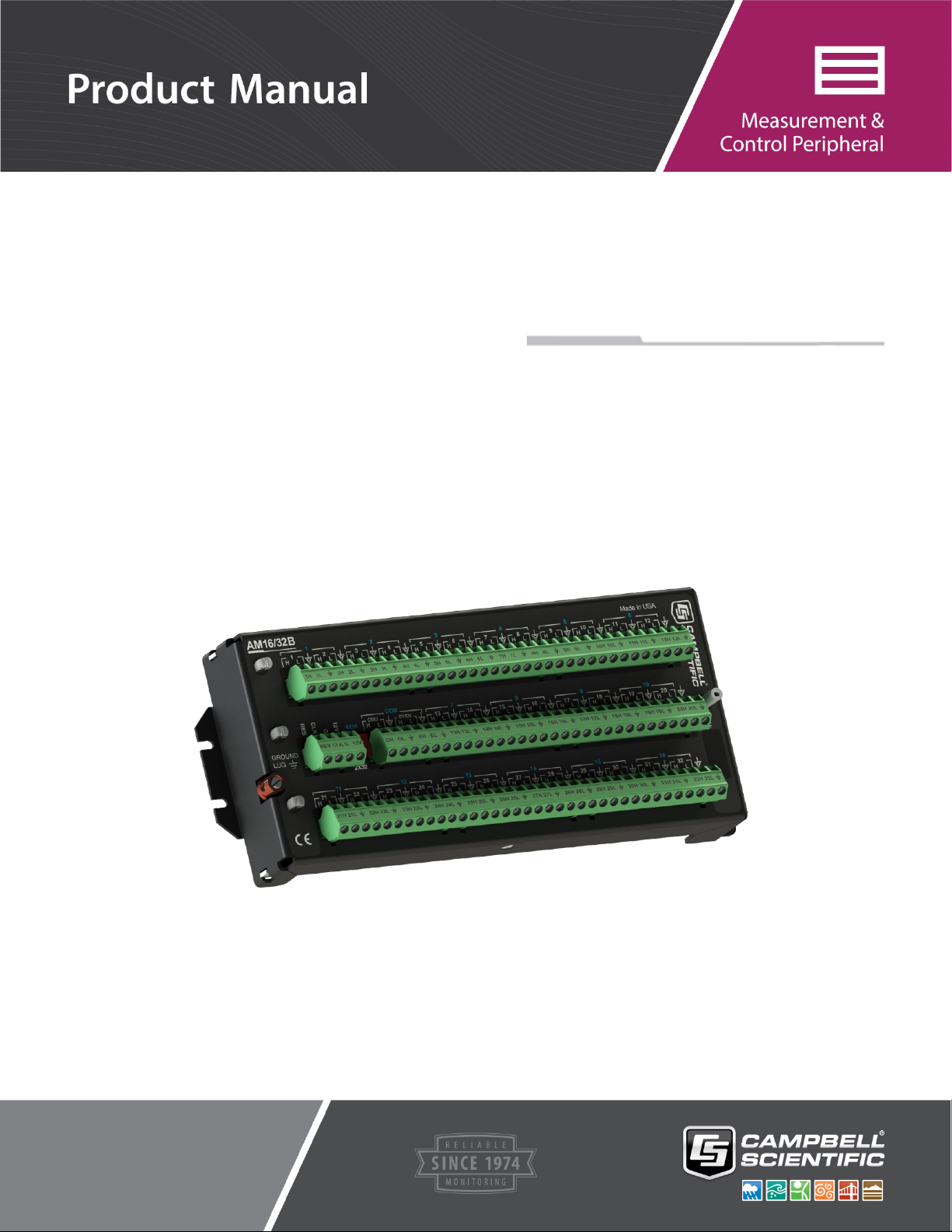
Open Short Cut. From the
LoggerNet toolbar, click Program |
Short Cut. In PC200W and PC400,
click on the Short Cut icon.
Select Create New Program.
AM16/32B Relay Multiplexer
NOTE: The first time Short Cut is
run, a prompt will appear asking for
a choice of first notch frequency.
Select 60 Hz Noise Rejection for
the United States and areas using
60 Hz ac voltage. Select 50 Hz
Noise Rejection for most of Europe
and areas that operate at 50 Hz.
3
Page 10
AM16/32B Relay Multiplexer
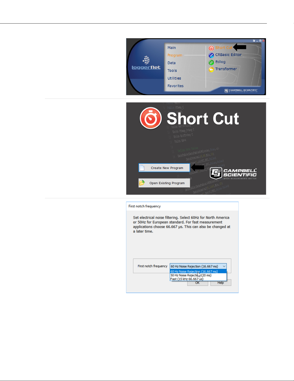
A second prompt lists sensor
support options. Campbell
Scientific, Inc. (US) is probably the
best fit if you are outside Europe.
To change the first notch frequency
or sensor support option for future
programs, use the Program menu.
Select your datalogger model in the
Datalogger Model drop-down list.
This tutorial uses the CR6-series
datalogger.
4
Page 11

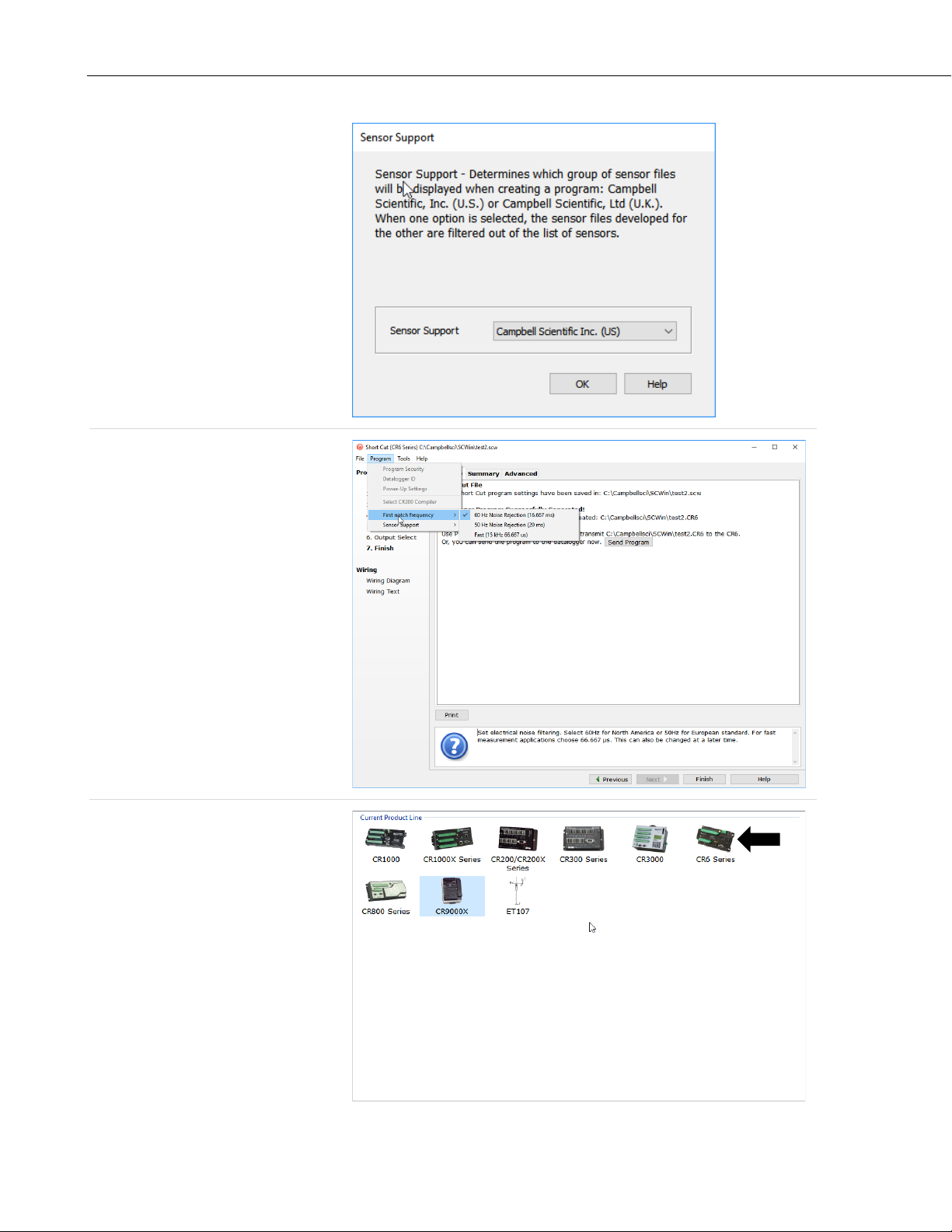
The Progress Bar is used to track
the progress of the program being
created. It is also used to jump
directly to any step in the
programming process.
The next window displays
Available Sensors and Devices.
Expand a folder by clicking on the
symbol. Expand the Devices
folder, then double-click on the
AM16/32 to add it to the Selected
panel.
AM16/32B Relay Multiplexer
5
Page 12
AM16/32B Relay Multiplexer
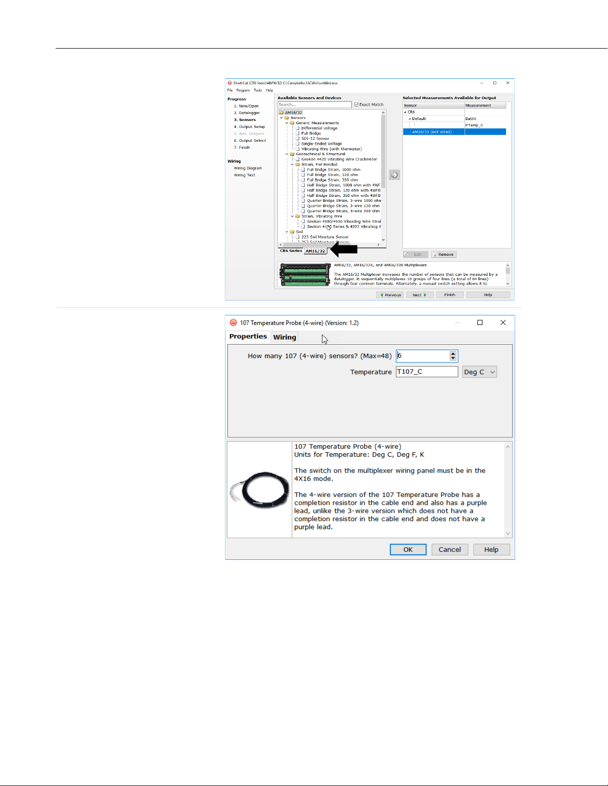
When the AM16/32 multiplexer is
added as a device, a new AM16/32
tab will appear at the bottom of the
Available Sensors and Devices
pane. With the AM16/32 tab
selected, select the Sensors |
Temperature subfolder.
Double-click on 107 Temperature
Probe (4-wire).
In the resulting window, enter the
number of 107 temperature probes
to measure on this AM16/32B
multiplexer. For this tutorial, enter 6
as the number of 107 (4-wire)
sensors to add. Click OK in the
dialog window to accept the default
name of T107_C and the default
units of Deg C.
6
Page 13
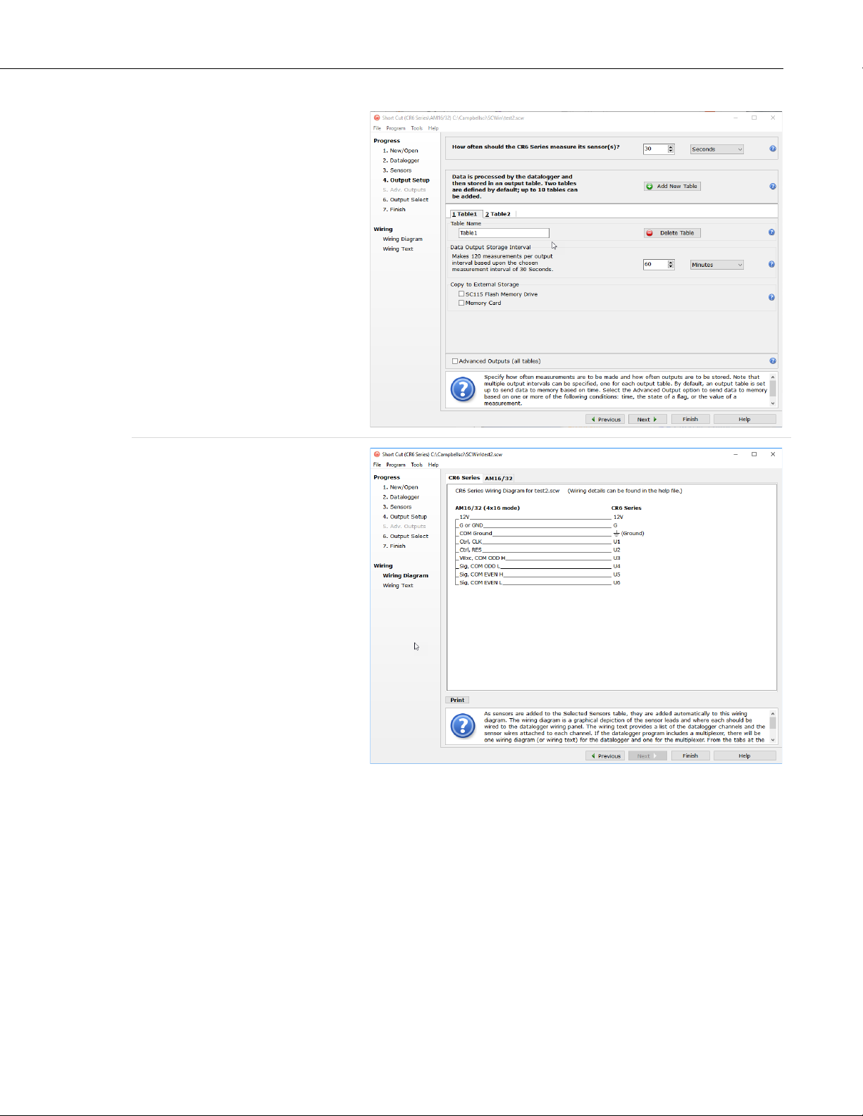
In the Scan Interval box, enter how
frequently the datalogger should
make measurements. When
measuring with an AM16/32B
multiplexer, we recommend an
interval of 30 seconds or longer.
Enter 30 and select Seconds.
Click Next.
AM16/32B Relay Multiplexer
After adding the measurements,
click Wiring Diagram to see how
the sensors are to be wired to the
AM16/32B and how the AM16/32B
is to be wired to the datalogger. The
datalogger tab (CR6 Series in this
example) shows the connection
between the AM16/32B and the
datalogger, and the AM16/32 tab
shows the sensor connection to the
AM16/32B.
7
Page 14

AM16/32B Relay Multiplexer
With power disconnected, wire the
sensors and devices as shown in the
wiring diagrams. Insert the wires,
taking care to tighten the terminals
on the conductors themselves, not
the insulation.
Click on Sensors in the Progress
list to return to the sensor-selection
screen.
Select any other sensors you have in
the Sensors section. Add sensors to
the datalogger by selecting the
datalogger tab (CR6 in this
example). Add sensors to the
multiplexer by selecting the
AM16/32 tab.
Finish the remaining Short Cut steps
to complete the program. The
remaining steps are outlined in Short
Cut Help, which is accessed by
clicking on Help | Short Cut Help |
Contents | Programming Steps.
8
Page 15

AM16/32B Relay Multiplexer
After powering on and sending the program to the datalogger, check the output of sensors in the datalogger
support software data display to make sure they are making reasonable measurements.
If LoggerNet, PC200W, PC400, or
RTDAQ is running on your
computer and the computerto-datalogger connection is active,
you can click Finish in Short Cut,
and you will be prompted to send
the program just created to the
datalogger.
5. Overview
Under datalogger control, the AM16/32B sequentially connects terminal pairs
or groups to datalogger terminals. This effectively expands the number of
terminals available on a datalogger.
FIGURE 5-1 shows the wiring panel of the AM16/32B multiplexer. The group
of four terminals located near the mode switch are dedicated to the connection
of datalogger power and control lines. COM ODD and EVEN terminals on the
other side of the mode switch carry multiplexed signals destined for datalogger
terminals. The remaining terminals on the AM16/32B are for sensor and
sensor-shield connection. All of the inputs of the AM16/32B are protected
against surges with transient suppression. Datalogger-to-AM16/32B cabling
requires a minimum of six and as many as nine individually insulated wires
with shields.
9
Page 16

AM16/32B Relay Multiplexer
FIGURE 5-1. AM16/32B Relay Multiplexer
6. AM16/32B Specifications
1, 2
Power
: Unregulated 9.6 to 16 Vdc
Current Drain
Quiescent: < 210 µA
Active: 6 mA typical in 2x32 mode
11 mA typical in 4x16 mode
1
: A continuous signal between 3.3 Vdc and
Reset
8 Vdc holds the AM16/32B in an active state
(where a clock pulse can trigger a channel
advance). A signal voltage < 0.9 Vdc
deactivates the AM16/32B (clock pulse will
not trigger a channel advance; AM16/32B is
also reset).
1
: On the transition from <1.5 V to >3.3 V, a
Clock
channel advance is actuated on the leading
edge of the clock signal; clock pulse should be
a minimum of 1 ms wide; maximum voltage is
8 Vdc.
Operational Temperature
Standard: –25 to 50 °C
Extended: –55 to 85 °C
Operational Humidity: 0 to 95%, non-condensing
Dimensions
Length: 23.9 cm (9.4 in)
Width: 10.2 cm (4.0 in)
Depth: 4.6 cm (1.8 in)
10
Weight: 680 g (1.5 lb) (approx.)
Page 17

AM16/32B Relay Multiplexer
Mounting Tab
Hole Spacing: 1 x 3 x 9 in. Up to 1/8 in or 3 mm diameter
screws.
3
Expandability
(nominal): 1 AM16/32B per CR300
4 AM16/32Bs per CR6
2 AM16/32Bs per CR800/CR850
4 AM16/32Bs per CR1000
4 AM16/32Bs per CR1000X
4 AM16/32Bs per CR3000
4 AM16/32Bs per CR5000
Maximum Cable Length: Depends on sensor and scan rate. In general,
longer lead lengths necessitate longer
measurement delays. Refer to datalogger and
sensor manuals for details.
Maximum
4
Switching Current
: 500 mA
Contact Specifications
Initial Contact Resistance: <0.1 Ω max.
Initial Contact Bounce: <1 ms
Contact Material: Silver Palladium
Wiper to N.O. Contact
Capacitance: 0.5 pF
Typical Low-current
7
(<30 mA) Life: 5 x 10
operations
Maximum Contact
Voltage Rating: 70 V
Relay Switching
Thermal emf: 0.3 µV typical; 0.5 µV maximum
Operate Time: <10 ms over temperature and supply ranges
Break-before-make guaranteed by design.
Relays disengage from previous selected
channel before engaging next channel.
ESD
Air Discharge: complies with IEC61000-4-2, test level 4
(±15 kV)
Contact Discharge: complies with IEC61000-4-2, test level 4
(±8 kV)
Surge: Complies with IEC61000-4-5, test level 3
(±2 kV, 2 ohms coupling impedance)
Compliance: View EU Declaration of Conformity at
www.campbellsci.com/am16-32b
1
Reset and clock protected by 8 V varistors; +12 V input is protected by +16 V
TransZorb®.
2
For power specifications on serial numbers less than 5056, refer to an older version of
this manual at www.campbellsci.com/old-manuals.
11
Page 18

AM16/32B Relay Multiplexer
TABLE 7-1. Control Terminal Function and Datalogger Connection1
Terminal
Function
Datalogger Connection Terminal
12V
12V
RES
C, U
⏚
7. Installation
7.1 Wiring to Datalogger
7.1.1 Control Terminals
3
Assumes sequential activation of multiplexers and that each datalogger channel is
uniquely dedicated. If the application requires additional multiplexing capability, please
consult Campbell Scientific for application assistance.
4
Switching currents greater than 30 mA (occasional 50 mA current is acceptable) will
degrade the contact surfaces of the mechanical relays and increase their resistance. This
will adversely affect the suitability of these relays to multiplex low voltage signals.
Although a relay used in this manner no longer qualifies for low voltage measurement,
it continues to be useful for switching currents in excess of 30 mA.
If you are programming your datalogger with Short Cut, skip Section 7.1,
Wiring to Datalogger. Short Cut creates a wiring diagram for you. See Section
4, QuickStart
(p. 2), for a Short Cut tutorial.
Removable terminal strips allow wiring to remain intact while the multiplexer
is used elsewhere. The green terminal strips are easily removed; no tools are
required. Replacement terminal strips may be purchased from Campbell
Scientific.
TABLE 7-1 depicts control connections to Campbell Scientific dataloggers.
1
Connect the cable shield to G on the AM16/32B and to G on the CR6 series, CR800
series, CR1000, or CR3000. Connect to
7.1.2 COM Terminals
The four terminals dedicated to multiplexer-datalogger connection are located
under the blue COM label next to the mode switch. The terminals are labeled:
ODD H/L and EVEN H/L. In 4x16 mode, the AM16/32B maintains the four
COM terminals electrically isolated from one another. In 2x32 mode, the
AM16/32B maintains an internal connection between ODD H and EVEN H
and between ODD L and EVEN L. How the COM terminals connect to
datalogger terminals determines the function of the measurement terminals. For
proper function, these terminals must be wired according to the measurement
instructions in the CRBasic program. See Section 8, Operation
and Appendix B, Example Measurements and Programs
Control
Power
G
Power
ground
CLK Clock
Reset
G (power ground)
C (control port), U (universal) terminal
configured for control
terminal configured for control
on the CR5000.
(p. 14), for details
(p. B-1), for examples.
12
Page 19

AM16/32B Relay Multiplexer
Common
terminals. They connect internally to the other thirty-two
terminals are provided next to the COM ODD and COM EVEN
terminals on the
AM16/32B and are connected at all times (not switched). Their function is to
provide a path to ground for sensor cable shields. A COM
terminal should be
wired to datalogger ground (⏚) as shown in FIGURE 7-1.
FIGURE 7-1. Example of AM16/32B-to-datalogger signal connection
(4x16 mode)
7.1.3 Measurement Terminals
Wire sensors and transducers according to the COM terminal connections and
the measurement instructions in the CRBasic program. See Section 8,
Operation
Programs
(p. 14) for details and Appendix B, Example Measurements and
(p. B-1), for examples.
7.2 Grounding
The AM16/32B has a ground lug that should be connected to earth ground via
an 8 AWG wire. This connection should be as short as possible. The ground
lug provides a path to dissipate surges that might propagate on a sensor shield
line. An 8 V, bi-polar TransZorb® connects shield ground to the ground lug.
The AM16/32B GND terminal is connected to datalogger power ground. The
AM16/32B GND terminal is also connected to the cable shield and, via that, to
datalogger power ground (see TABLE 7-1). If a separate power supply is used,
the AM16/32B ground should also connect to the power supply ground. An
AM16/32B COM
via the cable that connects the COM terminals (see FIGURE 7-1). The
datalogger must connect to earth ground by one of the methods described in the
installation and maintenance section of the datalogger manual.
terminal should connect to a datalogger signal ground (⏚)
13
Page 20

AM16/32B Relay Multiplexer
NOTE
7.3 Power Supply
7.4 Installation in Enclosure
The AM16/32B requires a continuous power supply for operation. The positive
side of the power supply is connected to 12V, and the negative side is
connected to G. Connect the G wire first for safety.
The average power required to operate an AM16/32B depends on the
percentage of time it is active per time period. At a minimum, the power supply
must be able to sustain the system between site visits anticipating the worst
environmental extremes. Refer to the application note Power Supplies and the
video Power Budgeting , both available at www.campbellsci.com, for more
help in selecting a power supply.
The AM16/32B must be protected from moisture. Moisture in the electronics
will seriously damage the AM16/32B. In most cases, protection from water is
easily accomplished by placing the AM16/32B in a weathertight enclosure with
desiccant and elevating the enclosure above the ground. Desiccant in
enclosures should be changed periodically.
Mount the AM16/32B to an enclosure backplate by inserting the included
screws through the mounting holes in the AM16/32B and into the included
grommets.
8. Operation
The reset (RES) line is used to switch on the AM16/32B by applying 3.3 to 8
Vdc. When this line drops lower than 0.9 Vdc, the multiplexer enters a
quiescent, low current-drain state. In the quiescent state, the common (COM)
terminals are electrically disconnected from all of the sensor input channels.
RES should always connect to a datalogger terminal configured for control.
The PortSet() instruction controls the reset line.
After RES has been set high, a pulse on CLK advances the channels. The
voltage level must fall below 1.5 Vdc and then rise above 3.3 Vdc to clock the
multiplexer. In a typical operation, this is accomplished with either the
PulsePort() or PortSet() instruction. Another method of operation uses the
MuxSelect() instruction to advance to a channel specified in the instruction.
When RES first goes high, the COM terminals (ODD H, ODD L and EVEN
H, EVEN L) are disconnected from all measurement terminals. When the first
CLK pulse arrives, the COM terminals are switched to connect with the first
set of measurement terminals according to the mode switch, either 4x16 or
2x32. When a second CLK pulse arrives, the common lines are switched to
connect to the second set of measurement terminals. The multiplexer advances
a channel on the rising edge of the CLK pulse.
The CLK pulse should be at least 1 ms long. A delay (typically 10
ms or more) is inserted between the beginning of the CLK pulse
and the measurement instruction to ensure sufficient settling time
to relay contacts.
14
Page 21

AM16/32B Relay Multiplexer
NOTE
NOTE
The terminals for sensor attachment are divided into 16 groups (panel switch
set to 4x16) or into 32 groups (panel switch set to 2x32). The groups consist of
four or two Simultaneously Enabled Terminals (SETs). With the panel switch
set to 4X16, the blue channel numbers apply. The SETs are numbered starting
at 1 (1H, 1L, 2H, 2L) and continuing until SET 16 (31H, 31L, 32H, 32L).
In 4x16 mode, the odd-numbered terminals (example: 5H, 5L) are relayswitched to the COM ODD terminals while the even terminals (6H, 6L) are
switched to the COM EVEN terminals. When activated by the RES line, as
the AM16/32B receives clock pulses from the datalogger, each SET of four in
turn is switched into contact with the four COM terminals. For example, when
the first clock pulse is received from the datalogger, SET 1, consisting of 1H,
1L, 2H, and 2L, is connected to COM ODD H, ODD L, EVEN H, and
EVEN L terminals respectively. When the second clock pulse is received, the
first SET is switched out (SET 1 sensor inputs become open circuits), and SET
2 (3H, 3L, 4H, 4L) are connected to the four COM terminals. A given SET
will typically be connected to the common terminals for 10 ms.
With the panel switch set to 2X32, the white channel numbers apply. The SETs
are labeled beginning with 1H, 1L and ending with 32H, 32L. In 2x32 mode
when the AM16/32B selects a given channel, the H terminal is relay-connected
to both COM H terminals, and the L sensor terminal is connected to both
COM L terminals.
8.1 Programming
8.1.1 Short Cut Programs
In most cases, Short Cut is the best way to create or begin datalogger programs
for the AM16/32B multiplexer. See Section 4, QuickStart
tutorial. The details that follow pertain to CRBasic programs generated by
Short Cut. For measurement and program examples, see Appendix B, Example
Measurements and Programs
To accommodate the AM16/32 and AM16/32A, Short Cut adds a
delay of 150 ms after disabling the multiplexer. This delay is not
required for the AM16/32B and may be deleted to increase the
speed of the program.
When programming with Short Cut, three instructions operate the multiplexer:
1) the PortSet() instruction enables or disables the multiplexer, 2) the
SubScan()/NextSubScan instruction begins/ends the measurement loop, and
3) the PulsePort() instruction clocks through the measurement channels. The
CRBasic program must also specifically increment an index variable and use
that variable to determine where each measurement is stored. The generalized
programming sequence follows:
The CR5000 does not support the PulsePort() instruction. Refer
to CRBasic Example B-8, CR5000 Program Example (p. B-12), for
this datalogger.
(p. 2), for a Short Cut
(p. B-1).
15
Page 22

AM16/32B Relay Multiplexer
'Turn AM16/32B Multiplexer on
PortSet(2,0)
PortSet(2,1)
Delay(0,150,mSec)
'Reset counter
LCount=1
'Begin measurement loop
SubScan(0,uSec,5) 'measures 5 sets
'Switch to next AM16/32B Multiplexer channel
PulsePort(1,10000)
'Make measurements
'Increment counter according to measurement mode
LCount=LCount+1
NextSubScan
'Turn AM16/32 Multiplexer off
The SubScan() instruction is used to create a measurement loop for the
multiplexer. The third parameter in the SubScan() instruction, Count, is the
number of sets on the multiplexer that will be used. For example, if the
instruction is SubScan(0,μSec,7) and the multiplexer is in 2x32 mode, the first
seven terminal pairs (numbers in white) on the multiplexer will be used. When
in 4x16 mode, this instruction will use the first seven groups of four (numbers
in blue) on the multiplexer.
It may be desirable to use the repetition parameter, Reps, of the measurement
instructions between SubScan() and NextSubScan. The repetitions parameter
is the number of sensors per instruction that will be measured. See the
examples below:
Example 1
'Example 1
LCount = 1
SubScan (0,uSec,7)
PulsePort (C1,10000)
VoltDiff (Dest(LCount),1,mV5000,1,True ,0,60,1.0,0)
LCount = LCount + 1
NextSubScan
In this example, one measurement is made per VoltDiff() instruction because
the instruction has a repetition parameter of 1 (the second parameter in the
VoltDiff() instruction). With the multiplexer in 2x32 mode, differential voltage
measurements will be made on the first seven 2x32 terminal pairs because the
Count parameter of the SubScan() instruction is 7.
Example 2
'Example 2
LCount = 1
SubScan (0,uSec,7)
PulsePort (C1,10000)
VoltDiff (Dest(LCount),2,mV5000,1,True ,0,60,1.0,0)
LCount = LCount + 2
NextSubScan
With the multiplexer in 4x16 mode, differential voltage measurements will be
made on the first seven 4x16 terminal groups because the Count parameter of
the SubScan() instruction is 7. Two differential sensors are measured per
terminal group because the VoltDiff() instruction has a repetition parameter of
2. Thus, a total of 14 differential voltage measurements will be made (2
measurement per subscan • 7 subscans = 14).
16
Page 23

8.1.2 Using CRBasic MuxSelect() Instruction
'Turn AM16/32B Multiplexer on, C1-CLK, C2-RES
PortSet(C2,0)
The CRBasic MuxSelect() instruction is used to enable the multiplexer and
select a specific channel to begin measurements. This can simplify your
datalogger program by making one set of measurements at a time. Use the
PulsePort() instruction to advance the multiplexer and the PortSet()
instruction to disable it. The generalized programming sequence follows:
'Advance to first measurement channel in SET 1
MuxSelect (C1, C2 ,20,1,1)
'Make SET 1 measurements
'<insert measurement instruction(s)>
'Advance to first measurement channel in SET 2
PulsePort (C1 ,10000) 'move to Set 2
'Make SET 2 measurements
'<insert measurement instruction(s)>
'Advance to first measurement channel in SET 3
PulsePort (C1 ,10000) 'move to Set 3
'Make SET 3 measurements
'<insert measurement instruction(s)>
'Turn AM16/32 Multiplexer off
For measurement and program examples, see Appendix B, Example
Measurements and Programs
(p. B-1).
AM16/32B Relay Multiplexer
8.1.3 General Programming Considerations
8.1.4 Mixed Sensor Types
8.2 General Measurement Considerations
8.2.1 Long Cable Lengths
Excitation voltage, integration time, and delay time associated with measuring
the signal, and the speed at which the channels are advanced, can be varied
within the datalogger program. In general, longer delay times are necessary
when sensors and datalogger are separated by longer lead lengths. Consult the
datalogger or sensor manual for additional information on these topics.
In applications where sensor types are mixed, experienced programmers can
create multiple configurations, though it is preferred to use multiple
multiplexers for these situations. When programming for mixed sensors on a
single AM16/32B, it is especially important to verify that each measurement is
reasonable. Consult Campbell Scientific for application assistance when it is
necessary to multiplex markedly different sensor types in an application.
Longer sensor-to-AM16/32B cables result in greater induced and capacitively
coupled voltages (cross talk) between cable wires. It may also be necessary to
program a delay within the measurement instruction to allow time for lead-wire
capacitances to discharge after advancing a channel, before the measurement is
made. This can be done by increasing the Delay parameter in the PulsePort()
instruction or by adding a Delay() instruction after the PulsePort() instruction.
A delay of 20 ms or more is recommended.
8.2.2 Completion Resistors
In some applications, it is advantageous to place completion resistors at the
AM16/32B terminal strips. Certain sensors specific to the use of multiplexers
17
Page 24

AM16/32B Relay Multiplexer
8.2.3 Contact Degradation
are available from Campbell Scientific. Examples include soil moisture probes
and thermistor probes.
Once excitation in excess of 30 mA has been multiplexed, that channel’s relay
contacts have been rendered unsuitable for further low voltage measurement.
To prevent undue degradation, it is advisable to reserve certain channels for
sensor excitation and employ other channels for sensor signals.
Refer to Section 2, Precautions
degradation.
(p. 2), for more information on contact
18
Page 25

NOTE
Appendix A. Importing Short Cut Code Into CRBasic Editor
This tutorial shows:
• How to import a Short Cut program into a program editor for
additional refinement
• How to import a wiring diagram from Short Cut into the comments of
a custom program
Short Cut creates files, which can be imported into CRBasic Editor. Assuming
defaults were used when Short Cut was installed, these files reside in the
C:\campbellsci\SCWin folder:
• .DEF (wiring and memory usage information)
• .CR6 (CR6-series datalogger code)
• .CR8 (CR800-series datalogger code)
• .CR1 (CR1000 datalogger code)
• .CR1X (CR1000X-series datalogger code)
• .CR3 (CR3000 datalogger code)
• .CR5 (CR5000 datalogger code)
Use the following procedure to import Short Cut code and wiring diagram into
CRBasic Editor.
1. Create the Short Cut program following the procedure in Section 4,
QuickStart
CRBasic Editor button. The program opens in CRBasic with the name
noname.CR_. Now save the program with your desired name in any
folder.
Once the file is edited with CRBasic Editor, Short Cut can no
longer be used to edit the datalogger program. Change the name
of the program file or move it, or Short Cut may overwrite it next
time it is used.
2. The program can now be edited, saved, and sent to the datalogger.
3. Import wiring information to the program by opening the associated .DEF
file. By default, it will be in the c:\campbellsci\SCWin folder. Copy and
paste the section beginning with heading “–Wiring for CRXXX–” into the
CRBasic program, usually at the head of the file. After pasting, edit the
information such that an apostrophe (') begins each line. This character
instructs the datalogger compiler to ignore the line when compiling. You
can highlight several lines of CRBasic code then right-click and select
Comment Block. (This feature is demonstrated at about 5:10 in the
CRBasic | Features video.)
(p. 2). Finish the program. On the Advanced tab, click the
A-1
Page 26

Appendix B. Example Measurements and Programs
This section covers sensor-to-AM16/32B connections and AM16/32B-todatalogger connections. Most programs were created in Short Cut. The
following are examples only and should not be construed as the only way to
make a particular measurement. See the measurement section of the datalogger
manual for more information on basic bridge measurements. Most of the
following examples do not depict datalogger-to-AM16/32B control
connections (Section 7.1.1, Control Terminals
implied and required.
B.1 Single-Ended Voltage Measurement
FIGURE B-1 shows a typical connection for single-ended voltage
measurements. Using this method, a datalogger can make up to 48 singleended voltage measurements through a multiplexer. See CRBasic Example
B-1, CRBasic Example B-2, and TABLE B-1 for a related program and wiring
diagram, or use Short Cut to create your own.
(p. 12)), but their presence is
FIGURE B-1. Typical single-ended voltage measurement connection
B-1
Page 27

Appendix B. Example Programs
TABLE B-1. Wiring for Single-Ended Voltage Measurements CRBasic Example
⏚ (
⏚ (
⏚
⏚
CRBasic Example B-1. Single Ended Voltage Measurements Using MuxSelect()
'Multiplexer in 4X16 Mode
PulsePort (C1 ,10000) 'to move to Set 3
CR1000X CR300
AM16/32B in 4X16 Mode
Control and
COM Terminals
Measurement
Terminals
Sensors
Signal
Ground
)
1H 1H COM ODD L Odd-numbered L terminal Sensor 1 signal
1L 1L COM EVEN H Even-numbered H terminal Sensor 2 signal
2H 2H COM EVEN L Even-numbered L terminal Sensor 3 signal
12V SW12V 12V
G G G
C1 C1 CLK
C2 C2 RES
'Declare Variables and Units
Public SEVolt(9)
Units SEVolt=mV
'Define Data Tables
DataTable (Hourly,True,-1)
DataInterval(0,60,Min,10)
Sample(9,SEVolt(),FP2)
EndTable
DataTable(Daily,True,-1)
DataInterval(0,1440,Min,10)
Average (9,SEVolt(),FP2,False)
EndTable
'Main Program'
BeginProg
SW12 (1 ) 'provide power to AM16/32B
'Main Scan
Scan(30,Sec,1,0)
'>>>>>> Set 1
'Turn AM16/32B Multiplexer On, start measurements on mux channel 1
MuxSelect (C1,C2 ,20,1,1)
'3 repetitions, writing to SEVolt(1), SEVolt(2) and SEVolt(3)
'3 repetitions, measuring 1H, 1L, 2H on mux
VoltSe(SEVolt(1),3,mv2500,1,True,0,60,1,0)
'>>>>>> Set 2
PulsePort (C1 ,10000) 'to move to Set 2
'start measurements on mux channel 3
'3 repetitions, writing to SEVolt(4), SEVolt(5) and SEVolt(6)
'3 repetitions, measuring 3H, 3L, 4H on mux
VoltSe(SEVolt(4),3,mv2500,1,True,0,60,1,0)
'>>>>>> Set 3
Signal
Ground
)
COM ODD H Odd-numbered H terminal Sensor 1, 2, and 3 grounds
COM
Sensor 1, 2, and 3 shields
CRBasic Example B-1 is a CR300-series program. With minor adjustments,
this program can be used with the CR1000X series, CR6 series, CR800 series,
CR1000, or CR3000. The AM16/32B must be in 4x16 mode.
B-2
Page 28

'3 repetitions, writing to SEVolt(7), SEVolt(8) and SEVolt(9)
'3 repetitions, measuring 5H, 5L, 6H on mux
EndProg
CRBasic Example B-2. Single-Ended Voltage Measurements
'Declare Variables and Units
EndProg
VoltSe(SEVolt(7),3,mv2500,1,True,0,60,1,0)
'Turn AM16/32B Multiplexer Off
PortSet(C2,0)
'Call Data Tables and Store Data
CallTable Hourly
CallTable Daily
NextScan
The following example is a CR1000X program. With minor adjustments, this
program can be used with the CR6 series, CR800 series, CR1000, or CR3000.
The AM16/32B must be in 4x16 mode.
Public BattV
Public Ptemp_C
Public LCount
Public SEVolt(48)
Units BattV=Volts
Units Ptemp_C=Deg C
Units SEVolt=mV
'Define Data Tables
DataTable (Hourly,True,-1)
DataInterval(0,60,Min,10)
Sample(48,SEVolt(),FP2)
EndTable
DataTable(Daily,True,-1)
DataInterval(0,1440,Min,10)
Average (48,SEVolt(),FP2,False)
Minimum(1,BattV,FP2,False,False)
EndTable
'Main Program'
BeginProg
'Main Scan
Scan(30,Sec,1,0)
'Default CR1000X Datalogger Battery Voltage measurement 'BattV'
Battery(BattV)
'Default CR1000X Datalogger Wiring Panel Temperature measurement 'PTemp_C'
PanelTemp(Ptemp_C,_60Hz)
'Turn AM16/32B Multiplexer On
PortSet(C2,1)
Delay(0,150,mSec)
LCount=1
SubScan(0,uSec,16)
'Switch to next AM16/32B Multiplexer channel
PulsePort(C1,10000)
'Generic Single Ended Voltage measurements 'SEVolt() on AM16/32B Multiplexer
VoltSe(SEVolt(LCount),3,mv5000,1,True,0,_60Hz,1,0)
LCount=LCount+3
NextSubScan
'Turn AM16/32B Multiplexer Off
PortSet(C2,0)
'Call Data Tables and Store Data
CallTable Hourly
CallTable Daily
NextScan
Appendix B. Example Programs
B-3
Page 29

Appendix B. Example Programs
TABLE B-2. Wiring for Differential Voltage Measurements CRBasic Example
⏚ (
⏚ (
B.2 Differential Voltage Measurement
FIGURE B-2 shows a typical connection for differential voltage
measurements. Using this method, a datalogger can make up to 32 differential
voltage measurements through a multiplexer. See CRBasic Example B-3,
CRBasic Example B-4, and TABLE B-2 for related programs and wiring
diagram, or use Short Cut to create your own.
FIGURE B-2. Typical differential voltage measurement connection
Notice that these programs use arrays for multipliers and offsets. This allows
you to adjust multipliers and offsets for each sensor individually. For example,
in this program the third multiplier, 8, and the third offset, 9, would be applied
to the third measurement, DiffV(3).
CR300 AM16/32B in 2X32 Mode
CR1000X
1H 1H COM ODD H H High signal
1L 1L COM ODD L L Low signal
Signal Ground)
12V SW12V 12V
G G G
C1 C1 CLK
C2 C2 RES
Signal Ground)
CRBasic Example B-3 is a CR300-series program. With minor adjustments,
this program can be used with the CR1000X series, CR6 series, CR800 series,
CR1000, or CR3000. The AM16/32B must be in 2x32 mode.
Control and
COM Terminals
COM
Measurement Terminals
Sensors
Shield
B-4
Page 30

CRBasic Example B-3. Differential Voltage Measurements Using MuxSelect()
'Multiplexer in 2X32 mode
CRBasic Example B-4. Differential Voltage Measurements
'Declare Variables and Units
'Define Data Tables
Appendix B. Example Programs
'Declare Variables and Units
Public DiffV(3)
Public Mult(3)={9,1,8}
Public Offs(3)={5,4,9}
Units DiffV=mV
'Define Data Tables
DataTable (Hourly,True,-1)
DataInterval(0,60,Min,10)
Sample(3,DiffV(),FP2)
EndTable
DataTable(Daily,True,-1)
DataInterval(0,1440,Min,10)
Average (3,DiffV(),FP2,False)
EndTable
'Main Program'
BeginProg
SW12 (1 ) 'provide power to AM16/32B
'Main Scan
Scan(30,Sec,1,0)
'>>>>>> Set 1
'Turn AM16/32B Multiplexer On, start measurements on mux channel 1
MuxSelect (C1,C2 ,20,1,1)
'1 repetition, writing to DiffV(1)
'1 repetition, measuring 1 H/L on mux
VoltDiff(DiffV(1),1,mv34,1,True,0,_60Hz, Mult(1),Offs(1))
'>>>>>> Set 2
PulsePort (C1 ,10000) 'move to Set 2
'1 repetition, writing to DiffV(2)
'1 repetitions, measuring 2 H/L on mux
VoltDiff(DiffV(2),1,mv34,1,True,0,_60Hz, Mult(2),Offs(2))
'>>>>>> Set 3
PulsePort (C1 ,10000) 'move to Set 3
'1 repetition, writing to DiffV(3)
'1 repetitions, measuring 3 H/L on mux
VoltDiff(DiffV(3),1,mv34,1,True,0,_60Hz, Mult(3),Offs(3))
'Turn AM16/32B Multplexer Off
PortSet (C2,0)
'Call Data Tables and Store Data
CallTable Hourly
CallTable Daily
NextScan
EndProg
The following example is a CR1000X program. With minor adjustments, this
program can be used with the CR6 series, CR800 series, CR1000, or CR3000.
The AM16/32B must be in 2x32 mode.
Public BattV
Public Ptemp_C
Public LCount
Public DiffV(32)
Public Mult(32)={9,1,8,8,8,1,5,2,8,5,3,6,2,6,5,5,2,9,1,7,8,8,2,3,9,2,8,1,7,2,7,4}
Public Offs(32)={5,4,9,8,4,1,1,1,7,4,8,2,6,9,7,5,9,2,3,5,2,1,9,3,8,4,3,6,5,9,3,3}
Units BattV=Volts
Units Ptemp_C=Deg C
Units DiffV=mV
B-5
Page 31

Appendix B. Example Programs
DataTable(Hourly,True,-1)
EndProg
DataInterval(0,60,Min,10)
Sample(32,DiffV(),FP2)
EndTable
'Main Program
BeginProg
'Main Scan
Scan(30,Sec,1,0)
'Default CR1000X Datalogger Battery Voltage measurement 'BattV'
Battery(BattV)
'Default CR1000X Datalogger Wiring Panel Temperature measurement 'PTemp_C'
PanelTemp(Ptemp_C,_60Hz)
'Turn AM16/32B Multiplexer On
PortSet(C2,1)
Delay(0,150,mSec)
LCount=1
SubScan(0,uSec,32)
'Switch to nextx AM16/32B Multiplexer channel
PulsePort(C1,10000)
'Generic Differential Voltage measurements 'DiffV()' on AM16/32B Multiplexer
VoltDiff(DiffV(LCount),1,mV5000,1,True,0,_60Hz, Mult(LCount),Offs(LCount))
LCount=LCount+1
NextSubScan
'Turn AM16/32B Multiplexer Off
PortSet(C2,0)
'Call Data Tables and Store Data
CallTable Hourly
NextScan
B.3 Half-Bridge Measurement
FIGURE B-3 shows a typical connection for half-bridge measurements, such
as 107 temperature sensors. Using this method, a datalogger can make up to 48
half-bridge measurements through a multiplexer. See CRBasic Example B-5
and TABLE B-3 for a related program and wiring diagram, or use Short Cut to
create your own.
FIGURE B-3. Typical half-bridge measurement connection
B-6
The following example is a CR6-series program. With minor adjustments, this
program can be used with the CR300 series, CR800 series, CR1000, or
CR3000. This program measures 48 Campbell Scientific 107 temperature
sensors through an AM16/32B. The AM16/32B must be in 4x16 mode.
Page 32

Appendix B. Example Programs
TABLE B-3. Wiring for Campbell Scientific 107 Temperature Sensors CRBasic Example
⏚
CRBasic Example B-5. Campbell Scientific 107 Temperature Sensors
'Declare Variables and Units
'Switch to next AM16/32 Multiplexer channel
CR6
U3 COM ODD H Odd-numbered H terminal
U4 COM ODD L Odd-numbered L terminal Sensor 1 signal (red wire)
U5 COM EVEN H Even-numbered H terminal Sensor 2 signal (red wire)
U6 COM EVEN L Even-numbered L terminal Sensor 3 signal (red wire)
(Signal
Ground)
12V 12V
G G
U1 CLK
U2 RES
AM16/32B in 4X16 Mode
Sensors
Control and COM Terminals Measurement Terminals
Sensor 1, 2, and 3 excitation
(black wire)
Sensor 1, 2, and 3 grounds and
COM
shields (purple and clear wires)
Dim LCount
Public BattV
Public PTemp_C
Public T107_C(48)
Units BattV=Volts
Units PTemp_C=Deg C
Units T107_C=Deg C
'Define Data Tables
DataTable(Hourly,True,-1)
DataInterval(0,60,Min,10)
Sample(48,T107_C(),FP2)
EndTable
DataTable(Daily,True,-1)
DataInterval(0,1440,Min,10)
Minimum(1,BattV,FP2,False,False)
EndTable
'Main Program
BeginProg
'Main Scan
Scan(30,Sec,1,0)
'Default CR6 Datalogger Battery Voltage measurement 'BattV'
Battery(BattV)
'Default CR6 Datalogger Wiring Panel Temperature measurement 'PTemp_C'
PanelTemp(PTemp_C,60)
'Turn AM16/32 Multiplexer On
PortSet(U2,1)
Delay(0,150,mSec)
LCount=1
SubScan(0,uSec,16)
B-7
Page 33

Appendix B. Example Programs
PulsePort(U1,10000)
EndProg
'107 Temperature Probe (4-wire) measurements 'T107_C()' on AM16/32
Therm107(T107_C(LCount),3,U4,U3,0,60,1,0)
LCount=LCount+3
NextSubScan
'Turn AM16/32 Multiplexer Off
PortSet(U2,0)
'Call Data Tables and Store Data
CallTable Hourly
CallTable Daily
NextScan
B.4 Full-Bridge Measurement
Up to sixteen full-bridge measurements may be multiplexed through the
AM16/32B. A problem with making full-bridge measurements with this
configuration is that the resistance of the lead wire and multiplexer relays can
cause a voltage drop, reducing the excitation at the bridge. The following
section describes a configuration that compensates for this by measuring the
excitation at the bridge. See CRBasic Example B-6 and TABLE B-4 for a
related program and wiring diagram, or use Short Cut to create your own.
FIGURE B-4. Full-bridge measurement
The following example is a CR1000X program. With minor adjustments, this
program can be used with the CR300 series, CR6 series, CR800 series,
CR1000, or CR3000. This program measures 16 load cell sensors through an
AM16/32B. The AM16/32B must be in 4x16 mode.
B-8
Page 34

Appendix B. Example Programs
TABLE B-4. Wiring for Load Cells CRBasic Example
⏚ (
⏚
CRBasic Example B-6. Load Cells
Next
CR1000X
AM16/32B in 4X16 Mode
Control and COM Terminals Measurement Terminals
VX1 COM ODD H Odd-numbered H Excitation
Signal Ground)
COM ODD L Odd-numbered L Ground
1H COM EVEN H Even-numbered H High
1L COM EVEN L Even-numbered L Low
COM
12V 12V
G G
C1 CLK
C2 RES
'Declare Variables and Units
Public BattV
Public FCloaded
Public Ptemp_C
Public CReps
Public ZMode
Public CIndex
Public CAvg
Public LCount
Public LoadCell(16)
Public COff(16)
Public Mult(16)={1,1,1,1,1,1,1,1,1,1,1,1,1,1,1,1}
Public Offs(16)={0,0,0,0,0,0,0,0,0,0,0,0,0,0,0,0}
Units BattV=Volts
Units Ptemp_C=Deg C
Units LoadCell=mV/V
'Define Data Tables
DataTable(TenSecond,True,-1)
DataInterval (0,10,Sec,10)
Sample(16,LoadCell(),FP2)
Sample(1,BattV,FP2)
Sample(1,Ptemp_C,FP2)
EndTable
'Calibration History Table
DataTable(CalHist,NewFieldCal,10)
SampleFieldCal
EndTable
'Main Program
BeginProg
'Initialize calibration variables for Generic Full Bridge
'measurements 'LoadCell()' on the AM16/32B Multiplexer
CIndex=1 : CAvg=1 : CReps=16
For LCount = 1 To 16
COff(LCount)=Offs(LCount)
Sensors
Shield
B-9
Page 35

Appendix B. Example Programs
'Load the most recent calibration values from the CalHist table
EndProg
TABLE B-5. Wiring for CS616 Sensor CRBasic Example
⏚ (
FCloaded=LoadFieldCal(True)
'Main Scan
Scan(10,Sec,1,0)
'Default CR1000X Datalogger Battery Voltage measurement 'BattV'
Battery(BattV)
'Default CR1000X Datalogger Wiring Panel Temperature measurement 'PTemp_C'
PanelTemp(Ptemp_C,_60Hz
'Turn AM16/32B Multiplexer On
PortSet(C2,1)
Delay(0,150,mSec)
LCount=1
SubScan(0,uSec,16)
'Switch to next AM16/32B Multiplexer channel
PulsePort(C1,10000)
'Generic Full Bridge measurements 'LoadCell()' on the AM16/32B Multiplexer
BrFull(LoadCell(LCount),1,mV200,1,Vx1,1,2500,1,1,0,60,Mult(LCount),COff(LCount))
LCount=LCount+1
NextSubScan
'Zeroing calibration for Generic Full Bridge
'measurements 'LoadCell()' on the AM16/32B Multiplexer
FieldCal(0,LoadCell(),CReps,0,COff(),ZMode,0,CIndex,CAvg)
'Turn AM16/32B Multiplexer Off
PortSet(C2,0)
'Call Data Tables and Store Data
CallTable TenSecond
CallTable CalHist
NextScan
The following example is a CR1000 program. With minor adjustments, this
program can be used with the CR300 series, CR6 series, CR800 series, or
CR3000. This program measures 48 Campbell Scientific CS616 water content
reflectometers through an AM16/32B. The AM16/32B must be in 4x16 mode.
See CRBasic Example B-7 and TABLE B-5 for a related program and wiring
diagram, or use Short Cut to create your own.
AM16/32B in 4X16 Mode
CR1000
Control and COM Terminals Measurement Terminals
C2 COM ODD H Odd-numbered H Sensor 1, 2, and 3 Orange
1H COM ODD L Odd-numbered L Sensor 1 Green
1L COM EVEN H Even-numbered H Sensor 2 Green
2H COM EVEN L Even-numbered L Sensor 3 Green
Signal
Ground)
COM
12V 12V
G G
Sensors
1
Black
C1 CLK
C3 RES
1
The red wire for each CS616 connects to the 12V terminal of the datalogger. The clear wire for each CS616 connects to the
G terminal of the datalogger. User-supplied terminal blocks may be required.
B-10
Page 36

CRBasic Example B-7. CS616 Sensors
'Declare Variables and Units
EndProg
Appendix B. Example Programs
Dim LCount
Public BattV
Public PTemp_C
Public VW(48)
Public PA_uS(48)
Units BattV=Volts
Units PTemp_C=Deg C
Units PA_uS=uSec
'Define Data Tables
DataTable(Hourly,True,-1)
DataInterval(0,60,Min,10)
Sample (48,VW(),FP2)
Sample (48,PA_uS(),FP2)
EndTable
'Main Program
BeginProg
'Main Scan
Scan(60,Sec,1,0)
'Default CR1000X Datalogger Battery Voltage measurement 'BattV'
Battery(BattV)
'Default CR1000X Datalogger Wiring Panel Temperature measurement 'PTemp_C'
PanelTemp(PTemp_C,_60Hz)
If TimeIntoInterval(0,60,Min) Then
'Turn AM16/32B Multiplexer On
PortSet(C3,1)
Delay(0,150,mSec)
LCount=1
SubScan(0,uSec,16)
'Switch to next AM16/32B Multiplexer channel
PulsePort(C1,10000)
'CS616 Water Content Reflectometer measurements 'VW()' and 'PA_uS()' on AM16/32B
CS616(PA_uS(LCount),3,1,C1,3,1,0)
LCount=LCount+3
NextSubScan
For LCount=1 To 48
VW(LCount)=-0.0663+(-0.0063*PA_uS(LCount))+(0.0007*PA_uS(LCount)^2)
Next
'Turn AM16/32B Off
PortSet(C3,0)
EndIf
'Call Data Tables and Store Data
CallTable Hourly
NextScan
B-11
Page 37

Appendix B. Example Programs
TABLE B-6. Wiring for CR5000 Program Example
⏚ (
CRBasic Example B-8. CR5000 Program Example
'CR5000 Example Program to measure 16 100-ohm Platinum Resistance Thermometers
'With a multiplier of 0.01 (1/100) the value returned is R/Ro (Resist/Resist @ 0 deg)
B.5 CR5000 Program Example
This CR5000 program uses the AM16/32B in 4x16 mode to measure 16 100 Ω
Platinum Resistance Thermometers (PRTs). See TABLE B-6 for wiring.
CR5000
AM16/32B in 4X16 Mode
Control and COM Terminals Measurement Terminals
IX1 COM ODD H Odd-numbered H terminal Excitation
IXR COM ODD L Odd-numbered L terminal Excitation return
7H COM EVEN H Even-numbered H terminal Sense wire excitation side
7L COM EVEN L Even-numbered L terminal Sense wire return side
Signal
Ground)
COM
12V 12V
G G
C2 CLK
C1 RES
'connected to an AM16/32B multiplexer used in the 4x16 configuration. The program also
'measures 6 copper constantan thermocouples.
'The Thermocouples are connected to differential channels 1-6.
'Declare Variables:
Public TRef, TCTemp(6), PRTResist(16), PRTTemp(16)
Dim LCount 'Counter for setting Array element to correct value for multiplexer measurement
'Declare Output Table for 15 minute averages:
DataTable (Avg15Min,1,-1)
DataInterval (0,15,Min,10)
Average (1,TRef,IEEE4,0)
Average (6,TCTemp(),IEEE4,0)
Average (16,PRTTemp(),IEEE4,0)
EndTable
BeginProg
Scan (60,Sec,3,0)
PanelTemp (TRef,250)
TCDiff (TCTemp(),6,mV20C ,1,TypeT,TRef,True ,0,250,1.0,0)
Portset (1 ,1) 'Set C1 high to Enable Multiplexer
LCount=0
SubScan(0,sec,16)
'Pulse C2 (Set High, Delay, Set Low) to clock multiplexer
Portset (2,1 )
Delay (0,10,mSec)
Portset (2,0)
LCount=LCount+1
'The Resistance measurement measures the PRT resistance:
Resistance (PRTResist(LCount),1,mV50,7,LCountx1,1,500,True ,True ,0,250,0.01,0)
PRT (4 Wires)
B-12
Page 38

Appendix B. Example Programs
'the required input for the PRT temperature calculation instruction.
EndProg
NextSubScan
Portset (1 ,0) 'Set C1 Low to disable Multiplexer
'Calculate the Temperature from R/Ro:
PRT (PRTTemp(1),16,PRTResist(1),1.0,0)
CallTable Avg15Min 'Call the DataTable
NextScan
B-13
Page 39

NOTE
NOTE
Appendix C. Thermocouple Measurement
If the AM16/32B will be used in thermocouple measurements, the practices
outlined below should be followed to make the best possible measurement. The
datalogger manuals contain thorough discussions of thermocouple
measurement and error analysis. These topics will not be covered here.
The AM16/32B is not recommended for making highly accurate
thermocouple measurements. Instead, Campbell Scientific
recommends the AM25T, which uses an onboard PRT as a
reference junction.
C.1 Measurement Considerations
C.1.1 Reference Junction
As shown in FIGURE C-1 and FIGURE C-2, two reference junction
configurations are possible: 1) reference located at the datalogger or 2)
reference at the AM16/32B.
C.1.2 Datalogger Reference
If the reference junction is at the datalogger, matching thermocouple wire
should be run between the COM terminals of the multiplexer and the
differential input channel on the datalogger (observe TC wire polarity).
The CR300, CR6, CR1000, CR800, CR850, CR3000, and CR5000 have
built-in temperature references.
The measurement from the CR6 and CR300 PanelTemp()
instruction does not accurately reflect the temperature of the
wiring panel, since it measures the temperature of the main
processing board. Therefore, if the processor or charge (CHG)
input are active, the PanelTemp measurement will be warmer than
ambient. This should be taken into consideration if this
measurement is used as a reference temperature for
thermocouples.
When the reference junction is located at the datalogger, the signal wires
between the datalogger and the AM16/32B must be of the same wire type as
the thermocouple (FIGURE C-1). The “polarity” of the thermocouple wires
must be maintained on each side of the multiplexer (for example, if constantan
wire is input to an L terminal, then a constantan wire should run between the
multiplexer COM ODD L terminal and the datalogger measurement terminal).
FIGURE C-1 and FIGURE C-2 depict type T thermocouple applications, but
other thermocouple types (for example, E, J, and K) may also be measured and
linearized by the dataloggers.
C-1
Page 40

Appendix C. Thermocouple Measurement
CU
CO
It is not recommended to make measurements of any other sensor type through
the AM16/32B if thermocouples are measured with respect to the datalogger
reference (the signal wires between the datalogger and AM16/32B are made of
thermocouple wire). Two problems would arise due to the properties of
thermocouple wire.
First, an extraneous thermocouple voltage would be added to the nonthermocouple signal at the junction of dissimilar metals (for example, the
multiplexer COM terminals). The magnitude of this signal would vary with the
temperature difference between the datalogger and the AM16/32B.
Second, some thermocouple wires have a greater resistance than copper, which
adds resistance to the non-thermocouple sensor circuit. For example,
constantan is approximately 26 times more resistive than copper.
FIGURE C-1. Differential thermocouple measurement with reference
junction at the datalogger
FIGURE C-2. Differential thermocouple measurement with reference
junction at the AM16/32B (using 107-L thermistor)
C.1.3 AM16/32B Reference
An external reference, usually a thermistor, can be located at the AM16/32B, as
shown in FIGURE C-2. This approach requires an additional single-ended
datalogger input to measure the reference. Position the reference next to the
COM terminals and, when practical, measure the thermocouples on SETs that
are in close proximity to the COM terminals in order to minimize thermal
gradients.
C-2
Page 41

C.1.4 Thermal Gradients
Thermal gradients between the AM16/32B measurement terminals and COM
terminals can cause errors in thermocouple readings. For example, with type T
thermocouples, a one-degree gradient between the input terminals and the
COM terminals will result in an approximate one-degree measurement error.
Installing the aluminum cover plate (FIGURE C-3) helps to minimize
gradients. For best results, the AM16/32B should be shielded and insulated
from all radiant- and conducted-thermal sources. When an enclosure is used,
gradients resulting from heat conducted along the thermocouple wire can be
minimized by coiling some wire inside the enclosure. This technique allows
heat to largely dissipate before it reaches the terminals. If the AM16/32B is
housed in a field enclosure, the enclosure should be shielded from solar
radiation.
Appendix C. Thermocouple Measurement
FIGURE C-3. AM16/32B aluminum cover plate
C-3
Page 42

Campbell Scientific Worldwide Offices
Australia
Website: www.campbellsci.com.au
Germany
Website: www.campbellsci.de
Brazil
Website: www.campbellsci.com.br
South Africa
Website: www.campbellscien tific.co.za
Canada
Website: www.campbellsci.ca
Southeast Asia
Website: www.campbellsci.asia
China
Website: www.campbellsci.com.cn
Spain
Website: www.campbellsci.es
Costa Rica
Website: www.campbellsci.cc
UK
Website: www.campbellsci.co.uk
France
Website: www.campbellsci.fr
USA
Website: www.campbellsci.com
Location: Garbutt, QLD Australia
Email: info@campbellsci.com.au
Location: São Paulo, SP Brazil
Email: andread@campbellsci.com.br
Location: Edmonton, AB Canada
Email: dataloggers@campbellsci.ca
Location: Beijing, P. R. China
Email: info@campbellsci.com.cn
Location: San José, Costa Rica
Email: info@campbellsci.cc
Location: Bremen, Germany
Email: info@campbellsci.de
Location: Stellenbosch, South Africa
Email: sales@csaf rica.co.za
Location: Bangkok, Thailand
Email: info@campbellsci.asia
Location: Barcelona, Spain
Email: info@campbellsci.es
Location: Shepshed, Loughborough, UK
Email: sales@campbellsci.co.uk
Location: Antony, France
Email: info@campbellsci.fr
Please visit www.campbellsci.com/contact to obtain contact information
Location: Logan, UT USA
Email: info@campbellsci.com
for your local US or international representative.
 Loading...