

Page 1

43347 RTD Temperature Probe and
43502 Aspirated Radiation Shield
Revision: 12/10
Copyright © 1994-2010
Campbell Scientific, Inc.
Page 2

Warranty and Assistance
The 43347 RTD TEMPERATURE PROBE AND 43502 ASPIRATED
RADIATION SHIELD are warranted by CAMPBELL SCIENTIFIC, INC. to
be free from defects in materials and workmanship under normal use and
service for twelve (12) months from date of shipment unless specified
otherwise. Batteries have no warranty. CAMPBELL SCIENTIFIC, INC.'s
obligation under this warranty is limited to repairing or replacing (at
CAMPBELL SCIENTIFIC, INC.'s option) defective products. The customer
shall assume all costs of removing, reinstalling, and shipping defective
products to CAMPBELL SCIENTIFIC, INC. CAMPBELL SCIENTIFIC,
INC. will return such products by surface carrier prepaid. This warranty shall
not apply to any CAMPBELL SCIENTIFIC, INC. products which have been
subjected to modification, misuse, neglect, accidents of nature, or shipping
damage. This warranty is in lieu of all other warranties, expressed or implied,
including warranties of merchantability or fitness for a particular purpose.
CAMPBELL SCIENTIFIC, INC. is not liable for special, indirect, incidental,
or consequential damages.
Products may not be returned without prior authorization. The following
contact information is for US and International customers residing in countries
served by Campbell Scientific, Inc. directly. Affiliate companies handle
repairs for customers within their territories. Please visit
www.campbellsci.com to determine which Campbell Scientific company
serves your country.
To obtain a Returned Materials Authorization (RMA), contact CAMPBELL
SCIENTIFIC, INC., phone (435) 753-2342. After an applications engineer
determines the nature of the problem, an RMA number will be issued. Please
write this number clearly on the outside of the shipping container.
CAMPBELL SCIENTIFIC's shipping address is:
CAMPBELL SCIENTIFIC, INC.
RMA#_____
815 West 1800 North
Logan, Utah 84321-1784
For all returns, the customer must fill out a “Declaration of Hazardous Material
and Decontamination” form and comply with the requirements specified in it.
The form is available from our website at
completed form must be either emailed to repair@campbellsci.com
435-750-9579. Campbell Scientific will not process any returns until we
receive this form. If the form is not received within three days of product
receipt or is incomplete, the product will be returned to the customer at the
customer’s expense. Campbell Scientific reserves the right to refuse service on
products that were exposed to contaminants that may cause health or safety
concerns for our employees.
www.campbellsci.com/repair
. A
or faxed to
Page 3

43347/43502 Table of Contents
PDF viewers note: These page numbers refer to the printed version of this document. Use
the Adobe Acrobat® bookmarks tab for links to specific sections.
1. General .........................................................................1
2. Specifications ..............................................................2
3. Installation....................................................................3
3.1 Siting.........................................................................................................3
3.2 Assembly and Mounting...........................................................................3
3.3 43502 Radiation Shield Installation..........................................................3
3.4 41003-5 Radiation Shield Installation ......................................................5
4. Wiring............................................................................7
4.1 43347-VX Temperature Probe Wiring .....................................................7
4.2 43502 Aspirated Radiation Shield Wiring................................................9
5. Datalogger Programming for the 43347-VX Probe ...9
5.1 Programming for Calibrated 43347-VX Probes .....................................10
5.1.1 CR1000 Example for Calibrated 43347-VX Probes.....................10
5.1.2 CR10X Example for Calibrated 43347-VX Probes......................11
5.2 Programming for Uncalibrated 43347-VX Probes .................................12
5.2.1 CR1000 Example for Uncalibrated 43347-VX Probes.................12
5.2.2 CR10X Example for Uncalibrated 43347-VX Probes..................12
6. 43347-IX Measurement using Current Excitation ...13
6.1 Wiring.....................................................................................................13
6.2 Datalogger Programming........................................................................14
6.2.1 Datalogger Programming for Calibrated 43347–IX Probes..........15
6.2.2 Datalogger Programming for Uncalibrated 43347-IX Probes ......16
6.3 Resistance Measurement Instruction Details ..........................................17
6.3.1 Determining the Excitation Current..............................................17
6.3.2 Reducing Measurement Noise ......................................................18
7. Maintenance ............................................................... 18
8. 43347 RTD Temperature Probe Calibration.............18
9. Manufacturer's Information ......................................18
10. Troubleshooting ......................................................19
i
Page 4

43347/43502 Table of Contents
11. References................................................................19
Appendices
A. Example CR10(X) Program for Ice Bath
Calibration ............................................................. A-1
B. 43502 Aspirated Radiation Shield..........................B-1
C. 43347 Aspirated Radiation Shield..........................C-1
D. Measure Two 43347-IX Probes Using One
Current Excitation Channel .................................D-1
C.1 Specifications ...................................................................................... C-2
C.2 Installation........................................................................................... C-3
D.1 Wiring ................................................................................................. D-2
D.2 Example Program for two Calibrated 43347-IX Probes ..................... D-2
Figures
Tables
3-1. 43502 Radiation Shield Mounted to Tripod Mast .................................. 4
3-2. 43502 Radiation Shield Mounted to a CM200 Series Crossarm ............ 5
3-3. 41003-5 Radiation Shield Mounted to Tripod Mast............................... 6
3-4. 41003-5 Radiation Shield Mounted to a CM200 Series Crossarm......... 6
4-1. 43347-VX Temperature Probe Wiring ................................................... 7
4-2. 43502 Aspirated Radiation Shield Wiring.............................................. 8
6-1. 43347-IX Temperature Probe Schematic ............................................. 13
B-1. 43347 Probe and Bushing .................................................................. B-2
B-2. 43502 Shield Power Connections ...................................................... B-2
B-3. 43347 Probe Mounted Inside the 43502 Shield................................. B-3
C.1-1. 43347 RTD Temperature Probe and 43408 Aspirated Radiation
Shield ........................................................................................... C-2
C.2-1. PN 7515 10 m Aspirated Shield Mounting Bracket........................ C-3
C.2-2. 43408 Aspirated Radiation Shield Wiring ...................................... C-4
D-1. Schematic for Two 43347-IX Temperature Probes........................... D-2
1-1. Recommended Lead Lengths ................................................................. 1
4-1. Datalogger Connections ......................................................................... 8
5-1. Wiring for Measurement Examples........................................................ 9
6-1. Datalogger Connections ....................................................................... 14
6-2. Wiring for Measurement Examples...................................................... 15
D-1. Wiring for Two 43347-IX Probes Example ...................................... D-3
ii
Page 5

43347 RTD Temperature Probe and 43502 Aspirated Radiation Shield
1. General
The -L option on the model 43347 RTD Temperature Probe (43347-L), and the
43502 Aspirated Radiation Shield (43502-L) indicates that the cable length is
user specified. This manual refers to them as the 43347 probe and the 43502
radiation shield.
The 43347 is a 1000 ohm Resistance Temperature Device (RTD) used to
measure ambient air temperature and delta or gradient air temperature. The
standard 43347 probe has an uncertainty of ±0.3°C. For increased accuracy
the 43347 probe can be ordered with a three point calibration with an
uncertainty of ±0.1°C.
There are two cable options for the 43347. Option –VX configures the probe
as a 4-wire half bridge that requires an voltage excitation and two differential
input channels, and can be used with all CSI dataloggers except the CR200(X).
Option –IX configures the probe for use with the CR3000 or CR5000
dataloggers, and requires a current excitation and one differential input
channel.
The 43347 can be housed in the 41003-5 naturally aspirated radiation shield, or
the 43502 motor aspirated radiation shield. The 43502 radiation shield
employs concentric downward facing intake tubes and a small canopy shade to
isolate the temperature probe from direct and indirect radiation. The 43347
probe mounts vertically in the center of the intake tubes. A brushless 12 VDC
blower motor pulls ambient air into the shield and across the probe to reduce
radiation errors. The blower operates off a 115 VAC/12 VDC transformer that
is included with the shield.
Lead length for the 43347 and 43502 is specified when the probe/shield is
ordered. Table 1-1 gives the recommended lead length for mounting the
sensor at the top of the tripod/tower. Lead length can be 4 feet shorter when
the sensor is mounted to the tripod mast / tower leg without the CM204
crossarm.
TABLE 1-1. Recommended Lead Lengths
CM6 CM10 CM110 CM115 CM120 UT10 UT20 UT30
15’ 18’ 18’ 23’ 27’ 18’ 28’ 41’
The 43347 probe ships with:
(1) Instruction Manual
1
Page 6

43347 RTD Temperature Probe and 43502 Aspirated Radiation Shield
2. Specifications
43502 ASPIRATED RADIATION SHIELD
Sensor Types: Accommodates sensors up to 24mm (0.9 in) diameter
Radiation Error:
Ambient Temp: <0.2°C (0.4°F) RMS (@1000 W/m² intensity)
Delta T: <0.05°C (0.1°F) RMS with like shields equally exposed
Aspiration Rate: 5 to 11 m/s (16-36 fps) depending on sensor size
Power Requirement: 12-14 VDC@500 mA for blower
Overall Height: 33 cm (13 in)
Overall Diameter: 20 cm (8 in)
Shield: 7 cm (2.7 in) dia. x 12 cm (4.7 in)
Blower Housing: 17 cm (6.7 in) dia. x 11 cm (4.3 in)
Mounting: V-Block and U-Bolt for vertical pipe 25-50 mm
(1.0-2.0 in) dia.
41003-5 RADIATION SHIELD
Sensor Types: Accommodates temperature and humidity sensors up to
26 mm (1 in) diameter
Radiation Error: @1080 W/m
0.4°C (0.7°F) RMS @ 3 m/s (6.7 mph)
0.7°C (1.3°F) RMS @ 2 m/s (4.5 mph)
1.5°C (2.7°F) RMS @ 1 m/s (2.2 mph)
Construction: UV stabilized white thermoplastic plates
Aluminum mounting bracket, white powder coated
Stainless steel U-bolt clamp
Dimensions: 13 cm (5.1 in) diameter x 26 cm (10.2 in) high
Mounting fits vertical pipe 25-50 mm (1-2 in) diameter
Weight
Net weight: 0.7 kg (1.5 lb)
Shipping weight: 1.4 kg (3 lb)
43347 RTD TEMPERATURE PROBE
Dimensions
Probe Tip: 0.125" diameter, 2.25" long
Overall length: 7"
Sensing Element: HY-CAL 1000 ohm Platinum RTD
2
intensity – Dependent on wind speed
2
Temperature Range: ±50°C
Accuracy: ±0.3°C at 0° C
±0.1°C with NIST calibration
Temperature Coefficient: .00375 ohm/°C
Page 7

3. Installation
3.1 Siting
3.2 Assembly and Mounting
43347 RTD Temperature Probe and 43502 Aspirated Radiation Shield
Sensors should be located over an open level area at least 9 m (EPA) in
diameter. The surface should be covered by short grass, or where grass does
not grow, the natural earth surface. Sensors should be located at a distance of
at least four times the height of any nearby obstruction, and at least 30 m
(EPA) from large paved areas. Sensors should be protected from thermal
radiation, and adequately ventilated.
Standard measurement heights:
1.5 m +/- 1.0 m (AASC)
1.25 – 2.0 m (WMO)
2.0 m (EPA)
2.0 m and 10.0 m temperature difference (EPA)
Tools Required:
• 1/2” open end wrench
• small screw driver provided with datalogger
• small Phillips screw driver
• UV resistant cable ties
• small pair of diagonal-cutting pliers
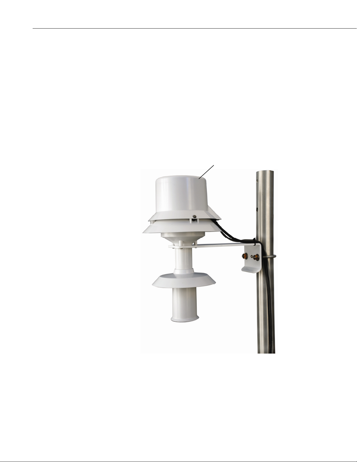
3.3 43502 Radiation Shield Installation
The 43502 mounting bracket has a U-bolt configured for attaching the shield to
a vertical tripod mast or tower leg up to 2” in diameter. By moving the U-bolt
to the other set of holes the bracket can be attached to a CM200 series
crossarm, e.g. the CM204. The CM204 crossarm includes the CM210
Mounting Kit for attaching the crossarm to a tripod mast or tower leg. For
triangular towers (e.g. the UT30), an additional PN CM210 Crossarm
Mounting Kit can be ordered for attaching the crossarm to two tower legs for
additional stability.
Attach the 43502 to the tripod/tower or crossarm using the U-bolt. Tighten the
U-bolt sufficiently for a secure hold without distorting the plastic v-block. See
the drawings in Appendix B for reference to names and locations of shield
components and position of sensor within the shield.
The blower cover is hinged to allow easy access for sensor installation and
cable connections. Loosen the captive screw in the blower cover to open. The
junction box provides terminals for cable connections and properly positions
the sensor within the shield assembly.
With the blower cover open connect blower power (12-14 VDC) to the
terminals on the underside of the cover (Figure B-2). Terminal designations
positive (POS), negative (NEG), and optional tachometer (TACH), are marked
on the printed circuit board. Blower power is normally provided by the plug-in
3
Page 8
43347 RTD Temperature Probe and 43502 Aspirated Radiation Shield
power supply adapter included. BE SURE TO OBSERVE CORRECT
POLARITY. Red is positive, black is negative. The blower motor draws
approximately 420mA-480mA. Use sufficiently heavy gauge wire between
the power supply adapter and the blower motor terminals to avoid significant
voltage drop. Clamp the blower power cable with the cable clamp provided at
the edge of the printed circuit card. When tying the cable to the mounting
structure provide a sufficient loop in the cable to allow the blower cover to be
opened and closed easily.
Install the 43347 probe inside the 43502 shield using the sensor mounting
bushing (supplied with the 43502) as shown in Figure B-1. The sensor cable
exits the side of the blower housing at the notches provided using the black
grommet to provide a seal (Figure B-3). Clamp the cable to the lower flange
of the housing to keep it in proper position when the cover is closed. Route the
sensor cable to the instrument enclosure. Secure the cable to the tripod/tower
using cable ties.
43502 Shield
4
FIGURE 3-1. 43502 Radiation Shield Mounted to Tripod Mast
Page 9
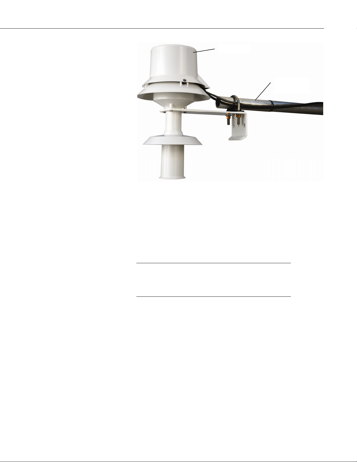
43347 RTD Temperature Probe and 43502 Aspirated Radiation Shield
43502 Shield
CM200 Series
Crossarm
FIGURE 3-2. 43502 Radiation Shield Mounted to a
CM200 Series Crossarm
3.4 41003-5 Radiation Shield Installation
The 41003-5 Radiation shield has a U-bolt for attaching the shield to tripod
mast / tower leg (Figure 3-3), or CM200 series crossarm. The radiation shield
ships with the U-bolt configured for attaching the shield to a vertical pipe.
Move the U-bolt to the other set of holes to attach the shield it to a crossarm.
NOTE
The split nut that ships with the 41003-5 shield must be replaced
with split nut PN 27251 (which must be ordered separately),
which has a slightly larger diameter to accommodate the 43347
probe.
Loosen the split-nut on the bottom plate of the 41003-5, and insert the 43347
into the shield. Tighten the split-nut to secure the sensor in the shield. Route
the sensor cable to the instrument enclosure. Secure the cable to the
tripod/tower using cable ties.
5
Page 10
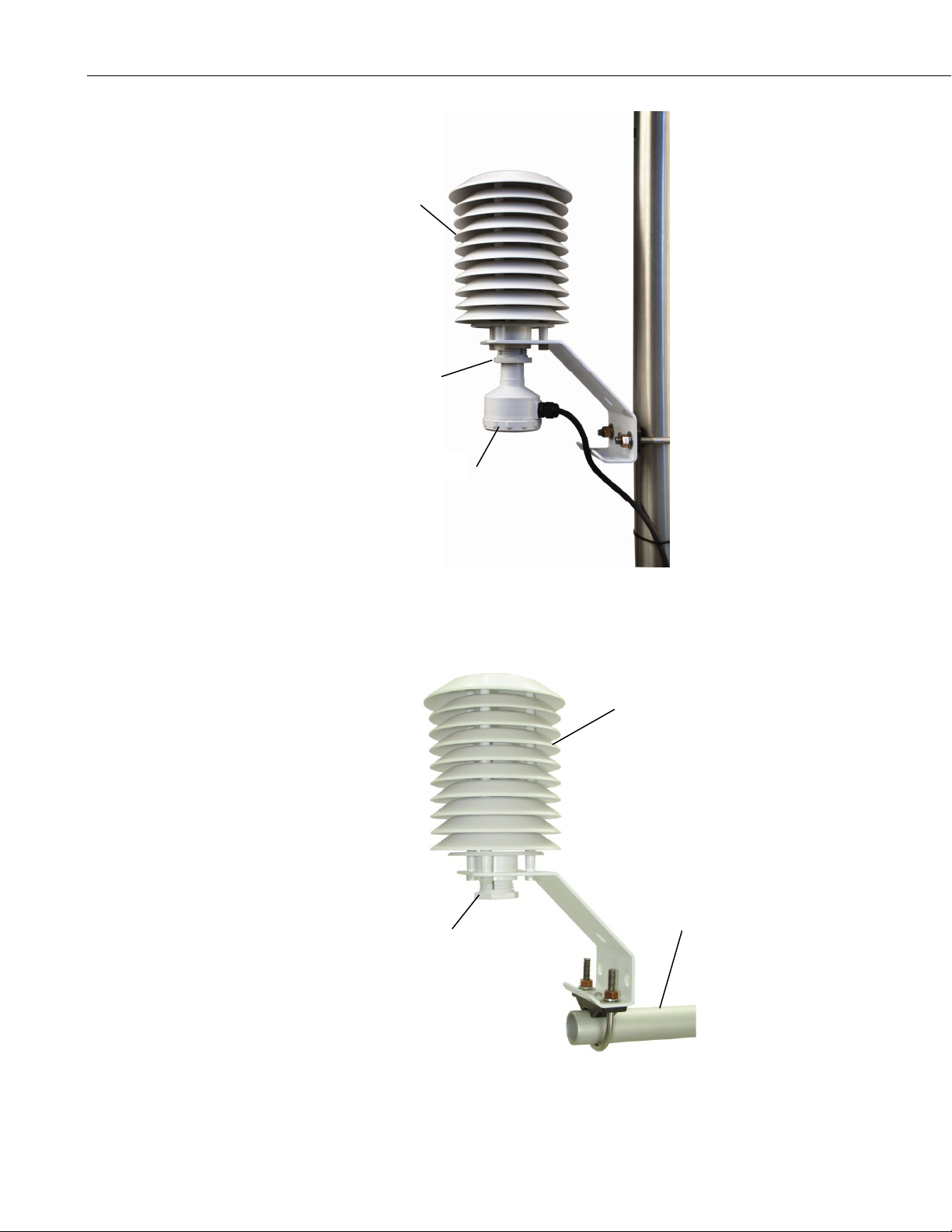
43347 RTD Temperature Probe and 43502 Aspirated Radiation Shield
41003-5 Shield
PN 27251 Split Nut
43347 Probe
FIGURE 3-3. 41003-5 Radiation Shield Mounted to Tripod Mast
41003-5 Shield
PN 27251 Split Nut
CM200 Series
Crossarm
6
FIGURE 3-4. 41003-5 Radiation Shield Mounted to a
CM200 Series Crossarm
Page 11
4. Wiring
4.1 43347-VX Temperature Probe Wiring
43347 RTD Temperature Probe and 43502 Aspirated Radiation Shield
The 43347 comes in two versions—the “IX” version and the “VX” version.
The “IX” version connects to dataloggers that can issue current excitation
(CR3000, CR5000 only). The “VX” version can connect directly to
dataloggers that only have voltage excitation (e.g., CR10(X), CR800,
CR1000).
43347 probes with the –VX option are wired to the datalogger as described in
Section 4. 43347 probes with the –IX option are wired to the CR3000 or
CR5000 dataloggers as described in Section 6.
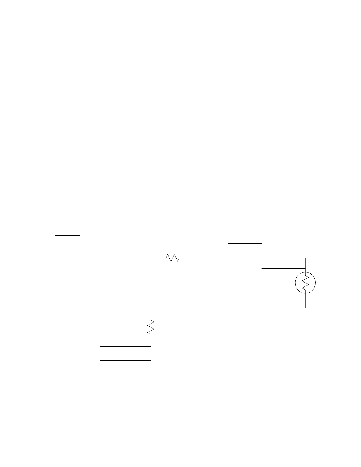
The 43347-VX probe is configured as a four wire half bridge as shown in
Figure 3-3. Each probe requires two differential inputs and one voltage
excitation channel (one excitation channel can be used for two probes). The
black and orange wires connect to the first of two contiguous input channels.
For example, if channels 1 and 2 are used, the black and orange wires connect
to 1H and 1L respectively, and the white and green wires connect to 2H and 2L
respectively.
Connections to Campbell Scientific dataloggers are given in Table 4-1. When
Short Cut software is used to create the datalogger program, wire the sensor to
the channels shown on the wiring diagram created by Short Cut.
Wire Label
Shield CLEAR
Shield G
+ RTD RED
Volt Excite/+ RTD
+ Sense WHITE
Sense Signal
- Sense GREEN
Signal Ref
- RTD BLACK
RTD/Signal/- RTD
RTD Signal Ref
Reference Low ORANGE
Ex
citation Return PURPLE
Reference
10K 1%
1000 OHM
0.01% 3PPM/C
R
f
43347
Terminals
EARTH GND
+ RTD
+ SENSE
- SENSE
- RTD
1000 OHM
RTD
R
s
FIGURE 4-1. 43347-VX Temperature Probe Wiring
7
Page 12
43347 RTD Temperature Probe and 43502 Aspirated Radiation Shield
TABLE 4-1. Datalogger Connections
Color
Wire Label
CR10(X), CR510
CR3000, CR1000, CR800, CR5000,
CR23X, 21X, CR7
Red Volt Excite/+ RTD Switched Excitation Switched Excitation
White Sense Signal Differential (high) Differential (high)
Green Sense Signal Ref Differential (low) Differential (low)
Black RTD Signal/- RTD Differential (high) Differential (high)
Orange RTD Signal Ref Differential (low) Differential (low)
Purple Excitation Reference (AG)
Clear Shield G G
8
NOTE
FIGURE 4-2. 43502 Aspirated Radiation Shield Wiring
Occasionally, a customer may need to connect an “IX” version
of the sensor to a datalogger that has voltage excitation only
(e.g., CR10(X), CR800, CR1000). The customer can do this by
using a 4WPB1K terminal input module (refer to the 4WPB1K
manual for more information).
Page 13

43347 RTD Temperature Probe and 43502 Aspirated Radiation Shield
4.2 43502 Aspirated Radiation Shield Wiring
The shield includes a 12 VDC transformer that plugs into 110 VAC. In most
applications AC power is run to the tower or tripod and terminated in a
junction box that is large enough to house the transformer(s).
Connect the red and black wires from the shield cable to the terminal block and
transformer as shown in Figure 4-2.
5. Datalogger Programming for the 43347-VX Probe
This section is for users who write their own datalogger programs. A
datalogger program to measure this sensor can be created using Campbell
Scientific’s Short Cut Program Builder software. You do not need to read this
section to use Short Cut.
Section 4 covers the 43347-VX probe, where the –VX specifies that the
probe/cable is configured for a 4-wire half bridge measurement using an
excitation voltage. Programming examples for the 43347-IX probe are
covered in Section 6.
The 43347 temperature is measured with a four wire half-bridge measurement,
Instruction BRHalf4W in CRBasic dataloggers, or Instruction 9 in Edlog
dataloggers. The measurement applies an excitation voltage and makes two
differential voltage measurements. The first measurement is made across the
fixed resistor (Rf), the second is made across the RTD (Rs). The result is the
ratio of the two resistances (Rs/Rf), which is not affected by lead length.
The result from the measurement is converted to temperature by a custom
polynomial for calibrated temperature probes (Section 5.1), or the standard PRT
resistance to temperature conversion for uncalibrated temperature probes (Section
5.2).
Table 5-1 shows the sensor wiring for the measurement examples Sections 5.1 and
5.2.
TABLE 5-1. Wiring for Measurement Examples
Color
Clear Shield (G) for CR10(X)
Red Switched Excitation E1
Function
Datalogger Channels
used for
Measurement
Examples
White Differential High 2H
Green Differential Low 2L
Black Differential High 1H
Orange Differential Low 1L
Purple Analog Reference (AG) for CR10(X)
9
Page 14

43347 RTD Temperature Probe and 43502 Aspirated Radiation Shield
5.1 Programming for Calibrated 43347-VX Probes
Calibrated 43347 probes are provided with a calibration certificate from R.M.
Young Co. that gives the relationship of resistance to temperature (°C) as
Equation “T”.
T = -250.052585 + R x 2.375187E-1 + R
The measurement result of the instruction with a multiplier of 1.0 and an offset
of 0.0 is R
5.1.1 CR1000 Example for Calibrated 43347-VX Probes
Because the calibration coefficients are to convert sensor resistance (Rs) to
temperature, the BrHalf4W measurement result (Rs/Rf) must be multiplied by
1000 (Rf), before the coefficients are applied.
'CR1000
'Declare Variables and Units
Public RTD_Res
Public RTD_Cal_C
Units RTD_Cal_C = Deg C
'Define Data Tables
DataTable(Table1,True,-1)
DataInterval(0,60,Min,10)
Average(1,RTD_C,FP2,False)
EndTable
'Main Program
BeginProg
Scan(5,Sec,1,0)
'Measure 43347 (calibrated) probe and convert Rs/Rf to Rs
BrHalf4W(RTD_Res,1,mV250,mV250,1,1,1,2500,True,True,0,_60Hz,1000,0)
'Apply calibration coefficients (probe specific)
'43347 calibration T=-250.052585+(R*2.375187e-1)+(R^2*1.258482e-5)
RTD_Cal_C = -250.052585+(RTD_Res*2.375187e- 1)+((RTD_Res^2)* 1.258482e-5)
'Call Data Tables and Store Data
CallTable(Table1)
NextScan
EndProg
= the RTD resistance divided by 1000.
s/Rf
2
x 1.258482E-5
10
Page 15

43347 RTD Temperature Probe and 43502 Aspirated Radiation Shield
5.1.2 CR10X Example for Calibrated 43347-VX Probes
Because the Full Bridge w/mv Excit (P9) resistance is divided by 1000, the
coefficients given in Equation “T” can be entered into the polynomial without
exponents. C0 is entered as given, C1 is divided by .001, and C2 is divided by
.000001. For example:
Equation “T” from R.M. Young’s RTD Calibration Report
:
T= -250.052585
+Rx 2.375187E-01
+R
2
1.258482E-05
Scaled coefficients to be entered into Instruction 55:
C0 = -250.05
C1 = 237.52
C2 = 12.585
;{CR10X}
;
*Table 1 Program
01: 5 Execution Interval (seconds)
;Measure the 43347 probe, result = Rs/Rf
1: Full Bridge w/mv Excit (P9)
1: 1 Reps
2: 24 250 mV 60 Hz Rejection Ex Range ;CR23X (200 mV); 21X,CR7 (500 mV)
3: 24 250 mV 60 Hz Rejection Br Range ;CR23X (200 mV); 21X,CR7 (500 mV)
4: 1 DIFF Channel
5: 1 Excite all reps w/Exchan 1
6: 2500 mV Excitation ;CR23X (2000 mV); 21X,CR7 (5000 mV)
7: 1 Loc [ RTD_C ]
8: 1 Mult
9: 0 Offset
;Apply calibration coefficients (probe specific)
;43347 Calibration T = -250.052585,+(R*2.375187e-1)+(R^2*1.258482e-5)
2: Polynomial (P55)
1: 1 Reps
2: 1 X Loc [ RTD_C ]
3: 1 F(X) Loc [ RTD_C ]
4: -250.05 C0 ;Coefficients will differ for each probe
5: 237.52 C1
6: 12.585 C2
7: 0.0 C3
8: 0.0 C4
9: 0.0 C5
11
Page 16

43347 RTD Temperature Probe and 43502 Aspirated Radiation Shield
5.2 Programming for Uncalibrated 43347-VX Probes
Instruction 9 applies an excitation voltage and makes two differential
measurements. A multiplier of 1.0 on the four wire half-bridge measurement
converts the measurement result to Rs/Ro (assuming Rf and Ro both equal
1000 ohms). The RTD temperature instruction converts Rs/Ro to temperature
in accordance with DIN Standard 43760. Because the alpha of the RTD used
in the temperature probe differs from DIN standard 43760, a multiplier of
1.0267 is required for Instruction 16.
5.2.1 CR1000 Example for Uncalibrated 43347-VX Probes
'CR1000
'Declare Variables
Public RTD_C
'Define Data Tables
DataTable(One_Hour,True,-1)
DataInterval(0,60,Min,0)
Sample(1,RTD_C,IEEE4)
EndTable
'Main Program
BeginProg
Scan(1,Sec,1,0)
'43347 RTD Temperature Probe (not calibrated) measurement RTD_C:
BrHalf4W(RTD_C,1,mV250,mV250,1,Vx1,1,2500,True,True,0,_60Hz,1,0)
PRT(RTD_C,1,RTD_C,1.0267,0)
'Call Data Tables and Store Data
CallTable(One_Hour)
NextScan
EndProg
12
5.2.2 CR10X Example for Uncalibrated 43347-VX Probes
;{CR10X}
;
*Table 1 Program
01: 5 Execution Interval (seconds)
;Measure the 43347 probe, result = Rs/Rf
1: Full Bridge w/mv Excit (P9)
1: 1 Reps
2: 24 250 mV 60 Hz Rejection Ex Range ;CR23X (200 mV); 21X,CR7 (500 mV)
3: 24 250 mV 60 Hz Rejection Br Range ;CR23X (200 mV); 21X,CR7 (500 mV)
4: 1 DIFF Channel
5: 1 Excite all reps w/Exchan 1
6: 2500 mV Excitation ;CR23X (2000 mV); 21X,CR7 (5000 mV)
7: 1 Loc [ RTD_C ]
8: 1 Mult
9: 0 Offset
Page 17

43347 RTD Temperature Probe and 43502 Aspirated Radiation Shield
;Convert measurement result to Temperature deg C
2: Temperature RTD (P16)
1: 1 Reps
2: 1 R/R0 Loc [ RTD_C ]
3: 1 Loc [ RTD_C ]
4: 1.0267 Mult ; (0.00385/0.00375)
5: 0 Offset
6. 43347-IX Measurement using Current Excitation
The 43347-IX probe is measured with the Resistance measurement instruction
with the CR3000 and CR5000 dataloggers. The Resistance measurement
applies a switched current excitation and measures the voltage across the 1000
ohm RTD. Appendix D shows how a single current excitation channel can be
used to excite as many as 25 43347 probes connected in series if the excitation
current is 170 μA. Details on determining the excitation current and other
parameter options are described in Section 6.3.
6.1 Wiring
Wire Label
Ground
Current Excite/+ RTD
Sense Signal
Sense Signal Ref
Current Return/- RTD
Function
Shield CLEAR
+ RTD RED
+ Sense WHITE
- Sense GREEN
- RTD BLACK
The 43347-IX probe is configured as shown in Figure 6-1. Connections to the
CR3000 and CR5000 dataloggers are shown in Table 6-1.
When Short Cut software is used to create the datalogger program, wire the
sensor to the channels shown on the wiring diagram created by Short Cut.
43347
Terminals
EARTH GND
+ RTD
+ SENSE
- SENSE
- RTD
FIGURE 6-1. 43347-IX Temperature Probe Schematic
1000 OHM
RTD
R
s
13
Page 18

43347 RTD Temperature Probe and 43502 Aspirated Radiation Shield
TABLE 6-1. Datalogger Connections
Color Wire Label CR3000, CR5000
Red Current Excite/
+ RTD
White Sense Signal Differential (high)
Green Sense Signal Ref Differential (low)
Black Current Return/
- RTD
Clear Ground Ground ( )
NOTE
Occasionally, a customer may need to connect an “IX” version
of the sensor to a datalogger that has voltage excitation only
(e.g., CR10(X), CR800, CR1000). The customer can do this by
using a 4WPB1K terminal input module (refer to the 4WPB1K
manual for more information).
6.2 Datalogger Programming
This section is for users who write their own programs. A datalogger program
to measure this sensor can be created using Campbell Scientifics’ Short Cut
Program Builder software. You do not need to read this section to use Short
Cut.
Switched Current Excitation
Switched Current Excitation Return
The 43347-IX is measured with the Resistance measurement instruction with
the CR3000 and CR5000 dataloggers. The Resistance measurement applies a
switched current excitation and measures the voltage across the 1000 ohm
RTD. The result, with a multiplier of 1 and an offset of 0, is the RTD
resistance in ohms. The measurement result is converted to temperature with
the PRT instruction for uncalibrated probes, or with a polynomial equation for
calibrated probes. Calibrated probes include a calibration certificate with the
polynomial coefficients.
The Resistance and PRT Instructions with their parameters are listed below:
Resistance(Dest, Reps, Range, DiffChan, IexChan, MeasPEx, EXuA, RevEx,
RevDiff, SettlingTime, Integ, Mult, Offset)
PRT(Dest, Reps, Source, Mult, Offset)
Table 6-2 shows the sensor wiring for the measurement examples.
14
Page 19

43347 RTD Temperature Probe and 43502 Aspirated Radiation Shield
TABLE 6-2. Wiring for Measurement Examples
Color Function CR3000, CR5000
Red Switched Current Excitation IX1
White Differential High 1H
Green Differential Low 1L
Black Excitation Return IXR
Clear Shield
6.2.1 Datalogger Programming for Calibrated 43347–IX Probes
Calibrated 43347-IX probes are provided with a calibration certificate that
gives the relationship of resistance to temperature as Equation “T”, as shown in
the example below:
2
T = -250.052585 + R x 2.375187E-1 + R
The measurement result of the Resistance instruction (ohms) is converted to
temperature with a polynomial equation and the coefficients from equation
“T”, as shown below.
The following example program measures a calibrated 43347-IX probe every 1
second and stores a 15 minute average temperature in degrees Celsius.
'CR3000
‘Declare Variables and Units
Public RTD_Res
Public RTD_Cal_C
'Define Data Tables
DataTable(PRT_Data,1,1000)
DataInterval(0,15,Min,1)
Average (1,RTD_Cal_C,IEEE4,False)
Endtable
'Main Program
BeginProg
Scan(1,Sec,10,0)
'Measure the 43347-IX probe
Resistance (RTD_Res,1,mV200,1,Ix1,1,170,True,True,0,_60Hz,1,0)
‘Convert RTD resistance to temperature
'43347 calibration T=-250.052585+(R*2.375187e-1)+(R^2*1.258482e-5)
RTD_Cal_C = -250.052585+(RTD_Res*2.375187e- 1)+((RTD_Res^2)* 1.258482e-5)
x 1.258482E-5
15
Page 20

43347 RTD Temperature Probe and 43502 Aspirated Radiation Shield
CallTable PRT_Data
Next Scan
EndProg
6.2.2 Datalogger Programming for Uncalibrated 43347-IX Probes
The measurement result of the Resistance instruction with a multiplier of 1.0
and an offset of 0.0 is the RTD resistance in ohms. For uncalibrated probes, the
PRT instruction is used to convert the ratio Rs/Ro to temperature in accordance
with DIN Standard 43760, where Rs is the measured resistance of the RTD,
and Ro is the resistance of the RTD at 0 degrees C (1000 ohms). Because the
alpha of the 43347 is 0.00375 and the alpha of DIN standard is 0.00385, a
multiplier of 1.0267 (0.00385/0.00375) is required in the PRT instruction.
The PRT Instruction with its parameters is listed below:
PRT( Dest, Reps, Source, Mult, Offset )
The following example program measures an uncalibrated 43347-IX probe
every 1 second and stores a 15 minute average temperature in degrees Celsius.
'CR3000
‘Declare Variables and Units
Public RTD_Res
Public RTD_RsRo
Public RTD_C
Const RTD_Ro = 1000.00 'This is the actual RTD resistance for this sensor at 0.0°C
'Define Data Tables
DataTable(PRT_Data,1,1000)
DataInterval(0,10,Min,1)
Average (1,RTD_C,IEEE4,False)
Endtable
'Main Program
BeginProg
Scan(3,Sec,10,0)
'Measure the 43347-IX Probe
Resistance (RTD_Res,1,mV200,1,Ix1,1,170,True,True,0,_60Hz,1,0)
‘Convert RTD resistance to temperature
RTD_RsRo = (RTD_Res / RTD_Ro)
PRT (RTD_C,1,RTD_RsRo,1.0267,0.0)
CallTable PRT_Data
Next Scan
EndProg
16
Page 21

43347 RTD Temperature Probe and 43502 Aspirated Radiation Shield
6.3 Resistance Measurement Instruction Details
The Resistance instruction applies a switched current excitation to the 43347
probe, and makes two differential voltage measurements. The first differential
voltage measurement is made across the RTD; the second is made across a
precision 1000 Ω resistor in the CR3000 current excitation circuitry. The
measurement result (X) = Vs/Ix = RTD resistance in ohms, where Vs is the
measured voltage and Ix is the excitation current.
The maximum excitation current is ±2.5 mA. The parameters for the
excitation current, measurement range, differential channel, and options to
reverse the excitation current and switch the differential inputs are
configurable, as discussed in the following sections.
6.3.1 Determining the Excitation Current
Current passing through the RTD causes heating within the RTD, which is
referred to as “self-heating”, resulting in a measurement error. To minimize
self-heating errors, use the minimum current that will still give the desired
resolution. The best resolution is obtained when the excitation is large enough
to cause the signal voltage to fill the measurement range.
The following example determines an excitation current that keeps self-heating
effects below 0.002°C in still air.
Self heating can be expressed as
ΔT = (Ix2R
Where: ΔT = self heating in °C
Ix = current excitation
Solving the above equation for Ix:
Ix = (ΔT / R
To keep self-heating errors below 0.002 °C, the maximum current Ix is:
Ix = (.002 °C / (1000 Ω *.05 °C / .001W)) ^1/2
Ix = 200uA
The best resolution is obtained when the excitation is large enough to cause the
signal voltage to fill the measurement full scale range (the possible ranges are
+/- 5000, 1000, 200, 50 and 20mV).
RRTD = 1000 Ω RTD resistance
θ = 0.05°C/mW self heating coefficient
RTD
) θ
RTD
θ)^1/2
17
Page 22

43347 RTD Temperature Probe and 43502 Aspirated Radiation Shield
The maximum voltage would be at the high temperature or highest resistance
of the RTD. At +40°C, a 1000 Ω RTD with α = 3.75 Ω/°C is about 1150
ohms.
Using Ohm's law to determine the voltage across the RTD at 40°C.
V = Ix R
Using an Ix value of 200uA, the voltage is:
V = 200uA * 1150 ohms
V= 230mV
This is just over the +/- 200mV input voltage range of the CR3000.
For a maximum voltage of 200mV, the current Ix is:
Ix = 200mV/1150 ohms
Ix ~170uA
6.3.2 Reducing Measurement Noise
AC power lines, pumps, and motors can be the source of electrical noise. If
the 43347 probe or datalogger is located in an electrically noisy environment,
the measurement should be made with the 60 or 50 Hz rejection options.
Offsets in the measurement circuitry may be reduced by reversing the current
excitation (RevEx), and reversing the differential analog inputs (RevDiff), as
shown in the program examples in Sections 6.2.
7. Maintenance
Inspect and clean the shield and probe periodically to maintain optimum
performance. When the shield becomes coated with a film of dirt, wash it with
mild soap and warm water. Use alcohol to remove oil film. Do not use any
other solvent. Check mounting bolts periodically for possible loosening due to
tower vibration.
8. 43347 RTD Temperature Probe Calibration
Calibration should be checked every 12 months. Probes used to measure a
temperature gradient should be checked with respect to absolute temperature,
and with respect to zero temperature difference. An excellent discussion on
calibration procedures can be found in the Quality Assurance Handbook for
Air Pollution Measurement Systems, Volume IV Meteorological
Measurements
1
.
9. Manufacturer's Information
Refer to the RM Young 43502 Instruction Manual for additional information
such as replacement parts, assembly drawings, and electrical schematics.
18
Page 23

43347 RTD Temperature Probe and 43502 Aspirated Radiation Shield
10. Troubleshooting
-99999, NAN displayed in input location:
Make sure the temperature probe is connected to the correct input
channels (Sections 5 and 6). The input channel (Instruction 9) refers to
the channel that the black and orange wires are connected to. The white
and green wires connect to the next (higher) contiguous channel.
Unreasonable value displayed in input location:
Make sure the multiplier and offset values entered for Instruction 9 are
correct. For calibrated temperature probes (Section 6.1), make sure the
coefficients have been properly scaled and entered for Instruction 55. For
uncalibrated temperature probes (Section 6.2), make sure the multiplier
and offset values have been properly entered for Instruction 16.
Temperature reading too high:
Make sure the blower is working properly and there are no obstructions to
the air flow in the sensor shield, telescoping arm, or vent holes. Also,
check that the probe end of the shield points toward the prevailing wind.
11. References
1
EPA, (1989). Quality Assurance Handbook for Air Pollution Measurement
Systems Volume IV - Meteorological Measurements, EPA Office of Research
and Development, Research Triangle Park, North Carolina 27711.
19
Page 24

43347 RTD Temperature Probe and 43502 Aspirated Radiation Shield
20
Page 25

Appendix A. Example CR10(X) Program for Ice Bath Calibration
The following program can be used to calibrate 43347 probes (probes ordered
without the 3-point RM Young calibration) for users wanting better than ±0.3
°C. The calibration computes a multiplier for the P9 measurement Instruction
(Section 5.2).
Procedure:
Immerse the stainless steel tip of the 43347 probe in a properly prepared ice
1
bath
and allow the temperature to stabilize (about an hour). Program the
CR10X with the program listed below. Toggle Flag 1 high, which causes the
43347 probe to be measured 100 times. The average of the measurement result
is placed into input location 2 and the reciprocal of location 2 is placed into
input location 3. The value from location 3 is used as the multiplier for the P9
Instruction (Section 5.2). Typical values for locations 2 and 3 would be 1.0012
and 0.998 respectively.
;{CR10X}
;
*Table 1 Program
01: 1 Execution Interval (seconds)
1: If Flag/Port (P91)
1: 21 Do if Flag 1 is Low
2: 0 Go to end of Program Table
2: Z=F (P30)
1: 0 F
2: 0 Exponent of 10
3: 1 Z Loc [ counter ]
3: Beginning of Loop (P87)
1: 1 Delay
2: 100 Loop Count
4: Full Bridge w/mv Excit (P9)
1: 1 Reps
2: 24 250 mV 60 Hz Rejection Ex Range
3: 24 250 mV 60 Hz Rejection Br Range
4: 1 DIFF Channel
5: 1 Excite all reps w/Exchan 1
6: 2500 mV Excitation
7: 2 Loc [ result ]
8: 1.0 Mult
9: 0 Offset
5: Z=Z+1 (P32)
1: 1 Z Loc [ counter ]
A-1
Page 26

Appendix A. Example CR10(X) Program for Ice Bath Calibration
6: If (X<=>F) (P89)
1: 3 X Loc [ P9_mult ]
2: 3 >=
3: 100 F
4: 30 Then Do
7: Do (P86)
1: 10 Set Output Flag High (Flag 0)
8: Do (P86)
1: 21 Set Flag 1 Low
9: End (P95)
10: Set Active Storage Area (P80)
1: 3 Input Storage Area
2: 2 Loc [ result ]
11: Average (P71)
1: 1 Reps
2: 2 Loc [ result ]
12: Z=1/X (P42)
1: 2 X Loc [ result ]
2: 3 Z Loc [ P9_mult ]
13: End (P95)
A-2
Page 27

Appendix B. 43502 Aspirated Radiation
JMT
A
08/06
08/06
SECTION VIEW
MODEL 43502 ASPIRATED RADIATION SHIELD
DWN
CHK
DWG
R.M. YOUNG CO. TRAVERSE CITY, MI 49686 U.S.A. 231-946-3980
PRD
DWN
41382 TEMP/RH PROBE CONFIGURATION
43502 with 41382 TEMP/RH PROBE
S43502(pg3)(A)
43447-01 12VDC BLOWER
41382 TEMP/RH PROBE
43532 MOTOR CONNECTION
P.C. BOARD
BLOWER CABLE CLAMP
SENSOR CABLE CLAMP
43530 SHIELD ASSEMBLY
43534 SENSOR MTG BUSHING
BLOWER MOTOR
BLK RED
TACHOMETER OUTPUT
(SPECIAL ORDER ONLY)
BLOWER POWER
12-14 VDC @ 500MA
TO DATA
LOGGER
TEMP OR
TEMP R.H. SENSOR
RUBBER FLANGE
BUSHING
Shield
B-1
Page 28

Appendix B. 43502 Aspirated Radiation Shield
Sensor
Mounting
Bushing
Grommet
FIGURE B-1. 43347 Probe and Bushing
B-2
FIGURE B-2. 43502 Shield Power Connections
Page 29

Appendix B. 43502 Aspirated Radiation Shield
FIGURE B-3. 43347 Probe Mounted Inside the 43502 Shield
B-3
Page 30

Appendix B. 43502 Aspirated Radiation Shield
B-4
Page 31

Appendix C. 43347 Aspirated Radiation Shield
C-1
Page 32

Appendix C. 43347 Aspirated Radiation Shield
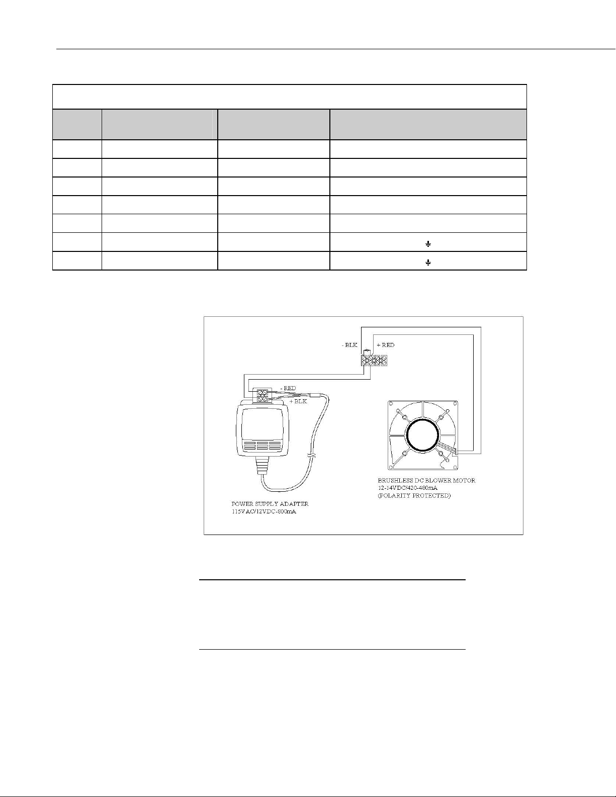
The 43408 radiation shield employs concentric downward facing intake tubes
and a small canopy shade to isolate the temperature probe from direct and
indirect radiation. The 43347 temperature probe mounts vertically in the
center of the intake tubes.
A brushless 12 VDC blower motor pulls ambient air into the shield and across
the temperature probe to reduce radiation errors. The blower operates off a
115 VAC/12 VDC transformer that is included with the shield.
C.1 Specifications
43408 ASPIRATED RADIATION SHIELD:
DIMENSIONS:
Length: 44", extendable to 75"
Diameter of Blower Housing: 6"
AIR FLOW RATE:
3 - 7 m/s depending on sensor size
TEMPERATURE RANGE: ±50° C
POWER REQUIRED:
12 - 14 VDC @ 420 - 480 mA
115 VAC/12 VDC - 800 mA transformer supplied
RADIATION ERROR:
< 0.2°C radiation @ 1100 W/m
LIFE EXPECTANCY ON BLOWER:
80,000 hrs @ 25°C
Blower Housing
FIGURE C.1-1. 43347 RTD Temperature Probe and 43408 Aspirated Radiation Shield
2
irradiance
43347 Temperature Probe
and Junction Box
43408 Aspirated
Radiation Shield
C-2
Page 33

C.2 Installation
Appendix C. 43347 Aspirated Radiation Shield
Refer to the General Assembly drawing in the RM Young 43408 Instruction
Manual (included) for reference to the names of shield components.
Thread the molded shield assembly into the appropriate threaded opening in
the shield mounting tee at the end of the telescoping arm. Hand-tighten the
shield to slightly compress the O-ring seal; do not crossthread or overtighten.
Insert the sensor mounting tube and junction box with its split bushing into the
shield mounting tee. Tighten the threaded split bushing to secure the junction
box in place; do not overtighten.
Two U-bolt brackets attach the radiation shield to horizontal, vertical, or
diagonal tower members up to 2 inches in diameter, spaced 12 to 30 inches
apart. Campbell Scientific PN 7515 10 m Aspirated Shield Mounting Bracket
can be used to mount the shield to a single vertical pipe or mast, as shown in
Figure C.2-1.
The mounting arm should be horizontal with the vent holes facing downward,
with the probe end pointing towards the prevailing wind. Tighten the U-bolt
brackets sufficiently for a secure hold without distorting the plastic v-blocks.
Loosen the band clamp and extend the arm at least 24 inches. Rotate the shield
so the intake tube is oriented vertically with the intake opening facing down.
Tighten the band clamp and secure the sensor lead to the arm using UV
resistant cable ties.
Vent Holes Intake Tube
FIGURE C.2-1. PN 7515 10 m Aspirated Shield Mounting Bracket
C-3
Page 34

Appendix C. 43347 Aspirated Radiation Shield
FIGURE C.2-2. 43408 Aspirated Radiation Shield Wiring
C-4
Page 35

Appendix D. Measure Two 43347-IX Probes Using One Current Excitation Channel
One current excitation channel can excite multiple 43347 probes if the
“Current Return” wire of the first probe is connected to the “Current
Excitation” wire of the second probe.
In theory, a single Ix channel can excite up to 25 of the 43347-IX probes with
170 µA if all probes are at a temperature less than or equal to 45°C (see
Section 6). At 45°C, the 43347 has a resistance of ~1175 ohms. The
resistance increases as more probes are connected in series. The increase of
resistance requires the Ix channel to raise the driving voltage to maintain the
same current. The maximum voltage the Ix channel can drive is ±5 Vdc.
Therefore, the maximum number of 43347 probes is:
Max. voltage/(current * resistance per probe at 45°C)
5 volts/(0.00017 amps * 1175 ohms) = 25
The CR3000’s differential channel count limits the number of probes to 14
without a multiplexer.
One disadvantage to driving multiple probes with a single Ix channel is that if
one probe shorts or opens then the measurements of all the probes on that Ix
channel will be bad. If, for example, there are two probes at each of three
levels, it might be best to drive one probe from each level on one Ix and then
drive the remaining probes on a second Ix. This creates separate A and B
systems, which allow maintenance to be done on one system while the other
system continues to make good measurements.
D-1
Page 36

Appendix D. Measure Two 43347-IX Probes Using One Current Excitation Channel
D.1 Wiring
Wiring for two 43347-IX probes is shown in Figure D-1.
Wire Label
Ground CLEAR
Cur rent Ex cite/+ RTD RED
Sense Signal WHITE
Sense Signal Ref GREEN
BLACK
Ground CLEAR
RED
Sense Signal WHITE
Sense Signal Ref GREEN
Current Return/- RTD BLACK
43347
Terminals
EARTH GND
+ RTD
+ SENSE
- SENSE
- RTD
43347
Terminals
EARTH GND
+ RTD
+ SENSE
- SENSE
- RTD
1000 OHM
RTD
1000 OHM
RTD
#1
R
s
#2
R
s
FIGURE D-1. Schematic for Two 43347-IX Temperature Probes
D.2 Example Program for two Calibrated 43347-IX
Probes
This section includes an example CR3000 program that measures two
calibrated 43347-IX probes. A CR5000 is programmed similarly. Wiring for
the example program is shown in Table D-1.
D-2
Page 37

Appendix D. Measure Two 43347-IX Probes Using One Current Excitation Channel
TABLE D-1. Wiring for Two 43347-IX Probes Example
Color Function CR3000, CR5000
Probe #1
Red Switched Current Excitation IX1
White Differential High 1H
Green Differential Low 1L
Black Excitation Return Red of Probe #2
Clear Shield
Probe #2
Red Switched Current Excitation Black of Probe #1
White Differential High 2H
Green Differential Low 2L
Black Excitation Return IXR
Clear Shield
'CR3000 Series Datalogger
'Declare Variables and Units
Public RTD1_Res, RTD1_Cal_C
Public RTD2_Res, RTD2_Cal_C
'Define Data Tables
DataTable (PRT_Data,1,1000)
DataInterval (0,15,Min,1)
Average(1,RTD1_Cal_C,IEEE4,False)
Average(1,RTD2_Cal_C,IEEE4,False)
EndTable
'Main Program
BeginProg
Scan (1,Sec,0,0)
'Measure the 43347-IX probes
Resistance(RTD1_Res,1,mV200,1,Ix1,1,170,True,True,0,_60Hz,1,0)
Resistance(RTD2_Res,1,mV200,2,Ix1,1,170,True,True,0,_60Hz,1,0)
'Convert RTD resistance to temperature
'43347 #1 calibration T=-250.052585+(R*2.375187e-1)+(R^2*1.258482e-5)
RTD1_Cal_C = -250.052585+(RTD1_Res*2.375187e-1)+((RTD1_Res^2)*1.258482e-5)
'43347 #2 calibration T=-250.152585+(R*2.475187e-1)+(R^2*1.358482e-5)
RTD2_Cal_C = -250.152585+(RTD1_Res*2.475187e-1)+((RTD1_Res^2)*1.358482e-5)
CallTable PRT_Data
NextScan
EndProg
D-3
Page 38

Appendix D. Measure Two 43347-IX Probes Using One Current Excitation Channel
D-4
Page 39

Page 40

Campbell Scientific Companies
Campbell Scientific, Inc. (CSI)
815 West 1800 North
Logan, Utah 84321
UNITED STATES
www.campbellsci.com • info@campbellsci.com
Campbell Scientific Africa Pty. Ltd. (CSAf)
PO Box 2450
Somerset West 7129
SOUTH AFRICA
www.csafrica.co.za • cleroux@csafrica.co.za
Campbell Scientific Australia Pty. Ltd. (CSA)
PO Box 444
Thuringowa Central
QLD 4812 AUSTRALIA
www.campbellsci.com.au • info@campbellsci.com.au
Campbell Scientific do Brazil Ltda. (CSB)
Rua Luisa Crapsi Orsi, 15 Butantã
CEP: 005543-000 São Paulo SP BRAZIL
www.campbellsci.com.br • suporte@campbellsci.com.br
Campbell Scientific Canada Corp. (CSC)
11564 - 149th Street NW
Edmonton, Alberta T5M 1W7
CANADA
www.campbellsci.ca • dataloggers@campbellsci.ca
Campbell Scientific Centro Caribe S.A. (CSCC)
300 N Cementerio, Edificio Breller
Santo Domingo, Heredia 40305
COSTA RICA
www.campbellsci.cc • info@campbellsci.cc
Campbell Scientific Ltd. (CSL)
Campbell Park
80 Hathern Road
Shepshed, Loughborough LE12 9GX
UNITED KINGDOM
www.campbellsci.co.uk • sales@campbellsci.co.uk
Campbell Scientific Ltd. (France)
Miniparc du Verger - Bat. H
1, rue de Terre Neuve - Les Ulis
91967 COURTABOEUF CEDEX
FRANCE
www.campbellsci.fr • info@campbellsci.fr
Campbell Scientific Spain, S. L.
Avda. Pompeu Fabra 7-9, local 1
08024 Barcelona
SPAIN
www.campbellsci.es • info@campbellsci.es
Please visit www.campbellsci.com to obtain contact information for your local US or International representative.
 Loading...