

Page 1

Model 107 Temperature Probe
Revision: 6/10
Copyright © 1983-2010
Campbell Scientific, Inc.
Page 2

Warranty and Assistance
The MODEL 107 TEMPERATURE PROBE is warranted by Campbell
Scientific, Inc. to be free from defects in materials and workmanship under
normal use and service for twelve (12) months from date of shipment unless
specified otherwise. Batteries have no warranty. Campbell Scientific, Inc.'s
obligation under this warranty is limited to repairing or replacing (at Campbell
Scientific, Inc.'s option) defective products. The customer shall assume all
costs of removing, reinstalling, and shipping defective products to Campbell
Scientific, Inc. Campbell Scientific, Inc. will return such products by surface
carrier prepaid. This warranty shall not apply to any Campbell Scientific, Inc.
products which have been subjected to modification, misuse, neglect, accidents
of nature, or shipping damage. This warranty is in lieu of all other warranties,
expressed or implied, including warranties of merchantability or fitness for a
particular purpose. Campbell Scientific, Inc. is not liable for special, indirect,
incidental, or consequential damages.
Products may not be returned without prior authorization. The following
contact information is for US and International customers residing in countries
served by Campbell Scientific, Inc. directly. Affiliate companies handle
repairs for customers within their territories. Please visit
www.campbellsci.com to determine which Campbell Scientific company
serves your country.
To obtain a Returned Materials Authorization (RMA), contact Campbell
Scientific, Inc., phone (435) 753-2342. After an applications engineer
determines the nature of the problem, an RMA number will be issued. Please
write this number clearly on the outside of the shipping container. Campbell
Scientific's shipping address is:
CAMPBELL SCIENTIFIC, INC.
RMA#_____
815 West 1800 North
Logan, Utah 84321-1784
For all returns, the customer must fill out a “Declaration of Hazardous Material
and Decontamination” form and comply with the requirements specified in it.
The form is available from our website at
completed form must be either emailed to repair@campbellsci.com
435-750-9579. Campbell Scientific will not process any returns until we
receive this form. If the form is not received within three days of product
receipt or is incomplete, the product will be returned to the customer at the
customer’s expense. Campbell Scientific reserves the right to refuse service on
products that were exposed to contaminants that may cause health or safety
concerns for our employees.
www.campbellsci.com/repair
. A
or faxed to
Page 3

107 Table of Contents
PDF viewers note: These page numbers refer to the printed version of this document. Use
the Adobe Acrobat® bookmarks tab for links to specific sections.
1. General .........................................................................1
1.1 Specifications............................................................................................1
2. Accuracy.......................................................................2
3. Installation....................................................................3
3.1 Air Temperature........................................................................................3
3.1.1 Siting...............................................................................................3
3.1.2 Assembly and Mounting.................................................................3
3.2 Soil Temperature ......................................................................................5
3.3 Water Temperature...................................................................................5
4. Wiring............................................................................5
5. Programming ...............................................................6
5.1 CRBasic....................................................................................................6
5.2 Edlog.........................................................................................................6
5.3 Example Programs....................................................................................6
5.3.1 Example Program for CR1000 Datalogger.....................................7
5.3.2 Example Program for CR10X Datalogger......................................7
5.4 Electrically Noisy Environments..............................................................8
5.5 Long Lead Lengths...................................................................................8
6. Measurement Details...................................................9
6.1 Therm107 Instruction...............................................................................9
6.2 Temp(107) Instruction (P11)..................................................................10
7. Maintenance and Calibration....................................12
8. Troubleshooting ........................................................12
Figures
2-1. Error Produced by Polynomial fit to Published Values...........................3
3-1. 107 and 41303-5A Radiation Shield on a Tripod Mast...........................4
3-2. 107 and 41303-5A Radiation Shield on a CM200 Series Crossarm.......4
6-1. 107 Thermistor Probe Schematic..........................................................10
i
Page 4

107 Table of Contents
Tables
1-1. Recommended Lead Lengths ................................................................. 1
2-1. Thermistor Interchangeability Specification........................................... 2
2-2. Polynomial Error for Edlog Dataloggers................................................2
4-1. Connections to Campbell Scientific Dataloggers................................... 5
5-1. Wiring for Example Programs................................................................ 6
6-1. Polynomial Coefficients ....................................................................... 10
6-2. Temperature, Resistance, and Datalogger Output................................ 11
ii
Page 5
Model 107 Temperature Probe
1. General
The 107 Temperature Probe uses a thermistor to measure temperature. The
probe is designed for measuring air/soil/water temperatures. For air
temperature, a 41303-5A radiation shield is used to mount the 107 Probe and
limit solar radiation loading. The probe is designed to be buried or submerged
in water to 50’ (21 psi).
For the –L option, the probe’s cable terminates in pigtails that connect to a
Campbell Scientific datalogger or a connector that attaches to a prewired
enclosure. For the –LC option, the probe’s cable is fitted with a connector that
attaches to an ET107, ET106, or MetData1 Weather Station. Throughout this
manual, 107 will refer to both the 107-L and 107-LC unless specified
otherwise.
Lead length for the 107-L and 107-LC is specified when the sensor is ordered.
Table 1-1 gives the recommended lead length for mounting the sensor on a
tripod or tower.
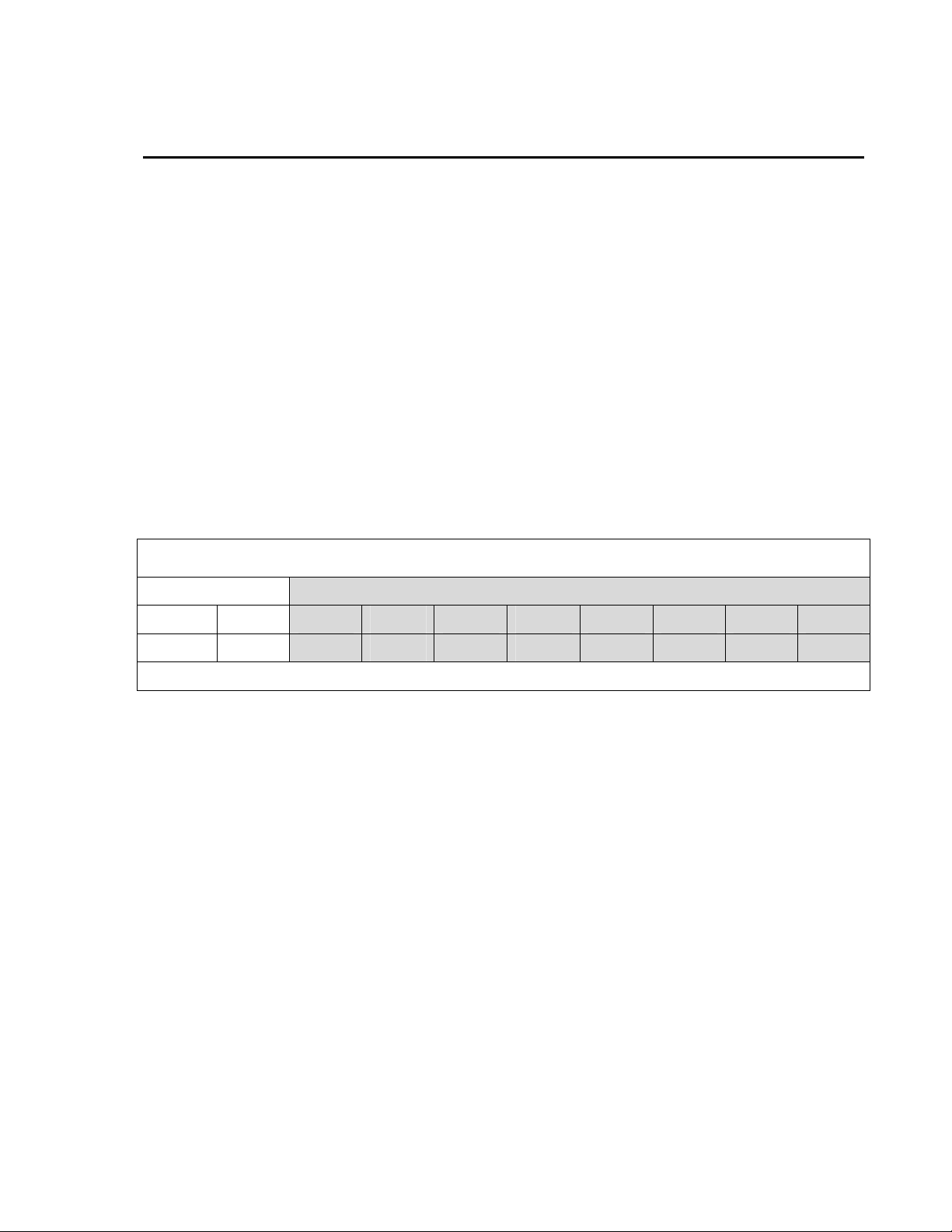
TABLE 1-1. Recommended Lead Lengths
2 m Height Atop a tripod or tower via a 2 ft crossarm such as the CM202
Mast/Leg CM202 CM6 CM10 CM110 CM115 CM120 UT10 UT20 UT30
9' 11' 11' 14' 14' 19' 24' 14' 24' 37'
Note: Add two feet to the cable length if you are mounting the enclosure on the leg base of a light-weight tripod.
The 107 ships with:
(1) Resource CD
1.1 Specifications
Sensor: BetaTherm 100K6A Thermistor
Temperature
Measurement Range: -35° to +50°C
Thermistor Interchangeability Error: Typically <±0.2°C over 0°C to 50°C; ±0.4 @ -35°C
Thermistor
Survival Range: -50°C to +100°C
Steinhart-Hart
Equation Error: ≤±0.01°C over -35° to +50°C (CRBasic dataloggers
only)
1
Page 6

Model 107 Temperature Probe
NOTE
2. Accuracy
Polynomial
Linearization Error: <±0.5°C over -35°C to +50°C (Edlog dataloggers only)
Time Constant
In Air: Between 30 and 60 seconds in a wind speed of 5 m s
Maximum L ead
Length: 1000 ft.
®
The black outer jacket of the cable is Santoprene
compound was chosen for its resistance to temperature extremes,
moisture, and UV degradation. However, this jacket will
support combustion in air. It is rated as slow burning when
tested according to U.L. 94 H.B. and will pass FMVSS302.
Local fire codes may preclude its use inside buildings.
The overall probe accuracy is a combination of the thermistor's interchangeability
specification, the precision of the bridge resistors, and the Steinhart-Hart equation
error (CRBasic dataloggers) or polynomial error (Edlog dataloggers). In a "worst
case" all errors add to an accuracy of ±0.4°C over the range of -24° to 48°C and
±0.9°C over the range of -35°C to 50°C. The major error component is the
interchangeability specification of the thermistor, tabulated in Table 2-1 . For the
range of 0° to 50°C, the interchangeability error is predominantly offset and can be
determined with a single point calibration. Compensation can then be done with an
offset entered in the measurement instruction. The bridge resistors are 0.1%
tolerance with a 10 ppm temperature coefficient. Polynomial errors are tabulated
in Table 2-2 and plotted in Figure 2-1.
rubber. This
-1
2
TABLE 2-1. Thermistor
Interchangeability Specification
Temperature (°C)
−35
−30
−20
−10
0 to +50 0.20
TABLE 2-2. Polynomial Error
for Edlog Dataloggers
-35 to +50
-24 to +48
Temperature
Tolerance (±°C)
0.40
0.40
0.32
0.25
<±0.5°C
<±0.1°C
Page 7

Model 107 Temperature Probe
FIGURE 2-1. Error Produced by Polynomial Fit to Published Values
(Edlog dataloggers only)
3. Installation
3.1 Air Temperature
3.1.1 Siting
3.1.2 Assembly and Mounting
For air temperature measurements, sensors should be located over an open
level area at least 9 m (EPA) in diameter. The surface should be covered by
short grass, or where grass does not grow, the natural earth surface. Sensors
should be located at a distance of at least four times the height of any nearby
obstruction, and at least 30 m (EPA) from large paved areas. Sensors should
be protected from thermal radiation, and adequately ventilated.
Standard air temperature measurement heights:
1.5 m +/- 1.0 m (AASC)
1.25 – 2.0 m (WMO)
2.0 m (EPA)
2.0 m and 10.0 m temperature difference (EPA)
The probe is designed to be buried or submerged in water to 50’ (21 psi).
Tools required for installing on a tripod or tower:
• 1/2” open end wrench
• small screw driver provided with datalogger
• small Phillips screw driver
• UV resistant cable ties
• small pair of diagonal-cutting pliers
3
Page 8

Model 107 Temperature Probe
The 107 must be housed inside a radiation shield when the sensor will be
exposed to solar radiation (i.e., air temperature measurements made in the
field). The 41303-5A Radiation shield has a U-bolt for attaching the shield to
tripod mast / tower leg (Figure 3-1), or CM200 series crossarm (Figure 3-2).
The radiation shield ships with the U-bolt configur ed for attaching the shield to
a vertical pipe. Move the U-bolt to the other set of holes to attach the shield to
a crossarm.
41303-5A
107
41303-5A
Tripod Mast
or Tower Leg
FIGURE 3-1. 107 and 41303-5A Radiation Shield on a Tripod Mast
Tripod Mast
or Tower Leg
107
CM200 Series Crossarm
4
FIGURE 3-2. 107 and 41303-5A Radiation Shield on a
CM200 Series Crossarm
Page 9

The 107 is held within the 41303-5A by a mounting clamp on the bottom plate
of the 41303-5A (Figure 3-2). Loosen the two mounting clamp screws, and
insert the sensor through the clamp and into the shield. Tighten the screws to
secure the sensor in the shield, and route the sensor cable to the instrument
enclosure. Secure the cable to the tripod/tower using cable ties.
3.2 Soil Temperature
The 107 is suitable for shallow burial only. It should be placed horizontally at
the desired depth to avoid thermal conduction from the surface to the
thermistor. Placement of the cable inside a rugged conduit may be advisable
for long cable runs, especially in locations subject to digging, mowing, traffic,
use of power tools, or lightning strikes.
3.3 Water Temperature
The 107 can be submerged to 50 feet. Please note that the 107 is not weighted.
Therefore, the installer should either add a weighting system or secure the
probe to a fixed or submerged object such as piling.
Model 107 Temperature Probe
4. Wiring
The connection of a 107-L to a Campbell Scientific datalogger is given in
Table 4-1. Refer to the ET107, ET106, or MetData1 manual for connecting a
107-LC to the weather station. Temperature is measured with one SingleEnded input channel and a Voltage Excitation channel. Multiple 107-L probes
can be connected to the same excitation channel (the number of probes per
excitation channel is physically limited by the number of lead wires that can be
inserted into a single excitation terminal, approximately six).
TABLE 4-1. Connections to Campbell Scientific Dataloggers
Color
Black Voltage
Description
Excitation
CR800
CR850
CR5000
CR3000
CR1000
Switched
Voltage
CR510
CR500
CR10(X)
Switched
Excitation
21X
CR7
CR23X
Switched
Excitation
Excitation
Red Temperature
Signal
Purple Signal Ground
Clear Shield
Single-Ended
Input
Single-Ended
Input
AG
G
Single-Ended
Input
5
Page 10

Model 107 Temperature Probe
5. Programming
NOTE
5.1 CRBasic
This section is for users who write their own datalogger
programs. A datalogger program to measure this sensor can be
generated using Campbell Scientific’s Short Cut Program
Builder software. You do not need to read this section to use
Short Cut.
The datalogger is programmed using either CRBasic or Edlog. Dataloggers
that use CRBasic include our CR800, CR850, CR1000, CR3000, CR5000, and
CR9000(X). Dataloggers that use Edlog include our CR510, CR10(X),
CR23X, and CR7. CRBasic and Edlog are included with LoggerNet, PC400,
and RTDAQ software.
If applicable, please read “Section 5.4—Electrically Noisy Environments” and
“Section 5.5—Long Lead Lengths” prior to programming the datalogger.
Measurement details are provided in Section 6.
The Therm107 measurement instruction is used with dataloggers that are
programmed with CRBasic to measure the 107 probe. Therm107 makes a half
bridge voltage measurement, and converts the measurement result to
temperature using the Steinhart-Hart equation. With a multiplier of 1 an d an
offset of 0, the output is temperature in degrees C. With a multiplier of 1.8 and
an offset of 32, the output is temperature in degrees F.
5.2 Edlog
The Temp(107) measurement instruction (P11) is used with dataloggers that
are programmed with Edlog to measure the 107 probe. P11 makes half bridge
voltage measurement, and converts the measurement result to temperature
using a fifth order polynomial. With a multiplier of 1 and an offset of 0, the
output is temperature in degrees C. With a multiplier of 1.8 and an offset of
32, the output is temperature in degrees F.
5.3 Example Programs
TABLE 5-1. Wiring for Example Programs
Color Description CR1000 CR10X
Black Excitation EX1 or VX1 E1
Red Signal SE1 SE1
Purple Signal Ground
Clear Shield
Both example programs measure a 107 temperature probe every second and
store a 60 minute average temperature.
AG
G
6
Page 11

5.3.1 Example Program for CR1000 Datalogger
'CR1000
'This example program measures a single 107 Thermistor probe
'once a second and stores the average temperature every 60 minutes.
'Declare the variables for the temperature measurement
Public T107_C
'Define a data table for 60 minute averages:
DataTable(Table1,True,-1)
DataInterval(0,60,Min,0)
Average(1,T107_C,IEEE4,0)
EndTable
BeginProg
Scan(1,Sec,1,0)
'Measure the temperature
Therm107(T107_C,1,1,Vx1,0,_60Hz,1.0,0.0)
'Call Data Table
CallTable(Table1)
NextScan
EndProg
Model 107 Temperature Probe
5.3.2 Example Program for CR10X Datalogger
;{CR10X}
*Table 1 Program
01: 1.0000 Execution Interval (seconds)
1: Temp (107) (P11)
1: 1 Reps
2: 1 SE Channel
3: 21 Excite all reps w/E1, 60Hz, 10ms delay
4: 1 Loc [ T107_C ]
5: 1.0 Multiplier
6: 0.0 Offset
3: If time is (P92)
1: 0 Minutes (Seconds --) into a
2: 60 Interval (same units as above)
3: 10 Set Output Flag High (Flag 0)
4: Set Active Storage Area (P80)
1: 1 Final Storage Area 1
2: 101 Array ID
5: Real Time (P77)
1: 1220 Year,Day,Hour/Minute (midnight = 2400)
6: Average (P71)
1: 1 Reps
2: 1 Loc [ T107_C ]
7
Page 12

Model 107 Temperature Probe
5.4 Electrically Noisy Environments
1: AC Half Bridge (P5)
1: 1 Reps
2: 22 7.5 mV 60 Hz Rejection Range
3: 9 SE Channel
4: 3 Excite all reps w/Exchan 3
5: 2000 mV Excitation ;Use 4000 mV on 21X and CR7
6: 1 Loc [ Air_Temp ]
7: 800 Mult
8: 0 Offset
2: Polynomial (P55)
1: 1 Reps
2: 1 X Loc [ Air_Temp ]
3: 1 F(X) Loc [ Air_Temp ]
4: -53.46 C0
5: 90.807 C1
6: -83.257 C2
7: 52.283 C3
8: -16.723 C4
9: 2.211 C5
AC power lines can be the source of electrical noise. If the datalogger is in an
electronically noisy environment, the 107 temperature measurement should be
measured with 60 Hz rejection. For CRBasic loggers, the Therm107
Integration parameter has options for 50 and 60 Hz rejection. Sixty and 50 Hz
rejection is available as an option in the Excitation Channel parameter of
Instruction 11 for the CR10X, CR510, and CR23X dataloggers. For the CR10,
CR21X and CR7, the 107 should be measured with the AC half bridge
(Instruction 5).
Example 5.4-1. CR1000 measurement instruction with 60 Hz rejection:
Therm107(T107_C,1,1,1,0,_60Hz,1.0,0.0)
Example 5.4-2. Sample CR10(X) Instructions Using AC Half Bridge
8
5.5 Long Lead Lengths
For CRBasic loggers, the 60 and 50 Hz integration options include a 3 ms
settling time; longer settling times can be entered into the Settling Time
parameter. The 60 and 50 Hz rejection options for the CR10X, CR510, and
CR23X include a delay to accommodate long lead lengths. For the CR10,
21X, and CR7, if the 107 has lead lengths of more than 300 feet, use the DC
Half Bridge instruction (Instruction 4) with a 20 millisecond delay to measure
temperature.
The delay provides a longer settling time before the measurement is made. Do
not use the 107 with long lead lengths in an electrically noisy environment.
Page 13

Model 107 Temperature Probe
Example 5.5-1. CR1000 measurement instruction with 20 mSec (20000
µSec) delay:
Therm107(T107_C,1,1,1,20000,_60Hz,1.0,0.0)
Example 5.5-2. CR10X Measurement Instructions Using DC Half Bridge
with Delay
1: Excite-Delay (SE) (P4)
1: 1 Reps
2: 2 7.5 mV Slow Range
3: 9 SE Channel
4: 3 Excite all reps w/Exchan 3
5: 2 Delay (units 0.01 sec)
6: 2000 mV Excitation ;Use 4000 mV on 21X and CR7
7: 1 Loc [ Air_Temp ]
8: .4 Mult ;Use 0.2 on 21X and CR7
9: 0 Offset
2: Polynomial (P55)
1: 1 Reps
2: 1 X Loc [ Air_Temp ]
3: 1 F(X) Loc [ Air_Temp ]
4: -53.46 C0
5: 90.807 C1
6: -83.257 C2
7: 52.283 C3
8: -16.723 C4
9: 2.211 C5
6. Measurement Details
Understanding the details in this section are not necessary for general
operation of the 107 Probe with CSI's dataloggers.
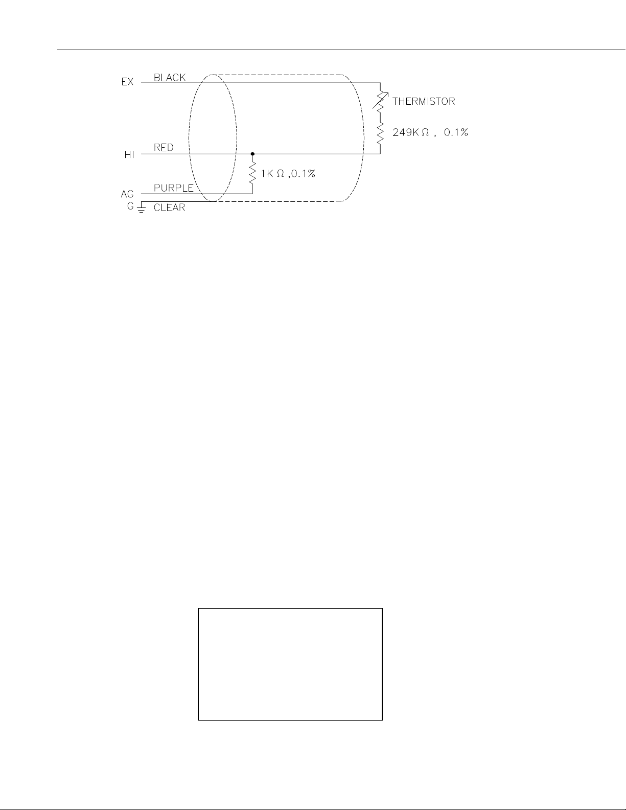
6.1 Therm107 Instruction
Therm107 instruction applies a precise 2500 mV excitation voltage and
measures the voltage drop across the 1K ohm resistor (Figure 6-1). The ratio
of measured voltage (Vs) to the excitation voltage (Vx) is related to thermistor
resistance (Rs), and the 1000 and 249K ohm fixed resistors as shown below:
Vs/Vx = 1000/(Rs+249000+1000)
Therm107 calculates Rs from the voltage ratio, and converts Rs to temperature
using the Steinhart-Hart equation:
T = 1/(A+B(LnRs)+C(LnRs)
Where T is the temperature returned in degrees Celsius, and A, B, and C are
coefficients provided by the thermistor manufacturer:
A = 8.271111E-4
B = 2.088020E-4
C = 8.059200E-8
3
) – 273.15
9
Page 14
Model 107 Temperature Probe
FIGURE 6-1. 107 Thermistor Probe Schematic
6.2 Temp(107) Instruction (P11)
The Temp(107) instruction (P11) applies a precise 2VAC (4VAC with the 21X
and CR7) excitation voltage and measures the voltage drop across the 1K ohm
resistor (Figure 6-2). The ratio of measured voltage (Vs) to the excitation
voltage (Vx) is related to thermistor resistance (Rs), and the 1000 and 249K
ohm fixed resistors as shown below:
Vs/Vx = 1000/(Rs+249000+1000)
th
Instruction P11 converts the ratio Vs/Vx * 800 to temperature using a 5
polynomial. The polynomial coefficients are shown in Table 6-1. Thermistor
resistance, and computed temperature over a -40 to +60 degree Celsius range is
shown in Table 6-2.
Parameter 3 specifies the excitation channel to be used for the measurement,
with options to increment the excitation channel for each repetition, integration
options for 60 or 50Hz noise rejection, and 10 ms delay for use with long lead
lengths (Sections 5.4 and 5.5):
Excitation/Integration Codes
Code Result
0x excite all rep with channel x
1x increment chan x with each rep
2x excite all reps with channel x, 60 Hz rejection, 10 ms delay
3x excite all reps with channel x, 50 Hz rejection, 10 ms delay
4x increment chan x with each rep, 60 Hz rejection, 10 ms delay
5x increment chan x with each rep, 50 Hz rejection, 10 ms delay
TABLE 6-1. Polynomial Coefficients
Coefficient Value
C0 -53.4601
C1 90.807
C2 -83.257
C3 52.283
C4 -16.723
C5 2.211
order
10
Page 15

Model 107 Temperature Probe
TABLE 6-2. Temperature, Resistance,
and Datalogger Output
Temperature °C Resistance OHMS Output °C
-40.00 4067212 -39.18
-38.00 3543286 -37.55
-36.00 3092416 -35.83
-34.00 2703671 -34.02
-32.00 2367900 -32.13
-30.00 2077394 -30.18
-28.00 1825568 -28.19
-26.00 1606911 -26.15
-24.00 1416745 -24.11
-22.00 1251079 -22.05
-20.00 1106485 -20.00
-18.00 980100 -17.97
-16.00 869458 -15.95
-14.00 772463 -13.96
-12.00 687276 -11.97
-10.00 612366 -10.00
-8.00 546376 -8.02
-6.00 488178 -6.05
-4.00 436773 -4.06
-2.00 391294 -2.07
0.00 351017 -0.06
2.00 315288 1.96
4.00 283558 3.99
6.00 255337 6.02
8.00 230210 8.04
10.00 207807 10.06
12.00 187803 12.07
14.00 169924 14.06
16.00 153923 16.05
18.00 139588 18.02
20.00 126729 19.99
22.00 115179 21.97
24.00 104796 23.95
26.00 95449 25.94
28.00 87026 27.93
30.00 79428 29.95
32.00 72567 31.97
34.00 66365 33.99
36.00 60752 36.02
38.00 55668 38.05
40.00 51058 40.07
42.00 46873 42.07
44.00 43071 44.05
46.00 39613 46.00
48.00 36465 47.91
50.00 33598 49.77
52.00 30983 51.59
54.00 28595 53.35
56.00 26413 55.05
58.00 24419 56.70
60.00 22593 58.28
11
Page 16

Model 107 Temperature Probe
7. Maintenance and Calibration
The 107 Probe requires minimal maintenance. For air temperature
measurements, check monthly to make sure the radiation shield is clean and
free from debris. Periodically check cabling for signs of damage and possible
moisture intrusion.
For most applications it is unnecessary to calibrate the 107 to eliminate the
thermistor offset. However, for those users that are interested, the following
briefly describes calibrating the 107 probes.
A single point calibration can be performed to determine the 107 temperature
offset (thermistor interchangeability). For Edlog dataloggers, the value of the
offset must be chosen so that the probe outputs the temperature calculated by the
polynomial, not the actual calibration temperature. For example, a 107 is placed
in a calibration chamber that is at 0°C and the probe outputs 0.1°C. An offset of
-0.16 is required for Edlog dataloggers, because at 0°C the polynomial calculates
a temperature of -0.06°C (Table 6-2).
NOTE
For all factory repairs and recalibrations, customers must get a
returned material authorization (RMA). Customers must also fill
out a “Declaration of Hazardous Material and Decontamination”
form and comply with the requirement specified in it. Refer to
the “Warranty and Assistance’ page for more information.
8. Troubleshooting
Symptom: Temperature is NAN, -INF, -9999
Verify the red wire is connected to the correct Single-Ended analog input
channel as specified by the measurement instruction, and the purple wire is
connected to datalogger ground.
Symptom: Temperature is -86, -53
Verify the black wire is connected to the switched excitation channel as
specified by the measurement instruction.
Symptom: Incorrect Temperature
Verify the multiplier and offset parameters are correct for the desired units
(Section 5). Check the cable for signs of damage and possible moisture
intrusion.
12
Symptom: Unstable Temperature
Try using the 60 or 50 Hz integration op tions, and/or increasing the settling
time as described in Sections 5.4 and 5.5. Make sure the clear shield wire is
connected to datalogger ground, and the datalogger is properly grounded.
Page 17

Page 18

Campbell Scientific Companies
Campbell Scientific, Inc. (CSI)
815 West 1800 North
Logan, Utah 84321
UNITED STATES
www.campbellsci.com • info@campbellsci.com
Campbell Scientific Africa Pty. Ltd. (CSAf)
PO Box 2450
Somerset West 7129
SOUTH AFRICA
www.csafrica.co.za • cleroux@csafrica.co.za
Campbell Scientific Australia Pty. Ltd. (CSA)
PO Box 444
Thuringowa Central
QLD 4812 AUSTRALIA
www.campbellsci.com.au • info@campbellsci.com.au
Campbell Scientific do Brazil Ltda. (CSB)
Rua Luisa Crapsi Orsi, 15 Butantã
CEP: 005543-000 São Paulo SP BRAZIL
www.campbellsci.com.br • suporte@campbellsci.com.br
Campbell Scientific Canada Corp. (CSC)
11564 - 149th Street NW
Edmonton, Alberta T5M 1W7
CANADA
www.campbellsci.ca • dataloggers@campbellsci.ca
Campbell Scientific Centro Caribe S.A. (CSCC)
300 N Cementerio, Edificio Breller
Santo Domingo, Heredia 40305
COSTA RICA
www.campbellsci.cc • info@campbellsci.cc
Campbell Scientific Ltd. (CSL)
Campbell Park
80 Hathern Road
Shepshed, Loughborough LE12 9GX
UNITED KINGDOM
www.campbellsci.co.uk • sales@campbellsci.co.uk
Campbell Scientific Ltd. (France)
Miniparc du Verger - Bat. H
1, rue de Terre Neuve - Les Ulis
91967 COURTABOEUF CEDEX
FRANCE
www.campbellsci.fr • info@campbellsci.fr
Campbell Scientific Spain, S. L.
Avda. Pompeu Fabra 7-9, local 1
08024 Barcelona
SPAIN
www.campbellsci.es • info@campbellsci.es
Please visit www.campbellsci.com to obtain contact information for your local US or International representative.
 Loading...