

Page 1

05103, 05103-45, 05106, and
05305 R.M. Young
Wind Monitors
Revision: 10/10
Copyright © 1984-2010
Campbell Scientific, Inc.
Page 2

Warranty and Assistance
The 05103, 05103-45, 05106, and 05305 R.M. YOUNG WIND
MONITORS are warranted by Campbell Scientific, Inc. to be free from
defects in materials and workmanship under normal use and service for twelve
(12) months from date of shipment unless specified otherwise. Batteries have
no warranty. Campbell Scientific, Inc.'s obligation under this warranty is
limited to repairing or replacing (at Campbell Scientific, Inc.'s option)
defective products. The customer shall assume all costs of removing,
reinstalling, and shipping defective products to Campbell Scientific, Inc.
Campbell Scientific, Inc. will return such products by surface carrier prepaid.
This warranty shall not apply to any Campbell Scientific, Inc. products which
have been subjected to modification, misuse, neglect, accidents of nature, or
shipping damage. This warranty is in lieu of all other warranties, expressed or
implied, including warranties of merchantability or fitness for a particular
purpose. Campbell Scientific, Inc. is not liable for special, indirect, incidental,
or consequential damages.
Products may not be returned without prior authorization. The following
contact information is for US and International customers residing in countries
served by Campbell Scientific, Inc. directly. Affiliate companies handle
repairs for customers within their territories. Please visit
www.campbellsci.com to determine which Campbell Scientific company
serves your country.
To obtain a Returned Materials Authorization (RMA), contact Campbell
Scientific, Inc., phone (435) 753-2342. After an applications engineer
determines the nature of the problem, an RMA number will be issued. Please
write this number clearly on the outside of the shipping container. Campbell
Scientific's shipping address is:
CAMPBELL SCIENTIFIC, INC.
RMA#_____
815 West 1800 North
Logan, Utah 84321-1784
For all returns, the customer must fill out a “Declaration of Hazardous Material
and Decontamination” form and comply with the requirements specified in it.
The form is available from our website at
completed form must be either emailed to repair@campbellsci.com
435-750-9579. Campbell Scientific will not process any returns until we
receive this form. If the form is not received within three days of product
receipt or is incomplete, the product will be returned to the customer at the
customer’s expense. Campbell Scientific reserves the right to refuse service on
products that were exposed to contaminants that may cause health or safety
concerns for our employees.
www.campbellsci.com/repair
. A
or faxed to
Page 3

05103, 05103-45, 05106, 05305
Table of Contents
PDF viewers note: These page numbers refer to the printed version of this document. Use
the Adobe Acrobat® bookmarks tab for links to specific sections.
1. General Description.....................................................1
2. Specifications ..............................................................1
3. Installation....................................................................3
3.1 Siting.........................................................................................................3
3.2 Assembly and Mounting...........................................................................3
4. Wiring............................................................................5
5. Example Programs......................................................6
5.1 Wind Speed ..............................................................................................6
5.2 Wind Direction.........................................................................................6
5.3 Wind Vector Processing Instruction.........................................................7
5.4 Example Programs....................................................................................7
5.4.1 CR1000 Example Program.............................................................8
5.4.2 CR10X Example Program ..............................................................8
5.5 Long Lead Lengths...................................................................................9
6. Sensor Maintenance..................................................10
7. Troubleshooting ........................................................10
7.1 Wind Direction.......................................................................................10
7.2 Wind Speed ............................................................................................11
8. References .................................................................11
Appendices
A. Wind Direction Sensor Orientation........................A-1
A.1 Determining Truth North and Sensor Orientation.............................. A-1
i
Page 4

05103, 05103-45, 05106, 05305 Table of Contents
B. Wind Direction Measurement Theory....................B-1
B.1 BRHalf Instruction.............................................................................. B-1
B.2 EX-DEL-SE (P4) Instruction .............................................................. B-2
Figures
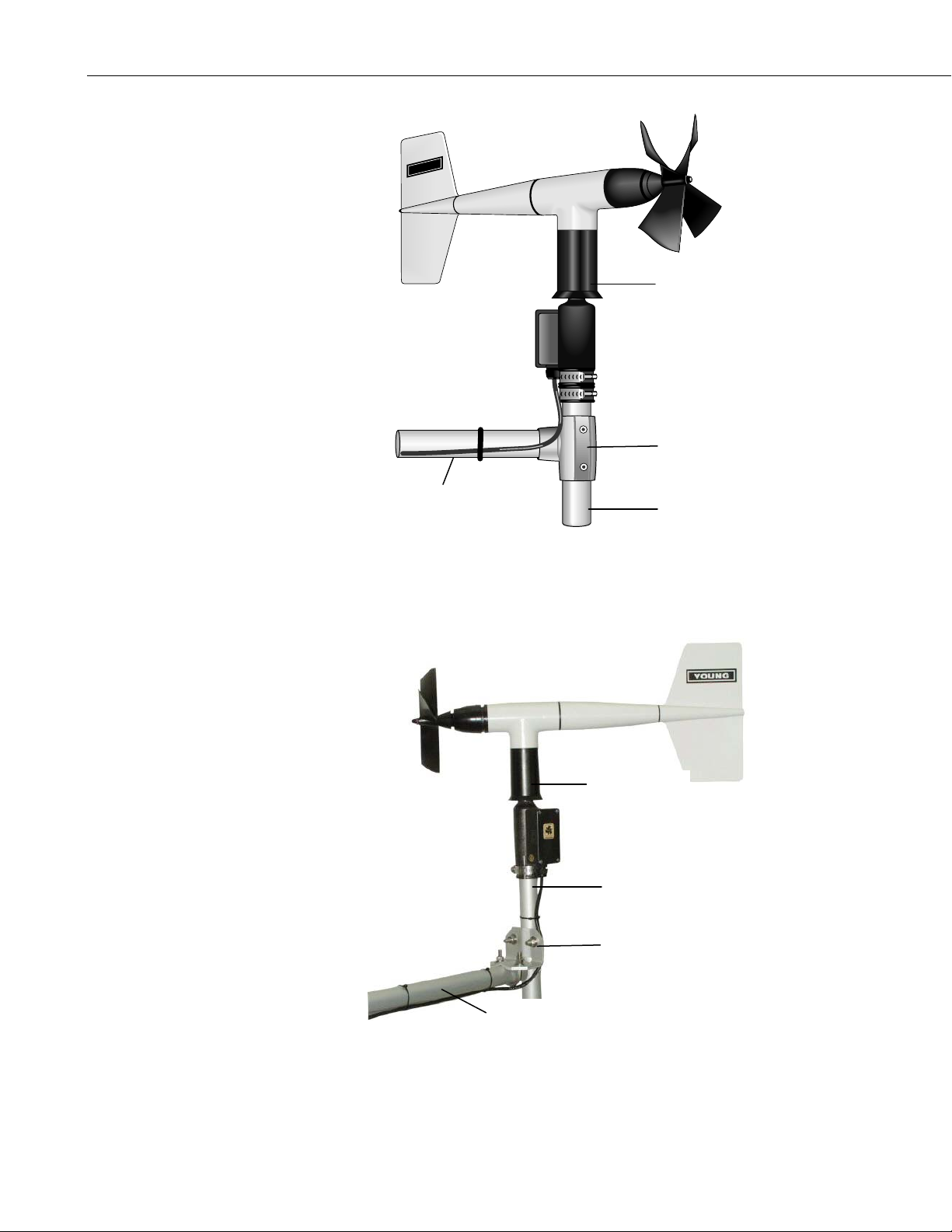
3-1. Wind Monitor Mounted to a CM200 Series Crossarm
with PN 17953 Nu-Rail....................................................................... 4
3-2. Wind Monitor Mounted to a CM200 Series Crossarm
with CM220 Right Angle Mounting Kit............................................. 4
3-3. CM220 Right Angle Mounting Kit Mounted to a Crossarm.................. 5
A-1. Magnetic Declination for the Contiguous United States ................... A-2
A-2. Declination Angles East of True North are Subtracted From 0 to
Get True North................................................................................ A-2
A-3. Declination Angles West of True North are Added to 0 to
Get True North................................................................................ A-3
B-1. 05103 Potentiometer in a Half Bridge Circuit ................................... B-1
Tables
1-1. Recommended Lead Lengths .................................................................1
4-1. Connections to Campbell Scientific Dataloggers................................... 5
5-1. Wind Speed Multiplier (with Configuration Code 21)........................... 6
5-2. Parameters for Wind Direction............................................................... 7
5-3. Wiring for Example Programs................................................................ 7
ii
Page 5

05103, 05103-45, 05106, and 05305 R.M. Young Wind Monitors
1. General Description
The 05103, 05103-45, 05106, and 05305 Wind Monitor sensors are used to
measure horizontal wind speed and direction. The 05305 is a high
performance version of the 05103 designed to meet PSD specifications for air
quality applications. The 05103-45 is an alpine version that discourages ice
buildup. The 05106 is recommended for marine applications.
Wind speed is measured with a helicoid-shaped, four-blade propeller. Rotation
of the propeller produces an AC sine wave signal with frequency proportional
to wind speed.
Vane position is transmitted by a 10K ohm potentiometer. With a precision
excitation voltage applied, the output voltage is proportional to wind direction.
The R.M. Young Instruction Manual includes additional information on the
operating principles, installation and maintenance of the sensor.
Lead length for the Wind Monitor is specified when the sensor is ordered.
Table 1-1 gives the recommended lead length for mounting the sensor at the
top of the tripod/tower with a CM200-series crossarm.
CM6 CM10 CM110 CM115 CM120 UT10 UT20 UT30
10’ 13’ 13’ 19’ 24’ 13’ 24’ 34’
The Wind Monitors ship with:
(1) Allen wrench from mfg
(1) Bearing spacer from mfg
(1) Calibration Sheet
(1) Instruction Manual
(1) 3659 Mounting pipe
2. Specifications
05103, 05103-45, and
Wind Speed
Range: 0-224 mph (0-100 m s
Accuracy: ±0.6 mph (±0.3 m s
Starting threshold: 2.2 mph (1.0 m s
Distance constant
(63% recovery): 8.9 ft (2.7 m)
TABLE 1-1. Recommended Lead Lengths
05305
05106
-1
) 0-112 mph (0-50 m s-1)
-1
of reading
2.4 mph (1.1 m s
) or 1%
-1
) 05103;
-1
) 05106
±0.4 mph (±0.2 m s-1) or
1% of reading
0.9 mph (0.4 m s
6.9 ft (2.1 m)
-1
)
1
Page 6

05103, 05103-45, 05106, and 05305 R.M. Young Wind Monitors
05103, 05103-45, and
05106
Resolution: (0.2192 mph)/
(scan rate in seconds) or
(0.0980 m s
(scan rate in seconds)
Output: ac voltage (3 pulses per
revolution). 1800 rpm
(90 Hz) = 19.7 mph
(8.8 m s
-1
Wind Direction
Range: 0-360° mechanical,
355° electrical (5° open)
Accuracy: ±3° (05103, 05106)
±5° (05103-45)
Starting threshold
at 10° displacement: 2.4 mph (1.1 m s
Delay distance
(50% recovery): 4.3 ft (1.3 m)
Damping ratio: 0.3 0.45
Damped natural
wavelength:
Undamped natural
wavelength:
24.3 ft (7.4 m)
23.6 ft (7.2 m)
Output: Analog dc voltage from
potentiometer – resistance
10 kΩ, linearity 0.25%,
life expectancy 50 million
revolutions.
Power
Switched excitation
voltage supplied
by the datalogger.
Physical
Operating
Temperature
-50° to +50°C, assuming
non-riming conditions
Dimensions
Overall: 14.6” H x 21.7” L
(37 cm x 55 cm)
Main housing
Diameter:
2.0“ (5 cm)
Propeller Diameter: 7.1” (18 cm) (05103, 05106)
5.5” (14 cm) (05103-45)
Mounting Pipe: 1.34” (34 mm) OD;
standard 1.0” IPS
schedule 40
Weight
3.2 lbs (1.5 kg) (05103, 05106)
2.2 lbs (1 kg) (05103-45)
05305
(0.2290 mph)/
-1
)/
(scan rate in seconds) or
(0.1024 m s
-1
)/
(scan rate in seconds)
ac voltage (3 pulses per
revolution) 1800 rpm
(90 Hz) = 20.6 mph
)
(9.2 m s
-1
)
Same
±3°
-1
)
1.0 mph (0.5 m s-1)
3.9 ft (1.2 m)
16.1 ft (4.9 m)
14.4 ft (4.4 m)
Same
Same
-50° to +50°C, assuming
non-riming conditions
15.0” H x 25.6“ L
(38 cm x 65 cm)
Same
7.9” (20 cm)
Same
2.5 lbs (1.1 kg)
2
Manufactured by RM Young (Traverse City, MI) and cabled by Campbell
Scientific for use with our dataloggers.
Page 7

05103, 05103-45, 05106, and 05305 R.M. Young Wind Monitors
NOTE
3. Installation
3.1 Siting
3.2 Assembly and Mounting
The black outer jacket of the cable is Santoprene® rubber. This
compound was chosen for its resistance to temperature extremes,
moisture, and UV degradation. However, this jacket will
support combustion in air. It is rated as slow burning when
tested according to U.L. 94 H.B. and will pass FMVSS302.
Local fire codes may preclude its use inside buildings.
Locate wind sensors away from obstructions (e.g. trees and building).
Generally, there should be a horizontal distance of at least ten times the height
of the obstruction between the windset and the obstruction. If the sensors need
to be mounted on a roof, the height of the sensors above the roof, should be at
least 1.5 times the height of the building. See Section 9 for a list of references
that discuss siting wind speed and direction sensors.
Tools Required:
• 5/64” Allen wrench
• 1/2” open end wrench
• compass and declination angle for the site (see Appendix A)
• small screw driver provided with datalogger
• UV resistant cable ties
• small pair of diagonal-cutting pliers
• 6 - 10” torpedo level
Install the propeller to its shaft using the nut provided with the sensor.
The Wind Monitor mounts to a standard 1” IPS schedule 40 pipe (1.31” O.D.).
A 12” long mounting pipe ships with the Wind Monitor for attaching the
sensor to a CM200-series crossarm with the CM220 or 1049 NU-RAIL fitting
(Figures 3-1 and 3-2). The 05103 can also be mounted to a CM110 series
tripod mast with the CM216 Mast Mounting Kit (see Figure 3-3).
Mount the CM200-series crossarm to the tripod or tower. Orient the crossarm
North-South, with the 1” NU-RAIL or CM220 on the North end. Appendix A
contains detailed information on determining true north using a compass and
the magnetic declination for the site.
Secure the mounting pipe to the NU-RAIL or CM220. Place the orientation
ring, followed by the Wind Monitor on the mounting pipe. Orient the junction
box to the south, and tighten the band clamps on the orientation ring and
mounting post. Final sensor orientation is done after the datalogger has been
programmed to measure wind direction as described in Appendix A.
Route the sensor cable along the underside of the crossarm to the tower/tripod
mast, and to the instrument enclosure. Secure the sensor cable to the crossarm
and mast using cable ties.
3
Page 8
05103, 05103-45, 05106, and 05305 R.M. Young Wind Monitors
YOUNG
Wind Monitor
PN 17953 Nu-Rail
CM200 Series Crossarm
Mounting Pipe
(supplied with sensor)
FIGURE 3-1. Wind Monitor Mounted to a CM200 Series Crossarm
with PN 17953 Nu-Rail
Wind Monitor
Mounting Pipe
(supplied with sensor)
CM220
4
CM200 Series Crossarm
FIGURE 3-2. Wind Monitor Mounted to a CM200 Series Crossarm
with CM220 Right Angle Mounting Kit
Page 9

05103, 05103-45, 05106, and 05305 R.M. Young Wind Monitors
CM220
CM200-Series Crossarm
4. Wiring
FIGURE 3-3. CM220 Right Angle Mounting Kit Mounted to a Crossarm
Connections to Campbell Scientific dataloggers are given in Table 4-1. When
Short Cut for Windows software is used to create the datalogger program, the
sensor should be wired to the channels shown in the wiring diagram created by
Short Cut.
TABLE 4-1. Connections to Campbell Scientific Dataloggers
Color
Red Wind Spd.
Description
CR800
CR5000
CR3000
CR1000
CR510
CR500
CR10(X)
21X,
CR7
CR23X
CR200(X)
Pulse Pulse Pulse P_LL
Signal
Black Wind Spd.
G
Reference
Green Wind Dir. Signal SE Analog SE
Analog
SE
Analog
SE Analog
Blue Wind Dir.
Excitation
White Wind Dir.
Reference
Clear Shield wire
Excitation Excitation Excitation Excitation
AG
G
5
Page 10

05103, 05103-45, 05106, and 05305 R.M. Young Wind Monitors
5. Example Programs
This section is for users who write their own programs. A datalogger program
to measure this sensor can be created using Campbell Scientific’s Short Cut
Program Builder software. You do not need to read this section to use Short
Cut.
5.1 Wind Speed
Wind speed is measured with the Pulse Count instruction, and with the low
level AC configuration. For dataloggers programmed with Edlog, specify
configuration code 21 to output frequency in Hertz.
The expression for wind speed (U) is:
U = MX + B
where
M = multiplier
X = number of pulses per second (Hertz)
B = offset
Table 5-1 lists the multipliers to obtain miles/hour or meters/second when the
Pulse Count instruction is configured to output Hz (configuration code 21).
The helicoid propeller has a calibration that passes through zero, so the offset
is zero (Gill, 1973; Baynton, 1976).
05103, 05103-45, or 05106 0.2192 0.0980
*When configuration code 11 is used, the multiplier above is divided by the
execution interval in seconds.
5.2 Wind Direction
The wind vane is coupled to a 10K potentiometer, which has a 5 degree
electrical dead band between 355 and 360 degrees. A 1 M ohm resistor
between the signal and ground pulls the signal to 0 mV (0 degrees) when wind
direction is between 355 and 360 degrees.
The EX-DEL_SE measurement instruction is used for dataloggers that are
programmed with Edlog (e.g. CR10X, CR23X) and the CR200(X). The
measurement result is mV; the multiplier to convert mV to degrees is
355deg/excitation mV.
TABLE 5-1. Wind Speed Multiplier
(With Configuration Code 21*)
Model
05305 0.2290 0.1024
Miles/
Hour Output
Meters/
Second Output
6
The BRHalf measurement instruction is used for dataloggers that are
programmed with CRBasic (e.g. CR1000, CR3000). The multiplier to convert
the measurement result (mV/excitation mV) to degrees is 355.
Page 11

05103, 05103-45, 05106, and 05305 R.M. Young Wind Monitors
Some CR1000 measurement sequences cause the measurement of the wind
direction to return a negative wind direction (-30º) while in the dead band.
This can be overcome by using a delay of 40 ms (40,000µs) or by setting
negative wind direction values to 0.0: If WindDir < 0, then WindDir = 0.0.
The excitation voltage, range codes, and multipliers for the different datalogger
types are listed in Table 5-2. Appendix B has additional information on the P4
and BRHalf measurement instructions.
TABLE 5-2. Parameters for Wind Direction
CR10(X),
CR510,
CR200(X)
Measurement
Range
Excitation
2500 mV,
slow
2500 mV 5000 mV 2500 mV 5000 mV
CR7, 21X,
CR23X
5000 mV,
slow/60 Hz
Voltage
Multiplier 0.142 0.071 355 355
Offset 0 0 0 0
5.3 Wind Vector Processing Instruction
The Wind Vector output instruction is used to process and store mean wind
speed, unit vector mean wind direction, and Standard Deviation of the wind
direction (optional) using the measured wind speed and direction samples.
5.4 Example Programs
The following programs measure the Wind Monitor 05103 every 5 seconds,
and store mean wind speed, unit vector mean direction, and standard deviation
of the direction every 60 minutes. Wiring for the examples is given in Table
5-3.
CR800
CR1000
2500 mV,
60 Hz, reverse
excitation
CR5000,
CR3000
5000 mV,
60 Hz, reverse
excitation
TABLE 5-3. Wiring for Example Programs
Color Description CR1000 CR10X
Red Wind Spd. Signal P1 P1
Black Wind Spd. Reference
G
Green Wind Dir. Signal SE 1 SE 1
Blue Wind Dir. Excitation EX 1 E1
White Wind Dir. Reference
Clear Shield wire
AG
G
7
Page 12

05103, 05103-45, 05106, and 05305 R.M. Young Wind Monitors
5.4.1 CR1000 Example Program
'CR1000
'Declare Variables and Units
Public Batt_Volt
Public WS_ms
Public WindDir
Units Batt_Volt=Volts
Units WS_ms=meters/second
Units WindDir=Degrees
'Define Data Tables
DataTable(Table1,True,-1)
DataInterval(0,60,Min,10)
WindVector (1,WS_ms,WindDir,FP2,False,0,0,0)
FieldNames("WS_ms_S_WVT,WindDir_D1_WVT,WindDir_SD1_WVT")
EndTable
'Main Program
BeginProg
Scan(5,Sec,1,0)
'Default Datalogger Battery Voltage measurement Batt_Volt:
Battery(Batt_Volt)
'05103 Wind Speed & Direction Sensor measurements WS_ms and WindDir:
PulseCount(WS_ms,1,1,1,1,0.098,0)
BrHalf(WindDir,1,mV2500,1,1,1,2500,True,0,_60Hz,355,0) ‘ mV5000
‘range, 5000 mV excitation for CR3000 and CR5000 dataloggers
If WindDir>=360 Then WindDir=0
If WindDir<0 Then WindDir=0
'Call Data Tables and Store Data
CallTable(Table1)
NextScan
EndProg
8
5.4.2 CR10X Example Program
;{CR10X}
*Table 1 Program
01: 5.0000 Execution Interval (seconds)
1: Pulse (P3)
1: 1 Reps
2: 1 Pulse Channel 1
3: 21 Low Level AC, Output Hz
4: 3 Loc [ WS_ms ]
5: 0.098 Multiplier
6: 0 Offset
Page 13

05103, 05103-45, 05106, and 05305 R.M. Young Wind Monitors
2: Excite-Delay (SE) (P4)
1: 1 Reps
2: 5 2500 mV Slow Range ; 5000 mV(slow/60 hz) Range for CR23X, 21X, CR7
3: 1 SE Channel
4: 1 Excite all reps w/Exchan 1
5: 2 Delay (0.01 sec units)
6: 2500 mV Excitation ; 5000 mV for CR23X, 21X, CR7
7: 4 Loc [ WindDir ]
8: 0.142 Multiplier ; 0.071 for CR23X, 21X, CR7
9: 0 Offset
3: If (X<=>F) (P89)
1: 4 X Loc [ WindDir ]
2: 3 >=
3: 360 F
4: 30 Then Do
4: Z=F x 10^n (P30)
1: 0 F
2: 0 n, Exponent of 10
3: 4 Z Loc [ WindDir ]
5: End (P95)
6: If time is (P92)
1: 0 Minutes (Seconds --) into a
2: 60 Interval (same units as above)
3: 10 Set Output Flag High (Flag 0)
7: Set Active Storage Area (P80)
1: 1 Final Storage Area 1
2: 101 Array ID
8: Real Time (P77)
1: 1220 Year,Day,Hour/Minute (midnight = 2400)
9: Wind Vector (P69)
1: 1 Reps
2: 0 Samples per Sub-Interval
3: 0 S, theta(1), sigma(theta(1)) with polar sensor
4: 3 Wind Speed/East Loc [ WS_ms ]
5: 4 Wind Direction/North Loc [ WindDir ]
5.5 Long Lead Lengths
When sensor lead length exceeds 100 feet, the settling time allowed for the
measurement of the vane should be increased to 20 milliseconds.
For dataloggers programmed with Edlog (and the CR200(X)), the EX-DEL-SE
(P4) measurement instruction should be used. Enter a 2 in the P4 “Delay”
parameter for a 20 millisecond delay.
9
Page 14

05103, 05103-45, 05106, and 05305 R.M. Young Wind Monitors
For dataloggers programmed with CRBasic, increase the “Settling Time”
parameter of the BRHalf instruction to 20 milliseconds (20,000 microseconds).
CAUTION
The 60 Hz rejection option can not be used with the DC
Half Bridge instruction, when the delay is not zero. Do not
use long lead lengths in electrically noisy environments.
6. Sensor Maintenance
Every month do a visual/audio inspection of the anemometer at low wind
speeds. Verify that the propeller and wind vane bearing rotate freely. Inspect
the sensor for physical damage.
Replace the anemometer bearings when they become noisy, or the wind speed
threshold increases above an acceptable level. The condition of the bearings
can be checked with a paper clip as described in the R.M. Young manual.
The potentiometer has a life expectancy of fifty million revolutions. As it
becomes worn, the element can produce noisy signals or become non-linear.
Replace the potentiometer when the noise or non-linearity becomes
unacceptable.
Contact Campbell Scientific for a Return Materials Authorization (RMA)
number at (435) 753-2342.
7. Troubleshooting
7.1 Wind Direction
Symptom: -9999 or no change in direction
1. Check that the sensor is wired to the Excitation and Single-Ended channel
2. Verify that the excitation voltage and Range code are correct for the
3. Disconnect the sensor from the datalogger and use an ohm meter to check
Symptom: Incorrect wind direction
1. Verify that the Excitation voltage, Range code, multiplier and offset
2. Check orientation of sensor as described in Section 3.
specified by the measurement instruction.
datalogger type.
the potentiometer. Resistance should be about 10K ohms between the
Blue and White wires. The resistance between either the Blue/Green or
White/Green wires should vary between about 1K to 11K depending on
vane position. Resistance when the vane is in the 5 degree dead band
should be about 1M ohm.
parameters are correct for the datalogger type.
10
Page 15

7.2 Wind Speed
05103, 05103-45, 05106, and 05305 R.M. Young Wind Monitors
Symptom: No wind speed
1. Check that the sensor is wired to the Pulse channel specified by the Pulse
count instruction.
2. Disconnect the sensor from the datalogger and use an ohm meter to check
the coil. The resistance between the red and black wires should be about
2075 ohms. Infinite resistance indicates an open coil; low resistance
indicates a shorted coil.
3. Verify that the Configuration Code, and Multiplier and Offset parameters
for the Pulse Count instruction are correct for the datalogger type.
Symptom: Wind speed does not change
1. For the dataloggers that are programmed with Edlog, the input location
for wind speed is not updated if the datalogger is getting “Program Table
Overruns”. Increase the execution interval (scan rate) to prevent
overruns.
8. References
Gill, G.C., 1973: The Helicoid Anemometer Atmosphere, II, 145-155.
Baynton, H.W., 1976: Errors in Wind Run Estimates from Rotational
Anemometers Bul. Am. Met. Soc., vol. 57, No. 9, 1127-1130.
The following references give detailed information on siting wind speed and
wind direction sensors.
EPA, 1989: Quality Assurance Handbook for Air Pollution Measurements
System, Office of Research and Development, Research Triangle Park, NC,
27711.
EPA, 1987: On-Site Meteorological Program Guidance for Regulatory
Modeling Applications, EPA-450/4-87-013, Office of Air Quality Planning
and Standards, Research Triangle Park, NC 27711.
The State Climatologist, 1985: Publication of the American Association of
State Climatologists: Height and Exposure Standards, for Sensors on
Automated Weather Stations, vol. 9, No. 4.
WMO, 1983: Guide to Meteorological Instruments and Methods of
Observation, World Meteorological Organization, No. 8, 5th edition, Geneva,
Switzerland.
11
Page 16

05103, 05103-45, 05106, and 05305 R.M. Young Wind Monitors
12
Page 17

Appendix A. Wind Direction Sensor Orientation
A.1 Determining True North and Sensor Orientation
Orientation of the wind direction sensor is done after the datalogger has been
programmed, and the location of True North has been determined. True North is
usually found by reading a magnetic compass and applying the correction for
magnetic declination; where magnetic declination is the number of degrees
between True North and Magnetic North. Magnetic declination for a specific site
can be obtained from a USGS map, local airport, or through a computer service
offered by the USGS at www.ngdc.noaa.gov/geomag. A general map showing
magnetic declination for the contiguous United States is shown in Figure A-1.
Declination angles east of True North are considered negative, and are subtracted
from 0 degrees to get True North as shown Figure A-2. Declination angles west
of True North are considered positive, and are added to 0 degrees to g et Tru e
North as shown in Figure A-3. For example, the declination for Logan, Utah is
14° East. True North is 360° - 14°, or 346° as read on a compass.
Orientation is most easily done with two people, one to aim and adjust the
sensor, while the other observes the wind direction displayed by the
datalogger.
1. Establish a reference point on the horizon for True North.
2. Sighting down the instrument center line, aim the nose cone, or
counterweight at True North. Display the input location or variable for wind
direction using a hand-held keyboard display, PC, or palm.
3. Loosen the u-bolt on the CM220 or the set screws on the Nu-Rail that secure
the base of the sensor to the crossarm. While holding the vane position,
slowly rotate the sensor base until the datalogger indicates 0 degrees.
Tighten the set screws.
A-1
Page 18

Appendix A. Wind Direction Sensor Orientation
Subtract declination from 360° Add declination to 0°
20 W
18 W
16 W
14 W
12 W
10 W
8 W
6 W
4 W
20 E
18 E
22 E
16 E
14 E
12 E
10 E
8 E
6 E
4 E
2 E
2 W
0
FIGURE A-1. Magnetic Declination for the Contiguous United States
A-2
FIGURE A-2. Declination Angles East of True North Are Subtracted
From 0 to Get True North
Page 19

Appendix A. Wind Direction Sensor Orientation
FIGURE A-3. Declination Angles West of True North Are Added to 0 to
Get True North
A-3
Page 20

Appendix A. Wind Direction Sensor Orientation
This is a blank page.
A-4
Page 21

Appendix B. Wind Direction
(
+
=
Measurement Theory
It is not necessary to understand the concepts in this section for the general
operation of the 05103 with Campbell Scientific’s datalogger.
FIGURE B-1. 05103 Potentiometer in a Half Bridge Circuit
B.1 BRHalf Instruction
The BRHalf instruction outputs a precise excitation voltage (Vx), and measures
the voltage between the wiper and ground (V
wiper and ground, R
result is the ratio of the measured voltage to the excitation voltage (V
ratio is related to the resistance as shown below:
The maximum value that R
west side of north to the east side of north (at this point R
its maximum value of 1.0 mV/mV at 355 degrees. The multiplier to convert
to degrees is 355 degrees / 1.0 Vs/Vx = 355. Since the datalogger outputs
V
s/Vx
the ratio V
even though they use a different excitation voltage. See Section 13.5 in the
datalogger manual from more informati on on the bri d ge m easurements.
s / Vx
). The resistance between the
s
, and Vs varies with wind direction. The measurement
s
)
RRRVV
stsxs
will reach is Rf, just before it crosses over from the
s
, the multiplier is the same for both the CR10(X) and CR3000,
= 0). Vs / Vx reaches
t
s/Vx
). This
B-1
Page 22

Appendix B. Wind Direction Measurement Theory
(
+
B.2 EX-DEL-SE (P4) Instruction
Instruction 4 outputs a precise excitation voltage (Vx) and measures the voltage
between the wiper and analog ground, V
and analog ground, R
the measured voltage, V
shown below:
⋅=
, and Vs varies with wind direction. Instruction 4 outputs
s
. This measured voltage is related to resistance as
s
)
RRRVV
stsxs
. The resistance between the wiper
s
The maximum value that R
west side of north to the east side of north (at this point R
maximum value of V
will reach is Rf just before it crosses over from the
s
= 0). Vs reaches its
t
. This maximum voltage equals 2500 mV for an
x
excitation voltage of 2500 mV recommended for the CR10( X) and 5000 mV
for an excitation voltage of 5000 mV recommended for the CR23X at 355
degrees. The multiplier to convert V
to degrees is 355 degrees / 2500 mV =
s
0.142 for the CR10X, or, 355 degrees / 5000 mV = 0.071 for the CR23X. See
Section 13.5 in the datalogger manual from more information on the bridge
measurements
B-2
Page 23

Page 24

Campbell Scientific Companies
Campbell Scientific, Inc. (CSI)
815 West 1800 North
Logan, Utah 84321
UNITED STATES
www.campbellsci.com • info@campbellsci.com
Campbell Scientific Africa Pty. Ltd. (CSAf)
PO Box 2450
Somerset West 7129
SOUTH AFRICA
www.csafrica.co.za • cleroux@csafrica.co.za
Campbell Scientific Australia Pty. Ltd. (CSA)
PO Box 444
Thuringowa Central
QLD 4812 AUSTRALIA
www.campbellsci.com.au • info@campbellsci.com.au
Campbell Scientific do Brazil Ltda. (CSB)
Rua Luisa Crapsi Orsi, 15 Butantã
CEP: 005543-000 São Paulo SP BRAZIL
www.campbellsci.com.br • suporte@campbellsci.com.br
Campbell Scientific Canada Corp. (CSC)
11564 - 149th Street NW
Edmonton, Alberta T5M 1W7
CANADA
www.campbellsci.ca • dataloggers@campbellsci.ca
Campbell Scientific Centro Caribe S.A. (CSCC)
300 N Cementerio, Edificio Breller
Santo Domingo, Heredia 40305
COSTA RICA
www.campbellsci.cc • info@campbellsci.cc
Campbell Scientific Ltd. (CSL)
Campbell Park
80 Hathern Road
Shepshed, Loughborough LE12 9GX
UNITED KINGDOM
www.campbellsci.co.uk • sales@campbellsci.co.uk
Campbell Scientific Ltd. (France)
Miniparc du Verger - Bat. H
1, rue de Terre Neuve - Les Ulis
91967 COURTABOEUF CEDEX
FRANCE
www.campbellsci.fr • info@campbellsci.fr
Campbell Scientific Spain, S. L.
Avda. Pompeu Fabra 7-9, local 1
08024 Barcelona
SPAIN
www.campbellsci.es • info@campbellsci.es
Please visit www.campbellsci.com to obtain contact information for your local US or International representative.
 Loading...