

Page 1

Model 014A Met One
Wind Speed Sensor
Revision: 3/11
REGCOMENDED
Feed SENSORS
Serial
27115
Portland Or USA
Copyright © 1980-2011
Campbell Scientific, Inc.
Page 2

Warranty and Assistance
The 014A MET-ONE WIND SPEED SENSOR is warranted by Campbell
Scientific, Inc. to be free from defects in materials and workmanship under
normal use and service for twelve (12) months from date of shipment unless
specified otherwise. Batteries have no warranty. Campbell Scientific, Inc.'s
obligation under this warranty is limited to repairing or replacing (at Campbell
Scientific, Inc.'s option) defective products. The customer shall assume all
costs of removing, reinstalling, and shipping defective products to Campbell
Scientific, Inc. Campbell Scientific, Inc. will return such products by surface
carrier prepaid. This warranty shall not apply to any Campbell Scientific, Inc.
products which have been subjected to modification, misuse, neglect, accidents
of nature, or shipping damage. This warranty is in lieu of all other warranties,
expressed or implied, including warranties of merchantability or fitness for a
particular purpose. Campbell Scientific, Inc. is not liable for special, indirect,
incidental, or consequential damages.
Products may not be returned without prior authorization. The following
contact information is for US and International customers residing in countries
served by Campbell Scientific, Inc. directly. Affiliate companies handle
repairs for customers within their territories. Please visit
www.campbellsci.com to determine which Campbell Scientific company
serves your country.
To obtain a Returned Materials Authorization (RMA), contact Campbell
Scientific, Inc., phone (435) 753-2342. After an applications engineer
determines the nature of the problem, an RMA number will be issued. Please
write this number clearly on the outside of the shipping container. Campbell
Scientific's shipping address is:
CAMPBELL SCIENTIFIC, INC.
RMA#_____
815 West 1800 North
Logan, Utah 84321-1784
For all returns, the customer must fill out a “Declaration of Hazardous Material
and Decontamination” form and comply with the requirements specified in it.
The form is available from our website at
completed form must be either emailed to repair@campbellsci.com
435-750-9579. Campbell Scientific will not process any returns until we
receive this form. If the form is not received within three days of product
receipt or is incomplete, the product will be returned to the customer at the
customer’s expense. Campbell Scientific reserves the right to refuse service on
products that were exposed to contaminants that may cause health or safety
concerns for our employees.
www.campbellsci.com/repair
. A
or faxed to
Page 3

014A Table of Contents
PDF viewers note: These page numbers refer to the printed version of this document. Use
the Adobe Acrobat® bookmarks tab for links to specific sections.
1. General .........................................................................1
2. Specifications ..............................................................1
3. Installation....................................................................2
3.1 Siting.........................................................................................................2
3.2 Assembly and Mounting...........................................................................2
4. Wiring............................................................................ 3
5. Programming ...............................................................4
5.1 Wind Speed ..............................................................................................4
5.2 Example Programs....................................................................................5
5.2.1 Pulse Port Examples .......................................................................5
5.2.1.1 CR1000 Example Program....................................................5
5.2.1.2 CR10X Example Program.....................................................6
5.2.2 Control Port Example Program.......................................................7
6. Maintenance ................................................................. 7
6.1 Suggested Maintenance Schedules ...........................................................7
6.1.1 6-12 Month Periodic Service ..........................................................7
6.1.2 12-24 Month Service ......................................................................8
6.1.3 24-36 Month Service ......................................................................8
7. Troubleshooting ..........................................................8
8. References ...................................................................8
Appendices
A. Sensor Maintenance ............................................... A-1
A.1 Reed Switch Replacement Procedure ................................................. A-1
A.2 Bearing Replacement Procedure......................................................... A-1
B. Theory of Operation................................................ B-1
B.1 Mechanical...........................................................................................B-1
B.2 Calibration............................................................................................B-1
i
Page 4

014A Table of Contents
Figures
Table
3-1. 014A Mounted on a CM200 Series Crossarm with PN 1049................. 3
3-2. 014A Mounted on a CM200 Series Crossarm with CM220................... 3
A-1. Reed Switch Assembly ...................................................................... A-1
A-2. Cable Diagram ................................................................................... A-2
A-3. Parts Diagram ....................................................................................A-3
1-1. Recommended Lead Lengths ................................................................. 1
4-1. Connections to Campbell Scientific Dataloggers, Pulse Channels......... 4
4-2. Connections to Campbell Scientific Dataloggers, Control Ports............ 4
5-1. Wind Speed Multiplier ........................................................................... 5
5-2. Wiring for Pulse Port Example Programs .............................................. 5
A-1. Met-One Parts List............................................................................. A-4
ii
Page 5

Met-One 014A Wind Speed Sensor
1. General
The 014A is a three-cup anemometer that is used to measure horizontal wind
speed. Rotation of the cup wheel opens and closes a reed switch at a rate
proportional to wind speed.
The accompanying Met One manual contains additional information on
operating principals, installation, and maintenance.
Lead length for the 014A is specified when the sensor is ordered. Table 1-1
gives the recommended lead length for mounting the sensor at the top of the
tripod/tower with a 019ALU or CM200 series crossarm.
TABLE 1-1. Recommended Lead Lengths
CM6 CM10 CM110 CM115 CM120 UT10 UT20 UT30
11’ 14’ 14’ 19’ 24’ 14’ 24’ 37’
The 014A ships with:
(1) Calibration Sheet
(1) Instruction Manual
(1) 014ACBL-L Sensor Cable w/user specified length
2. Specifications
Threshold 0.45 m/s (1 mph)
Calibrated Range 0-45 m/s (0-100 mph)
Gust Survival 0-53 m/s (0-120 mph)
Accuracy 1.5% or .11 m/s (0.25 mph)
Temperature Range -50 C to +70 C
Distance Constant*
Standard: Less than 4.6m (15 ft.)
(Aluminum Cups)
Optional Fast Response: Less than 1.5 m (5 ft.)
(Lexan Cups)
Output Signal Contact Closure, Reed Switch
Weight 680 grams (1.5 lbs)
* The distance traveled by the air after a sharp-edged gust has occurred for the
anemometer to reach 63% of the new speed.
1
Page 6

Met-One 014A Wind Speed Sensor
NOTE
The black outer jacket of the cable is Santoprene
compound was chosen for its resistance to temperature extremes,
moisture, and UV degradation. However, this jacket will
support combustion in air. It is rated as slow burning when
tested according to U.L. 94 H.B. and will pass FMVSS302.
Local fire codes may preclude its use inside buildings.
3. Installation
3.1 Siting
Locate wind sensors away from obstructions (e.g. trees and building). As a
general rule of thumb there should be a horizontal distance of at least ten times
the height of the obstruction between the windset and the obstruction. If it is
necessary to mount the sensors on the roof of a building, the height of the
sensors, above the roof, should be at least 1.5 times the height of the building.
See Section 8 for a list of references that discuss siting wind speed and
direction sensors.
®
rubber. This
3.2 Assembly and Mounting
Tools Required:
• 1/2” open end wrench
• 5/64” Allen wrench
• compass and declination angle for the site
• small screw driver provided with datalogger
• UV resistant cable ties
• small pair of diagonal-cutting pliers
• 6 - 10” torpedo level
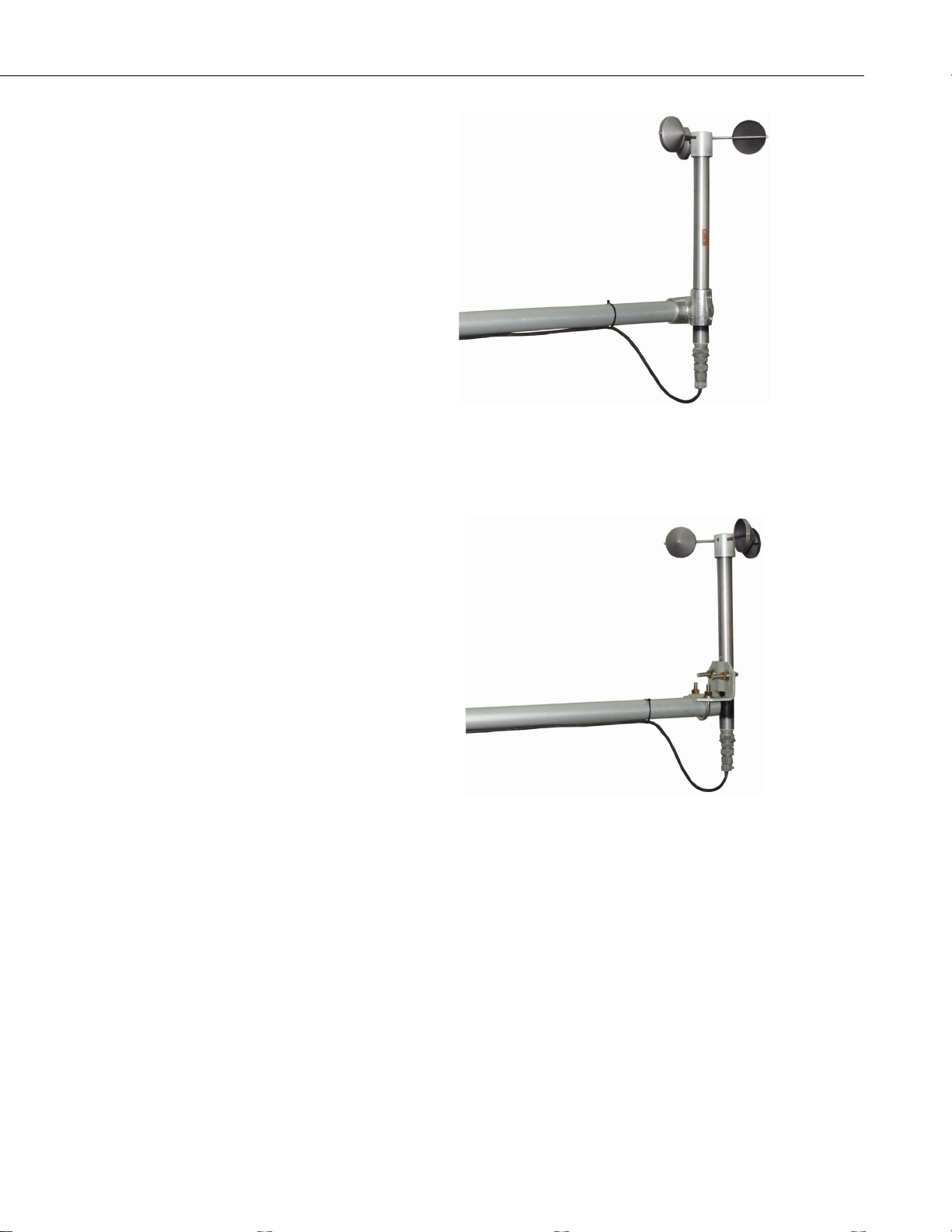
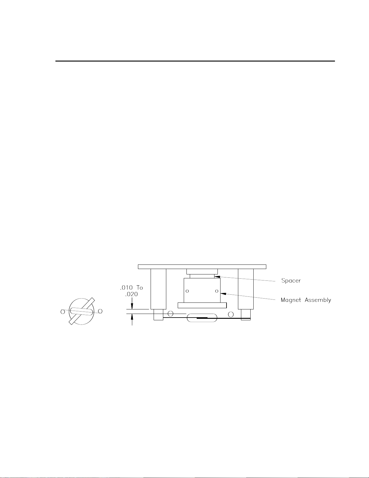
Mount the 019ALU or CM200 series crossarm to the tripod or tower. Orient
the crossarm north-south, with the 3/4” Nu-Rail or CM220 on the north end.
Insert the base of the 014A into the Nu-Rail or CM220 (Figures 3-1, 3-2) and
tighten the set screws on the Nu-Rail, or U-bolts on the CM220 (do not over
tighten).
Attach the sensor cable to the connector on the 014A. Make sure the
connector is properly keyed, and finger-tighten the knurled ring. Route the
sensor cable along the underside of the crossarm to the tripod/tower, and to the
instrument enclosure. Secure the cable to the crossarm and tripod/tower using
cable ties.
2
Page 7
Met-One 014A Wind Speed Sensor
FIGURE 3-1. 014A Mounted on a CM200 Series Crossarm
with PN 1049 (or 019ALU Crossarm)
4. Wiring
FIGURE 3-2. 014A Mounted on a CM200 Series Crossarm
with CM220
Connections to Campbell Scientific dataloggers are given in Table 4-1. When
Short Cut for Windows software is used to create the datalogger program, the
sensor should be wired to the channels shown on the wiring diagram created
by Short Cut.
3
Page 8

Met-One 014A Wind Speed Sensor
TABLE 4-1. Connections to Campbell Scientific Dataloggers
Pulse Channels
Color
Wire Label
CR800
CR850
CR5000
CR3000
CR1000
CR510
CR500
CR10(X)
21X
CR7
CR23X
CR200(X)
Black Signal Pulse Pulse Pulse P_SW
White Signal Reference
Clear Shield
G
G
A control port may also be used to measure the 014A. With this option the
white wire is connected to the 5V terminal. Please note that the control port
method cannot be used with a CR200(X), CR500, CR510, CR7, 21X, or CR10
datalogger.
TABLE 4-2. Connections to Campbell Scientific Dataloggers
Control Ports
Color
Wire Label
CR800
CR850
CR5000
CR3000
CR1000
CR10X
CR23X
Black Signal C1-C8 C6-C8 C5-C8
White Signal Reference 5 V 5 V 5 V
Clear Shield
G
5. Programming
5.1 Wind Speed
4
This section is for users who write their own programs. A datalogger program
to measure this sensor can be created using Campbell Scientifics’ Short Cut
Program Builder software. You do not need to read this section to use Short
Cut.
Wind speed is typically measured with a pulse count instruction, using the
switch closure configuration. For dataloggers programmed with Edlog,
specify configuration code 22 to output frequency in Hertz.
The expression for wind speed (U) is:
U = MX + B
where
M = multiplier
X = number of pulses per second (Hertz)
B = offset
Page 9

Table 5-1 lists the multipliers (M) and offsets (Off) to obtain meters/second or
miles/hour when the pulse count instruction is configured to output the result
in Hz.
Model Meters/Second Miles/Hour
014A
*When configuration code 12 is used, the multiplier above is
divided by the execution interval in seconds.
5.2 Example Programs
5.2.1 Pulse Port Examples
The following CR1000 and CR10X programs use a pulse port to measure the
014A every 5 seconds. The programs store mean wind speed (in m/s) every 60
minutes. Wiring for the examples is given in Table 5-2.
Met-One 014A Wind Speed Sensor
TABLE 5-1. Wind Speed Multiplier
(With Configuration Code 22*)
M = 0.8000
Off = 0.447
M = 1.789
Off = 1.0
TABLE 5-2. Wiring for Pulse Port Example Programs
Color Description CR1000 CR10X
Black Signal P1 P1
White Signal Reference
Clear Shield
5.2.1.1 CR1000 Example Program
'CR1000
'Created by Short Cut (2.5)
'Declare Variables and Units
Public Batt_Volt
Public WS_ms
Units Batt_Volt=Volts
Units WS_ms=meters/second
'Define Data Tables
DataTable(Table1,True,-1)
DataInterval(0,60,Min,10)
Average(1,WS_ms,FP2,False)
EndTable
'Main Program
BeginProg
Scan(5,Sec,1,0)
'Default Datalogger Battery Voltage measurement Batt_Volt:
Battery(Batt_Volt)
G
G
5
Page 10

Met-One 014A Wind Speed Sensor
'014A Wind Speed Sensor measurement WS_ms:
PulseCount(WS_ms,1,1,2,1,0.8,0.447)
If WS_ms<0.457 Then WS_ms=0
'Call Data Tables and Store Data
CallTable(Table1)
NextScan
EndProg
5.2.1.2 CR10X Example Program
;{CR10X}
*Table 1 Program
01: 5.0000 Execution Interval (seconds)
1: Batt Voltage (P10)
1: 1 Loc [ Batt_Volt ]
2: Pulse (P3)
1: 1 Reps
2: 1 Pulse Channel 1
3: 22 Switch Closure, Output Hz
4: 2 Loc [ WS_ms ]
5: 0.8 Multiplier
6: 0.447 Offset
3: If (X<=>F) (P89)
1: 2 X Loc [ WS_ms ]
2: 4 <
3: 0.457 F
4: 30 Then Do
4: Z=F x 10^n (P30)
1: 0 F
2: 0 n, Exponent of 10
3: 2 Z Loc [ WS_ms ]
5: End (P95)
6: If time is (P92)
1: 0 Minutes (Seconds --) into a
2: 60 Interval (same units as above)
3: 10 Set Output Flag High (Flag 0)
7: Set Active Storage Area (P80)
1: 1 Final Storage Area 1
2: 101 Array ID
8: Real Time (P77)
1: 1220 Year,Day,Hour/Minute (midnight = 2400)
9: Average (P71)
1: 1 Reps
2: 2 Loc [ WS_ms ]
6
Page 11

Met-One 014A Wind Speed Sensor
5.2.2 Control Port Example Program
The following CR5000 program uses control ports to measure three 014A
anemometers. The program measures them every second and stores the mean
wind speed (in m/s) every 15 seconds.
‘CR5000 Series Datalogger
‘Wind Speed using TimerIO Instruction
‘Declare Variables and Units
Public J, WindSpeed(3)
‘Define Data Tables
DataTable(Test,1,-1)
DataInterval(0,15,Sec,10)
Average(3,WindSpeed(),IEEE4,False)
EndTable
‘Define Subroutines
‘Sub
‘Enter Sub instructions here
‘EndSub
‘Main Program
BeginProg
Scan (1,Sec,0,0)
‘Measure the WindSpeed Profile 014A, 3 anemometers connected to C4, C5, C6 ports
TimerIO (WindSpeed(1),11000111,00222000,100,0) ‘Frequency on falling edge
‘Convert measurement to m/s
For j = 1 to 3
WindSpeed(j) = 0.447 + WindSpeed(j)/1.25
Next j
CallTable Test
Next Scan
End Prog
6. Maintenance
6.1 Suggested Maintenance Schedules
6.1.1 6-12 Month Periodic Service
Visually inspect the anemometer cups for cracks and breaks, and make sure
that each arm is securely attached to the cup assembly hub. Also check to see
that the vent hole, located at the base of the sensor, is unobstructed.
Special caution is advised under adverse conditions of high winds, heat, and/or
sandy areas. Look for abrupt stopping of the cup assembly with slow cup
rotation. If this occurs, the bearings may need to be replaced.
7
Page 12

Met-One 014A Wind Speed Sensor
6.1.2 12-24 Month Service
Replace sensor bearings.
6.1.3 24-36 Month Service
A complete factory overhaul of the sensor is recommended. Contact Met-One
directly for Wind Speed sensor repair and recalibration service. This repair
and calibration service includes disassembly and detailed inspection of all
moving mechanical parts and all electronic components. Service includes
replacement of bearings, shaft, and set screws as well as a functional test of the
sensor. Charges above the basic service charge may be added for replacement
of additional materials.
Met-One Instruments Inc.
479 California Avenue
Grants Pass, OR 97526
(541) 471-7111
FAX (541) 479-3057
7. Troubleshooting
8. References
Symptom: No wind speed
1. Check that the sensor is wired to the Pulse channel specified by the Pulse
count instruction.
2. Disconnect the sensor from the datalogger and use an ohm meter to check
the reed switch. The resistance between the white and black wires should
vary from infinite (switch open) to less than 1 ohm (switch closed) as the
cup wheel is slowly turned.
3. Verify that the Configuration Code (Switch Closure, hertz), and
Multiplier and Offset parameters for the Pulse Count instruction are
correct for the datalogger type.
Symptom: Wind speed does not change
1. For the dataloggers that are programmed with Edlog, the input location
for wind speed is not updated if the datalogger is getting “Program Table
Overruns”. Increase the execution interval (scan rate) to prevent
overruns.
The following references give detailed information on siting wind speed and
wind direction sensors.
8
EPA, 1989: Quality Assurance Handbook for Air Pollution Measurements
System, Office of Research and Development, Research Triangle Park, NC,
27711.
Page 13

Met-One 014A Wind Speed Sensor
EPA, 1987: On-Site Meteorological Program Guidance for Regulatory
Modeling Applications, EPA-450/4-87-013, Office of Air Quality Planning
and Standards, Research Triangle Park, NC 27711.
The State Climatologist, 1985: Publication of the American Association of
State Climatologists: Height and Exposure Standards, for Sensors on
Automated Weather Stations, vol. 9, No. 4.
WMO, 1983: Guide to Meteorological Instruments and Methods of
Observation, World Meteorological Organization, No. 8, 5th edition, Geneva,
Switzerland.
9
Page 14

Met-One 014A Wind Speed Sensor
10
Page 15
Appendix A. Sensor Maintenance
A.1 Reed Switch Replacement Procedure
To verify parts and locations, refer to the parts diagram (Figure A-3) and the
parts list (Table A-1).
A. Remove sensor from mounting arm and disconnect cable.
B. Remove the cup assembly.
C. Remove the three phillips screws at the top of the sensor and lift out the
bearing mount assembly.
D. Unsolder the leads of the reed switch and remove the switch from the two
mounting terminals, see the parts diagram.
E. Solder the new switch onto the sides of the switch mount terminals (form
a loop in the relay leads to obtain proper lead length -- DO NOT CUT
THE RELAY LEADS.) Measure the distance between the bottom of the
rotating magnet and the top of the switch envelope, as shown in Figure
A-1. The spacing should measure between 0.01 and 0.02 inches.
F. Spin the shaft to verify switch operation by listening for a faint sound of
the switch closure. If the switch cannot be heard, move the switch slightly
closer to the magnet assembly.
G. Reassemble sensor.
FIGURE A-1. Reed Switch Assembly
A.2 Bearing Replacement Procedure
The bearings used in the 014A Sensor are special stainless steel ball bearings
with a protective shield. Bearings are lubricated and sealed. DO NOT
LUBRICATE BEARINGS AS THE LUBRICATION WILL ATTRACT
DUST AND INHIBIT BEARING OPERATION.
A. Follow steps 6.2 A, B, and C in reed switch replacement procedures.
B. Loosen set screws in magnet assembly, lift shaft and collar up and out of
bearing mount. Be sure to retain lower spacer.
A-1
Page 16

Appendix A. Sensor Maintenance
C. Insert a right-angle type of tool, such as an allen wrench, into bearing.
D. Install new bearings. Be careful not to introduce dirt particles into
E. Reassemble the sensor in reverse order. Be sure to include spacers over
Cock it slightly to one side and remove both bearings.
bearings. CLEAN HANDS ONLY! DO NOT ADD LUBRICATION
OF ANY KIND.
the bearings when replacing the shaft in the bearing mount. After the
magnet assembly has been tightened, a barely perceptible amount of
endplay should be felt when the shaft is moved up and down.
A-2
FIGURE A-2. Cable Diagram
Page 17

Appendix A. Sensor Maintenance
FIGURE A-3. Parts Diagram
A-3
Page 18

Appendix A. Sensor Maintenance
Item Part No. Description Qty./Assy
1 1011685-2 Housing 1
2 101685-4 Bearing Mount 1
3 101685-7 Collar 1
4 101715 Magnet Assembly 1
5 101812 Assy, Cup (Alum) 1
6 101898 Bearing 2
7 86001 Shaft 1
8 101048-2 Label 1
9 1812-1 Assy, Cup (Lexan) 1
10 880160 Switch, Reed 1
11 500295 Conn, 2 Pin Male 1
12 510020 Cap 1
13 970062 Terminal 2
14
15 9980480 Wire, 22G Red 18"
16 980445 Wire, 22GA Black 18"
17
18
19 860250 Spacer 2
20
21 601250 SCR, SET A/H C/P 4-40x1/8 4
22 601230 SCR,FLT HD PHIL 4-40x1/4 3
23 601680 SCR,SET A/H C/P 8-23x3/8 2
24
25 995120 Adhesive, (RTV 108) A/R
26 995100 Adhesive, Epoxy (907) A/R
27 995425 Locite 222-21 A/R
28 995060 Adhesive, Silicone 5 ml
29 995430 Locite 290-21 A/R
30 400010 Cable, 2 Cond. REF
31 500372 Conn, 2 Pin Socket REF
32 480500 Clamp REF
TABLE A-1. Met-One Parts List
Reproduced by Campbell Scientific, Inc.
A-4
Page 19

Appendix B. Theory of Operation
B.1 Mechanical
The anemometer cup assembly consists of three aluminum cups mounted on a
cup assembly hub. A stainless steel shaft, which rotates on precision-sealed
ball bearings, connects the cup assembly to a magnet assembly. When the
shaft is rotated, the turning magnet assembly causes a reed switch to close.
There are two contacts (reed switch closures) per revolution. The frequency of
closures is linear from threshold to 45 m/s.
B.2 Calibration
The 014A Anemometer has a threshold speed of 0.447 m/s and follows the
equation:
V = 0.447 + f/1.250 where
V = wind speed (m/s), and
f = output frequency (hz,)
or, V = 1.0 + f/0.5589
where V = wind speed (mph), and
f = output frequency (hz.)
B-1
Page 20

Appendix B. Theory of Operation
B-2
Page 21

Page 22

Campbell Scientific Companies
Campbell Scientific, Inc. (CSI)
815 West 1800 North
Logan, Utah 84321
UNITED STATES
www.campbellsci.com • info@campbellsci.com
Campbell Scientific Africa Pty. Ltd. (CSAf)
PO Box 2450
Somerset West 7129
SOUTH AFRICA
www.csafrica.co.za • cleroux@csafrica.co.za
Campbell Scientific Australia Pty. Ltd. (CSA)
PO Box 444
Thuringowa Central
QLD 4812 AUSTRALIA
www.campbellsci.com.au • info@campbellsci.com.au
Campbell Scientific do Brazil Ltda. (CSB)
Rua Luisa Crapsi Orsi, 15 Butantã
CEP: 005543-000 São Paulo SP BRAZIL
www.campbellsci.com.br • suporte@campbellsci.com.br
Campbell Scientific Canada Corp. (CSC)
11564 - 149th Street NW
Edmonton, Alberta T5M 1W7
CANADA
www.campbellsci.ca • dataloggers@campbellsci.ca
Campbell Scientific Centro Caribe S.A. (CSCC)
300 N Cementerio, Edificio Breller
Santo Domingo, Heredia 40305
COSTA RICA
www.campbellsci.cc • info@campbellsci.cc
Campbell Scientific Ltd. (CSL)
Campbell Park
80 Hathern Road
Shepshed, Loughborough LE12 9GX
UNITED KINGDOM
www.campbellsci.co.uk • sales@campbellsci.co.uk
Campbell Scientific Ltd. (France)
3 Avenue de la Division Leclerc
92160 ANTONY
FRANCE
www.campbellsci.fr • info@campbellsci.fr
Campbell Scientific Spain, S. L.
Avda. Pompeu Fabra 7-9, local 1
08024 Barcelona
SPAIN
www.campbellsci.es • info@campbellsci.es
Please visit www.campbellsci.com to obtain contact information for your local US or International representative.
 Loading...