

Page 1

012 WEATHER STATION
OPERATOR'S MANUAL
COPYRIGHT (c) 1989, 1991 CAMPBELL SCIENTIFIC, INC.
REVISION: 9/91
Page 2

This is a blank page.
Page 3

WARRANTY AND ASSISTANCE
The 012 WEATHER STATION is warranted by CAMPBELL SCIENTIFIC, INC. to be free from defects in
materials and workmanship under normal use and service for twelve (12) months from date of shipment
unless specified otherwise. Batteries have no warranty. CAMPBELL SCIENTIFIC, INC.'s obligation under
this warranty is limited to repairing or replacing (at CAMPBELL SCIENTIFIC, INC.'s option) defective
products. The customer shall assume all costs of removing, reinstalling, and shipping defective products
to CAMPBELL SCIENTIFIC, INC. CAMPBELL SCIENTIFIC, INC. will return such products by surface
carrier prepaid. This warranty shall not apply to any CAMPBELL SCIENTIFIC, INC. products which have
been subjected to modification, misuse, neglect, accidents of nature, or shipping damage. This warranty
is in lieu of all other warranties, expressed or implied, including warranties of merchantability or fitness for
a particular purpose. CAMPBELL SCIENTIFIC, INC. is not liable for special, indirect, incidental, or
consequential damages.
Products may not be returned without prior authorization. To obtain a Returned Materials Authorization
(RMA), contact CAMPBELL SCIENTIFIC, INC., phone (435) 753-2342. After an applications engineer
determines the nature of the problem, an RMA number will be issued. Please write this number clearly on
the outside of the shipping container. CAMPBELL SCIENTIFIC's shipping address is:
CAMPBELL SCIENTIFIC, INC.
RMA#_____
815 West 1800 North
Logan, Utah 84321-1784
CAMPBELL SCIENTIFIC, INC. does not accept collect calls.
Non-warranty products returned for repair should be accompanied by a purchase order to cover the repair.
815 W. 1800 N.
Logan, UT 84321-1784
USA
Phone (435) 753-2342
FAX (435) 750-9540
www.campbellsci.com
Campbell Scientific Canada Corp.
11564 -149th Street
Edmonton, Alberta T5M 1W7
CANADA
Phone (780) 454-2505
FAX (780) 454-2655
Campbell Scientific Ltd.
Campbell Park
80 Hathern Road
Shepshed, Loughborough
LE12 9GX, U.K.
Phone +44 (0) 1509 601141
FAX +44 (0) 1509 601091
Page 4

This is a blank page.
Page 5

SPECIAL OPERATING NOTES
1. Check the shipping list in the front of the
manual and make sure that all the parts
checked off the list are with the weather station.
If any parts are missing please contact
Campbell Scientific, Inc. 435-753-2342.
2. When connecting the battery avoid shorting
the battery to the weather station base (Section
2.5.1).
3. Damage to the electronics will occur if
moisture builds up inside the weather station. A
moisture detection sensor is used to detect
excessive humidity levels. This reading must
be monitored and corrective action taken if
moisture is detected (Section 4).
4. The hex bolts sealing the squeeze plates at
each end of the canister must be tightened
every spring and fall to maintain seal integrity
(Section 4).
Page 6

This is a blank page.
Page 7

012 WEATHER STATION
TABLE OF CONTENTS
PAGE
SECTION 1. WEATHER STATION DESCRIPTION
1.1 Standard Sensors ...................................................................................................................1-1
1.2 Data Retrieval Options ............................................................................................................1-1
1.3 Power Supply Options.............................................................................................................1-1
SECTION 2. WEATHER STATION INSTALLATION
2.1 Site Selection ..........................................................................................................................2-1
2.2 Tools and Supplies..................................................................................................................2-1
2.3 Foundation Construction .........................................................................................................2-2
2.4 Weather Station Assembly......................................................................................................2-4
2.5 Power Supply Installation ........................................................................................................2-6
2.6 Data Retrieval Option Installation............................................................................................2-9
2.7 Sensor Verification Using the CR10KD Keyboard Display....................................................2-14
2.8 Setting the Clock with the CR10KD Keyboard Display .........................................................2-14
2.9 Setting Flag 1 to Enable Soil Temperature Measurements ..................................................2-16
SECTION 3. PROGRAMMING
3.1 Programming Sensor Measurements .....................................................................................3-1
3.2 PC208 Datalogger Support Software......................................................................................3-5
SECTION 4. MAINTENANCE
4.1 Moisture in Canister ................................................................................................................4-1
4.2 Rain Gage ...............................................................................................................................4-1
4.3 Solar Radiation........................................................................................................................4-1
4.4 Wind Speed and Direction ......................................................................................................4-1
4.5 Temperature and Relative Humidity Probe.............................................................................4-2
4.6 Battery Voltage........................................................................................................................4-2
SECTION 5. TROUBLESHOOTING
5.1 Sensor Troubleshooting ..........................................................................................................5-1
5.2 Datalogger Troubleshooting ....................................................................................................5-1
APPENDICES
Apdx A. Program Listing ...................................................................................................................... A-1
Apdx B. Sensor Specifications and Schematics .................................................................................. B-1
TABLES
2.2-1 Tool Requirements..................................................................................................................2-1
2.2-2 Materials Requirements for Constructing Foundation.............................................................2-1
2.6 Rad Modem Connections......................................................................................................2-10
2.7-1 Sensor Verification ................................................................................................................2-16
2.8 Sequence of Time Parameters in *5 Mode ...........................................................................2-16
3.0 012 Standard Program Outputs ..............................................................................................3-1
3.1 Parameters for Sensor Measurement Instruction ...................................................................3-2
I
Page 8

012 TABLE OF CONTENTS
FIGURES
2.1 Effect of Structure on Wind Flow ........................................................................................... 2-1
2.3-1 012 Foundation Construction ................................................................................................. 2-2
2.3-2 012 Weather Station with Solar Panel ................................................................................... 2-3
2.3-3 Template and Anchor Bolt Assembly ..................................................................................... 2-3
2.4-1 012 Weather Station Assembly.............................................................................................. 2-4
2.4-2 Wind Set Alignment................................................................................................................ 2-5
2.5-1 Battery/Solar Panel Connections ........................................................................................... 2-7
2.5-2 Battery/AC Charging Connections ......................................................................................... 2-8
2.6-1 RAD Modem Connections.................................................................................................... 2-10
2.6-2 Phone Modem Connections................................................................................................. 2-11
2.6-3 012 Weather Station with Radio Antenna ............................................................................ 2-12
2.6-4 012 Weather Station with Storage Module........................................................................... 2-13
2.8 Day of Year Calendar........................................................................................................... 2-15
5.2 CR10 Serial I/O Connector ....................................................................................................5-2
B.1 Sensor Channel Assignments and Connections .................................................................... B-1
B.2 Sensor Wind Direction ........................................................................................................... B-2
B.3 Sensor Rain Gage.................................................................................................................. B-3
B.4 Sensor Pyranometer ..............................................................................................................B-4
B.5 Sensor Temperature and RH ................................................................................................. B-5
B.6 Sensor Air Temperature......................................................................................................... B-6
B.7 Sensor Soil Temperature ....................................................................................................... B-7
B.8 Sensor Wind Speed ...............................................................................................................B-8
II
Page 9

SECTION 1. WEATHER STATION DESCRIPTION
The 012 Weather Station is designed to reduce the cost and logistics of routine climatological
monitoring. Installation is simplified through a modular design and prewired sensors. This manual
covers installation, sensor options, power supply options, programming, maintenance, and trouble
shooting.
1.1 STANDARD SENSORS
Sensors with preassigned channels include:
• wind speed
• wind direction
• temperature
• relative humidity
• solar radiation
• rainfall
• soil temperature
• moisture detection
Section 3 explains the channel assignments
and how to program the weather station.
1.2 DATA RETRIEVAL OPTIONS
Telecommunication options include phone,
short haul, and radio. Different options require
different wiring connections in the base of the
weather station. Section 2 covers various
modem options.
When telecommunications are not required,
storage modules (SM192, SM716) may be used
for on-site data retrieval.
1.3 POWER SUPPLY OPTIONS
The base of the weather station is designed to
fit a user supplied 12 VDC deep cycle marine
battery. Power cables supplied with the station
fit 3/8" diameter battery posts. The battery may
be periodically replaced with a freshly charged
one, or it may be charged in place with either
the PS12 charging regulator and 110 VAC to 16
VAC transformer, or the MSX10R solar panel.
CSI offers a 7 Amp-hour rechargeable battery
which should be continuously charged due to its
small capacity.
1-1
Page 10

This is a blank page.
Page 11

SECTION 2. WEATHER STATION INSTALLATION
FIGURE 2.1. Effect of Structure on Wind Flow
2.1 SITE SELECTION
The site, including its climate and topography,
should represent the general area being
measured. Also avoid man-made or natural
obstructions such as buildings, asphalt parking
lots, and trees. General sensor placement
guidelines are:
WIND SENSORS
Trees, buildings, or other structures can greatly
influence wind speed and direction
observations. As a rule of thumb, a structure
will disturb the air flow an upwind distance of
about twice the height of the structure; a
downwind distance of about six times the height
of the structure and a vertical distance of up to
twice the height of the structure. (Figure 2.1).
TEMPERATURE AND RELATIVE
HUMIDITY PROBE
The radiation shield provides protection from
direct sunlight and rain. The shield does not
protect against irrigation water which may be
sprayed up into the plates. If the RH chip goes
through wetting and drying cycles, the active
sensing material separates from the substrate,
damaging the sensor.
RAIN GAGE
Do not place the rain gage where it may catch
irrigation water. When possible, there should
be no obstructions in a 45
of the gage.
o
line rising off the lip
SOLAR RADIATION
The pyranometer should be located so it is not
shadowed by surrounding objects.
TABLE 2.2-1. Tool Requirements
• sledgehammer • compass
• open end wrench 3/4" • rag
• trowel (for cement) • shovel
• tape measure • flat metal file
• dozen 16 penny nails • wheelbarrow
• wire strippers • level
• screw driver, regular head • hammer
• screw driver, phillips head • wood saw
• screw driver, regular head thin blade
2.2 TOOLS AND SUPPLIES
An itemized list of weather station components
included in the shipment is found in the front of
the manual. Tables 2.2-1 and 2.2-2 list the
tools and supplies, respectively, required to
install the weather station.
TABLE 2.2-2. Materials Requirements for
Constructing Foundation
5 80 lb. sacks of sakrete
1 8' x 2" x 4" lumber
* 11" x 11" metal template
* 4 1/2" x 12" stainless steel anchor bolts
* 1" conduit elbow
1 1/4" diameter x 3 1/2' long pipe (solar
panel systems only)
*CSI supplied
2-1
Page 12

SECTION 2. WEATHER STATION INSTALLATION
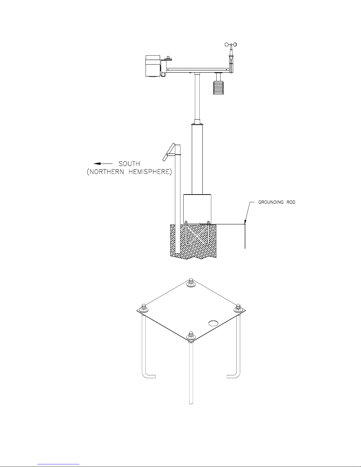
2.3 FOUNDATION CONSTRUCTION
The 012 Weather Station mounts on a cement
foundation as shown in Figures 2.3-1 and 2.3-2.
CSI provides a (1) metal template for locating
the anchor bolts and conduit in the base, (2)
four anchor bolts with two nuts each for leveling
the station, and (3) a conduit for
communication wire entry/exit at the base.
Step 1 - Dig an 18" square hole that is 12-13"
deep. These estimates are for heavy soils only;
light, shifting, or sandy soils require a deeper
base (and more cement). Excavate a slot for
the conduit elbow at about 9" below the surface
on the side where the communication cables
will enter. The slot should be oversized, making
it easier to install the conduit (Step 3).
Step 2 - Construct a wood form for the above
ground portion of the foundation. If the surface
area of the hole is 18", cut two 18" and two
21.5" boards from the 8' 2x4. Nail the boards
together to make an 18" (inside dimension)
square form. Center the form over the hole.
Step 3 - Three cubic feet of cement are
required to fill a 18" x 18" x 16" deep hole. This
amounts to approximately five (5) eighty pound
(80 lb.) sacks of sakrete. Mix the cement. Stuff
a rag into one end of the conduit elbow to
prevent cement from clogging the conduit.
While holding the conduit in place pour the
cement. Examine the template to judge where
to position the top of conduit. About 1.5 inches
of conduit should be exposed above the cement
surface.
Step 4 - While the cement is setting, assemble
the template and anchor bolts as shown in
Figure 2.3-3. Set the anchor bolts and template
in the cement so the conduit is coming through
the conduit hole in the template. The threaded
end of the anchor bolts should extend a
minimum of 1.75" above the top of the concrete.
This will allow the template to rest on the lower
set of nuts about 1" above the surface of the
concrete (Figure 2.3-1). Adjustment of the
lower set of nuts will allow you to level the
template and later the 012 weather station. Do
not remove the template. It is used as the
bottom for the pedestal base when the weather
station is assembled.
Step 5 - Weather stations using a solar panel
for charging the battery need to insert a user
supplied 1 1/4" pipe into the cement pad (Figure
2.3-2).
FIGURE 2.3-1. 012 Foundation Construction
2-2
Page 13
SECTION 2. WEATHER STATION INSTALLATION
FIGURE 2.3-2. 012 Weather Station with Solar Panel
FIGURE 2.3-3. Template and Anchor Bolt Assembly
2-3
Page 14

SECTION 2. WEATHER STATION INSTALLATION
FIGURE 2.4-1. 012 Weather Station Assembly
2.4 WEATHER STATION ASSEMBLY
The following instructions describe the
installation of the 012 weather station. All steps
except those marked with an asterisk (*) are
shown in Figure 2.4-1.
Before assembling the threaded ends of the
mast, apply the teflon pipe dope provided with
the weather station to prevent the aluminum
from galling.
2-4
Step 1 Thread the cables from the canister
through the mast and hand tighten the mast to
the canister. Do not twist the cables.
Step 2. Remove the crossarm cover.
Thread the cables through the center hole of
the crossarm and screw the crossarm to the
mast.
Page 15

SECTION 2. WEATHER STATION INSTALLATION
CAUTION: Over-tightening the mast will
cause excessive torque.
Step 3 Mount the weather station on the
cement pad aligning the conduit with the conduit
notch in the bottom of the pedestal. Vertically
plumb the weather station by adjusting the
upper and lower nuts that secure the pedestal
base to the anchor bolts.
*
Step 4 (Figure 2.4-2) Tighten the crossarm
and mast as much as possible while aligning
the crossarm north-south. The crossarm end,
with the 1 5/8" hole on the underside, must be
pointed north. Use of a compass is
recommended as the crossarm orientation
affects the accuracy of the wind direction
measurement.
Step 5 Mount the wind sensors on the north
end of the crossarm using the brackets
provided. The windset crossarm should be
oriented east-west, with the wind direction
sensor oriented to the east (Figure 2.4-2).
For stations which measure wind speed only,
the wind speed sensor may be mounted on
either end of the windset crossarm. A small
square metal piece is provided to fill in the area
left vacant for the wind direction sensor.
Step 6 Mount the solar radiation and rain
gage sensors on the south end of the crossarm.
NOTE: Insert the sensor cables through
the grommeted slot before attaching
sensors to the crossarm.
Level the radiation sensor using the 3
adjustment screws and the fixtures bubble level.
NOTE: Accurate radiation measurements
require accurate leveling.
Remove the top of the rain gage and make sure
that the magnet is not holding the bucket at a
dead center position. Manually tip the bucket,
checking that it tips freely to both sides.
Replace and level the the lid.
Step 7 Mount the radiation shield into the 1
5/8" diameter hole on the underside of the
crossarm. Put the Temperature and Relative
Humidity sensor into the radiation shield. Make
sure that the temperature and RH sensor is
properly seated into the radiation shield.
NOTE: For weather stations with a
temperature sensor only, the temperature
sensor is mounted in the radiation shield.
FIGURE 2.4-2. Wind Set Alignment
2-5
Page 16

SECTION 2. WEATHER STATION INSTALLATION
Step 8 Attach the lightning rod to the 1 1/4"
sleeve on the underneath side of the crossarm.
*
Step 9 The serial (I/O) cable is mounted on
the underside of the crossarm, near the mast.
Remove the screws, insert the 9 pin D shaped
connector, and then replace the screws.
NOTE: The cover lid is held in place by a
long bolt. Make sure that the cover plate is
in place before tightening the screws.
Step 10 Route the windset cables through
the bottom of the crossarm. Make sure the
cables pass through the grommeted slot.
*
Step 11 Observe the labeling on the sensor
leads and connect the sensor cables to the
appropriate canister cables. Arrange the
connectors so they don't interfere with the
crossarm cover. Tie down all sensor leads with
the nylon ties provided in the ends of the crossarm.
Replace the crossarm cover using the six screws.
*
Step 12 Double check the weather station to
make sure that the solar radiation and rain gage
sensors are level. Also, check to see that the
wind direction sensor is mounted on the east
side of the crossarm.
Step 13 Proper grounding of the station is
required to minimize damage from transients
caused by lightning strikes or other voltage
surges. Drive the copper plated ground rod into
the earth adjacent to the weather station and
attach the ground rod clamp. A 12 AWG green
grounding wire is connected to a ground lug on
the base. Connect the free end of the green
wire to the ground rod clamp. This important
step grounds the communications modem, the
weather station, and the CR10 datalogger.
*
Step 14 The soil temperature probe is an
optional sensor. Connections are made in the
base for ease of installation into the soil.
2.5 POWER SUPPLY INSTALLATION
2.5.1 BATTERY INSTALLATION
NOTE: The 012 Weather Station base is at
power ground. When installing the battery
on the template inside the base, take care
not to short the positive post of the battery
to the base.
The battery may be continuously charged or
periodically exchanged with a fresh one.
Following the procedure below, batteries may
be replaced without losing power to the station.
To install a battery, locate the terminal block
inside the pedestal base where power supply
connections are made (Figures 2.5-1 and 2.5-
2). Connect the battery to the terminal labeled
"Batt 12V". The power Sonic battery supplied
by CSI is prewired with red lead positive and
black lead negative. The Power Sonic should
be continuously changed due to its smaller
capacity, 6Ahr.
Connect a user supplied battery with one of the
two power cables provided. Connect the cable
to the "BATT 12V" red positive, black negative
terminal block first then connect to the battery.
Do not connect a battery to the AUX BATT 12V
Terminal when using the PS12 charging
regulator as explained below.
Battery Replacement The battery should be
replaced when discharged below 11 volts
(Sections 2.7, 4.6). The second set of battery
cables are provided for exchanging batteries
without interrupting power to the CR10
Datalogger. Leave the old battery connected
until the new battery is connected. Connect the
cable to the "AUX BATT 12V" terminals first,
then the circular lugs of the battery. Disconnect
and remove the old battery. Store the cable
until needed for the next battery change. Never
leave a battery cable connected to the power
strip with the circular lugs dangling.
WARNING: If the 12V power is
disconnected from the weather station the
data in the datalogger is lost.
2.5.2 CHARGING OPTIONS
CSI offers the PS12 12V Charger with 110
VAC to 16 VAC transformer or the MSX10R
Solar Panel for continuously charging the
battery power supply. The charging source
must be connected to the terminals labeled
"INPUT EXTERNAL CHARGING SOURCE". If
ordered with the weather station, the PS12 is
pre-mounted in the base. The MSX10R Solar
Panel is used when AC power is not available.
NOTE: The "EXTERNAL CHARGING
SOURCE" connects only to the "BATT 12V"
terminals. The "AUX BATT 12V" terminals
are not included in the charging circuit.
2-6
Page 17

SECTION 2. WEATHER STATION INSTALLATION
PS12
For safety reasons, DO NOT mount the 110
VAC supply directly to the weather station.
Mount the transformer external to the stations
and run 16 VAC to the station (Figure 2.5-2).
The maximum distance for the 16 VAC using an
18 awg cable is 2000 ft. The electrical
connections should be done in accordance with
the National, State, and Local electrical codes.
Solar Panel
The solar panel is mounted (Figure 2.3-2) on
the south side of the weather station (northern
hemisphere only) and connects to the terminals
labeled "INPUT EXTERNAL CHARGING
SOURCE" (Figure 2.5-1).
FIGURE 2.5-1. Battery/Solar Panel Connections
2-7
Page 18

SECTION 2. WEATHER STATION INSTALLATION
FIGURE 2.5-2. Battery/AC Charging Connections
2-8
Page 19

SECTION 2. WEATHER STATION INSTALLATION
2.6 DATA RETRIEVAL OPTION
INSTALLATION
The four options available for data collection are
the Rad Modem, DC112 Phone Modem, RF95
Radio Frequency modem, and storage modules.
Any modem ordered with the station is premounted in the canister. Refer to the specific
manuals of each device for technical information
on the modems and storage modules.
2.6.1 RAD MODEMS
Figure 2.6-1 shows the RAD modem terminal
block located inside the pedestal base. The
communication cable is connected between the
modem at the PC and the weather station
according to the labels shown in Table 2.6. The
communications cable connecting the station to
the computer must be two twisted pairs (4
conductors) and suitable for burial. Examples
are *Anixter part number F-02P22BPN (Rodent
Proof) or *Belden part number 1048A.
TABLE 2.6. Rad Modem Connections
SRM-6A at PC Base of Weather Station
+XMT +XMT
-XMT -XMT
+RCV +RCV
-RCV -RCV
*Anixter *Belden
4711 601 FRD P.O. Box 1980
Skokie, IL 60076 Richmond, IN 47375
708-677-2600 1-800-BELDEN1
2.6.2 DC112 PHONE MODEM
Figure 2.6-2 shows the phone modem terminal block
located inside the pedestal base. A copper shielded,
burial phone cable should enter the weather station
pedestal via the conduit. Strip 1 7/8 inches of the
insulation off the cable without cutting the copper
shield. Strip the shield 1 1/2", insert the cable into
the ground lug mounted on the center terminal, and
tighten it onto the copper shield.
CAUTION: Do not over tighten ground lug
or damage to the phone line will occur.
Connect the RING signal (orange or blue wires)
to the terminal labeled RING and the TIP signal
(white/orange or white/blue wires) to the
terminal labeled TIP.
2.6.3 RF MODEM
Mount the antenna to the mast of the weather
station as shown in Figure 2.6-3. Fish the
connecting COAX cable through the grommeted
hole in the bottom of the cross arm adjacent at
the mast. Connect the cable to the antenna.
Take care not to kink the COAX cable or
damage will occur.
The RF95 Modem must be removed from the
canister to set the station ID number if the
switches have not been preset. Directions for
setting the ID switches are described in the
Radiotelemetry Network Applications Manual.
2.6.4 STORAGE MODULE SM192/SM716
The CR10 is programmed to automatically
transfer data when it detects that a storage
module is connected. The storage module is
brought to the site and connected to the CR10
as shown in Figure 2.6-4. Data transfer begins
within 5 seconds after making connections, and
ends a maximum of 55 seconds later. If an
SC90 Line Monitor is used, an LED turns on
and off when data transfer starts and stops,
respectively. Disconnect the storage module
and proceed to the office for data playback.
Never leave the storage module connected
to the weather station.
2-9
Page 20

SECTION 2. WEATHER STATION INSTALLATION
FIGURE 2.6-1. RAD Modem Connections
2-10
Page 21

SECTION 2. WEATHER STATION INSTALLATION
FIGURE 2.6-2. Phone Modem Connections
2-11
Page 22

SECTION 2. WEATHER STATION INSTALLATION
FIGURE 2.6-3. 012 Weather Station with Radio Antenna
2-12
Page 23

SECTION 2. WEATHER STATION INSTALLATION
FIGURE 2.6-4. 012 Weather Station with Storage Module
2-13
Page 24

SECTION 2. WEATHER STATION INSTALLATION
TABLE 2.7-1. Sensor Verification; Accessing CR10 Input Locations
Description Units
Battery Voltage
CR10 Temperature
Canister Moisture
Ambient Temperature
Ambient Temperature
*
**
Volts 1
o
0-1000 3
o
o
Relative Humidity %RH 6
Solar Radiation
1
kW/m
Wind Speed mph 8
Wind Direction
2
degree 9
Precipitation inches 10
Soil Temperature
*** o
Input Keyboard
Location Entry
*
6A
C2*62A
*
63A
C4*64A
F5*65A
*
2
7
66A
*
67A
*
68A
*
69A
*
610A
F11*611A
2.7 SENSOR VERIFICATION USING
THE CR10KD KEYBOARD DISPLAY
The following steps allow verification of the
sensor measurements performed every 10
seconds.
Connect the CR10KD Keyboard Display to the
serial I/O connector in the crossarm (refer to
Figure 2.6-4) using the Model SC12 cable.
Upon connection, the display activates, showing
meaningless numbers. Enter
should show LOG1. The sensor measurements
are stored in the CR10's Input Locations,
*
accessed through the
6 Mode; refer to the
keyboard entry column in Table 2.7-1. If you
get lost or make a mistake, start over by
*
entering
6. Once you are in *6 the A key may
be used to advance through the locations and
the B key may be used to backup through the
locations.
*
NOTE: Due to reverse polarity protection
diodes in the circuit, the battery voltage
measurement is approximately .7 volts
lower than the actual battery voltage.
Minimum operating voltage for the CR10 is
9.6 V.
**
WARNING: Readings above 200 indicate
high humidity inside the canister. The
canister must be opened and dried, and the
desiccant reactivated by heating at 250o for
12 hours.
*
0 and the display
1. Typical values should be between 300
(overcast) and 1000 (bright sunshine).
2. To check the wind vane, point it to the east
o
and compare new reading to 90
***
NOTE: Soil temperature readings are
.
made only if the CR10 User Flag #1 is set
high. Refer to Section 2.9 for details.
2.8 SETTING THE CLOCK WITH THE
CR10KD KEYBOARD DISPLAY
To set the year, day of year, and time, enter *5
and advance the display to the appropriate
window (refer to Table 2.8). Key in the desired
value and enter it by pressing the A key. When
a new value for hours and minutes is entered,
the seconds are set to zero and current time is
again displayed. Figure 2.8 shows a day of year
calendar.
TABLE 2.8. Sequence of Time Parameters in
*5 Mode
Key Display
*5 :HH:MM:SS Display current time
A 05:XX Display/enter year
A 05:XXXX Display/enter day of
Description
in hours, minutes,
and seconds
year
2-14
A 05:HH:MM
Display/enter
hours:minutes in
military time
Page 25

SECTION 2. WEATHER STATION INSTALLATION
During leap year add 1 to day 60 (March 1st) through day 365.
FIGURE 2.8. Day of Year Calendar
An example of entering year 89, day 100, and
time 1437 is shown below:
Key Display
*5 Current if time has not been set,
Description
CR10 time time since power up
is shown
A 05:XX display year
89 05:89 key in correct year
A 05:XXXX enter correct year and
display day of year
100 05:100 key in correct day of year
A 05:HH:MM enter correct day of year
and display hours and
minutes
1437 05:14:37 key in correct time
A :14:37:00 enter correct time and
display time
Verify that the year, day and time are entered
correctly by entering the
*5 mode and advancing
to each location:
Key Display
Description
*5 :14:37:15 display hour, minutes,
and seconds
A 05:89 display year
A 05:100 display day of year
A 05:14:37 display hour and minutes
A :14:37:20 return to the original
display of hours,
minutes, and seconds
Leave the clock mode (
*5) and return to the Log
Mode by keying *0.
2-15
Page 26

SECTION 2. WEATHER STATION INSTALLATION
2.9 SETTING FLAG 1 TO ENABLE SOIL
TEMPERATURE MEASUREMENTS
The optional soil temperature probe is read only
if Flag 1 is set high.
To set Flag 1, enter * 6 11 A. The display reads
11:XXXXX, where XXXXX represents the
contents of Input Location 11. Press the D key
and the display reads 00:000000. The zeros,
from left to right, show that Flags 1 through 8
are not set. To set Flag 1 press 1. The display
reads 10:000000. Return to Input Location 11
by pressing the A key. A soil temperature
reading appears in 10 seconds or less.
If the soil temperature measurement is
performed when no probe is connected, the
value -53.46 is recorded. Follow the same
procedure as outlined above to reset Flag 1 and
disable the measurement.
2-16
Page 27

SECTION 3. PROGRAMMING
The CR10 Measurement and Control Module begins executing the program stored in its PROM when
power is connected to the weather station. This "program-on-power-up" function is not found in standard
CR10s where users enter their own programs. Users desiring additional sensors or outputs different
from this "standard" program may create their own program and overwrite the existing one.
The resident program listed in Appendix A measures wind speed, wind direction, air temperature,
relative humidity, solar radiation, and rain every 10 seconds. Soil temperature is measured only if
enabled by the user; Flag 1 = 1 (Section 2.9).
The program stores hourly, daily and conditional data as shown below.
TABLE 3-1. 012 Standard Program Outputs
Hourly Output 24 Hour Output
01: Array ID 129 01: Array ID 139
02: Day 02: Day
03: Hour, Minute 03: Hour, Minute
04: Avg. Temperature (F) 04: Avg. Temperature (F)
05: Instantaneous RH (%) 05: Maximum Air Temperature (F)
06: Avg. Solar Radiation (kW/m
07: Avg. Wind Speed (mph) 07: Maximum Relative Humidity
08: Wind Speed Weighted Avg. Dir. 08: Minimum Relative Humidity
09: Standard Deviation of Wind Dir. 09: Avg. Solar Radiation (kW/m
optional (Flag 1 set high) 10: Maximum Wind Speed (mph)
10: Soil Temperature (F) 11: Avg. Wind Speed (mph)
Conditional Output
1 Minute Rain Fall Intensity 15: Maximum CR10 Temperature (C)
01: Array ID 124 16: Minimum CR10 Temperature (C)
02: Hour, Minute optional (Flag 1 set high
03: Rain Fall (inches) 17: Maximum Soil Temperature (F)
2
) 06: Minimum Air Temperature (F)
12: Total Rain Fall (inches)
13: Maximum Internal Moisture Index
14: Sample Battery Voltage
18: Minimum Soil Temperature (F)
2
)
Appendix A is a listing of the resident program.
3.1 PROGRAMMING SENSOR
MEASUREMENTS
The instructions used to measure and convert
sensor signals to the values displayed in Input
Memory (*6 Mode) are discussed in the
following pages. The standard sensors are
assigned fixed CR10 Input Channels and
Excitation Ports. These and other
measurement parameters used in the program
are summarized in Table 3-2.
3-1
Page 28

SECTION 3. PROGRAMMING
TABLE 3-2. Parameters for Sensor Measurement Instruction
Instr. Input Input Range Excit
Sensor Measurement
No. Ch. Code mV Ch mV
Temperature AC Half Bridge 11 1S N/A N/A 1 2000
Relative Humidity DC Half Bridge 4 4S 5 2500 2 0000
Solar Radiation Diff. Voltage 2 3D 2 7.5 N/A N/A
Wind Speed Frequency 3 1 N/A N/A N/A N/A
(AC Magnetic)
Wind Direction Half Bridge 4 3S 5 2500 2 2500
Rain Contact Closure 3 2 N/A N/A N/A N/A
Moisture Index AC Half Bridge 5 12S 13 25 3 2500
S = Single Ended Analog Channel
D = Differential Analog Channel
3.1.1. TEMPERATURE AND RELATIVE
HUMIDITY
The thermistor is read using Instruction 11.
The RH sensor is read using Instructions 20
and 4. Instruction 20 switches 12 V to the RH
sensor; Instruction 4 delays 80 ms then makes
the measurement. Instruction 20 is used again
to switch the 12 V off. Instructions 37 and 34
convert the temperature to degrees F and put it
into location 5.
03: P11 Temp 107 Probe
01: 1 Rep
02: 1 IN Chan
03: 1 Excite all reps w/EXchan 1
04: 4 Loc [:temp C ]
05: 1 Mult
06: 0 Offset
04: P37 Z=X*F
01: 4 X Loc temp C
02: 1.8 F
03: 5 Z Loc [:temp F ]
05: 80 Delay (units .01sec)
06: 0000 mV Excitation
07: 6 Loc [:RH ]
08: .1 Mult
09: 0 Offset
08: P20 Set Port(s)
01: 0000 C8..C5=low/low/low/low
02: 0000 C4..C1=low/low/low/low
3.1.2 WIND SPEED
The wind speed sensor is read by pulse count
Instruction 3, programmed for low level AC and
to measure frequency. The relationship
between wind speed, ws, and frequency, f, for
the R.M. Young Wind Sentry is:
ws = 1.677f + 0.4
where ws has units of mph and f is in Hz. The
result is placed in location 8. If the result equals
the anemometer offset (0.4 mph), the wind
speed value is set to 0; i.e., when there is no
wind speed the offset is not used in the wind
vector calculations.
05: P34 Z=X+F
01: 5 X Loc temp F
02: 32 F
03: 5 Z Loc [:temp F ]
06: P20 Set Port(s)
01: 0000 C8..C5=low/low/low/low
02: 1000 C4..C1=high/low/low/low
07: P4 Excite,Delay,Volt(SE)
01: 1 Rep
02: 5 2500 mV slow Range
03: 7 IN Chan
04: 2 Excite all reps w/EXchan 2
3-2
10: P3 Pulse
01: 1 Rep
02: 1 Pulse Input Chan
03: 21 Low level AC; Output Hz.
04: 8 Loc [:WS mph ]
05: 1.677 Mult
06: .4 Offset
11: P89 If X<=>F
01: 8 X Loc WS mph
02: 1 =
03: . 4 F
04: 30 Then Do
Page 29

SECTION 3. PROGRAMMING
12: P30 Z=F
01: 0 F
02: 0 Exponent of 10
03: 8 Z Loc [:WS mph ]
13: P95 End
3.1.3 WIND DIRECTION
The wind direction potentiometer is read using
Instruction 4 and the result placed in Location 9.
The measurement is delayed 20 ms longer than
normal after applying the excitation. The
potentiometer has a 5° deadband between 355
and 360°; measurements in this region are
acceptable because they are close to 0. The
multiplier is 355/2500 = 0.142°/mV. The offset
is zero.
The wind direction sensor is mounted such that
a 0° reading occurs for an east direction; 90° is
added to each measurement and 360°
subtracted if the result exceeds 360°.
14: P4 Excite,Delay,Volt(SE)
01: 1 Rep
02: 5 500 mV slow Range
03: 3 IN Chan
04: 2 Excite all reps w/EXchan 2
05: 2 Delay (units .01sec)
06: 2500 mV Excitation
07: 9 Loc [:Wind Dir ]
08: .142 Mult
09: 0 Offset
15: P34 Z=X+F
01: 9 X Loc Wind Dir
02: 90 F
03: 9 Z Loc [:Wind Dir ]
16: P89 If X<=>F
01: 9 X Loc Wind Dir
02: 3 >=
03: 360 F
04: 30 Then Do
17: P34 Z=X+F
01: 9 X Loc Wind Dir
02: - 360 F
03: 9 Z Loc [:Wind Dir ]
18: P95 End
3.1.4 RAIN GAGE
Instruction 3 is used to read the switch closure
from the tipping bucket rain gage; 1/100 of an
inch of rain per tip.
19: P3 Pulse
01: 1 Rep
02: 2 Pulse Input Chan
03: 2 Switch closure
04: 10 Loc [:Rain Fall]
05: .01 Mult
06: 0 Offset
3.1.5 SOLAR RADIATION
Instruction 2 is used to obtain a differential
voltage measurement and place the result in
-2
Location 7 in units of kWm
. The solar sensor
output is trimmed with a potentiometer to
provide a constant multiplier of 0.2 kWm
for all units.
09: P2 Volt (DIFF)
01: 1 Rep
02: 2 7.5 mV slow Range
03: 3 IN Chan
04: 7 Loc [:kW/m2 ]
05: . 2 Mult
06: 0 Offset
3.1.6 INTERNAL MOISTURE DETECTION
SENSOR
The moisture sensor is used to detect
humidities above 33% inside the canister
(electronics). The value stored in Location 3
ranges from 0 to 1000 for dry to wet when
programmed as shown below.
23: P5 AC Half Bridge
01: 1 Rep
02: 13 25 mV fast Range
03: 12 IN Chan
04: 3 Excite all reps w/EXchan 3
05: 2500 mV Excitation
06: 3 Loc [:moisture ]
07: 201 Mult
08: 0 Offset
24: P37 Z=X*F
01: 3 X Loc moisture
02: 1000 F
03: 3 Z Loc [:moisture ]
-2
/mV
25: P45 Z=INT(X)
01: 3 X Loc moisture
02: 3 Z Loc [:moisture ]
3-3
Page 30

SECTION 3. PROGRAMMING
3.2 PC208 DATALOGGER SUPPORT
SOFTWARE
The PC208 Datalogger Support Software is
used for interactive telecommunication between
the weather station and the computer. The
PC208 software has five software programs:
TELCOM, GraphTerm, EDLOG, SPLIT, and
SMCOM. Detailed information on each of these
programs is found in the PC208 instruction
manual.
TELCOM
TELCOM automates data retrieval from the
weather station over a communication link. The
creation of a station file to specify the
communication link, data file name and format,
and the calling schedule is menu driven.
GraphTerm
GraphTerm is a terminal emulator program for
remote monitoring and displaying of data,
downloading and uploading datalogger
programs, and remote keyboard entry.
Datalogger type, interface option and baud rate
are specified and saved in a station file similar
to that created in Telcom.
EDLOG
EDLOG is used to develop and document
datalogger programs. Once this program is
saved TERM can download it to the weather
station.
SPLIT
SPLIT is a general purpose data reduction
program that operates on data produced by the
weather station. SPLIT can select data from
one or more files, process and/or combine the
data and generate a titled report with labeled
data columns.
SMCOM
SMCOM (Storage Module Communications
Software) establishes communication with the
SM192 and SM716 Storage Modules for
retrieving and storing data on disk, as well as
for storing and retrieving datalogger programs.
SMCOM provides prompts requesting
information from the user.
3-4
Page 31

SECTION 4. MAINTENANCE
4.1 MOISTURE IN CANISTER
The hex bolts used to seal the top and bottom
of the canister should be tightened every spring
and fall to maintain seal integrity. As a
guideline, the bolts should be tightened to about
160 inch pounds.
The readings from a moisture detection sensor
housed in the canister are displayed in Location
3 and accessed by keying *63A (Section 2.7).
The sensor detects humidity above 33% with 0
dry and readings in the 100s being wet. The
readings should be monitored regularly and if
they are above 200, the weather station must
be dried out.
WARNING: Damage to the CR10, modem,
and wiring panel will occur if high moisture
levels are not corrected. The weather
station should be dried out and the
desiccant reactivated when the moisture
reading is 200 or greater.
When opening the canister, loosen each hex
bolt one half turn until each bolt has been
loosened two full turns.
CAUTION: DO NOT REMOVE THE
BOLTS FROM THE CANISTER.
Desiccant can be reactivated by placing it
in an oven at 250 oF for 16 hours.
filled to within 2.5 inches of the top may be
used for a rough field calibration).
4. If it takes less than 45 minutes for this
water to run out, the hole in the can is too
large.
5. One hundred tips plus or minus three tips
should occur.
6. Adjusting screws are located on the bottom
adjacent to the large center drain hole.
Adjust both screws the same number of
turns. Rotation clockwise increases the
number of tips per 16 oz. of water; counter
clockwise rotation decreases the number of
tips per 16 oz. of water. One half turn of
both screws causes a 2% to 3% change.
7. Check and re-level the rain gage lid.
4.3 SOLAR RADIATION
Inspect and clean the pyranometer every two to
three months. Dusty environments may require
more frequent cleaning. Be careful not to
scratch the surface of the sensor. A blast of
clean, dry air or a soft bristle, camel hair brush
are best used for cleaning the diffuser surface.
Recalibration of the radiation sensor is
recommended every two (2) years.
4.4 WIND SPEED AND DIRECTION
4.2 RAIN GAGE
Inspect and clean the rain gage as needed to
remove leaves, debris, etc. The rain gage
calibration is 0.01 in. per tip. The following
check is advised every 6 to 12 months.
Rain Gage Calibration:
1. Secure a metal can that will hold at least
one quart of water.
2. Punch a very, very small hole in the bottom
of the can.
3. Place the can in the top funnel of the rain
gage and pour 16 fluid ounces (1 pint) of
water into the can (A 16oz. soft drink bottle
Inspect the operation of the anemometer and
windvane bearings at least once a year. They
should move freely and react to a windspeed of
2-3 mph. Check the windvane by manually
positioning it and verifying the reading.
Components requiring replacement due to
normal wear are the precision ball bearings and
the azimuth potentiometer. The bearings have
a life expectancy of twenty million revolutions (3
to 5 years in normal use). This time may be
reduced to 1 year or less in high wind areas.
The anemometer bearings should be replaced if
they become noisy or if the starting threshold
increases above an acceptable level.
CAUTION: DO NOT use WD-40 or other
lubricants on the bearings.
4-1
Page 32

SECTION 4. MAINTENANCE
4.5 TEMPERATURE AND RELATIVE
HUMIDITY PROBE
The HMP35C Probe requires minimal
maintenance. Monthly, check to make sure the
radiation shield is free from debris. The screen
on the sensor should also be checked as often.
Annually, check the calibration of the probe. (It
should be sent to CSI if recalibration is needed
and facilities to do so are unavailable.)
4.6 BATTERY VOLTAGE
The battery voltage is recorded daily. The
battery should be recharged when the voltage
is below 11 volts. Incorrect battery voltage
readings occur when the battery is low.
Weather stations charging with AC power
should check the charging source, transformer,
or regulating circuit if the voltage readings are
12 volts or less. A normal charging voltage is
around 13.5 volts.
4-2
Page 33

SECTION 5. TROUBLE SHOOTING
The weather station is divided into sensors and the CR10 datalogger for trouble shooting purposes.
Appendix B contains sensor specifications and schematics.
5.1 SENSOR TROUBLE SHOOTING
The *6 Mode is used to display current sensor
readings (Section 2.7). If an individual sensor
reading is incorrect, the sensor circuit should be
checked with a VOM (Volt/OHM meter).
Appendix B provides wiring schematics of each
sensor. All sensors, except for the rain gage,
have a measurable resistance. Infinite
resistance indicates an open circuit.
NOTE: DO NOT connect an Ohm meter to
the temperature and relative humidity
probe.
Wind Speed
The resistance of the coil measured between
pins 1 and 2 should be between 1100 - 1400
ohms. Infinite resistance indicates the coil is
broken; zero resistance indicates a short. Open
the sensor and check for moisture or pinched
wires.
Wind Direction
Solar Radiation
The solar radiation sensor should measure
between 60 and 100 ohms when the sensor is
dark. Check for an open circuit.
Temperature and Relative Humidity (RH)
If you are experiencing problems with the
temperature and relative humidity probe,
consider the following:
1. Are both the temperature AND the relative
humidity readings bad? If so, make sure
the radiation shield and sensor endcap are
free from debris.
2. Is just the temperature reading bad?
Again, make sure the radiation shield and
sensor endcap are free from debris.
3. Is just the relative humidity reading bad? In
this case, the probe needs to be
recalibrated. (Contact CSI if facilities to
recalibrate are unavailable.)
The resistance between pins 1 and 2 of the
windvane varies from 1 - 11 kohms for a 0-355o
direction. A 5o open or "dead" band exists at
355o. The wiper in the potentiometer is most
likely damaged if infinite resistance is
measured.
The resistance between pins 1 and 3 should
always be 10K ohms. Infinite resistance
indicates the potentiometer is open and should
be replaced.
Rain Gage
The rain gage has a reed switch that closes as
the bucket tips. Connect the ohm meter to pins
1 and 2 and tip the bucket very slowly. The
meter display will flutter momentarily as the
switch contacts close then reopen. Lack of
contact indicates the reed switch should be
replaced.
4. If 1,2 and 3 prove to be ineffective, contact
CSI.
5.2 DATALOGGER TROUBLE
SHOOTING
The CR10 (1) measures the sensors, (2)
converts the measurements to engineering
units, (3) processes the values over a time
interval and (4) stores the processed result. If
stored data is incorrect, evaluate the current
measurements directly using the CR10KD
Keyboard Display (Section 2.7).
False battery readings of 9 to 10 volts can be
observed in the *6 Mode (*6A, Section 2.7) if
the battery voltage falls to 8 volts. If the sensor
readings are unreasonable, yet the sensors
check out according to Section 5.1, measure
the battery voltage independently (Figures 2.5-1
and 2.5-2). Check the charging system if the
system has one.
5-1
Page 34

SECTION 5. TROUBLE SHOOTING
The CR10 has a regulated 5 volts which can be
measured at the serial I/O connector (Figure
2.6-2) using the VOM. Figure 5.2 represents
the connector. The 5 volts, ñ1 millivolt, is
measured between sockets 1 (+5V) and 2
(ground). Insert a bent paper clip or similar
object into each socket to provide solid
connections to the VOM.
High internal moisture will short connections to
the datalogger, resulting in erroneous
measurements. Refer to Section 4 for action to
be taken.
.G.MRK370.PLT;2.5";1.67";HPGL
FIGURE 5.2. CR10 Serial I/O Connector
5-2
 Loading...