

Page 1
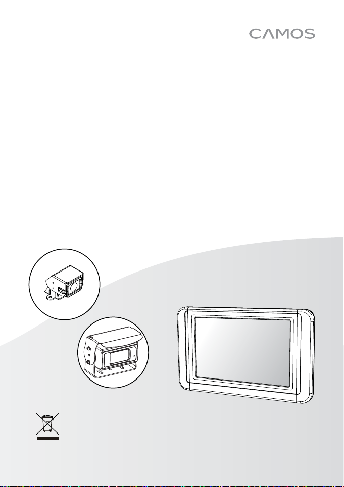
INSTRUCTION MANUAL
Thank you for purchasing this product.
please read this instruction manual thoroughly.
For correct use and application,
SV -420 / SV-430
REAR-VIEW SYSTEM FOR VEHICLE
PRINTED IN KOREA
* Design and speci cations could be changed without notices.
ver. 1.0
Page 2
CONTENTS
REAR-VIEW SYSTEM FOR VEHICLE
SAFEGUARD INSTRUCTIONS
FEATURE
BOX CONTENTS
FUNCTION OF EACH PART
FUNCTIONS
INSTALLATION
CABLE CONNECTION
SPECIFICATIONS
..............................................................................6
................................................................. 6
.............................................. 7
........................................................................ 8
................................................................ 10
.................................................... 12
............................................................. 13
......................................... 4
3
Page 3
SAFEGUARD INSTRUCTIONS
REAR-VIEW SYSTEM FOR VEHICLE
Please pay attention to the warnings and cautions listed in order to prevent the potential risks.
“WARNING” and “CAUTION” symbols are divided according to the different level of risk.
This information is for preventing damage or shorten the life time of
CAUTION
WARNING
CAUTION
Should install while power off. (After install products, connect DC jack)
- It may cause to electronic shock or malfunction.
While stop driving (parking), set the car in motion.
- It may cause battery discharge.
Do not use multi socket or extended adaptor.
- It may cause unexpected heating, fire and malfunction.
Unplug product when do not use for a long time.
- It may case fire by short circuit due to heating.
Do not place near magnet.
- It may cause malfunction and trouble.
the products.
This information is for preventing bodily harm or even death and use
should follow this safety rules.
4
Page 4
WARNING
Do not put the product in place where sudden temperature increasing and should use
on optimum voltage, temperature and humidity.
Do not place near of air bag effective range.
- It may cause malfunction of air bag or accident, injury due to hitting monitor by air bag.
Keep clean dust on power socket.
- It may cause electronic shock and fire by bad connection.
Do not pull cord with a jerk, should catch a plug and pull. Do not use damaged cord.
- It may cause cord malfunction, electronic shock and fire.
Please use dry cloth for exterior cleaning.
- Wet cloth may cause a electronic shock.
Do not clean exterior with volatility or oily solvent.
Neither keep touching rubber and plastic for long time.
- It may cause change of surface, fall of paint, malfunction and fire.
Do not place where vibration and shock.
- It may cause throw down and then malfunction and accident.
Do not put metals as like pin and needle into hole and chink of grill, speaker.
- In case of inser ting them, stop to operate, it may cause electronic shock, fire and
malfunction.
Do not use in problem condition as like smoking, smell something burn.
- It may cause fire. Stop to use and make inquiries to agency.
Do not disassemble, repair and remodeling.
- It may cause malfunction and injury, can not get warranty.
- Make inquiries to agent for repair and checkup.
When the power cable cord touches a metal case, cover it with a friction tape.
- Short circuit or disconnection of wire may cause a fire or accident.
Do not use bolts or nuts from a parts for vehicle.
- Using bolt or nuts from steering column or break may cause an accident.
After installing, check it break lamp, head lamp and wipe works properly.
5
Page 5
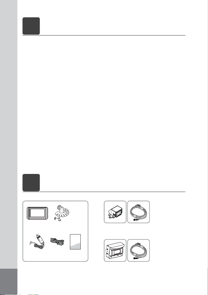
FEATURE
1
REAR-VIEW SYSTEM FOR VEHICLE
[ CM-430 MONITOR ]
• Adopting high resolution LCD panel
• All functions are displayed on screen (OSD function)
• 5 languages display selection (ENG-DEU-ITA-FRA-ESP)
[ CM-200 CAMERA ] [ CM-36 CAMERA ]
• 1/3” 960H color CCD
• 5 pcs of IR LEDs for night
• Waterproof (IP67)
• Audio Built-in
• Heating function Built-in
• Die-casting housing
• Photo sensor
BOX CONTENTS
2
REAR-VIEW SYSTEM FOR VEHICLE
[Monitor]
• 1/3” 960H color CCD
• 6 pcs of IR LEDs for night.
• Waterproof (IP-67)
• Audio Built-in
• Heating function Built-in
• Aluminum die-casting housing
• Photo sensor
[SV-420]
CM-430 CL-5S
Cigar Cable ManualTrigerline
* Design and specifications are subject to change without notice.
6
+
+
CM-200
[SV-430]
CM-36
Extension Cable
(for camera)
Extension Cable
(for camera)
Page 6
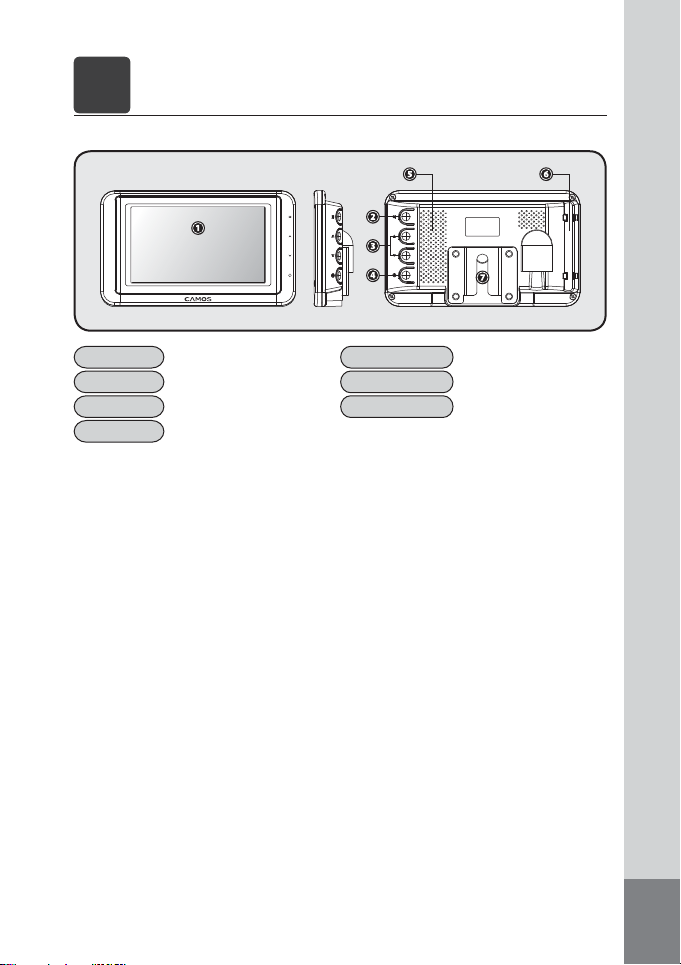
FUNCTION OF EACH PART
3
REAR-VIEW SYSTEM FOR VEHICLE
[ CM-430 MONITOR ]
4.3” TFT LCD (480x272)
1. Display
2. MENU
3. Volume
4. Power
-
Menu setting and change
Volume setting
Power ON/OFF
5. Speaker
6. Cable Guidance
7. Bracket
Max. 0.5W(MONO)
-
Stand Bracket connect part
7
Page 7
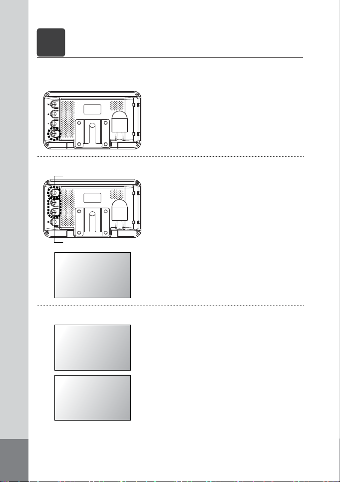
FUNCTIONS
4
REAR-VIEW SYSTEM FOR VEHICLE
[ CM-430 MONITOR ]
1. Power ON/OFF
2. Button function
MENU button
Volume / Setting changes
VOLUME 50
3. MENU function
BRIGHTNESS 70
1) POWER ON : If you push, POWER ON. (STAND BY state is OFF)
2) POWER OFF : If you push again, POWER OFF.
The menu changes [BRIGHTNESS] - [CONTRAST] - [COLOR] [TINT] - [DIMMER] - [LANGUAGE] - [MONITOR] - [RESET] ever y
push [MENU] button.
·[VOLUME] : Volume control
When you push△▽ button, it controls volume normally. (0~100)
[0 : Min. volume / 100 : Max. volume]
·[BRIGHTNESS] : Adjust Brightness
On Brightness setting mode, △▽ buttons control screen
brightness. (0~100)
[0 : Dark / 100 : bright]
·[CONTRAST] : Adjust Contrast
On Contrast setting mode, △▽ buttons control the difference
between brightness and darkness on screen. (0~100)
CONTRAST 70
[0 : Min. difference between brightness/darkness
100 : Max. difference between brightness / darkness]
8
Page 8
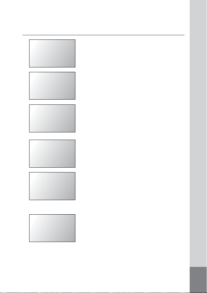
COLOR 50
TINT 50
DIMMER DAY
LANGUAGE ENGLISH
MONITOR AUTO
RESET ►
·[COLOR] : Density adjusting on screen color
On Color setting mode, △▽ buttons control density of screen
color. (0~100)
[0 : Low density / 100 : High density]
·[TINT] : Screen color adjusting
On Tint setting mode △▽ buttons control screen color. (0~100)
·[DIMMER] : Automatic brightness adjusting
On Dimmer setting mode, the menu changes [DAY] - [NIGHT]
every pushing △▽ buttons.
• DAY : Making bright screen conpulsorily.
• NIGHT : Making dark screen compulsorily.
·[LANGUAGE] : OSD language choice
On language setting mode, △▽ buttons change OSD language
(5 languages)
[ENG]-[DEU]-[ITA]-[FRA]-[ESP]
·[MONITOR] : Screen ON/OFF setting
On Monitor setting mode, △▽ buttons change [AUTO] [Manual] mode.
• AUTO : When you put into reverse gear, the screen shows
reverse image through camera. (Normally blackscreen)
• MANUAL : Always screen on.
·[RESET] : Reset (Factory mode)
On Reset setting mode, when you push △ button, it turns to
initial setting mode.
9
Page 9
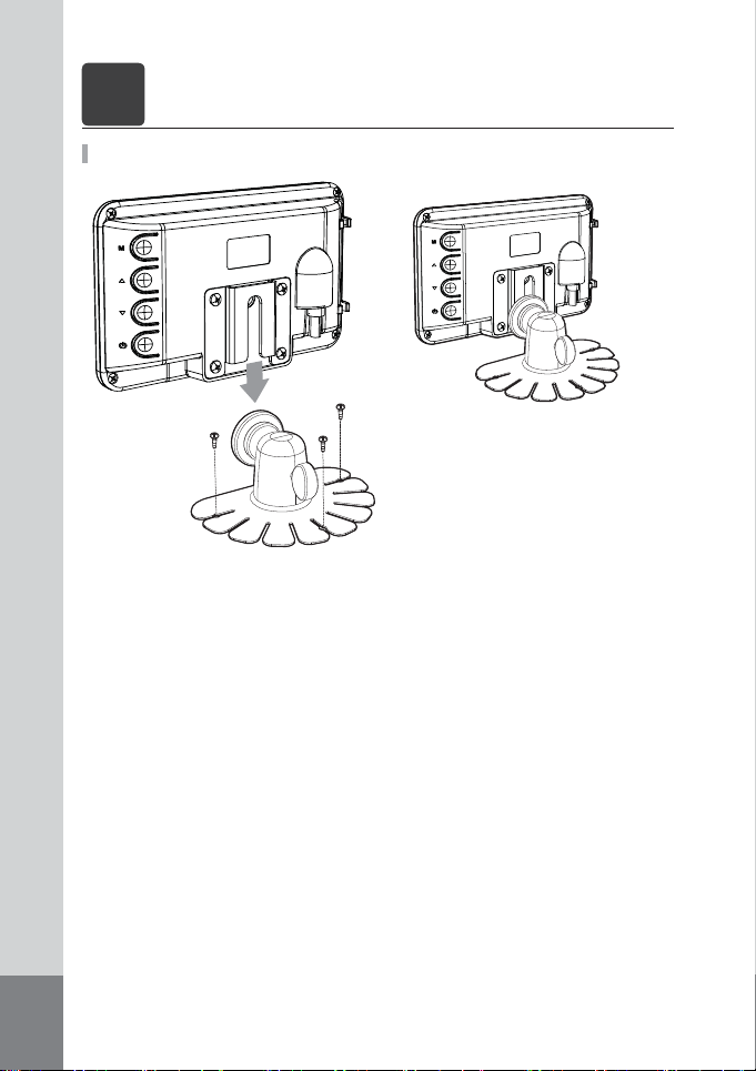
INSTALLATION
5
REAR-VIEW SYSTEM FOR VEHICLE
MONITOR INSTALLATION
1. Remove protecting tape from below of stand and attach stand with double stick tape.
2. Fix a stand with enclosed 3 screws.
3. Connect stand and monitor.
10
Page 10
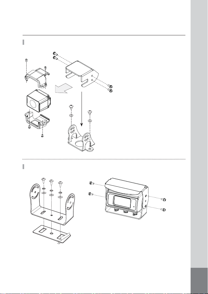
SV-420 CAMERA INSTALLATION (CM-200)
2
5
5
2
3
1
2
2
6
6
4
SV-430 CAMERA INSTALLATION (CM-36)
1. Determine a position and direction of installation and
attach a camera bracket using double stick tape and
screws.
2. Connect a camera with bracket on vehicle and fix them
with screws. After that fix a sun visor with screws.
3. Run the cable as following cable connection guide.
5
5
1. Determine a position and direction of installation and attach a camera bracket using
double stick tape and screws.
2. Connect a camera and sun visor with
bracket on vehicle and fix them with screws.
3. Run the cable as following cable connection
guide.
11
Page 11
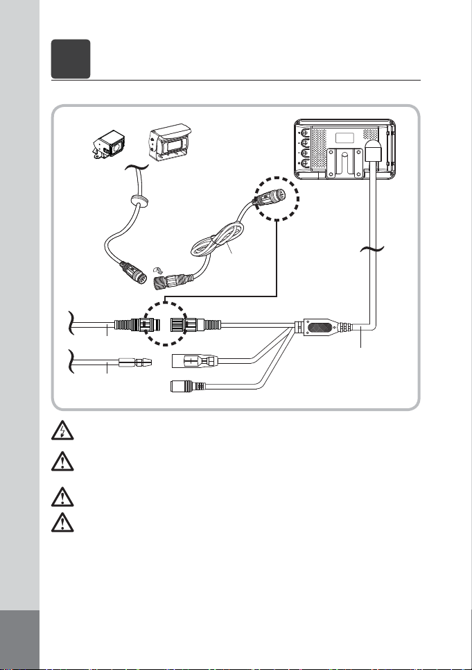
CABLE CONNECTION
6
REAR-VIEW SYSTEM FOR VEHICLE
[ CM-430 MONITOR ]
CM-36CM-200
OR
Extension Cable
(for Camera)
CAMERA
Extension Cable
(for CAMERA)
Extension Cable
(for TRG)
Before making the connection, disconnect the ground terminal of the car battery to
avoid short circuiting.
The plug should be fully inserted into the connector, should be check pin arrangement
before inserting. A loose connection may be caused mallfunction or problem of the
unit.
When use extension cable, connect it as follows arrow direction.
After complete the cable connection, test them as below whether it is connected well
or not.
TRG
DC IN (12V~24V)
Monitor Cable
12
Page 12
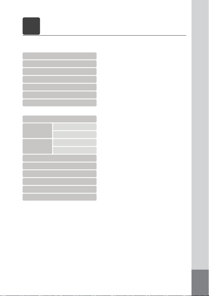
SPECIFICATION
7
REAR-VIEW SYSTEM FOR VEHICLE
CM-430 (MONITOR)
<LCD Panel>
LCD size
Image ratio
Resolution
Brightness
Contrast range
Active area
Viewing angle
<Monitor>
Input System
Input
Power
Operating temperature
Operating voltage
Current consumption
Speaker
OSD Display language
Storage temperature
Dimension
Weight
Video signal
Audio signal
4.3”
16 : 9
480 x 3(RGB) x 272
400cd
600 : 1
95.04(W ) x 53.86(H) mm
80(L) / 80(R) / 65(T ) / 52(B)
NTSC/PAL
Composite Video (CVBS) 75Ω 1Vp-p
MONO
DC 12V - 24V
200mA
Max. 0.5W
5 Languages
-30˚C ~ 70˚C
-40˚C ~ 80˚C
140(W ) x 83(H) x 20(D) mm
about. 238.5g (monitor only)
13
Page 13
CM-200 (CAMERA)
Image sensor
Viewing angle
Min. Illumination
Resolution
Operating voltage
Operating temperature
Dimension
Weight
CM-36 (CAMERA)
Image sensor
Viewing angle
Min. Illumination
Resolution
Operating voltage
Operating temperature
Dimension
Weight
1/3” 960H color CCD
168(D) / 125(H)
0.1Lux (F=2.0)
700 TV Lines
DC12V / 90mA
-30°C ~ 70°C
36.6(W ) x 27(H) x 38.2(D) mm
80g (Body only)
1/3” 960H color CCD
120(D) / 95(H)
0.1Lux (F=2.0)
700 TV Lines
DC12V / 110mA
-30°C ~ 70°C
89(W ) x 57.2(H) x 60.5(D) mm
266g (Body only)
14
Page 14
MEMO
REAR-VIEW SYSTEM FOR VEHICLE
15
Page 15

INSTRUCTION MANUAL
INSTRUCTION MANUAL
 Loading...