

Page 1
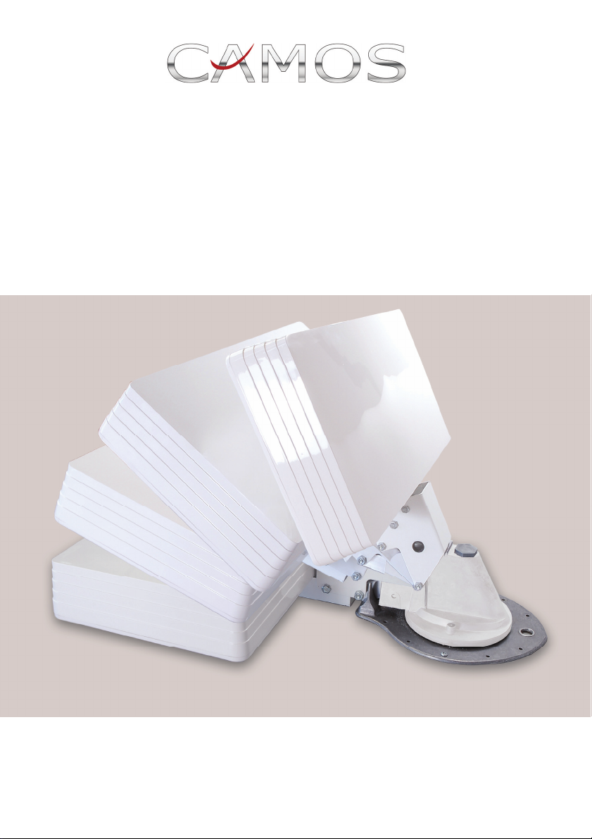
Selfsat TOP
Dach-Flachantenne mit kompakter Dreheinheit
Zusatz
Montage- und Bedienungsanleitung
www.camos-multimedia.com
Page 2
1. Inhalt der Verpackung:
Anzahl Beschreibung
1 Antenne Selfsat HD 10 mit Halterung
1 Dreheinheit (vormontiert)
2 Stabilisierungsplatten (1Haupt- und 1 Zusatzplatte)
1 Grundplatte
1 Handrad
1 Kurbel
1 Feder
1 Gleitring
1 Skalenscheibe
1 Antennenkabel 5m einseitig mit F-Stecker
1 F-Stecker
1 Gel-Kappe
1 Dachdurchführung
Kompass
Schrauben
2. Benötigtes Werkzeug und Material (nicht im Lieferumfang)
Bohrmaschine / Bohrschrauber
Bohrer 1,5mm
Bohrer 13mm
Lochsäge 38 mm
Kreuzschraubendreher
Schlitzschraubendreher
Körner
Bandmaß
Cuttermesser
Klebeband
Sikaflex Dichtungskleber
Markierungsstift
Page 3

3. Vorbereitung der Installation
Suchen Sie eine geeignete Stelle auf dem Fahrzeugdach aus.
Idealerweise sollte die Antenne in alle Richtungen frei drehbar sein, und
in keiner Position durch andere Dachaufbauten abgeschattet werden.
Achten Sie darauf, dass diese Stelle auch im Innenraum frei zugänglich
ist und keine Lampen, Kabel oder Einbauten beim Durchbohren des
Daches beschädigt werden.
Markieren Sie die Position der Dreheinheit, indem Sie die in dieser
Anleitung enthaltene Schablone
1)
mit Klebeband fixieren.
Die Antenne muss hierbei in Fahrtrichtung hinter der Dreheinheit
liegen. Markieren Sie nun das Mittelloch mit einem Körner.
Das Loch für die Durchführung des Antennenkabels sollte ca. 10-13cm
vor der Dreheinheit, ebenfalls in Fahrtrichtung, mit dem Körner markiert
werden.
Abb.1
Fahrtrichtung
Kabeldurchführung
Dachdurchführung
10-13cm
Achten Sie auch hier darauf, dass diese Stelle auch im Innenraum frei
zugänglich ist und keine Lampen, Kabel oder Einbauten beim
Durchbohren des Daches beschädigt werden.
1)
auf beiliegendem DIN A4 Bogen
Page 4
A
4. Montage der Dreheinheit
Schneiden Sie mit der Lochsäge ein Loch von 38mm in das Dach.
Tragen Sie auf der Unterseite der Dreheinheit jeweils um den
Mittelzapfen herum und entlang der Außenkante der Dreheinheit einen
ca. 0,5 cm dicken Strang Sikaflex®. Befolgen Sie dabei die
Anweisungen des Herstellers mit Hinsicht auf die Vorbereitung der
Oberfläche, das Auftragen und das Aushärten.
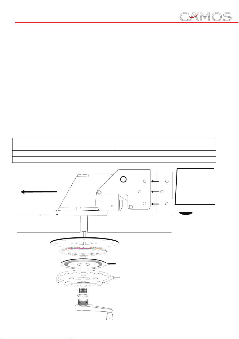
Stecken Sie jetzt den Mittelzapfen mit dem Vierkant durch das Loch und
richten die Dreheinheit mit dem Getriebe in Fahrtrichtung aus.
Verschrauben Sie die Dreheinheit rundherum mit den beigelegten
selbstschneidenden Blechschrauben (Hinweis: Hierfür ist nur ein sehr
geringes Drehmoment notwendig).
Montieren Sie nun im Inneren des Fahrzeuges die Bedieneinheit.
Je nach Dachstärke benötigen Sie hierzu eine oder zwei
Stabilisierungsplatten.
Dachstärke
bis 32mm 2 Platten
ab 32 mm 1 Platte
ab 50 mm keine Platte
Fahrtrichtung
Dreheinheit (vormontiert)
nzahl Stabilisierungsplatten
Antenne
Stabilisierungsplatte
Skalenscheibe
Grundplatte
Handrad
Feder
Gleitring
Kurbel
Page 5
Befestigen Sie nun die Antenne mit vormontierter Halterung an der
Dreheinheit mittels der 3 beigefügten Schrauben mit Muttern
(M5x62mm).
5. Anschließen der Antenne
Schließen Sie das Kabel mit dem F-Stecker an die Antenne an. Führen
Sie das Kabel durch die seitliche Öffnung in der Dreheinheit, dann
durch die hintere Öffnung der Dachdurchführung (s.Abb.1). Die Länge
des Antennenkabels zwischen Dachdurchführung und Antenne sollte
ca. 70cm (siehe Markierung) betragen. Nachdem Sie das Kabel durch
die Bohrung ins Fahrzeuginnere geführt haben, kleben Sie die
Dachdurchführung auf das Fahrzeugdach (z.B. mit Sikaflex®).
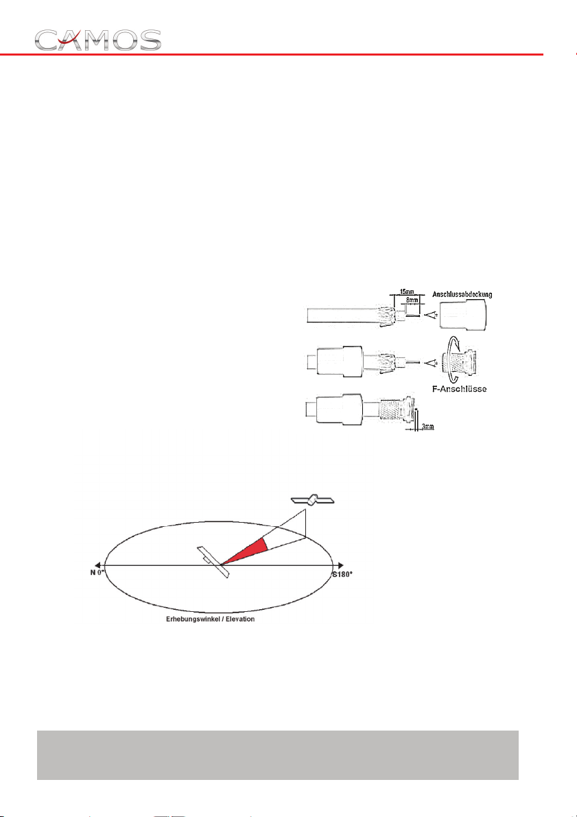
Montieren Sie am receiverseitigen
Kabelende einen F-Stecker und
verbinden Sie diesen mit der
entsprechenden Buchse Ihres
Receivers.
6. Ausrichten der Antenne:
Stellen Sie zunächst anhand der Tabelle in Ihrem Antennenhandbuch
fest, welcher Elevationsgrad der Antenne für ihren Standort vorgegeben
ist.
Drehen Sie nun die Kurbel so oft im Uhrzeigersinn wie für die nötige
Elevation erforderlich.
Die Anzahl der Umdrehungen können Sie den Angaben auf der
Skalenscheibe an der Dreheinheit entnehmen.
Achtung: Die Angaben stellen ungefähre Werte dar, die je nach
Standort geringfügig variieren können.
Page 6
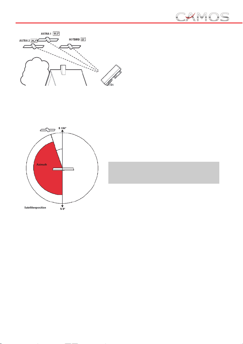
Ebenfalls auf der Scheibe finden Sie die
Position der einzelnen Satelliten.
Ermitteln Sie mit Hilfe des beigelegten
Kompasses Norden.
Drehen Sie die Skalenscheibe mit der Kennzeichnung N nach Norden.
Das Handrad wird nun mit der Zeigerspitze in den Bereich des
gewünschten Satelliten gedreht.
Drehen Sie das Handrad innerhalb
des markierten Bereiches langsam
weiter, bis Sie Ihr gewünschtes
Fernsehprogramm empfangen.
Achtung: Versuchen Sie auf keinen
Fall, die Antenne über einen
Widerstand hinauszudrehen.
Bei den meisten Satellitenreceivern können Sie an der Bildunterkante
die durch einen farbigen Balken dargestellte Signalqualität ablesen.
Diese Anzeige erlaubt es Ihnen eine Feineinstellung Ihrer Antenne
vorzunehmen.
Bewegen Sie hierzu das Handrad langsam nach links und rechts und
beobachten Sie den Signalbalken auf Ihrem Monitor.
Der Punkt des höchsten Ausschlages ist die beste Position.
Ebenso können Sie mit der Kurbel durch drehen im- oder drehen gegen
den Uhrzeigersinn die beste Signalqualität einstellen.
Page 7

7. Umlegen der Antenne:
Drehen Sie die Antenne mit dem Handrad so, dass die Zeigerspitze der
Grundplatte mit der Zeigerspitze des Handrades übereinstimmen.
Sollten Sie während der Drehung des Handrades einen Widerstand
spüren, drehen Sie bitte in die entgegengesetzte Richtung, um das
äußere Antennenkabel nicht zu beschädigen.
Erst wenn beide Zeigerspitzen übereinander stehen darf die Antenne
mit der Handkurbel in die Ruheposition gebracht werden.
Achtung: Das Fahren mit aufgerichteter oder nur teilweise
umgelegter Antenne kann zu Schäden an der Getriebemechanik führen.
Technische Daten:
Modelname Camos SelfSat Top
Eingangsfrequenz 10.7 - 12.75 GHz
Polarisation Dual Linear ( Horizontal und vertikal )
Antennenempfangsleistung 33 dBi bei 12.75 GHz
LNB 1
LNB Ausgangsfrequenz 950 - 1950 / 1100 - 2150 MHz
L.O. Frequenz 9.75 / 10.6 GHz
Betriebstemperatur - 30 Grad bis +60 Grad
Lagerungstemperatur - 40 Grad bis +80 Grad
Maße:
Antenne (BxHxT in cm): 47,5 x 25,9 x 7
Dreheinheit inkl. Antenne: 5,5 kg
Page 8

Page 9
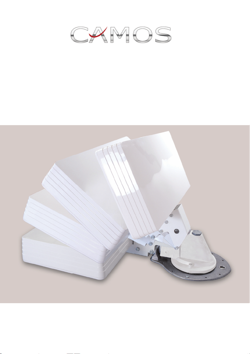
Selfsat TOP
Satellite Flat Antenna with Lift and Rotation Unit
Manual
Page 10
www.camos-multimedia.com
5. Contents:
Quantity Description
1 Antenna Selfsat HD 10
1 Lift and Rotation Unit (pre-assembled)
2 Ceiling Support plates
1 Ceiling plate
1 Rotation handle
1 Elevation handle
1 Spring
1 Washer
1 Graduation disc
1 Antenna cable 5m one side with F-series connector
1 F-connector
1 Protector Gel
1 Cable entry box
Screws
6. Tools required:
Electric Drill
Drill bits: 1,5mm and 13mm
Hole saw 38 mm diameter
Crosstip screwdriver
Slotted screwdriver
Centre punch
Measuring tape
Cutter
Adhesive tape
Adhesive such as Sikaflex
Marker
Page 11
7. Installation Planning
Decide where you wish to mount your satellite system.
Location of the lift assembly must allow antenna to point towards the
rear of the vehicle when resting in the travel position, and must clear all
roof mounted equipment when being raised, lowered or rotated.
The inside ceiling must be clear of obstructions to ceiling plate and
handle. Before drilling, check for cables or obstructions within the roof
space.
Tape the drill template to the roof of the vehicle in the position where
the lift assembly will be installed. Mark the centre hole as well as
mounting holes. Ensure that the lift assembly is located in front of
the antenna pointing in direction of motion.
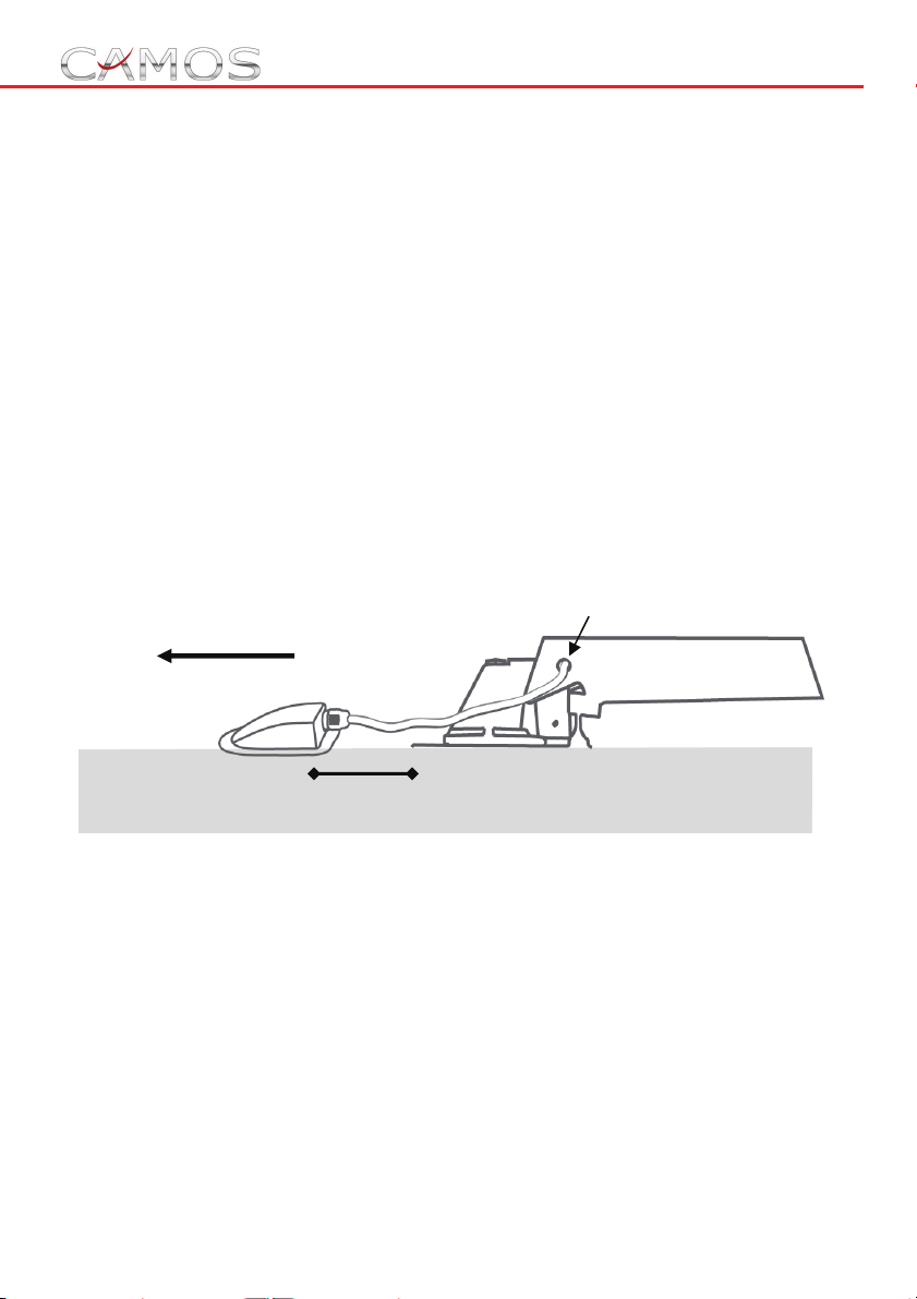
The roof perforation for antenna cable should be located approx. 13 cm
in front of lift assembly (in direction of motion).
Direction of motion
cable feedthrough
Cable entry box
10-13cm
Also, check for cables, equipment, or obstructions inside the vehicle
before drilling.
Select the location and drill one 13 mm diameter hole through the roof
only for the coaxial cable.
Page 12
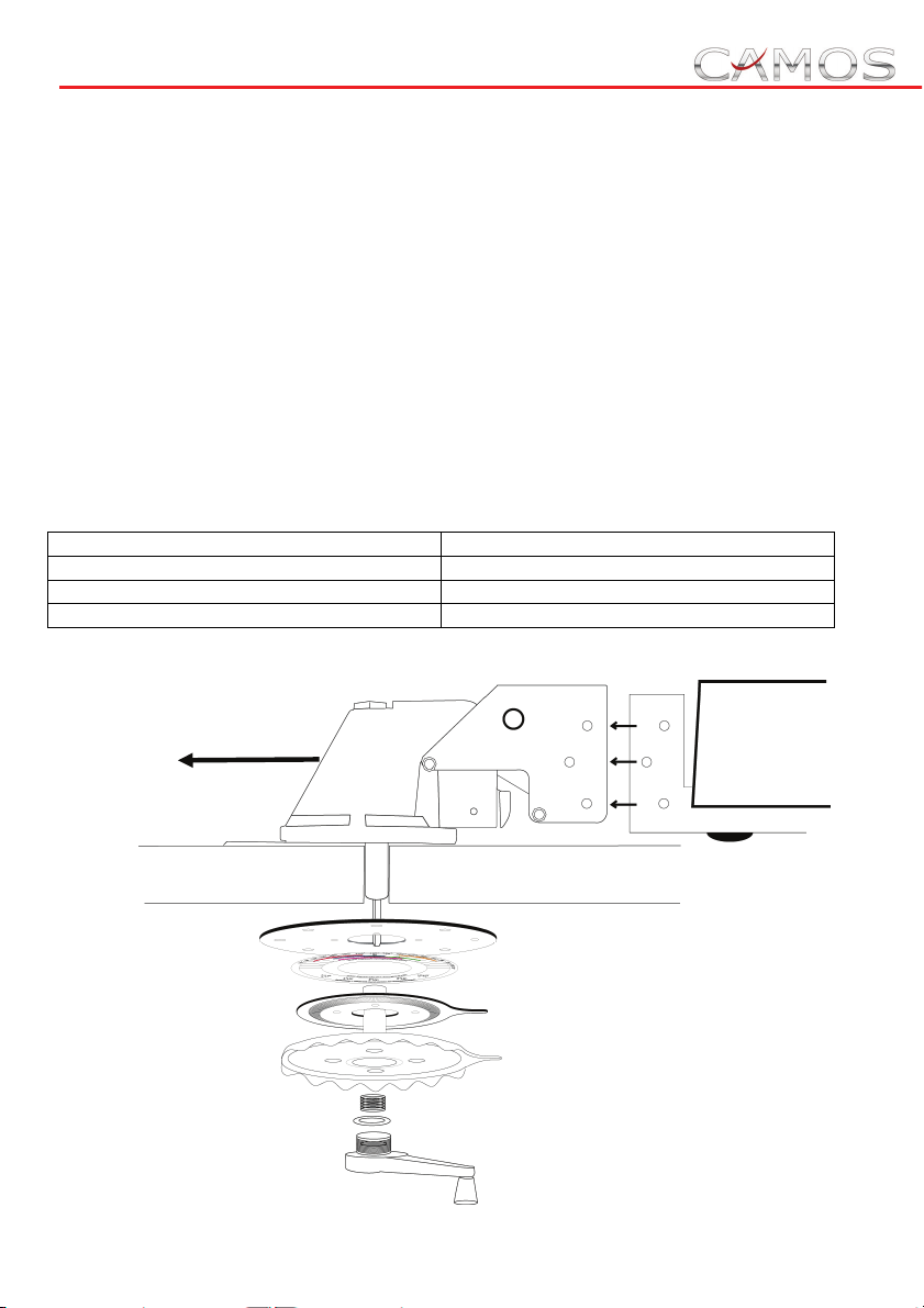
8. Mounting
Using a 38mm diameter hole saw, cut a hole through the roof and
ceiling for the centre shaft. Apply a
adhesive such as
Sikaflex® on the bottom of the base plate. Follow the
layer of approx. 0,5 cm thick of
manufacturer’s guidelines for surface preparation, application and
curing.
Insert the crankshaft with square tube into the hole, then position and
attach the lift assembly to the roof with the enclosed
screw
s.
self-cutting tapping
Measure the thickness of the roof. Using the table below, decide if you
need one or two ceiling support plates. Assemble graduation disc,
ceiling plate, rotation handle, spring, washer and elevating handle (See
illustration). Slide all parts over shaft and tighten the screw in the
elevation handle.
Roof thickness Number of ceiling support plates
Up to 32mm 2
From 32 mm 1
From 50 mm None
Direction of motion
Antenna
Lift assembly
Ceiling support plate
Graduation disc
Ceiling plate
Rotation handle
Spring
Washer
Elevation handle
Page 13
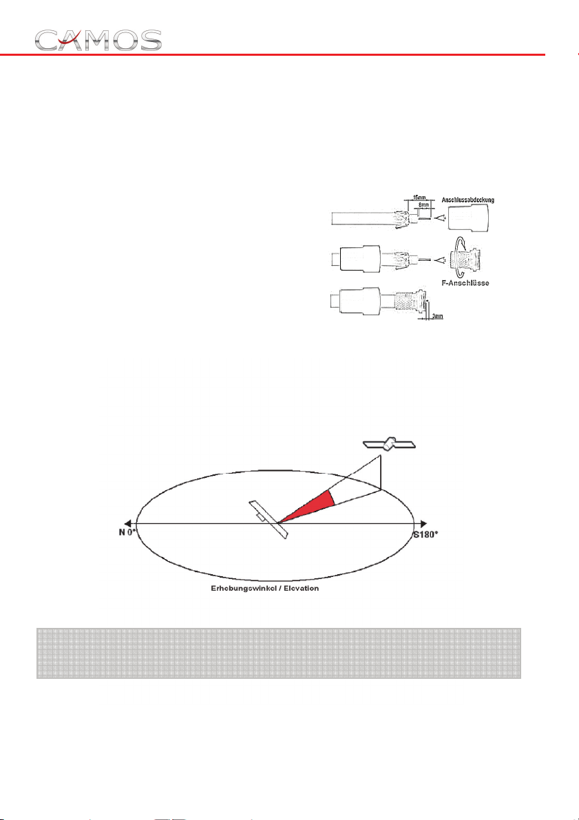
5. Connecting the Antenna
Connect the coaxial cable to the antenna and tighten. Feed the cable
sidewise through the lift assembly, then insert cable through gland in
rear of roof entry box and push cable into vehicle. Leave 70 cm of cable
(see indication) from antenna to roof entry. Following glue on the cable
entry box to the roof (e.g. with Sikaflex®).
Route cable to satellite receiver
and fit ‘F’ connector.
Connect to the connector marked
"SATELLITE IN" on the rear of the
satellite receiver.
6. To locate the satellite:
Using the zone map determine your location and note the angle of
elevation required. Turn the elevation handle counter clockwise (ccw)
the number of turns indicated in the graduation disc to get the elevation
for your location.
Note: The specifications are approximate values, depending on
the location.
Page 14
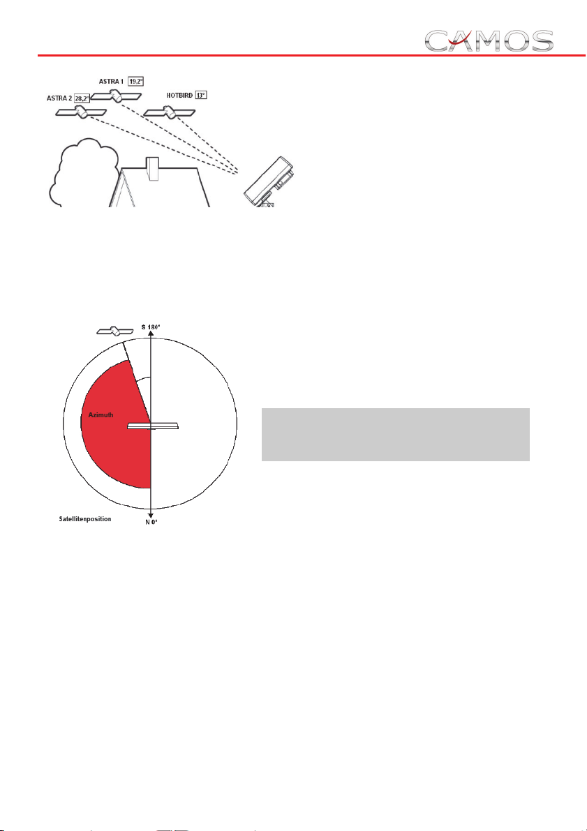
The graduation disc also will be used to
indicate the approximate direction and
position of the desired satellite. With the
enclosed compass find out the
direction north and turn the
Indicator "N" into this
direction.
Turn the indicator of rotation handle into the area of desired satellite,
which
appears highlighted in colour on the graduation disc.
Turn the rotation handle slowly inside
this area, until you receive the desired
TV-channel.
Note: Stop rotating the antenna if
you notice a resistance. Don't try to
get over it.
Note: Most receivers display the signal strength on the TV set. You can
use this option to maximize the signal strength by sweeping the dish
from side to side.
For fine tuning you may turn the rotation handle slowly to the left or
right. Also, use the elevation handle and turn it marginally clockwise or
counter clockwise to get the best signal.
Page 15

7. To Lower Antenna:
Pull rotation handle down to disengage gear from ceiling plate and
rotate the antenna until the pointer on the ceiling plate is aligned with
the pointer on the rotation handle. Rotate elevation handle counter
clockwise until you hear the antenna touch the roof (resistance will be
felt in the handle).
If you notice resistance during rotation (the antenna cable maybe
winded around the unit), turn into contrary direction.
WARNING ! ! ! Vehicle must not be driven with antenna in raised
or partially raised position. Align the pointers on the ceiling plate
and rotation handle before you lower the Antenna.
Technical Details:
Model: Camos SelfSat Top
Frequency range : 10.7 - 12.75 GHz
Polarisation Dual Linear ( horizontal and vertical )
Gain 33 dBi bei 12.75 GHz
LNB 1
LNB Output frequency 950 - 1950 / 1100 - 2150 MHz
L.O. Frequency 9.75 / 10.6 GHz
Operating temperature - 30 Grad bis +60 Grad
Storage temperature - 40 Grad bis +80 Grad
Dimension:
Antenna (LxHxD in cm): 47,5 x 25,9 x 7
Weight: 5,5 kg
Page 16

IMC GmbH (Camos Europe)
Carl-Zeiss-Str. 7
22946 Trittau
Tel 04154 / 8083 - 0
www.camos-multimedia.com
[email protected]
 Loading...