

Cameo Communications WLG2211 User Manual

TM
108Mbps Super-G
Wireless LAN Router
CAMEO / WLG-2211
User’s Manual

Federal Communication Commission Interference Statement
This equipment has been tested and found to comply with the limits for a Class B digital device, pursuant to Part 15 of the FCC Rules.
These limits are designed to provide reasonable protection against harmful interference in a residential installation. This equipment
generates, uses and can radiate radio frequency energy and, if not installed and used in accordance with the instructions, may cause
harmful interference to radio communications. However, there is no guarantee that interference will not occur in a particular
installation. If this equipment does cause harmful interference to radio or television reception, which can be determined by turning
the equipment off and on, the user is encouraged to try to correct the interference by one of the following measures:
- Reorient or relocate the receiving antenna.
- Increase the separation between the equipment and receiver.
- Connect the equipment into an outlet on a circuit different from that
to which the receiver is connected.
- Consult the dealer or an experienced radio/TV technician for help.
FCC Caution: Any changes or modifications not expressly approved by the party responsible for compliance could void the user's
authority to operate this equipment.
This device complies with Part 15 of the FCC Rules. Operation is subject to the following two conditions: (1) This device may not
cause harmful interference, and (2) this device must accept any interference received, including interference that may cause undesired
operation.
IMPORTANT NOTE:
Radiation Exposure Statement:
This equipment complies with FCC radiation exposure limits set forth for an uncontrolled environment. This equipment should be
installed and operated with minimum distance 20cm between the radiator & your body.
This transmitter must not be co-located or operating in conjunction with any other antenna or transmitter.
The availability of some specific channels and/or operational frequency bands are country dependent and are firmware programmed at
the factory to match the intended destination. The firmware setting is not accessible by the end user.
Europe – EU Declaration of Conformity
This device complies with the essential requirements of the R&TTE Directive 1999/5/EC. The following test methods have been
applied in order to prove presumption of conformity with the essential requirements of the R&TTE Directive 1999/5/EC:
EN 60 950-1: 2001 +A11: 2004
Safety of Information Technology Equipment
EN50385 : (2002-08)
Product standard to demonstrate the compliance of radio base stations and fixed terminal stations for wireless telecommunication
systems with the basic restrictions or the reference levels related to human exposure to radio frequency electromagnetic fields
(110MHz - 40 GHz) - General public
EN 300 328 V1.7.1: (2006-10)
Electromagnetic compatibility and Radio spectrum Matters (ERM); Wideband Transmission systems; Data transmission equipment
operating in the 2,4 GHz ISM band and using spread spectrum modulation techniques; Harmonized EN covering essential
requirements under article 3.2 of the R&TTE Directive
EN 301 489-1 V1.6.1: (2005-09)
Electromagnetic compatibility and Radio Spectrum Matters (ERM); ElectroMagnetic Compatibility (EMC) standard for radio
equipment and services; Part 1: Common technical requirements
EN 301 489-17 V1.2.1 (2002-08)
i

Electromagnetic compatibility and Radio spectrum Matters (ERM); ElectroMagnetic Compatibility (EMC) standard for radio
equipment and services; Part 17: Specific conditions for 2,4 GHz wideband transmission systems and 5 GHz high performance RLAN
equipment
This device is a 2.4 GHz wideband transmission system (transceiver), intended for use in all EU member states and EFTA countries,
except in France and Italy where restrictive use applies.
In Italy the end-user should apply for a license at the national spectrum authorities in order to obtain authorization to use the device
for setting up outdoor radio links and/or for supplying public access to telecommunications and/or network services.
This device may not be used for setting up outdoor radio links in France and in some areas the RF output power may be limited to 10
mW EIRP in the frequency range of 2454 – 2483.5 MHz. For detailed information the end-user should contact the national spectrum
authority in France.
[Czech]
[Danish]
[German]
[Estonian]
[Spanish]
[Greek]
Deutsch
English
Español
Ελληνική
0560
Česky
Dansk
Eesti
[Jméno výrobce] tímto prohlašuje, že tento [typ zařízení] je ve shodě se základními požadavky a dalšími
příslušnými ustanoveními směrnice 1999/5/ES.
Undertegnede [fabrikantens navn] erklærer herved, at følgende udstyr [udstyrets typebetegnelse]
overholder de væsentlige krav og øvrige relevante krav i direktiv 1999/5/EF.
Hiermit erklärt [Name des Herstellers], dass sich das Gerät [Gerätetyp] in Übereinstimmung mit den
grundlegenden Anforderungen und den übrigen einschlägigen Bestimmungen der Richtlinie 1999/5/EG
befindet.
Käesolevaga kinnitab [tootja nimi = name of manufacturer] seadme [seadme tüüp = type of equipment]
vastavust direktiivi 1999/5/EÜ põhinõuetele ja nimetatud direktiivist tulenevatele teistele asjakohastele
sätetele.
Hereby, [name of manufacturer], declares that this [type of equipment] is in compliance with the essential
requirements and other relevant provisions of Directive 1999/5/EC.
Por medio de la presente [nombre del fabricante] declara que el [clase de equipo] cumple con los
requisitos esenciales y cualesquiera otras disposiciones aplicables o exigibles de la Directiva 1999/5/CE.
ΜΕ ΤΗΝ ΠΑΡΟΥΣΑ [name of manufacturer] ∆ΗΛΩΝΕΙ ΟΤΙ [type of equipment] ΣΥΜΜΟΡΦΩΝΕΤΑΙ
ΠΡΟΣ ΤΙΣ ΟΥΣΙΩ∆ΕΙΣ ΑΠΑΙΤΗΣΕΙΣ ΚΑΙ ΤΙΣ ΛΟΙΠΕΣ ΣΧΕΤΙΚΕΣ ∆ΙΑΤΑΞΕΙΣ ΤΗΣ Ο∆ΗΓΙΑΣ
1999/5/ΕΚ.
Français
[French]
Italiano
[Italian]
Latviski
[Latvian]
Lietuvių
[Lithuanian]
Nederlands
[Dutch]
Malti
[Maltese]
Par la présente [nom du fabricant] déclare que l'appareil [type d'appareil] est conforme aux exigences
essentielles et aux autres dispositions pertinentes de la directive 1999/5/CE.
Con la presente [nome del costruttore] dichiara che questo [tipo di apparecchio] è conforme ai requisiti
essenziali ed alle altre disposizioni pertinenti stabilite dalla direttiva 1999/5/CE.
Ar šo [name of manufacturer / izgatavotāja nosaukums] deklarē, ka [type of equipment / iekārtas tips]
atbilst Direktīvas 1999/5/EK būtiskajām prasībām un citiem ar to saistītajiem noteikumiem.
Šiuo [manufacturer name] deklaruoja, kad šis [equipment type] atitinka esminius reikalavimus ir kitas
1999/5/EB Direktyvos nuostatas.
Hierbij verklaart [naam van de fabrikant] dat het toestel [type van toestel] in overeenstemming is met de
essentiële eisen en de andere relevante bepalingen van richtlijn 1999/5/EG.
Hawnhekk, [isem tal-manifattur], jiddikjara li dan [il-mudel tal-prodott] jikkonforma mal-ħtiġijiet
essenzjali u ma provvedimenti oħrajn relevanti li hemm fid-Dirrettiva 1999/5/EC.
ii

Magyar
[Hungarian]
Alulírott, [gyártó neve] nyilatkozom, hogy a [... típus] megfelel a vonatkozó alapvetõ követelményeknek
és az 1999/5/EC irányelv egyéb elõírásainak.
Polski
[Polish]
Português
[Portuguese]
Slovensko
[Slovenian]
Slovensky
[Slovak]
Suomi
[Finnish]
Svenska
[Swedish]
Niniejszym [nazwa producenta] oświadcza, że [nazwa wyrobu] jest zgodny z zasadniczymi wymogami
oraz pozostałymi stosownymi postanowieniami Dyrektywy 1999/5/EC.
[Nome do fabricante] declara que este [tipo de equipamento] está conforme com os requisitos essenciais e
outras disposições da Directiva 1999/5/CE.
[Ime proizvajalca] izjavlja, da je ta [tip opreme] v skladu z bistvenimi zahtevami in ostalimi relevantnimi
določili direktive 1999/5/ES.
[Meno výrobcu] týmto vyhlasuje, že [typ zariadenia] spĺňa základné požiadavky a všetky príslušné
ustanovenia Smernice 1999/5/ES.
[Valmistaja = manufacturer] vakuuttaa täten että [type of equipment = laitteen tyyppimerkintä] tyyppinen
laite on direktiivin 1999/5/EY oleellisten vaatimusten ja sitä koskevien direktiivin muiden ehtojen
mukainen.
Härmed intygar [företag] att denna [utrustningstyp] står I överensstämmelse med de väsentliga
egenskapskrav och övriga relevanta bestämmelser som framgår av direktiv 1999/5/EG.
iii

TABLE OF CONTENT
A
BOUT THIS GUIDE
Purpose.................................................................................................................................................................................................. 1
Terms/Usage ......................................................................................................................................................................................... 1
Overview of this User’s Guide.............................................................................................................................................................. 1
I
NTRODUCTION
Applications:......................................................................................................................................................................................... 2
Features:................................................................................................................................................................................................ 3
U
NPACKING AND SETUP
Unpacking............................................................................................................................................................................................. 4
Setup ..................................................................................................................................................................................................... 4
H
ARDWARE INSTALLATION
Front Panel............................................................................................................................................................................................ 5
Rear Panel............................................................................................................................................................................................. 6
Hardware connections........................................................................................................................................................................... 7
Connecting the WLAN Router ......................................................................................................................................................... 7
Check the installation........................................................................................................................................................................ 7
...........................................................................................2
....................................................................................1
.............................................................................4
........................................................................5
PC N
C
ETWORK
Windows 95/98/ME.............................................................................................................................................................................. 8
Windows 2000 ...................................................................................................................................................................................... 9
Windows XP....................................................................................................................................................................................... 10
ONFIGURATION
Login to the WLAN Router through Wireless LAN........................................................................................................................... 11
Login to the WLAN Router ................................................................................................................................................................ 11
Using the Web Browser ...................................................................................................................................................................... 11
Setup Wizard....................................................................................................................................................................................... 12
Advanced configuration...................................................................................................................................................................... 21
LAN Setting........................................................................................................................................................................................ 21
LAN & DHCP Server ..................................................................................................................................................................... 21
WAN............................................................................................................................................................................................... 22
Password......................................................................................................................................................................................... 23
Time................................................................................................................................................................................................ 23
Dynamic DNS................................................................................................................................................................................. 24
Wireless .............................................................................................................................................................................................. 25
Basic................................................................................................................................................................................................ 25
Authentication................................................................................................................................................................................. 27
Advanced ........................................................................................................................................................................................ 29
Status................................................................................................................................................................................................... 30
Device Information ......................................................................................................................................................................... 30
Log.................................................................................................................................................................................................. 31
Log Setting...................................................................................................................................................................................... 32
Statistic............................................................................................................................................................................................ 33
Wireless .......................................................................................................................................................................................... 33
Routing................................................................................................................................................................................................ 34
Static ............................................................................................................................................................................................... 34
TCP/IP S
ETTING
.................................................................8
......................................................................................11
iv

Dynamic.......................................................................................................................................................................................... 35
Routing Table.................................................................................................................................................................................. 35
Access................................................................................................................................................................................................. 36
Filters.............................................................................................................................................................................................. 36
Virtual Server.................................................................................................................................................................................. 42
Special AP....................................................................................................................................................................................... 43
DMZ................................................................................................................................................................................................ 44
Firewall Rule................................................................................................................................................................................... 45
Management........................................................................................................................................................................................ 46
SNMP.............................................................................................................................................................................................. 46
This screen enables you to configure the SNMP. ........................................................................................................................... 46
Remote Management ...................................................................................................................................................................... 47
Tools ................................................................................................................................................................................................... 48
Reset................................................................................................................................................................................................ 48
T
ECHNICAL SPECIFICATIONS
...................................................................50
v

ABOUT THIS GUIDE
Congratulations on your purchase of this 108Mbps Super-GTM Wireless LAN
Router. This integrated access device combines Internet gateway functions with
wireless LAN and Fast Ethernet switch. It provides a complete solution for Internet
surfing and office resources sharing, and it is easy to configure and operate for
every users.
Purpose
This manual discusses how to install the 108Mbps Super-GTM Wireless LAN
Router.
Terms/Usage
In this guide, the term “the WLAN Router” refers to your 108Mbps Super-GTM
Wireless LAN Router.
Overview of this User’s Guide
Introduction. Describes the 108Mbps Super-GTM Wireless LAN Router and its
features.
Unpacking and Setup. Helps you get started with the basic installation of the
108Mbps Super-GTM Wireless LAN Router.
Identifying External Components. Describes the front panel, rear panel and LED
indicators of the 108Mbps Super-GTM Wireless LAN Router.
Connecting the Router. Tells how you can connect the 108Mbps Super-GTM
Wireless LAN Router to your xDSL/Cable Modem.
Technical Specifications. Lists the technical (general, physical and environmental,
performance and Routers settings) specifications of the 108Mbps Super-GTM
Wireless LAN Router.
1

INTRODUCTION
With the explosive growth of the Internet, accessing information and services at
any time, day or night has become a standard requirement for most people. The era
of the standalone PC is waning. Networking technology is moving out of the
exclusive domain of corporations and into homes with at least two computers.
This integrated access device combines Internet gateway functions with wireless
LAN and Fast Ethernet switch. Designed for the business and home, it saves you
the cost of installing a separate modem and ISP line for each computer, while
providing ready connection for the users, with or without the network wires.
Broadband network access is also gaining ground. However, allowing more than
two computers to access the Internet at the same time means less affordable, higher
costs. Thus, there is a need to share one legal IP address over a single Internet
connection to link the home with the Internet.
The scarcity of IP addresses and using a shared Internet connection through an
Internet sharing device can solve high network access costs. All linked computers
can make full use of broadband capabilities over such a device.
This device not only comes equipped with a wide range of features, but also can be
installed and configured right out of the box. This device supports a simple local
area network and Internet access share, offering great cost savings.
The local area network connects up home computers while also allowing any of the
computers to access the Internet, share resources, or play online games—the basis
of the family computing lifestyle.
Applications:
Broadband Internet access:
Several computers can share one high-speed broadband connection through
wireless or wired (WLAN, LAN and WAN-Internet).
Resource sharing:
Share resources such as printers, scanners and other peripherals.
File sharing:
Exchange data, messages, and distribute files thus making good use of hard disk
space.
Online gaming:
Through the local area network, online gaming and e-commerce services can be
easily setup.
Firewall:
A built-in firewall function — for security and anti-hack system.
2

Features:
High speed data transfer rate
Supports NAT for share 1 IP address to all LAN/WLAN users.
Supports PPPoE and PPTP protocol for Dial-Up ADSL.
Supports 64/128 bit WEP Encryption
Supports WPA-PSK, WPA2-PSK, WPA, WPA2 security
Supports DHCP Server / Client.
Supports UPnP (Universal Plug and Play).
Supports Virtual Server mapping.
Supports Packet filtering.
Supports Protocol filtering
Support Domain filtering
Supports DNS
Simple Firewall protection.
Upgradeable firmware for future function.
Simple setting using Setup Wizard.
Easy configuration via WEB Browser.
3

UNPACKING AND SETUP
This chapter provides unpacking and setup information for the 108Mbps Super-GTM
Wireless LAN Router.
Unpacking
Open the box of the WLAN Router and carefully unpack it. The box should contain
the following items:
One 108Mbps Super-GTM Wireless LAN Router
One dipole antenna
One external power adapter
One CD-ROM with this User’s Guide
If any item is found missing or damaged, please contact your local reseller for
replacement.
Setup
The setup of the WLAN Router can be performed properly using the following
methods:
The power outlet should be within 1.82 meters (6 feet) of the Broadband Router.
Visually inspect the DC power jack and make sure that it is fully secured to the
power adapter.
Make sure that there is proper heat dissipation from and adequate ventilation
around the Broadband Router. Do not place heavy objects on the Broadband
Router.
Fix the direction of the antennas. Try to place the Wireless Router in a position
that can best cover your wireless network. Normally, the higher you place the
antenna, the better the performance will be. The antenna’s position enhances the
receiving sensitivity.
4

HARDWARE INSTALLATION
Front Panel
The figure below shows the front panel of the 108Mbps Super-GTM Wireless LAN
Router.
Front Panel
Power
This indicator lights green when the hub is receives power, otherwise it is off.
Status
This indicator blinking green means the WLAN Router is working successful.
Otherwise, this indicator always on or off means the function of the WLAN Router
is fail.
WAN (Link/ACT)
The indicators light green when the WAN port was connected to an xDSL/Cable
modem successfully.
The indicators blink green while the WAN port was transmitting or receiving data
on the xDSL/Cable modem.
WLAN (ACT)
This indicator lights green when there are wireless devices connected and
transmitting data to the WLAN Router.
Local Network (Link/ACT)
These indicators light green when the LAN ports were connected successfully.
These indicators blinking green while the LAN ports were accessing data.
5
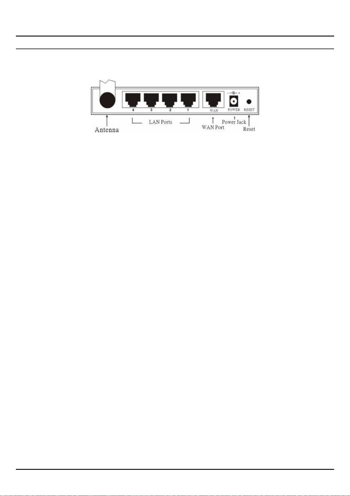
Rear Panel
The figure below shows the rear panel of the 108Mbps Super-GTM Wireless LAN
Router.
Rear Panel
Antenna
There is one 2dBi Gain Antenna in the rear panel for wireless connection.
LAN (1-4)
Four RJ-45 10/100Mbps Auto-MDIX ports for connecting to either 10Mbps or
100Mbps Ethernet connections.
WAN
In the four port broadband router, there is an RJ-45 10/100Mbps Auto-MDIX port
for the WAN that will fit the xDSL/Cable modem’s specification need.
DC IN
Plug the power adapter to this power jack
RESET
Use a pin-shape item to push to reset this device to factory default settings. It will
be useful too when the manager forgot the password to login, but the setting will be
back to default setting.
6
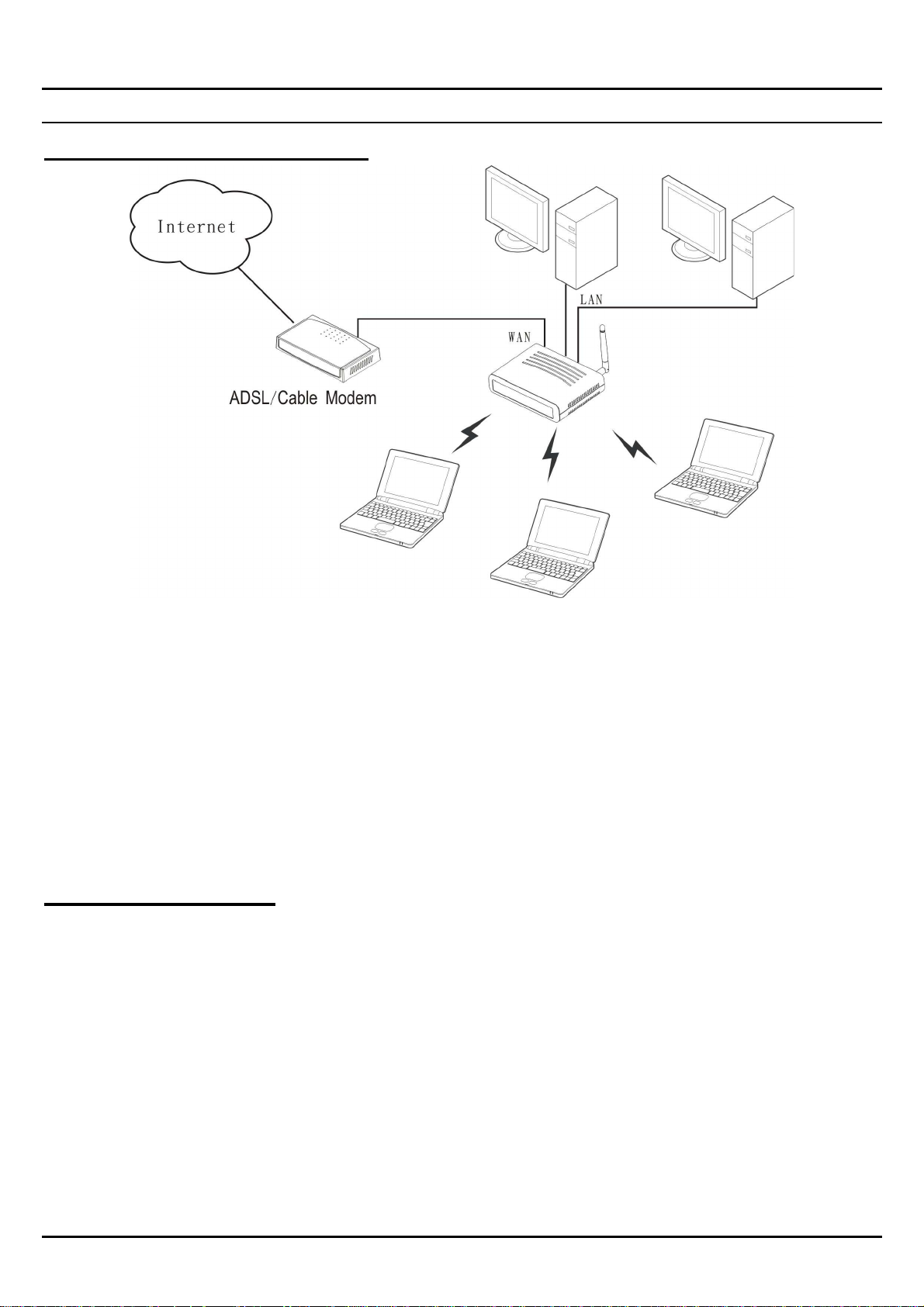
Hardware connections
Connecting the WLAN Router
1. Plug in one end of the network cable to the WAN port of the WLAN Router.
2. Plug in the other end of the network cable to the Ethernet port of the xDSL or
Cable modem.
3. Use another network cable to connect to the Ethernet card on the computer
system; the other end of the cable connects to the LAN port of the WLAN
Router. Since the 108Mbps Super-GTM Wireless LAN Router has four ports, you
can connect up to four computers directly to the unit. There you do not have to
buy a switch to connect these computers since one WLAN Router functions both
as a connection-sharing unit and as a switch.
Check the installation
The control LEDs of the WLAN Router are clearly visible and the status of the
network link can be seen instantly:
1. With the power source on, once the device is connected to the broadband modem,
the Power, System, LAN, WLAN and WAN port LEDs of the WLAN Router
will light up indicating a normal status.
2. While the WAN is link up to the ADSL/Cable modem, the WAN port’s LED
will light up.
3. While the LAN is link up to the computer system, the LAN port’s LED will light
up.
7

PC NETWORK TCP/IP SETTING
The network TCP/IP settings differ based on the computer’s operating system
(Win95/98/ME/NT/2000/XP) and are as follows.
Windows 95/98/ME
1. Click on the “Network neighborhood” icon found on the desktop.
2. Click the right mouse button and a context menu will be show.
3. Select “Properties” to enter the TCP/IP setting screen.
4. Select “Obtain an IP address automatically” on the “IP address” field.
5. Select “Disable DNS” in the “DNS” field.
8
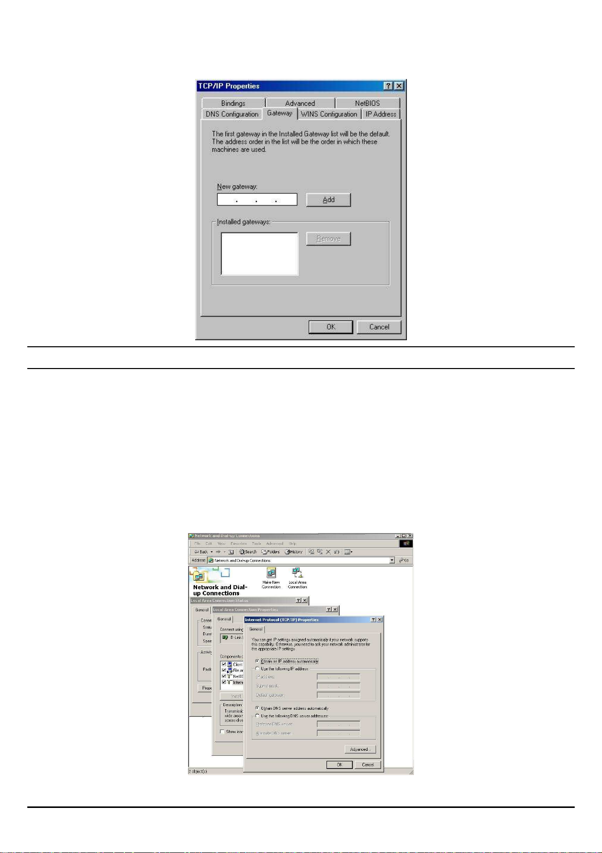
6. Select “None” for the “Gateway address” field.
Windows 2000
Double click on the “My computer” icon on the desktop. When “My computer”
window opens, open the “Control panel” and then open the “Network dialup
connection” applet. Double click on the “Local area network connection” icon.
Select “Properties” to enter the TCP/IP setting window.
1. In the “Local area network status” window, click on “Properties.”
2. In the “Local area network connection” window, first select TCP/IP setting
and then select “Properties.”
3. Set both “IP address” and “DNS” to Automatic configuration.
9
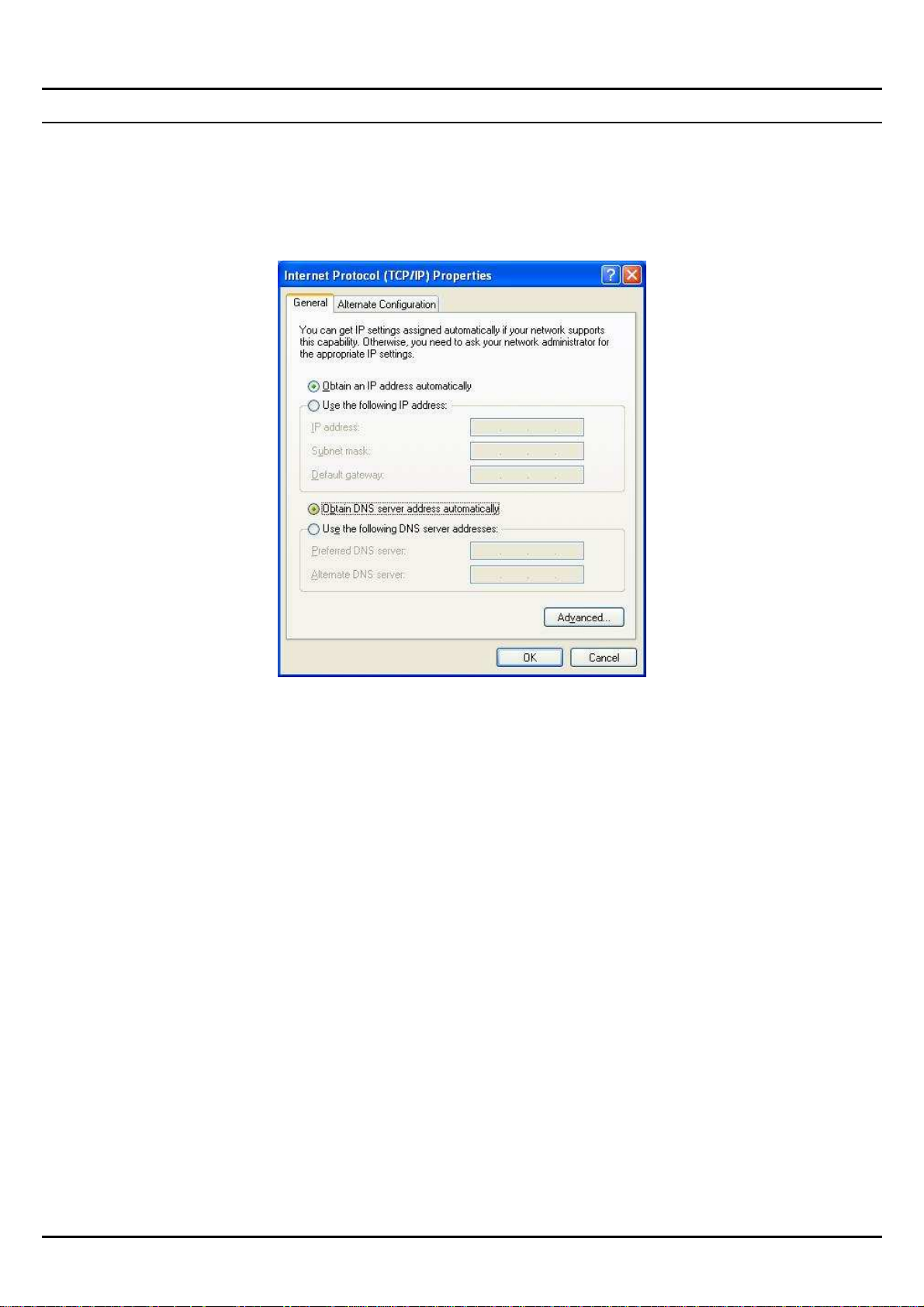
Windows XP
Point the cursor and click the right button on the “My Network Place” icon.
Select “properties” to enter the TCP/IP setting window.
1. Set “IP address” to “Obtain an IP address automatically.”
2. Set “DNS” to “Obtain DNS server address automatically.”
10

CONFIGURATION
First make sure that the network connections are functioning normally.
This WLAN Router can be configured using Internet Explorer 5.0 or newer web
browser versions.
Login to the WLAN Router through Wireless LAN
Before configuring the WLAN Router through WLAN, make sure that the SSID,
Channel and the WEP is set properly.
The default setting of the WLAN Router that you will use:
SSID: default
Channel: 6
Security: disable
Login to the WLAN Router
Before you configure this device, note that when the WLAN Router, make sure the
host PC must be set on the IP subnetwork that can be accessed by the xDSL/Cable
modem. For example, when the default network address of the xDSL/Cable modem
Ethernet interface is 192.168.1.x, then the host PC should be set at 192.168.1.xxx
(where xxx is a number between 2 and 254), and the default subnet mask is
255.255.255.0.
Using the Web Browser
1. Open Internet Explorer 5.0 or above Internet browser.
2. Enter IP address http://192.168.1.1 (the factory-default IP address setting) to
the URL web address location.
3. When the following dialog box appears, enter the user name and password to
login to the main configuration window, the default username and password is
“admin”.
11
 Loading...