

Camec ELITE 2 Caravan Mover, ELITE 2 EM303 User Manual

ELITE® 2 Caravan
Mover

2
TABLE OF CONTENTS
User Manual
Model: CAMEC ELITE
®
2
EM303
Part No: 043321
For Professional Installation Only
*
Not suitable for rear shackle type suspensions
Updated Jan 2017
CAMEC ELITE® 2 EM303 Ref: ELITE 2 EM303-0715Rev.A.

Package contents (parts list)
Introduction
Intended use
Specifications
Installation - safety guidelines
Installation - mechanical components
Installation - electrical/electronic components
Installation - twin axle
Operation - safety guidelines
Operation - motor units
Operation - remote control handset
Operation - electronic control unit
Operation - getting started
Operation - hitching and unhitching
Maintenance
Troubleshooting
Page 3
Page 4
Page 4
Page 4
Page 5
Page 6
Page 8
Page 10
Page 12
Page 13
Page 14
Page 16
Page 17
Page 18
Page 18
Page 18
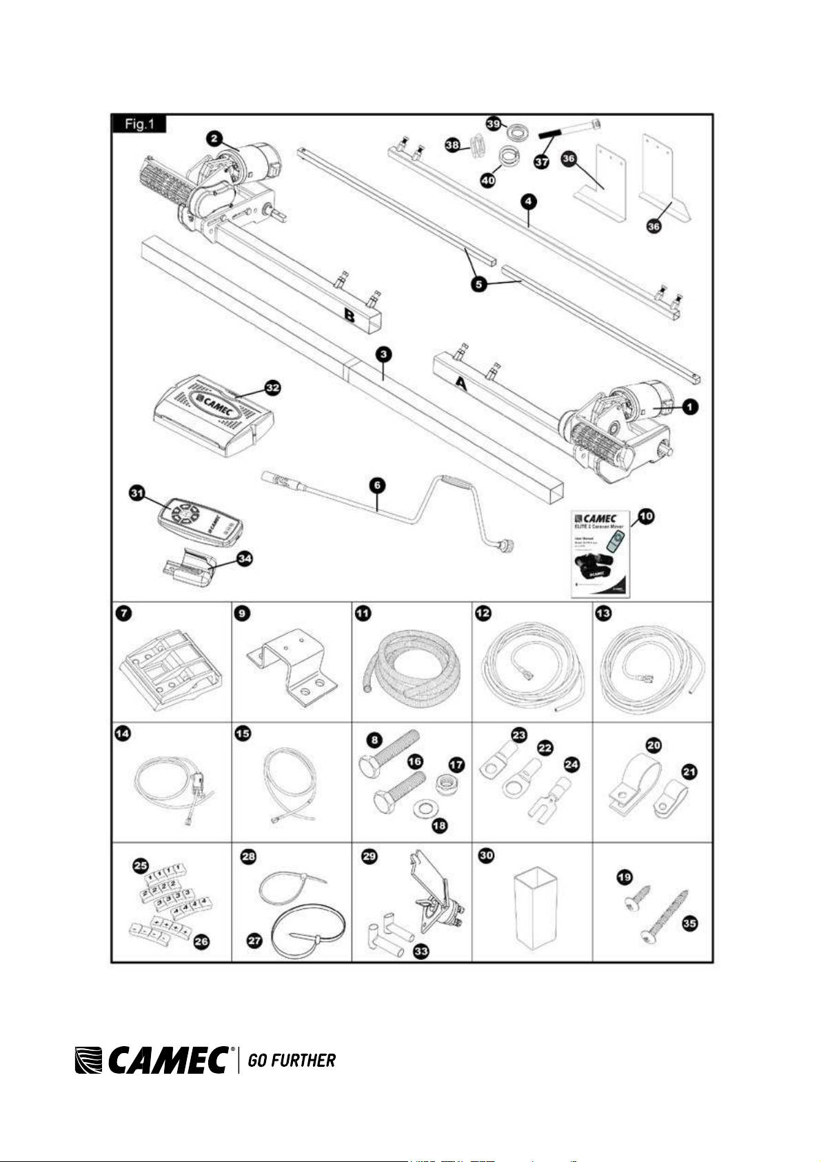
PACKAGE CONTENTS
Ref Qty Description
1 1 Motor unit (A) 2 1
Motor unit (B)
3 1 Main cross bar
4 1 Cross actuation centre bar
5 2 Cross actuation insert bars
6 1 Engagement tool
7 2 Aluminium chassis clamp plates (set)
8 4 Bolt - M10x60
9 2 Chassis U plate
10 1 Instruction manual
11 2 Convoluted cable trunking
12 2 Positive (+) red motor cable 5m
13 2 Negative (-) black motor cable 5m
14 1 Positive (+) red battery cable 1.8m including fuse holder & 80A fuse
15 1 Negative (-) black battery cable 1.6m
16 8 Bolt - M10x50
17 12 Nylon nut M10
18 24 Washer 10mmØ
19 20 Screw - M4x15
20 10 Cable trunking P-clips 19.2mm
21 10 Cable P-clips 10.4mm
22 4 Battery terminal connector 8mmØ
23 2 Battery terminal connector 6mmØ
24 4 Spade fork connector
25 3 Cable number markers (1,2,3,4)
26 3 Cable polarity markers (+,-)
27 4 Motor unit cable ties 8x400
28 10 Cable ties 2x70
29 1 Battery isolation switch, cover & key
30 2 Roller distance spacers 20x20
31 1 Remote control handset with lanyard
32 1 Electronic control unit
33 2 Rubber isolation shell for battery isolation switch
34 1 Remote control handset wall holder
35 2 Screw – M5x40
36 2 Chassis clamp plates (pair) with bolts M8x70, nuts and washers
37 6 Bolt - M8x70
38 6 Nylon nut M8
39 12 Washer 8mmØ
40 6 Spring washer 8mmØ
CAMEC ELITE® 2 EM303 Ref: ELITE 2 EM303-0715Rev.A.
3
4
Package Contents
CAMEC ELITE® 2 EM303 Ref: ELITE 2 EM303-0715Rev.A.
INTRODUCTION
Designation
Camec Elite® 2 EM303
Operational voltage
12 Volt DC
Average current consumption
20 Ampere
Maximum current consumption
100 Ampere
Speed
approx. 9cm per sec.
Weight (2 motor set)
approx. 37kg (excludes battery)
Permissible overall Weight single axle (2 motors)
1800kg (1500kg on 18% gradient)
Permissible overall Weight double axle (2 motors)
1800kg (1500kg on 18% gradient)
Permissible overall Weight double axle (4 motors)
2500kg (1800kg on 18% gradient)
Minimum width (caravan/trailer)
1800mm
Maximum width (caravan/trailer)
2500mm
Maximum tyre width
205mm
Power source (battery)
LiFePO4: 12V, 20Ah (recommended Camec Elite® 2
EM303) Lead acid: 12V, 80Ah (min.)
Congratulations on choosing the Camec Elite® 2 EM303 caravan manoeuvring system. This has been produced
according to very high standards and has undergone careful quality control procedures.
By using the remote control handset you can move your caravan effortlessly into any position required within
operating guidelines. Soft start and soft stop technology allows you to manoeuvre your caravan accurately without
any shocks.
The caravan manoeuvring system consists of two 12V motor-power rollers, a 12V electronic control unit and a
remote control handset. To function, the motor-powered rollers must be engaged against the tyres of your caravan.
The supplied cross actuation device enables you to engage both rollers at the same time from one side of your
caravan. Once this is done, the manoeuvring system is ready for operation. The remote control will allow you to
move your caravan in any direction. You can even rotate the caravan on its own axis, (function not compatible with
double axle caravans) without moving forwards or backwards.
Before proceeding with installation and starting to use the manoeuvring system, please read
this manual very carefully and be aware of all the safety instructions! The owner of the caravan
will always be responsible for correct use. Keep this manual inside your caravan for future
reference.
INTENDED USE
The Camec Elite® 2 EM303 caravan manoeuvring system is suitable for single axle and double axle caravans.
5
Suitable only for L-profiled and U-profiled chassis with a chassis thickness
between min. 2.8mm and max.
3.5mm.
Depending on the weight of the caravan, the manoeuvring system cannot overcome obstructions that are more
than about 2cm in height without assistance (please use wedges as a ramp).
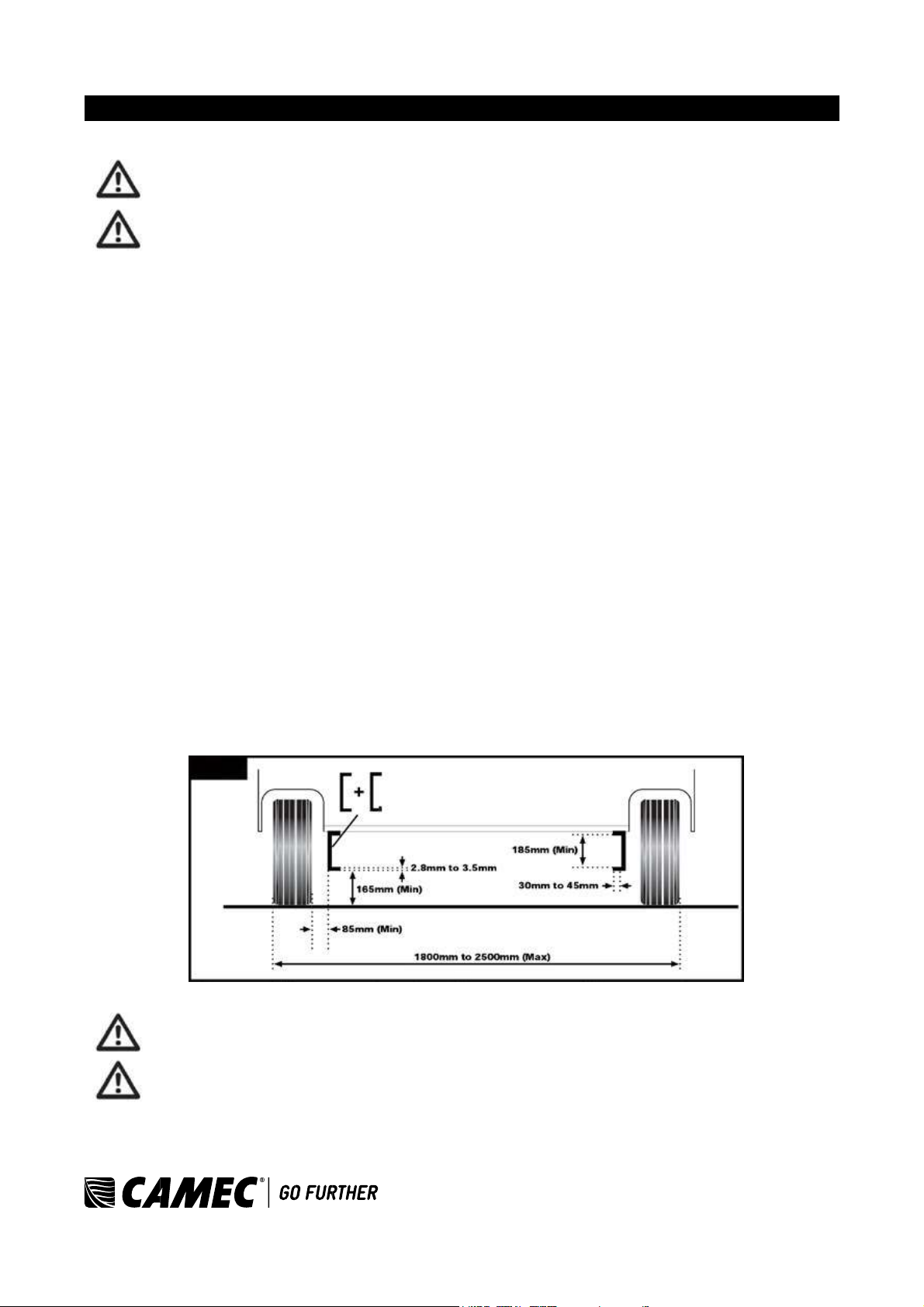
The standard installation kit only provides parts for installing the caravan manoeuvring system within the
measurements given in Fig. 2.
SPECIFICATIONS
CAMEC ELITE® 2 EM303 Ref: ELITE 2 EM303-0715Rev.A.
6
Fig. 2
INSTALLATION - SAFETY GUIDELINES
Read this user manual carefully before installation and use. Failure to comply with these rules
could result in serious injury or damage to property.
These symbols identify important safety precautions. They mean CAUTION! WARNING!
SAFETY FIRST! IMPORTANT INFORMATION!
Before starting installation under the caravan:
• Check the towing load of your vehicle and the gross weight of your caravan in order to establish whether they
are designed for the additional weight. The manoeuvring system itself has a weight of about 37kg and a battery
has a weight of about 20-25kg.
• Check the minimal installation dimensions of the manoeuvring system
based on figure 2.
• Check that the caravan is disconnected from the battery supply and the mains electrical supply.
• Only use adapters and accessories that are supplied or recommended by the manufacturer.
• Check that the tyres are not worn and do have the same size
and design (fitting to new or nearly new tyres is the best option).
• Make sure that the tyre-pressures are correct to the manufacturer’s recommendation.
• Make sure the chassis is in good condition without any damage and is free from rust, dirt etc.
• Stop work immediately if you are in doubt about the assembly or any procedures and consult one of our
engineers (please refer to contact information on the last page of this manual).
• Locate the battery isolation switch. It must be accessible at all times when parking and moving the caravan.
• Do not remove, change or alter any parts of the chassis, axle, suspension or brake mechanism. Any drilling of
holes in the chassis is not allowed.
• Do not install the unit if you are under the influence of
drugs, alcohol or medication that could impair your ability to use the
equipment safely.
INSTALLATION - MECHANICAL COMPONENTS
FOR PROFESSIONAL INSTALLATION ONLY. These instructions are for general guidance.
Installation procedures may vary depending on caravan type.
Working under a vehicle without appropriate support is extremely dangerous!
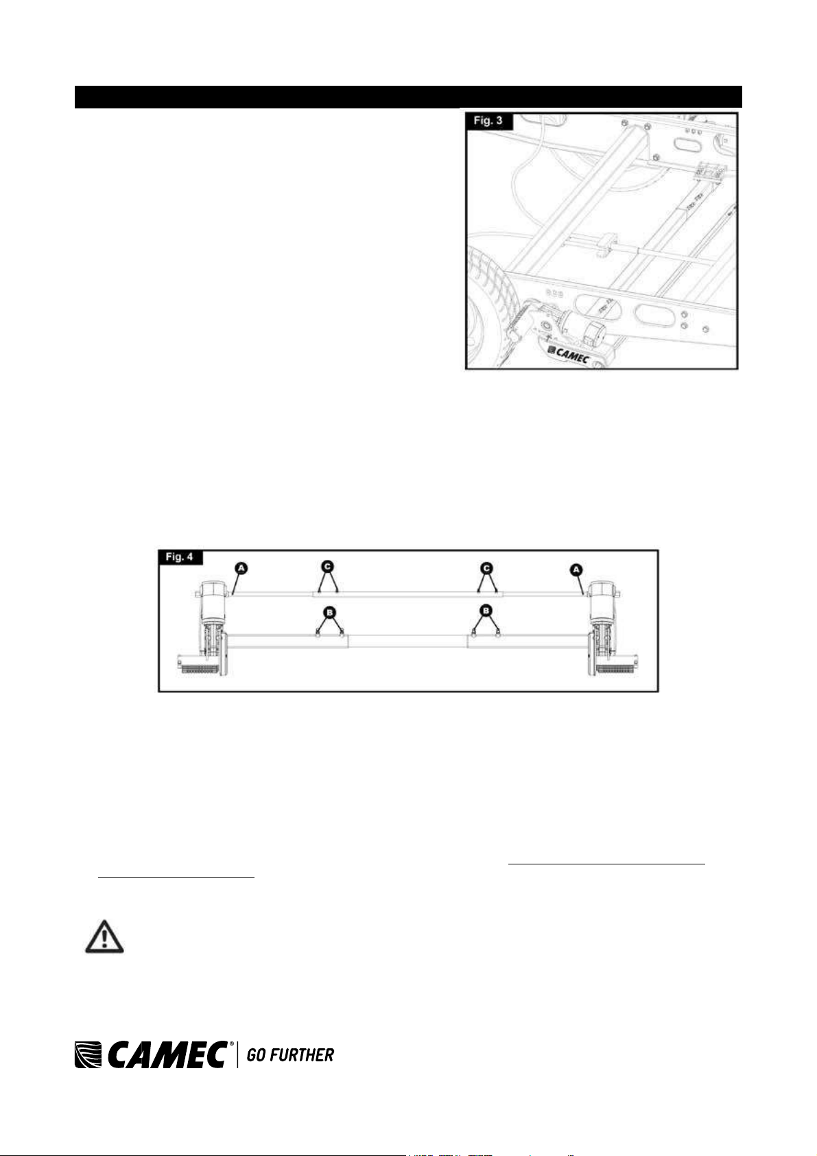
Please refer to figure 3 for an overview of the whole assembly fully fitted.
CAMEC ELITE® 2 EM303 Ref: ELITE 2 EM303-0715Rev.A.
• Place the caravan on a hard, level surface. The use of a
lifting ramp or an assembly pit is ideal for access and
personal safety.
• Unpack all the components and check for the presence of all
parts (see package contents list pg. 2). Write down, on the
product warranty registration card, the 10-digit serial number
(this is located on an aluminium plate on the side of one of
the motor units).
• Clean the area of your chassis where you need to mount all
components to ensure a good fitting.
• Make sure the caravan is prepared for installation. Check
before installation that important areas, such as drains/spare
tyre, etc. do not cause any obstruction to the function of the
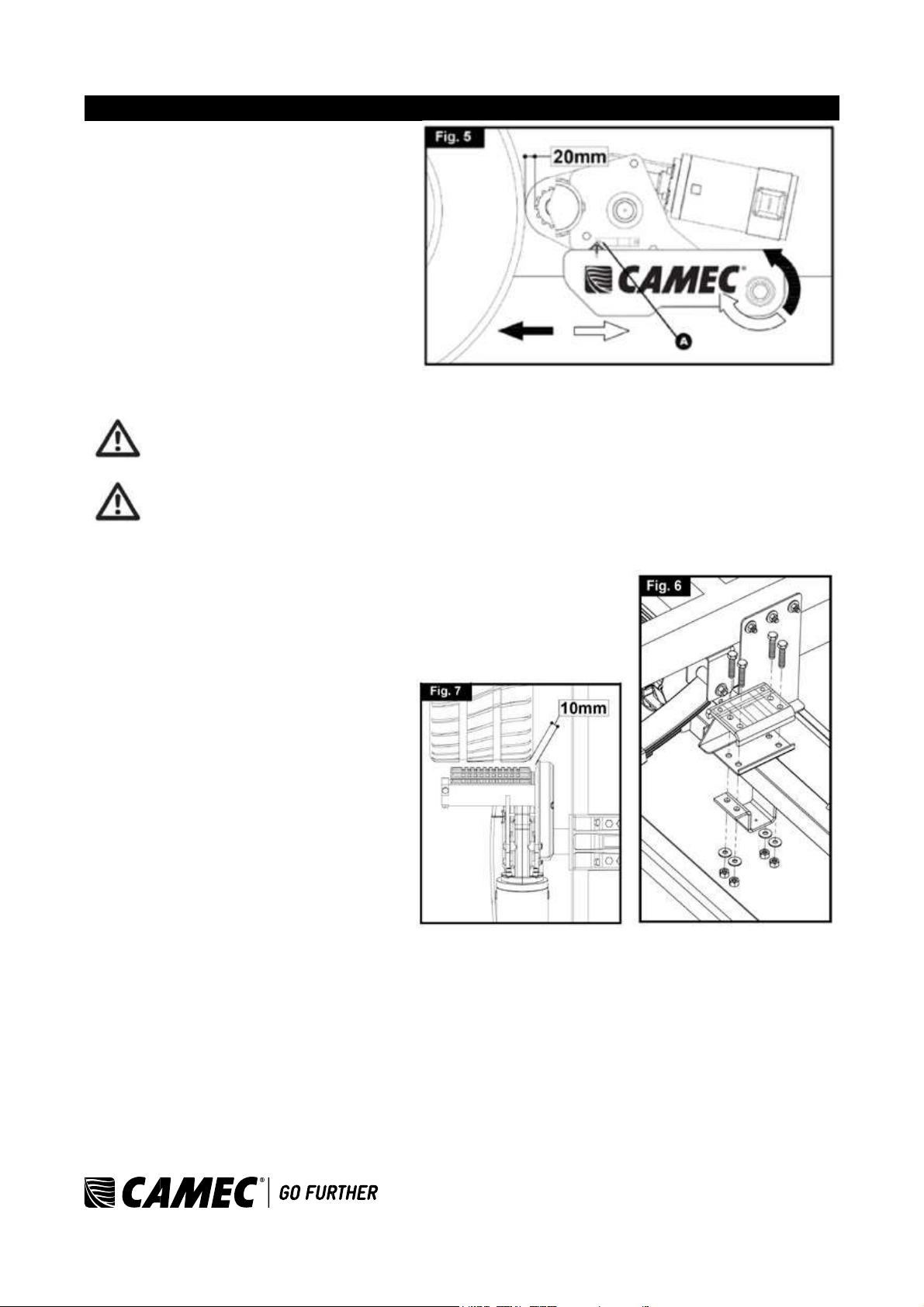
caravan manoeuvring system. • Ensure both rollers
are in the DISENGAGED position (Fig. 5A), as the
unit will not fit correctly otherwise
(Note: when fully disengaged, the pointer is
positioned in the beginning of the yellow area).
• Loosely assemble the left hand motor unit (1), right hand motor unit (2) and main cross bar (3) (Fig. 4). The
nuts (Fig. 4B), on the cross bar (3) to secure both motor units,
must be no more than finger-tight at this stage.
7
Note: In principle, the unit should be fitted in front of the
caravan road wheels, but if fitting in this position is not possible
because of obstacles or a too high hitch ball weight, it is
permissible to fit it to the rear of the wheels by
rotating the whole assembly (Fig. 4) by 180° degrees.
• Fit the Chassis Clamp Plates (36) to the chassis using bolts (37),nuts (38), washers (39) and spring washers
(40), then loosely fit the two aluminium clamp plates (7) to the
plates (36) (Fig. 6 & 3) and attach. Use the bolts M10x60,
nuts M10 and washers M10 (8,17,18) and put them in the diagonal positioned holes of the aluminium chassis
clamp plates. Nuts must be no more than finger-tight.
• Assemble the pre-mounted manoeuvring system on the aluminium chassis clamp plates (7) by using the two U-
shaped brackets (9), bolts M10x50, nuts M10 and washers M10 (16,17,18). Nuts must be no more than fingertight.
• Make sure that aluminium drive rollers of the motors are approximately on the same altitude as the centre
(axle) of the caravan wheel (± 20mm). To compensate a possible unevenness (and lower the motors), Camec
Elite® 2 has a set of distance plates available. One set can compensate 15mm. In total three sets can be used
so that an altitude of 45mm can be compensated.
Adequate ground clearance: Please notice that the min. distance between the lowest line of
motors and ground is 110mm, no matter what kinds chassis or install situation.
CAMEC ELITE® 2 EM303 Ref: ELITE 2 EM303-0715Rev.A.
8
• Assemble the parts of the cross actuation bar
(4 & 5) and connect them to the motor units
(1 & 2) with the nylon nut and bolt (factory
fitted) onto the cross
actuation bar-connectors (Fig. 4
& Fig. 4A). Nuts must be no more than
finger-tight at this stage.
• Make sure that the main cross bar (12) and
the cross actuation centre bar (4) are
positioned in the middle of the caravan (the
centre of the bar is marked).
• When the main assembly
is loosely fitted onto the
chassis, slide the whole assembly along the
chassis until the rollers are 20mm away from the surface of the centre each tyre (Fig. 5). Two 20mm spacers
(30) are provided.
It is vitally important that each roller is at exactly the same distance away from the tyre. The
whole assembly must be parallel to the caravan/trailer axle.
Slide the motor units in or out of the cross bar (3) accordingly to ensure the roller will have the
maximum possible contact with the tread of the tyre. Ensure that the position of each motor
unit does not obstruct shock absorbers (if fitted) and that the gear cover (Fig. 7) is not too close
to the surface of the tyre/shock absorber. The minimum clearance when the drive units
swivelled in is 10mm.
• Fully tighten the four bolts (Fig. 4B) on the
main cross bar (3) and the four bolts (Fig.
4C) on cross actuation assembly (4 & 5).
• Fully tighten all the nylon nuts on both
clamping assemblies (Fig. 6). First tighten
the diagonal placed M10x60 bolts with a
20Nm torque, and then M10x50 bolts to a
40Nm torque.
• Re-check the distance of 20mm from the
rollers to the tyres, the position of the
aluminium rollers in addition to the surface
of the tyre and finally the
distance between the plastic gear cover
(Fig. 7) and the tyres & shock absorbers
(>10mm). The weight of the caravan musty
be on the wheels when doing this. If
necessary, loosen the bolts and re-adjust
the position of the assembly.
The main mechanical components have now
been installed.
CAMEC ELITE® 2 EM303 Ref: ELITE 2 EM303-0715Rev.A.
 Loading...