

Page 1
Sliding gate operator
EN
English
OPS series
FA01084-EN
OPS001
INSTALLATION OPERATION AND MAINTENANCE MANUAL
Page 2
4
3
2
1
1
2
3
Page 3

GENERAL PRECAUTIONS FOR INSTALLERS
⚠ WARNING! Important safety instructions.
Follow all of these instructions. Improper installation can cause serious bodily
harm.
Before continuing, also read the general precautions for users.
This producT musT only be used for iTs specifically inTended purpose. any oTher use is dangerous.
cameS.P.A.is noT liable for any damage caused by improper, wrongful and unreasonable use. • This
manual's producT is defined by machinery direcTive 2006/42/ce as "parTly-compleTed machinery".
Quasi-compleTed machinery is parTly-compleTed machinery is a seT ThaT almosT consTiTuTes a machine,
buT which, alone, cannoT ensure a clearly defined applicaTion. parTly-compleTed machinery is only
desTined To be incorporaTed or assembled To oTher machinery or oTher parTly-compleTed machinery
or apparaTuses To build machinery ThaT is regulaTed by direcTive 2006/42/ce. The final insTallaTion
musT be complianT wiTh european direcTive 2006/42/ce and currenT european reference sTandards.
given These consideraTions, all procedures sTaTed in This manual musT be exclusively performed by
experT, Qualified sTaff. • The manufacTurer declines any liabiliTy for using non-original producTs;
which would resulT in warranTy loss • Keep This manual inside The Technical folder along wiTh The
manuals of all The oTher devices used for your auTomaTion sysTem. • checK ThaT The TemperaTure
range shown on The operaTor is suiTable To The locaTions where iT will be insTalled. • laying The
cables, insTallaTion and TesTing musT follow sTaTe-of-The-arT procedures as dicTaTed by regulaTions
• if The power-supply cable is damaged, iT musT be immediaTely replaced by The manufacTurer or by
an auThorized Technical assisTance cenTer, or in any case, by Qualified sTaff, To prevenT any risK •
during all phases of The insTallaTion maKe sure you have cuT off The mains power source. • The
operaTor cannoT be used wiTh gaTes fiTTed wiTh pedesTrian doors, unless iTs operaTion can be acTiva-
Ted only when The pedesTrian door is in safeTy posiTion. • maKe sure ThaT people are noT enTrapped
beTween The gaTe's moving and fixed parTs due To The gaTe's movemenT. before insTalling The opera-
Tor, checK ThaT The gaTe is in proper mechanical condiTion, ThaT iT is properly balanced and ThaT iT
properly closes: if any of These condiTions are noT meT, do noT conTinue before having meT all safeTy
reQuiremenTs. • maKe sure The gaTe is sTable and The casTors funcTion properly and are well-grea-
sed, and ThaT iT opens and closes smooThly. • The guide rail musT be well-fasTened To The ground,
enTirely above The surface and free of any impedimenTs To The gaTe's movemenT. • The rails of The
upper guide musT noT cause any fricTion. • maKe sure ThaT opening and closing limiTers are fiTTed •
maKe sure The operaTor is insTalled onTo a sTurdy surface ThaT is proTecTed from any collisions •
maKe sure ThaT mechanical sTops are already insTalled • if The operaTor is insTalled lower Than 2.5
from The ground or from any oTher access level, fiT any proTecTions and signs To prevenT hazardous
siTuaTions. • do noT fiT The operaTor upside down or onTo elemenTs ThaT could yield To iTs weighT. if
necessary, add reinforcemenTs To The fasTening poinTs • do noT insTall door or gaTe leaves on TilTed
surfaces • checK ThaT no lawn waTering devices spray The operaTor wiTh waTer from The boTTom up.
• any residual risKs musT be indicaTed clearly wiTh proper signage affixed in visible areas. all of
which musT be explained To end users. • suiTably secTion off and demarcaTe The enTire insTallaTion
siTe To prevenT unauThorized persons from enTering The area, especially minors and children. • affix
cauTionary signs, such as The door plaTe, The gaTe plaTe, wherever needed and in plain sighT. • use
proper proTecTions To prevenT mechanical hazards when people are loiTering around The machinery's
range of acTion, for example To prevenT finger crushing beTween The racK and pinion) • The elecTrical
cables musT run Through The cable glands and musT noT Touch any heaTed parTs, such as The moTor,
Transformer, and so on). • maKe sure you have seT up a suiTable dual pole cuT off device along The
power supply ThaT is complianT wiTh The insTallaTion rules. iT should compleTely cuT off The power
supply according To caTegory iii surcharge condiTions. • all opening conTrols musT be insTalled aT
leasT 1.85 m from The perimeTer of The gaTe's worKing area, or where They cannoT be reached from
ouTside The gaTe. • all swiTches in mainTained acTion mode musT be posiTioned so ThaT The moving gaTes
leaves, The TransiT areas and vehicle Thru-ways are compleTely visible, and yeT The swiTches musT be
also away from any moving parTs • unless The acTion is Key operaTed, The conTrol devices musT be
fiTTed aT, aT leasT, 1.5 m from The ground and musT noT be accessible To The public. • To pass The
collision force TesT use a suiTable sensiTive safeTy-edge. insTall iT properly and adjusT as needed. •
before handing over To users, checK ThaT The sysTem is complianT wiTh The 2006/42/ce uniformed
machinery direcTive. maKe sure The seTTings on The operaTor are all suiTable and ThaT any safeTy and
proTecTion devices, and also The manual release, worK properly. • affix a permanenT Tag,
p. 3 - Manual FA01084-EN - 02/2018 - © CAME S.p.A. - "Translated original instructions"
Page 4
ThaT describes how To use The manual release mechanism, close To The mechanism. • maKe sure To
hand over To The end user, all operaTing manuals for The producTs ThaT maKe up The final machinery.
-
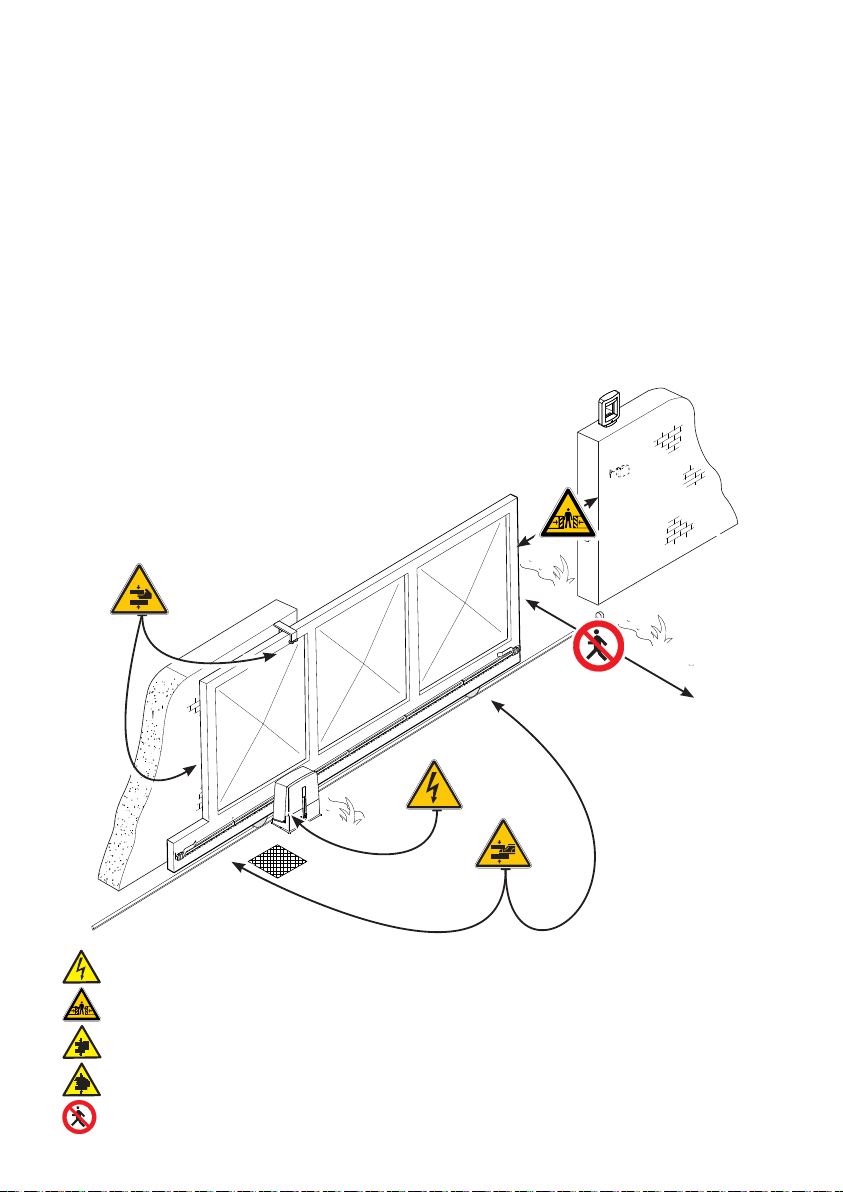
The nexT figure shows The main hazard poinTs for people
-
Danger of high voltage;
Danger of crushing;
Danger of foot crushing;
Danger of hand entrapment;
Do not transit through during maneuvering.
p. 4 - Manual FA01084-EN - 02/2018 - © CAME S.p.A. - "Translated original instructions"
Page 5

KEY
This symbol shows which parts to read carefully.
⚠
☞
The measurements, unless otherwise stated, are in millimeters.
This symbol shows which parts describe safety issues
This symbol shows which parts to tell users about.
DESCRIPTION
Operator with control board, movement control and obstruction detecting device plus mechanical stops for sliding
gates of up to 400 kg and 10 m in length.
INTENDED USE
The operator is designed to power sliding gates in residential and apartment block settings.
Do not install of use this device in any way, except as specified in this manual.
LIMITS TO USE
Type OPS001
Maximum gate-leaf length (m) 10
Maximum gate-leaf weight (kg) 400
Pinion module 4
TECHNICAL DATA
Type OPS001
Protection rating (IP) 44
Power supply (V - 50/60 Hz) 230 AC
Input voltage motor (V) 24 DC
Max draw (A) 7
Stand-by consumption (W) 7.4
Stand-by consumption with the RGP1 (W) module 1.2
Maximum power (W) 150
Duty cycle (%) 50
Operating temperature (°C) -20 to +55
Apparatus class I
Weight (Kg) 7.7
p. 5 - Manual FA01084-EN - 02/2018 - © CAME S.p.A. - "Translated original instructions"
Page 6
117
211
349
160
300
170
298
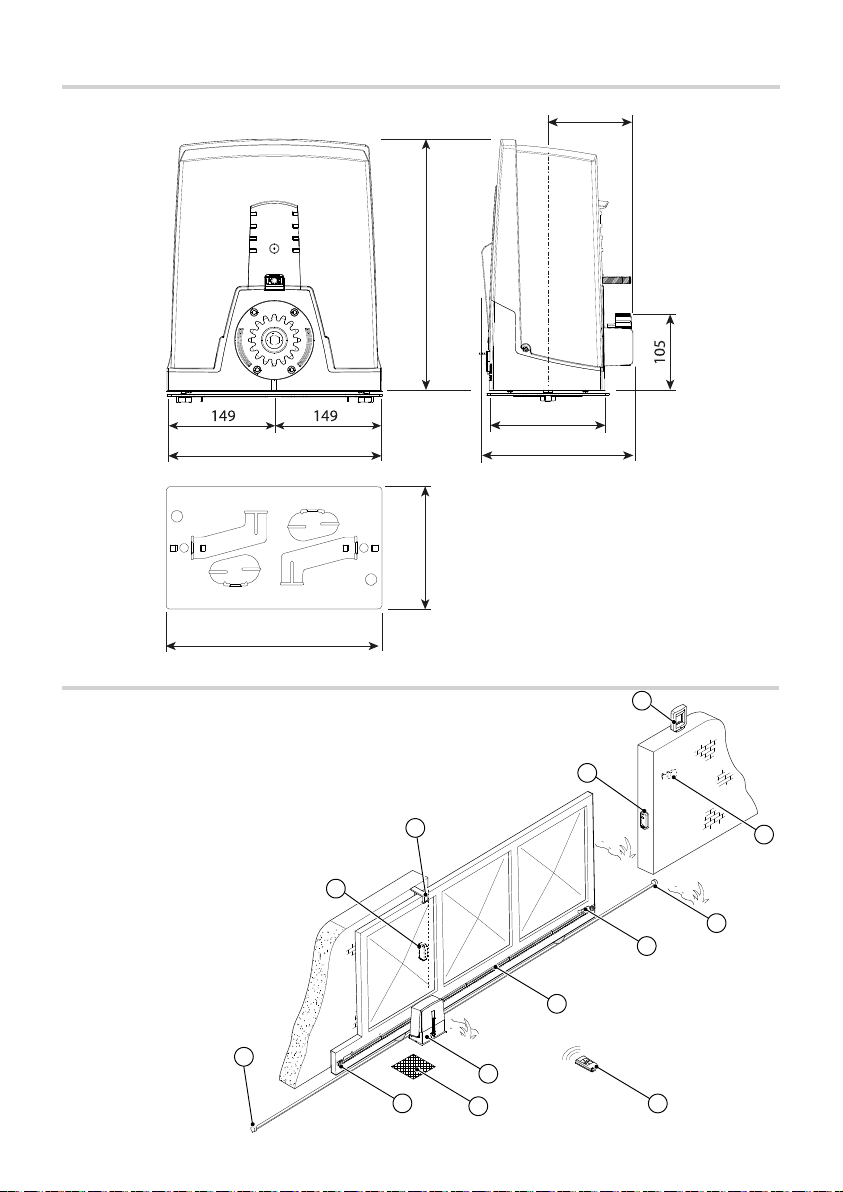
DIMENSIONS (MM)
STANDARD INSTALL ATION
1. Operator
2. Limit-switch fins
3. Rack
4. Key-switch selector
5. Flashing light
6. Photocells
7. Mechanical gate stop
8. Transmitter
9. Slide guides
10. Junction pit
6
9
5
6
4
7
3
7
2
1
10
2
8
p. 6 - Manual FA01084-EN - 02/2018 - © CAME S.p.A. - "Translated original instructions"
Page 7
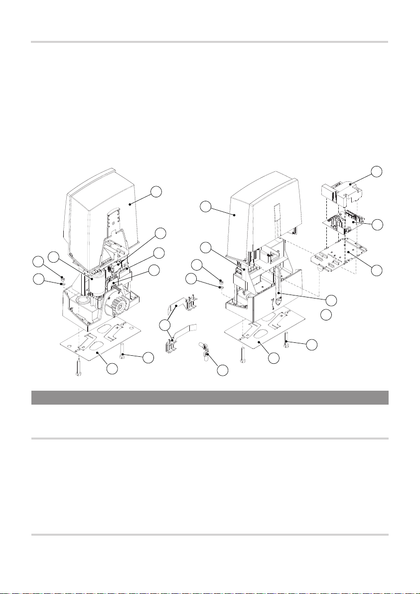
DESCRIPTION OF PARTS
1. Cover
2. Board-fitting support
3. Gear motor
4. Anchoring plate
5. Fastening bolts UNI 5739 M12X60
6. Washer Ø 12
7. Nut UNI 5588 M12
8. Board protecting cover
9. Control board
10. Board-housing
3
7
6
16
1
15
14
13
11. Release lever
12. Lock
13. Limit-switch fins
14. EMC02 card
15. Transformer
16. Endstop device
17. Release key
1
2
7
6
8
9
10
11
12
5
5
4
17
4
GENERAL INSTALLATION INDICATIONS
Only skilled, qualified sta must install this product.
⚠
PRELIMINARY CHECKS
Before beginning the installation, do the following:
⚠
• check that the upper slide-guides are friction-free;
• make sure there is are opening and closing mechanical gate stops;
• make sure that the point where the gearmotor is fastened is protected from any impacts and that the surface
is solid enough;
• set up suitable tubes and conduits for the electric cables to pass through, making sure they are protected from
any mechanical damage.
TOOLS AND MATERIALS
Make sure you have all the tools and materials you will need for installing in total safety and in compliance with
applicable regulations. The figure shows some of the equipment installers will need.
p. 7 - Manual FA01084-EN - 02/2018 - © CAME S.p.A. - "Translated original instructions"
Page 8

CABLE TYPES AND MINIMUM SECTIONS
Connection
Input voltage for 230 V AC control board
(1P+N+PE)
< 20 m 20 < 30 m
3G x 1.5 mm
Signaling devices 2 x 0.5 mm
Command and control devices 2 x 0.5 mm
Safety devices (photocells)
cable length
2
2
2
(TX = 2 x 0.5 mm
(RX = 2 x 0.5 mm2)
3G x 2.5 mm
2
)
2
When operating at 230 V and outdoors, use H05RN-F-type cables that are 60245 IEC 57 (IEC) compliant;
whereas indoors, use H05VV-F-type cables that are 60227 IEC 53 (IEC) compliant. For power supplies up to 48
V, you can use FROR 20-22 II-type cables that comply with EN 50267-2-1 (CEI).
To connect the antenna, use the RG58 (we suggest up to 5 m).
For paired connection and CRP, use a UTP CAT5-type cable (up to 1,000 m long).
If cable lengths differ from those specified in the table, establish the cable sections depending on the actual
power draw of the connected devices and according to the provisions of regulation CEI EN 60204-1.
For multiple, sequential loads along the same line, the dimensions on the table need to be recalculated
according to the actual power draw and distances. For connecting products that are not contemplated in this
manual, see the literature accompanying said products
p. 8 - Manual FA01084-EN - 02/2018 - © CAME S.p.A. - "Translated original instructions"
Page 9

400
50
INSTALLATION
The following illustrations are mere examples. Consider that the space available where to fit the barrier and
⚠
accessories will vary depending on the area where it is installed. It is up to the installer to find the most suitable
solution.
CORRUGATED TUBE LAYING
Dig a hole for the foundation frame.
Set up the corrugated tubes needed for the wiring coming out of the junction pit.
For connecting the gearmotor we suggest using a Ø 40 mm corrugated tube, whereas for the accessories we
suggest Ø 25 mm tubes.
The number of tubes depends on the type of system and the accessories you are going to fit.
300
450
LAYING THE ANCHORING PLATE
Set up a foundation frame that is larger than the anchoring plate and sink it into the dug hole. The foundation frame
must jut out by 50 mm above ground level.
Fit an iron cage into the foundation frame to reinforce the concrete.
Fit the bolts into the anchoring plate and lock them using the washers and nuts. Remove the pre-shaped clamps
using a screw driver or pliers.
UNI 5588 M12
2
p. 9 - Manual FA01084-EN - 02/2018 - © CAME S.p.A. - "Translated original instructions"
UNI 5734
Ø 12
Page 10

If the rack is already there, place the anchoring plate, being careful to respect the measurements shown in the
drawing.
Careful! The tubes must pass through their corresponding holes.
95
105
Fill the foundation frame with concrete. The plate must be perfectly level with the bolts which are entirely above
surface.
Wait at least 24 hrs for the concrete to solidify.
Remove the foundation frame and fill the hole with earth around the concrete block.
Remove the nut and washer from the bolts
Fit the electric cables into the tubes so that they come out about 600 mm.
p. 10 - Manual FA 01084-EN - 02/2018 - © CAME S.p.A. - "Translated original instructions"
Page 11

SETTING UP THE GEARMOTOR
Remove the gearmotor cover by turning the side bolts.
Place the gearmotor above the anchoring plate.
Careful! The electric cables must pass under the gearmotor case.
2
1
Perforate the cable gland and fit it into its housing after threading the cables.
Lift the gearmotor by 5 to 10 mm from the plate by adjusting the threaded steel feet to allow any subsequent
adjustments between pinion and rack.
2
1
3
5 ÷ 10
p. 11 - Manual FA010 84- EN - 02/2018 - © CAME S.p.A. - "Translated original instructions"
Page 12

1 ÷ 2
FASTENING THE RACK
If the rack is already set up, the next step should be to adjust the rack-and-pinion coupling distance, otherwise,
fasten it:
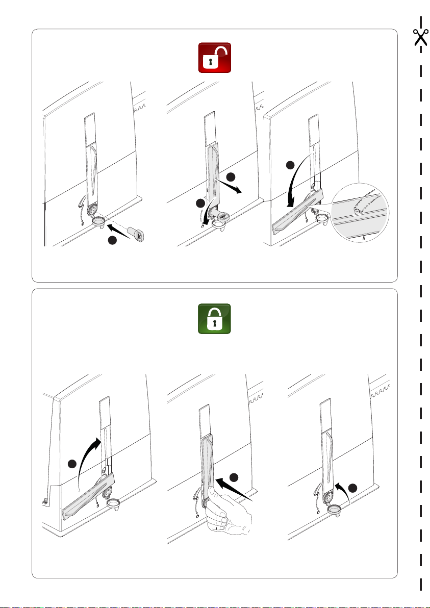
- release the gearmotor (see RELEASING THE GEARMOTOR paragraph);
- rest the rack above the gearmotor pinion;
- weld or fasten the rack to the gate along its entire length.
To assemble the rack modules, use an extra piece and rest it under the joint, then fasten it using two clamps.
ADJUSTING THE PINION-RACK COUPLING
Manually open and close the gate and adjust the pinion-rack coupling distance using the threaded feet (vertical
adjustment) and the holes (horizontal adjustment). This prevents the gate's weight from bearing down on the
operator.
p. 12 - Manual FA01084-E N - 02/2018 - © CAME S.p. A. - "Translated original instructions"
Page 13

FASTENING THE GEARMOTOR
Complete the adjusting, fasten the gearmotor to the plate using the washers and nuts.
ESTABLISHING THE LIMIT-SWITCH POINTS
For opening:
- completely open the gate;
- fit the opening endstop fin onto the rack until the micro switch activates (spring);
- fasten it using the allen screws
2
Spring
1
For closing:
- completely close the gate;
- fit the closing endstop fin onto the rack until the micro-switch activates (spring);
- fasten it using the allen screws
Don't let the gate get to the mechanical stop, whether it is the opening or closing one.
⚠
p. 13 - Manual FA01084-E N - 02/2018 - © CAME S.p. A. - "Translated original instructions"
2
1
Page 14

ELECTRICAL CONNECTIONS AND PROGRAMMING
Caution! Before working on the control panel, cut off the mains power supply and remove any batteries.
⚠
Powering up the control board and command and control devices: 24 V AC/DC.
Careful! The accessories connected onto 10-11 must never exceed 20 W overall.
⚠
Use DIP switches to set functions and the trimmer for adjustments.
All wiring connections are quick-fuse protected.
Fuses
ZN6
- Line 1.6 A-F
- Accessories 2 A-F
DESCRIPTION OF PARTS
1. DIP-SWITCH
2. Trimm er
3. Programming button
4. Alert LED
5. Button Button (7)
6. Encoder and endstop terminals
7. Command and safety devices terminals
8. Keypad selector terminal
9. Terminal for gearmotors
10. Power supply to accessories terminal
11. Power supply to control board terminal
12. Accessories / board fuse
13. Antenna terminal
14. AF card slot
15. Green power module terminal
16. R800 card connector
17. Power supply terminal board
18. Line fuse
18
17
1
2
4
3
5
6
16
15
14
13
12
7
8
9
10
11
p. 14 - Manual FA01084-EN - 02/2018 - © CAME S.p.A. - "Translated original instructions"
Page 15

M N
A B 1 2 3P 7
10 TS 2 CX
+ E -
FC FA F
L
N
+ E -
M N24 0 10 11 E
A B 1 2 3P 7
10 TS 2 CX
+ E -
FC FA F
M N24 0 10 11 E
A B 1 2 3P 7
10 TS 2 CX
+ E -
FC FA F
INPUT VOLTAGE
Power supply 230 V AC 50/60 Hz
-
Accessories power supply output 24 V AC/DC, max 20 W
+
+
24 0 10 11 E
-
Control board power supply 24 V AC/DC
CONNECTING THE GEARMOTOR WITH ENCODER AND ENDSTOPS
Opening limit-switch (NC contact)
Closing limit-switch (NC contact)
FC FA F
SIGNALING DEVICES
Green
Brown
White
Encoder
24 V DC gearmotor
M
Flashing light (Contact rating 24 V AC/DC - 25 W max)
p. 15 - Manual FA 01084-E N - 02/2018 - © CAME S.p.A. - "Translated original instructions"
Page 16

M N24 0 10 11 E
A B 1 2 3P 7
10 TS 2 CX
+ E -
FC FA F
+ E -
FC FA F
AF
R800
COMMAND AND CONTROL DEVICES
WARNING! For the system to work properly, before fitting any plug-in card, such as the AF or R800 one, you
⚠
MUST CUT OFF THE MAINS POWER SUPPLY and, if present, disconnect any batteries.
Connector for the R800 card (the
R800 card is for using the keypad
selector)
10 TS 2 CX
A B 1 2 3P 7
Antenna RG58 cable for remote control
Connector for AF card (AF868 or AF43S) for remote control
OPEN-CLOSE-INVERT function (step-step) from
control device (NO contact). Alternatively, from
functions programming you can activate the
OPEN-STOP-CLOSE-STOP command.
PARTIAL OPENING feature from command device
(NO contact).
STOP STOP(N.C. contact). For stopping the gate
while excluding automatic closing. To resume movement press the control button or use another
control device.
If unused, it should be deactivated during programming.
Blue
Keypad selector
White
To be able to snap in the cards into the dedicated connectors, raise the card cover.
OK
p. 16 - Manual FA 01084-EN - 02/2018 - © CAME S.p.A. - "Translated original instructions"
Page 17

10 2 T X
C
NC
SAFETY DEVICES
Photocells
Configure the CX contact (NC), input for safety devices such as photocells.
When programming the functions the CX input may be set up as:
- C1 reopening during closing. When the gate is closing, opening the contact
triggers the inversion of movement until the gate is fully open again;
- C4 obstruction wait. Stopping of the gate, if it is moving, which resumes
movement once the obstruction is removed.
If unused, the CX contact should be deactivated during programming.
Connecting the safety devices (i.e. the safety test)
At each opening and closing command, the control board checks the ecacy of the safety devices (such as,
photocells).
Any anomalies will inhibit all commands.
Enable this function when programming.
-
+
+
-
-
+
+
-
10 2 T X
-
2
TX 2
TX
DN10
-
2
TX 2
C
NC
TX
DN10
FUNCTIONS PROGRAMMING
DIP-SWITCH
IMPORTANT! Start programming while respecting the order of the features shown on the list below.
Only program functions when the operator is stopped.
⚠
When programming is finished, set all Dip-switches to OFF.
You can save up to 25 users.
IMPORTANT! Start programming by first running the Opening direction, TOTAL STOP and Self-
learning functions, respectively.
DIP-SWITCH Description of functions
Opening direction
By default, the operator is programmed for being installed on the left.
For installing on the right:
select the DIPs as shown and press the P1 key on the card. The LED stays on and the buzzer sounds
off for one second.
Press P1 to return to the default parameters. The LED blinks and the buzzer sounds off twice.
p. 17 - Manual FA01084- EN - 02/2018 - © CAME S.p.A. - "Translated original instructions"
P1 key
Red LED (PRG)
Page 18

TOTAL STOP from button (contact 1-2)
By default, the feature is enabled.
To disable it:
select the DIP switches as shown and press the P1 key on the card. The LED blinks and the buzzer
sounds off twice.
To return to the default parameters, press P1 again. The LED stays lit and the buzzer sounds off for 1
second.
Self-learningof the gate-leaf travel
Select the DIP switches as shown and press the P1 key on the control board.
The gate will perform a series of maneuvers to determine the endstop slow-down points.
During calibration the red LED blinks. Once the calibration is complete, the buzzer sounds off for 1
second.
If the calibration has not succeeded, the LED blinks quickly and the buzzer sounds off 4 times.
You can interrupt the gate travel's self-learning operation by pressing key P1.
Input on contact 2-CX
By default,the feature is disabled.
To enable it:
Select the DIP switches as shown and press the P1 button on the control board. The LED stays on and
the buzzer sounds off for one second.
To return to the default setting, press P1 again. The LED blinks and the buzzer sounds off twice.
Reopening during closing or obstruction wait (contact 2-CX)
By default, the feature is set to reopening during closing.
To enable on obstruction wait:
select the DIP switches as shown and press the P1 button on the control board. The LED stays on and
the buzzer sounds off for one second.
To return to the default settings, press P1 again. The LED blinks and the buzzer sounds off twice.
Self-learningof the partial gate-travel
Using the control button (7) on the control board, take the gate to the desired partial opening position.
Select the DIP switches as shown and press the P1 key on the control board. The LED stays on and the
buzzer sounds off for one second.
To return to the default setting, press P1 again. The LED blinks and the buzzer sounds off twice.
If the partial opening is not within the minimum and maximum limits set by default, the LED
blinks quickly and the buzzer sounds off 4 times.
OPEN-CLOSE-INVERT or OPEN-STOP-CLOSE-STOP with button (contac t 2-7)
By default, the feature is OPEN-CLOSE-INVERT.
To enable it to OPEN-STOP-CLOSE-STOP:
select the DIPs as shown and press the P1 key on the on the control board. The LED stays on and the
buzzer sounds off for one second.
To return to the default settings, press P1 again. The LED blinks and the buzzer sounds off twice.
Automatic closing
By default, the feature is disabled.
To enable it:
select the DIPs as shown and press the P1 key on the control board. The LED stays on and the buzzer
sounds off for one second.
Toreturn to the default setting, press P1 again. The LED blinks and the buzzer sounds off twice.
The wait before the automatic closing starts when the opening limit-switch point is reached - for a time
that is settable on the A.C.T. trimmer.
The automatic closing does not activate if the safety devices are triggered due to obstacle detection,
⚠
after a total stop or if the power supply is missing.
p. 18 - Manual FA01084-E N - 02/2018 - © CAME S.p.A. - "Translated original instructions"
Page 19

Automatic closing after partial stop
By default, the feature is enabled.
To disable it:
select the DIP switches as shown and press the P1 key on the card. The LED blinks and the buzzer
sounds off twice.
To return to the default setting, press P1 again. The LED stays on and the buzzer sounds off for 1 s.
⚠ When the feature is disabled, after an opening command, the gate automatically closes until the
previously set partial opening point.
To completely close the gate send a 2-7 command from a button or transmitter.
Services test
By default, the feature is disabled.
To enable it:
select the DIPs as shown and press the P1 key on the control board. The LED stays on and the buzzer
sounds off for one second.
To return to the default setting, press P1 again. The LED blinks and the buzzer sounds off twice.
Obstruction detection with motor stopped
By default, the feature is disabled.
To enable it:
Select the DIP switches as shown and press the P1 key on the control board. The LED stays on and the
buzzer sounds off for one second.
To return to the default setting, press P1 again. The LED blinks and the buzzer sounds off twice.
Encoder
By default, this function is enabled.
To disableit:
select the DIP switches as shown and press the P1 key on the control board. The LED blinks and the
buzzer sounds off twice.
To return to the default setting, press P1 again. The LED stays on and the buzzer sounds off for 1 s.
Button-activated maintained action
By default, the feature is disabled.
To enable it:
select the DIPs as shown and press the P1 key on the control board. The LED stays on and the buzzer
sounds off for one second.
To return to the default setting, press P1 again. The LED blinks and the buzzer sounds off twice.
The gate opens and closes when the button is kept pressed.
⚠
Opening button connected on 2-3P (NO contact) and closing button connected on 2-7 (NO contact)
All other control devices, even radio-based ones, are excluded.
Pre-flashing (pre-flashing duration: 5 s)
By default, the feature is disabled.
To enable it:
select the DIPs as shown and press the P1 key on the control board. The LED stays on and the buzzer
sounds off for one second.
To return to the default setting, press P1 again. The LED blinks and the buzzer sounds off twice.
Adjusting the maneuver speed
The defaultmaneuver speed is set to 100%.
To diminish the maneuver speed by 40%:
select the DIP switches as shown and press P1 on the control board. The red LED stays lit and buzzer
sounds off for one second.
To return to the default setting, press P1 again. The LED blinks and the buzzer sounds off twice.
p. 19 - Manual FA 01084-E N - 02/2018 - © CAME S.p.A. - "Translated original instructions"
Page 20

Saving the trimmer value
Use the trimmer to adjust the automatic closing time (A.C.T.), the slow- down speed (SP.RAL.) and the
sensitivity (SENS.).
To save the values:
select the DIP switches as shown and press the P1 key on the control board. The LED stays on and the
buzzer sounds off for one second.
Warning! If the data is not saved, the adjustments will be lost.
Transmitter activated partial opening
Select the DIP switches as shown and press the P1 key on the control board. The red LED
blinks. Within 10 seconds, press a key on the transmitter you want to save.
Once the transmitter is saved, the red LED turns on the buzzer sounds off for 1 s.
If the transmitter has previously been saved, the LED blinks quickly and the buzzer sounds
off 4 times.
Transmitter activated open only
Select the DIP switches as shown and press the P1 key on the control board. The red LED
blinks. Within 10 seconds, press a key on the transmitter you want to save.
When memorization is successful, the red LED stays on and the buzzer sounds off for 1 s.
If the transmitter has previously been saved, the LED blinks quickly and the buzzer sounds
off 4 times.
Transmitter activated OPEN-CLOSE-INVERT
Select the DIP switches as shown and press the P1 key on the control board. The red LED
blinks. Within 10 seconds, press a key on the transmitter you want to save.
Once the transmitter is saved, the red LED stays lit and the buzzer sounds off for 1 s.
If the transmitter has previously been saved, the LED blinks quickly and the buzzer sounds
SERVICING UP TO 25 USERS
off 4 times.
Transmitter activated OPEN-STOP-CLOSE-STOP
Select the DIP switches as shown and press the P1 key on the control board. The red LED
blinks. Within 10 seconds, press a key on the transmitter you want to save.
Once the transmitter is saved, the red LED stays lit and the buzzer sounds off for 1 s.
If the transmitter has previously been saved, the LED blinks quickly and the buzzer sounds
off 4 times.
Deleting all users
Select the DIP switches as shown and press the P1 key on the control card, for 5 seconds.
Once deletion is complete, the red LED stays lit and the buzzer sounds off for 1 s.
Resetting parameters
Select the DIP switches as shown and press the P1 key on the control board. The LED blinks and buzzer
sounds off 2 times.
With this feature, users are not deleted.
p. 20 - Manual FA010 84-EN - 02/2018 - © CAME S.p.A. - "Translated original instructions"
Page 21

ADJUSTING THE TRIMMERS
A.C.T.
+
Trimmer Description of functions
A.C.T.
SP. S L OW
SENS.
SP. SLOW
_
+
SENS.
_
+
Automatic Closing Time
It sets the open gate's waiting time. Once this time elapses, the shutter automatically closes.
The waiting time can be adjusted to between 1 and 120 s.
Slow-down speed
It adjusts the gearmotors' speed when slowing down.
The speed can be adjusted from 30% (-) to 60% (+) of maximum speed.
Sensibility
It adjusts the obstruction detection sensitivity during gate movement.
Minimum sensitivity (-) or maximum sensitivity (+).
ALERT LED
A.C.T. SP.SLOW SENS.
_
CX 3P PWR1 PRG7
LEDs Description
CX (Yellow)
1 (Yellow)
3P (Yellow)
7 (Yellow)
PROG (Red)
PWR (Green)
p. 21 - Manual FA01084-E N - 02/2018 - © CAME S.p.A. - "Translated original instructions"
It warns that contact 2-CX (NC) is open (photocells)
It warns that contact 1-2 (NC) is open (STOP button)
It warns that contact 2-3P (NO) is closed (partial opening button)
It warns that contact 2-7 (NO) is closed (command button)
It warns about the features' programming phases, the automatic closing waiting time and of any errors/
malfunctions
It warns about the voltage present in the control board
Page 22

FINAL OPERATIONS
FASTENING THE COVER
Once the electrical connections are done and the set up is finished, fasten the cables to the gearmotor jumper
using a cable tie.
Fit the cover and fasten it to the sides using the screws.
1
2
TROUBLESHOOTING
ISSUES POSSIBLE CAUSES FIXES
It neither opens
nor closes
The gate opens
but does not
close
• Power supply is missing
• The gear motor is stuck
• The transmitter doesn't work
• The transmitter is broken
• the stop button is either stuck or broken
• The opening/closing button or the key-switch selector
• Check main power supply
• Lock the gearmotor
• Replace the batteries
• Call for assistance
• Call for assistance
• Call for assistance
is stuck
• The photocells are dirty • Clean and check proper
functioning of the photocells
p. 22 - Manual FA01084-EN - 02/2018 - © CAME S.p.A . - "Translated original instructions"
Page 23

DISMANTLING AND DISPOSAL
CAME S.p.A. applies a certified Environmental Management System at its premises, which is compliant with
☞
the UNI EN ISO 14001 standard to ensure the environment is safeguarded.
Please continue safeguarding the environment. At CAME we consider it one of the fundamentals of our
operating and market strategies. Simply follow these brief disposal guidelines:
DISPOSING OF THE PACKAGING
The packaging materials (cardboard, plastic, and so on) should be disposed of as solid household waste, and
simply separated from other waste for recycling.
Always make sure you comply with local laws before dismantling and disposing of the product.
DISPOSE OF RESPONSIBLY!
DISMANTLING AND DISPOSAL
Our products are made of various materials. Most of these (aluminum, plastic, iron, electrical cables) are
classified as solid household waste. They can be recycled by separating them before dumping at authorized city
plants.
Whereas other components (control boards, batteries, transmitters, and so on) may contain hazardous
pollutants.
These must therefore be disposed of by authorized, certified professional services.
Before disposing, it is always advisable to check with the specific laws that apply in your area.
DISPOSE OF RESPONSIBLY!
p. 23 - Manual FA01084-EN - 02/2018 - © CAME S.p.A . - "Translated original instructions"
Page 24

The contents of this manual may change, at any time, and without notice.
CAME S.p.A.
Via Martiri Della Libertà, 15
31030 Dosson di Casier - Treviso - Italy
tel. (+39) 0422 4940 - fax. (+39) 0422 4941
Manual FA01084- EN - 02/2018 - © CAME S.p.A. - "Translated original instructions"
 Loading...