

Page 1

Gateline
OPERATOR
FOR SWING GATES
Installation manual
FA40230-FA40230CB
English
N
Gateline
119DW02EN
Page 2

p.
2
2 - M anual code:
119 DW 02
119 DW0 2 ver.
2. 0
2. 0 06/2012 © CAME Cancelli Automatici S.p.A. - The data and information in this manual may be changed at any time and without obligation on the part of Came Cancelli Automatici S.p.A . to notify said changes.
ENGLISH
Index
General safety instructions 3
Legend 4
Description 4
Packing list 4
Intended use 4
Operational limits 4
Technical data 4
Dimensions 5
Main component parts 5
System feasibility 6
Preliminary checks 6
Tools and equipment 6
Types and thickness of cables 6
Standard installation 7
Application examples 7
Installation 8
Laying the corrugated tubing and fastening the brackets 8
Installing the gearmotor and transmission arms 10
Mounting the mechanical endstops (if no mechanical strike plates are included) 11
Adjusting the limit switches 13
Manual release override and blocking of the gearmotor 15
Command and control electronics 16
Description 16
Main component parts 16
LED signal light 17
Electrical connections 18
Power supplies 18
Warning devices 18
Command devices 19
Gearmotor with encoder 20
Photocells 22
Sensitive safety edges 22
Electrical connection for operating the photocell's safety test 23
Settings and adjustments 23
Programming 24
Memorising data 24
Description of programming commands 24
Menu map 25
Motor test and calibrarion menu 26
Features menu 27
Users menu 32
Info menu 32
Adding user with associated command 33
Cancelling one user 33
Motor test 34
Calibrating travel 35
Error messages 36
Safety instructions 36
Maintenance 37
Periodic maintenance 37
Extraordinary maintenance 37
Dismantling and disposal 38
CE Dec
laration 39
Page 3

p.
3
3 - M anual code:
119 DW 02
119 DW0 2 ver.
2. 0
2.0 06/2012
© CAME Cancelli Automatici S.p.A . - The data and information in this manual may be changed at any time and without obligation on the part of Came Cancelli Automatici S.p.A. to notify said changes.
ENGLISH
General safety instructions
WARNING!
important safety instructions:
READ THIS PART CAREFULLY!
Introduction
• This product is only intended to be used for the purpose it was designed. Any
other use is therefore improper and dangerous. La CAME Cancelli Automatici
S.p.A. is not liable for any damage due to improper, erroneous and unreaso-
nable use • Keep these warnings together with the installation and users'
manual for the automation system.
Before installing
(check what's there: if the outcome is negative, refrain from continuing until
you are compliant with safety standard)
Check that the part being automated is in proper working order, that it is ba-
lanced and aligned, and that it opens smoothly. Make sure you have suitable
mechanical stops. If the operator will be installed less than 2.5 m from the
fl oor or from any other access level, check whether you need additional pro-
tections and/ or warnings. With pedestrian doors framed into the doors that
will be automated, a system must be in place to block their opening during
movement. Make sure the opening of the automated door leaf does not cause
any trapping situations involving any surrounding fi xed parts. Do not install the
operator upside down or on any elements that may bend. If necessary, add
suitable reinforcements at the fastening points. Do not fi t onto door leafs that
are installed on a slope, only on level ground. Check that any watering devices
cannot wet the gearmotor from the bottom upwards.
Installation
Properly demarcate the entire site to prevent any unwanted access by unau-
thorised personnel to the working area, especially children and minors. Be
careful when handling operators that weigh more than 20 kg (see installation
manual). If needed, use specifi c safety moving equipment. All opening com-
mands (buttons, key switches, magnetic card readers, etc.) must be installed
at least 1.85 M from the gate's area of movement, or so that they are unrea-
chable from the outside. Also, the direct commands (button or touch) must be
installed at least 1.5 m high and not reachable by the public. All "maintained
action" commands must be placed where the moving door leaves and transit
areas are completely visible. If missing, a x a permanent tag showing the
position of the release device. Before delivering to the end user, check that the
operator complies with Standard EN 12456 (impact testing), making sure the
operator is properly set and adjusted and that all safety and protection devices
and manual release work properly. A x the Warning Signs in places that are
clearly visible, where necessary (such as the gate tag).
Instructions and special recommendations for users
Keep gate-operating are free of any obstacles. Keep the photocells' range of
operation free of vegetation. Do not allow children to play with the fi xed com-
mand devices, or in the area of operation of the gate. Keep the remote control
devices (transmitters) away from children. Check the system frequently, for
any anomalies and signs of wear and tear or damage to the mobile structures,
the component parts of the operator, all fastening points and devices, the cable
and any accessible connections. Keep any jointed parts like hinges lubricated
and clean of debris and the guide-sleds free of any friction. Perform functional
checks to the photocells and sensitive edges every six months. Ensure proper
cleaning of the glass on the photocells (use a slightly damp cloth); do not use
solvents or other chemical products). If repairs or changes to the system set-
tings become necessary, release the operator do not use it until all safety con-
ditions are restored. Cut the main power supply before releasing the operator
to perform manual openings. Check the instructions. It is FORBIDDEN for users
to perform ANY OPERATIONS THAT ARE NOT EXPRESSLY REQUESTED OF SAID
USERS in the manuals. For repairs, changes to the settings and extra-ordinary
maintenance, CALL FOR TECHNICAL ASSISTANCE. Enter any interventions in
the periodic maintenance log.
Special instructions and recommendations for everyone
Keep away from the hinges and any moving mechanical parts. Stay out of the
operating range of the operator while it is moving. Do not oppose the move-
ment of the operator as this may result in danger. Always be careful around
the dangerous parts, which must be properly indicated with warning signs and
black and yellow stripes. When using a selector switch or a maintained-action
mode command, keep checking that no persons come within the operating
range of the moving parts, until the command is released. The gate may move
at any moment without warning. Always cut o the main electric power supply
before performing any cleaning or maintenance.
Page 4

#
#
p.
4
4 - M anual code:
119 DW 02
119 DW0 2 ver.
2. 0
2. 0 06/2012 © CAME Cancelli Automatici S.p.A. - The data and information in this manual may be changed at any time and without obligation on the part of Came Cancelli Automatici S.p.A . to notify said changes.
ENGLISH
Legend
Technical data
Description
Intended use
Operational limits
Packing list
The complete range:
001
FA40230 - Self-locking gearmotor with articulated transmission arm for leaves up to 2.3 m;
001FA40230CB - Self-locking gate-operator with built-in control panel complete with articulated transmission arm for gate leaves of up to 2.3 m.
Optional accessories:
001FA001 - LED card;
001LOCK81 - Single cylinder release electro-lock;
001LOCK82 - Double cylinder release electro-lock;
001STYLO-BD - Straight transmission arm with slide guide;
001H3000 - Safety casing complete with release toggle and command button for the L = 5 m. pull-cord release.
Important! Make sure that the command and safety equipment and accessories are CAME originals; this will ensure easy installation and maintenance
of your system.
This operator is engineered and built by Came Cancelli Automatici S.p.A. in compliance with current safety regulations, to automate residential and aparment building siwng-gates.
Any installation or use other than that indicated in this manual is forbidden.
Model FA40230 - FA40230CB
Maximum leaf length 2.3 m 2 m 1.5 m 1 m
Maximum leaf weight 200 kg 215 kg 250 kg 300 kg
This symbol means parts must be read carefully.
This symbol means the parts describe safety issues.
This symbol tells you what to notify to the user.
Gearmotor
ate bracket
T
ransmission
arms
Mechanical
end stops
FA40230CB FA40230
Power supply 230 V AC 50/60 Hz
Mot
or power supply 230 V AC 50/60 Hz 230 V AC 50/60 Hz
Maximum draw. A 1.4 A 1.4
Power rating 160 W 160 W
Maximum Torque. 180 Nm 180 Nm
Opening time at 90° 18 S 18 S
Duty cycle 30% 30%
Protection rating IP54 IP54
Motor heat protection 150°C 150°C
Weight 12,700 kg 10,860 kg
Insulation class I I
x2 UNI 5931 M8x80 bolt
x2 UNI 7474 M8 nut
x1 Ø10 plug
x1 Slow shaft washer
x1 UNI 5739 M10x14 bolt
x2 Arm pin
x2 UNI 6593 Ø6 washer
x2 UNI 5739 M6x10 bolt
x1 UNI 6592 Ø12 washer
x2 UNI 5933 M8x20 bolt
Page 5

4
9
19
14
11
5
12
13
17
8
10
15
16
7
6
14
15
16
18
3
2
20
21
24
22
1
23
200
235
230
173
100
81,5
40
120
60
18
p.
5
5 - M anual code:
119 DW 02
119 DW0 2 ver.
2. 0
2.0 06/2012
© CAME Cancelli Automatici S.p.A . - The data and information in this manual may be changed at any time and without obligation on the part of Came Cancelli Automatici S.p.A. to notify said changes.
ENGLISH
Main component parts
1. Cover
2. FA40230 gearmotor
3. FA40230CB gearmotor
4. ZF4 electronic board
5. Post-fastening bracket
6. Transmission arm
7. Drive arm
8. Gate-fastening bracket
9. Release hatch
10. Mechanical endstops.
11. UNI5931 M8x80 gearmotor fastening bolts
12. UNI7474 M8 nuts
13. limit-switch adjusting grub screws
14. Arm pin
15. UNI6593 Ø6 washer
16. UNI5739 M6x10 bolt
17. UNI6592 ø12 washer
18. Rubber shim
19. Ø10 plug
20. Slow shaft washer
21. UNI5739 M10x14 bolt
22. FA001 LED card
23. Transmission arm pin
24. Straight arm with 001STYLO-BD slide guide (optional
accessory)
Gearmotor
F
astening bracket
Dimensions
Page 6

p.
6
6 - M anual code:
119 DW 02
119 DW0 2 ver.
2. 0
2. 0 06/2012 © CAME Cancelli Automatici S.p.A. - The data and information in this manual may be changed at any time and without obligation on the part of Came Cancelli Automatici S.p.A . to notify said changes.
ENGLISH
Types and thickness of cables
N.B.: If cables are of a different length than that shown in the table, determine the cable section based on the actual draw and the number of connected
devices and according the what is set forth in the CEI EN 60204-1 code of regulations.
For connections featuring several loads on the same line (i.e. sequential ones), the dimensions shown on the table must be reconsidered according to
the total draw and actual distances. When connecting products not featured in this manual, only refer to the literature accompanying such products.
Connection for Type of cable
Cable length
1 < 10 m
Cable length
10 < 20 m
Cable length
20 < 30 m
230 V power supply to control panel
FROR CEI
20-22
CEI EN
50267-2-1
3G x 1.5 mm
2
3G x 2.5 mm
2
3G x 4 mm
2
Motor powered by 230 V AC 4G x 1 mm
2
4G x 1.5 mm
2
4G x 2.5 mm
2
Flashing light 2 x 0.5 mm
2
2 x 1 mm
2
2 x 1.5 mm
2
Photocell transmitters 2 x 0.5 mm
2
2 x 0.5 mm
2
2 x 0.5 mm
2
Photocell receivers 4 x 0.5 mm
2
4 x 0.5 mm
2
4 x 0.5 mm
2
Safety and command devices 2 x 0.5 mm
2
2 x 0.5 mm
2
2 x 0.5 mm
2
Antenna RG58 max. 10 m
Encoder TWISTED max. 30 m
Before beginning to install, do the following:
S
et up pr
oper omnipolar cut-off device, with more than 3mm of distance between contacts, with sectioned power source;
• Set up proper conduits and electric cable raceways, making sure these are protected from any mechanical damage;
• Set up a drainage tube to prevent stagnation of moisture that can lead to oxydation;
•
Check that any connections inside the container (made for continuity purposes of the protective circuit) be fitted with extra insulation compared
to other internal conductive parts;
• Make sure the gate structure is sturdy enough, that the hinges are efficient and that there is no friction among the fixed and moving parts.
Make sure there are mechanical opening and closing strike plates.
Installation must be carried by skilled, qualified technicians in accordance with current regulations.
Tools and equipment
Make sure you have all the tools and materials needed to carry out the installation in total safety and in accordance with current regulations. The figure
shows some examples of the tools needed by installers.
System feasibility
Preliminary checks
Page 7

6
1
4
2
6
6
6
9
3
5
8
7
7
8
8
p.
7
7 - M anual code:
119 DW 02
119 DW0 2 ver.
2. 0
2.0 06/2012
© CAME Cancelli Automatici S.p.A . - The data and information in this manual may be changed at any time and without obligation on the part of Came Cancelli Automatici S.p.A. to notify said changes.
ENGLISH
1. FA40230CB Gate Operator
2. FA40230 gearmotor
3. Flashing light
4. Antenna
5. Key switch
6. Photocells
7. Small post for photocells
8. End strike
9. Junction pit-box
Standard installation
Application examples
Page 8

A
E
120 min.
C
47,5
310 max.
200 min.
173
81,5
40
120
100
60
18
p. 88 - Manual code: 119 DW 02119 DW0 2 ver. 2 .02. 0 06/2012 © CAME Cancelli Automatici S.p. A. - The data and information in this manual may be changed at any time and without obligation on the part of Came Cancelli Automatici S.p.A. to notify said changes.
ENGLISH
Installation
Opening
angle
ACE
90°
140 0÷200 420
160÷180 200 380
110° 200 ÷22 0 0÷ 50 400
Note: the drawings are for installing the left-side gearmotor. Installing the right-side gearmotor is symmetrical.
Determine the most suitable point to fasten the gate bracket while respecting the distances (mm) shown in the drawing on the table below.
The following illustrations are just examples, in that the space for securing the operator and accessories depends on the installation zone. It
is up to the installer to choose the most suited solution.
Set up the necessary corrugated tubing (Ø 25 mm) for connections coming
from the junction pit.
N.B.: the number of tubes depends on the type of accessories featured.
You need to set up two corrugate tubes where the FA40230CB operator will
be installed.
Laying the corrugated tubing and fastening the brackets
Page 9

3
4
7
5
6
5
1
2
p.
9
9 - M anual code:
119 DW 02
119 DW0 2 ver.
2. 0
2.0 06/2012
© CAME Cancelli Automatici S.p.A . - The data and information in this manual may be changed at any time and without obligation on the part of Came Cancelli Automatici S.p.A. to notify said changes.
ENGLISH
Mark the fastening points for fastening the bracket to the post and for the fastening bracket to the gate. The centre distances of the bracket holes are
shown in the paragraph about dimensions. Drill the fastening hole points, insert the plugs or use suitable inserts to hold the brackets.
Note: the illustrations are indicative. It is up to the installer to decide on the best solution depending on the thickness of the gate wing.
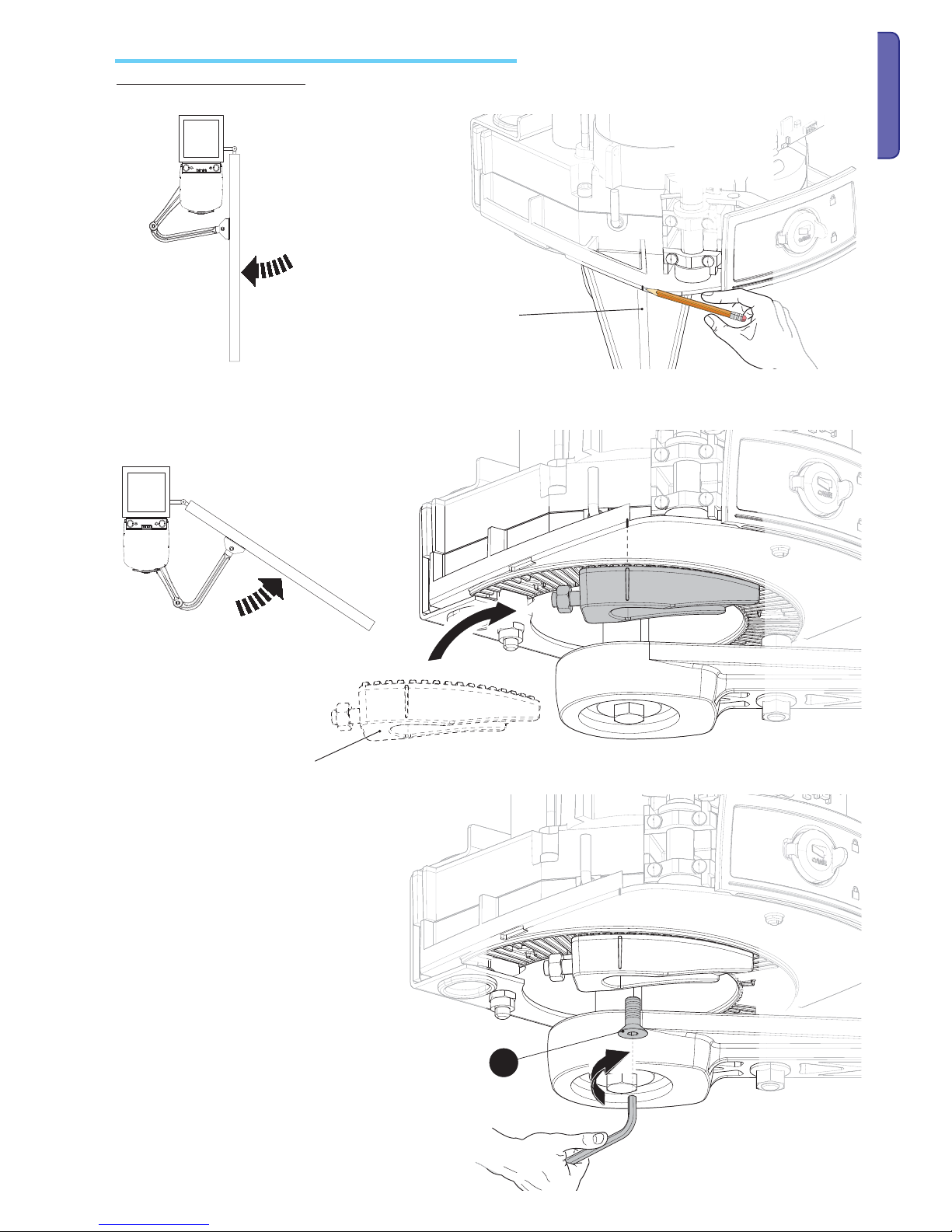
Before installing the operator, remove the gearmotor cover. Remove the cap protecting the release override hatch lock, fi t the key into the lock and turn it
(Π().
Open the ha
tch and turn the screw that fastens the cover to the gearmotor (Ž ().
Lift the cover slightly from the sides ().
Remove the gearmotor fastening bracket ().
F
asten the brackets with suitable screws. Insert the rubber shim into the post fastening bracket.
Page 10

d
e
a
b
f
g
h
f
g
i
h
c
p.
10
10 - Manual code:
119 DW 02
119 DW0 2 ver.
2. 0
2. 0 06/2012 © CAME Cancelli Automatici S.p.A. - The data and information in this manual may be changed at any time and without obligation on the part of Came Cancelli Automatici S.p.A . to notify said changes.
ENGLISH
Fit plug into the gearmotor shaft hole. Fasten the transmission arm to the shaft with slow-shaft washer and the bolt .
Fasten the drive arm to the transmission arm with the pin, bolt and washer ().
Release the gearmotor (see paragraph manual release override and block of the gearmotor), fasten the drive arm to the gate bracket as shown in the
drawing().
Set up the required electrical cables threading them through the cable glands and blocking them to the gate post fastening U bracket. Insert the
gearmotor into the bracket and fasten it with nuts and bolts ( ).
Installing the gearmotor and transmission arms
Page 11
j
p.
11
11 - Manual code:
119 DW 02
119 DW0 2 ver.
2. 0
2.0 06/2012
© CAME Cancelli Automatici S.p.A . - The data and information in this manual may be changed at any time and without obligation on the part of Came Cancelli Automatici S.p.A. to notify said changes.
ENGLISH
Mounting the mechanical endstops (if no mechanical strike plates are included)
Manually close the leaf. Insert the mechanical stop as shown. The mark on the case must match the groove on the stop.
Fasten the stop using the bolt .
Mechanical endstop
Centre of the arm
For the opening mechanical endstops .
With the gearmotor released, completely open the leaf, manually. Mark the case near the centre of the arm.
Page 12

j
p.
12
12 - Manual code:
119 DW 02
119 DW0 2 ver.
2. 0
2. 0 06/2012 © CAME Cancelli Automatici S.p.A. - The data and information in this manual may be changed at any time and without obligation on the part of Came Cancelli Automatici S.p.A . to notify said changes.
ENGLISH
Manually open leaf. Insert the mechanical stop as shown. The mark on the case must match the groove on the stop.
Fasten the stop using the bolt .
Mechanical endstop
Centre of the arm
For the closing mechanical endstops .
With the gearmotor released, completely open the leaf, manually. Mark the case near the centre of the arm.
Page 13

-
+
-
+
-
+
-
+
p.
13
13 - Manual code:
119 DW 02
119 DW0 2 ver.
2. 0
2.0 06/2012
© CAME Cancelli Automatici S.p.A . - The data and information in this manual may be changed at any time and without obligation on the part of Came Cancelli Automatici S.p.A. to notify said changes.
ENGLISH
Adjusting the limit switches
In the same way, adjust the opening limit-switch by turning the grub screw of the other stop (see drawing).
Adjusting the closing and opening endstop points of left-side gearmotors (internal view).
With the gearmotor released and the gate leaf closed, adjust the closing limit-switch grub screw by turning it either clockwise or anti clockwise. Fasten
the grub screw using the nut (see drawing).
Page 14

-
+
-
+
-
+
-
+
p.
14
14 - Manual code:
119 DW 02
119 DW0 2 ver.
2. 0
2. 0 06/2012 © CAME Cancelli Automatici S.p.A. - The data and information in this manual may be changed at any time and without obligation on the part of Came Cancelli Automatici S.p.A . to notify said changes.
ENGLISH
In the same way, adjust the opening limit-switch by turning the grub screw of the other stop (see drawing).
Adjusting the opening and closing endstop points of the right-side gearmotor (internal view).
With the gearmotor released and the gate leaf closed, adjust the closing limit-switch grub screw by turning it either clockwise or anti clockwise. Fasten
the grub screw using the nut (see drawing).
Page 15

1
2
3
5
6
4
3
2
1
5
4
p.
15
15 - Manual code:
119 DW 02
119 DW0 2 ver.
2. 0
2.0 06/2012
© CAME Cancelli Automatici S.p.A . - The data and information in this manual may be changed at any time and without obligation on the part of Came Cancelli Automatici S.p.A. to notify said changes.
ENGLISH
RELEASE - Remove the protective cap from the lock Œ . Insert the trilobe key and turn it anticlockwise . Open the hatch and activate the release override lever Ž .
Manual release override and blocking of the gearmotor
BLOCK - Close the release override hatch . Insert the trilobe key and turn it clockwise . Insert the
protective cap
.
After making the electrical connections and necessary programming, fi
t the cover onto the gearmotor and fasten it . Close the hatch Ž, block the
gearmotor using the key and fi t the protective ca
p .
Note: when fi
tting the cover, be careful with the cable connecting the FA001 card to the electronic card.
Page 16

1
22
2
5
10
12
11
4
13
16
17
18
21
20
19
15
14
6
6
9
3
3
7
8
23
25
24
p.
16
16 - Manual code:
119 DW 02
119 DW0 2 ver.
2. 0
2. 0 06/2012 © CAME Cancelli Automatici S.p.A. - The data and information in this manual may be changed at any time and without obligation on the part of Came Cancelli Automatici S.p.A . to notify said changes.
ENGLISH
Description
Main component parts
Command and control electronics
The control panel should be powered by 230 V AC, at 50/60 Hz frequency.
the command devices and accessories are powered by 24 V. The accessories must not exceed 50 W overall.
All connections are protected by quick fuses, see table.
The functions on the entry and exit contacts, the time settings and user management, are all set and viewable on the display which is managed by the
software.
Warning! Before acting on the control panel, cut off
the power supply.
1 Transformer
2 V power supply terminals
3 Transformer terminals
4 Gearmotor terminals
5 Command and safety device terminals
6) Encoder terminals
7 Terminals for transponder-based devices
8 Keypad selector terminals
9 Antenna terminals
10 Electro-lock fuse
11 -Accessories fuse
12 Board fuse
13 Line fuse
14 power on voltage present LED warning light
15 Programming indicator LED
16 Display
17 Programming buttons
18 FA001 board connector
19 Memory roll card connector
20 700 R800 or R800 card connector
21 AF card connector
22 FA001 board
23 4 Connector for connecting to the ZF4 card
24 001 Terminals for connecting the second FA001 card
25 25 LED to signal gate status
FUSE TABLE
Line fuse
5 A-F
Accessories fuse
1.6 A-F
Control unit fuse 630 mA-F
Electro-lock fuse 3.15 A-F
Page 17

p.
17
17 - Manual code:
119 DW 02
119 DW0 2 ver.
2. 0
2.0 06/2012
© CAME Cancelli Automatici S.p.A . - The data and information in this manual may be changed at any time and without obligation on the part of Came Cancelli Automatici S.p.A. to notify said changes.
ENGLISH
LED signal light
- QUICK switching-on
of th
e blue LEDs UPWARDS, signals the
leaves are opening.
- SLOW switching-on of
blue LEDs - UPWARDS,
signals that the leaves
are in opening slow
down.
- Red flashing LEDs 1
and 2, signal encoder
malfunction, call for
assistance.
- Red flashing LEDs 1, 2,
3 and 4, signal that the
normally closed (N.C.)
contacts are open (e.g.
photocells, stop button).
- QUICK switching-on
of the blue LEDs DOWNWARDS, signals
that the leaves are
closing.
- SLOW switchingon of blue LEDs DOWNWARDS, signals
that the leaves are in
closing slow down.
- The CAME logo stays lit
always.
Page 18

24V 12V 0
U V W X Y E
L1T L2T CT
L N
10 11 ES
24V 12V 0
10 11 ES TS 1 2 3 3P 4 5 7 CX CY
U V W X Y E
L2T L1T
1 2 3 4
0 12 24
p.
18
18 - Manual code:
119 DW 02
119 DW0 2 ver.
2. 0
2. 0 06/2012 © CAME Cancelli Automatici S.p.A. - The data and information in this manual may be changed at any time and without obligation on the part of Came Cancelli Automatici S.p.A . to notify said changes.
ENGLISH
Electrical connections
Power supplies
Terminals for powering the
24V A
C accessories
Overall allowed power: 50 W
Power supply at 230
V AC, Frequency 50 /
60 Hz
12 V - 15 W max. Electro-lock
FA001 board. Signals the gate movement
and slow down phases, see signal LED light
paragraph.
Gate open warning light (Contact rated for: 24 V - 3 W
Max.). Signals gate status, see feature F 10.
Movement Flasher (contact rated for: 230 V - 25
W Max.). Flashes while
gate opens and closes.
Warning devices
Cycle or courtesy lamp (contact rated for: 230 V - 25 W Max).
Aux
iliary connection to freely position outdoor lamp, to enhance lighting when parking or driving off.
Cycle: it stays lit from the moment the lead starts opening until it is completely closed
(including the automatic closing time).
Courtesy: stays lit for a set time of 180 seconds.
Tra nsfor mer
Black
Red
White
Orange
Purple
Blue
Page 19

CANCELLI AUTOMATICI
R700
CANCELLI AUTOMATICI
R800
10 11 ES TS 1 2 3 3P 4 5 7 CX CY
+ENC1-
+ENC2-
S1 GND
A B
AF
CAME
ACCESS CONTROL
p.
19
19 - Manual code:
119 DW 02
119 DW0 2 ver.
2. 0
2.0 06/2012
© CAME Cancelli Automatici S.p.A . - The data and information in this manual may be changed at any time and without obligation on the part of Came Cancelli Automatici S.p.A. to notify said changes.
ENGLISH
Command devices
Stop button (N.C. contact.). Gate stop button that excludes the automatic
closing cycle, to resume movement press the command button or use
another command device.
N.B.: if contact is unused, select 0 (Deactivated) from the F 1
function.
Opening device (N.O. contact)
Command device (N.O. contact). Commands for opening
and closing the gate, see feature F 7.
Device for partial or pedestrian opening (N.O. contact).
Command for opening a leaf for pedestrian passages.
Closing device (N.O. contact)
N.B.: plug in the (R700) coding card
for the (TSP00) sensor or the (LT001)
card reader to be recognised.
Antenna with RG58 cable for
remote controls.
N.B.: insert the R800
decoding board to have
the S6000/S7000 keypad
selector recognised.
AF remote control card.
Red
Black
White
Blue
(N.O.) contact. for command device
(Transponder or card reader with
R700 board).
(N.O.) contact. for command
device (keypad selector with
R800 board).
Page 20

U V W X Y E
+ ENC1 - + ENC2 -
FA40230FA40230CB
U V W X Y E
+ ENC1 - + ENC2 -
FA40230FA40230CB
FA40230CBFA40230
FA40230CBFA40230
U V W X Y E
+ ENC1 - + ENC2 -
U V W X Y E
+ ENC1 - + ENC2 -
FA40230CB
p.
20
20 - Manual code:
119 DW 02
119 DW0 2 ver.
2. 0
2. 0 06/2012 © CAME Cancelli Automatici S.p.A. - The data and information in this manual may be changed at any time and without obligation on the part of Came Cancelli Automatici S.p.A . to notify said changes.
ENGLISH
Gearmotor with encoder
Encoder wire colours:
+ = Wh
ite
ENC = Brown
- = green
Encoder wire colours:
+ = White
ENC = Brown
- = green
Default setting for electrical connections:
operator installed on the left and gearmotor
installed on the right (internal vie
w) with operator
closing delay.
Electrical connections:
gearmotor installed on the left and operator
installed on the right (internal view) with operator
closing delay.
Default setting for electrical connections:
operator installed on left side (internal view)
Electrical connections:
operator installed on right side (internal view)
Page 21

10 11 ES TS 1 2 3 3P 4 5 7 CX CY
S 1 2 3 3P 4 5 7 CX CY
DF
10 11 ES TS 1 2 3 3P 4 5 7 CX CY
10 11 ES TS 1 2 3 3P 4 5 7 CX CY
RX TX
./ # .#
RX TX
p.
21
21 - Manual code:
119 DW 02
119 DW0 2 ver.
2. 0
2.0 06/2012
© CAME Cancelli Automatici S.p.A . - The data and information in this manual may be changed at any time and without obligation on the part of Came Cancelli Automatici S.p.A. to notify said changes.
ENGLISH
DF with control card for DFI
connections
Confi gure contact CX or CY (N.C.), input for sensitivesafety-edge type devices, that are EN 12978 standards
compliant. See CX input functions (Function F2) or CY
(Function 3) in:
- C7 reopening when closing, while the gate is closing,
opening the contact will invert movement until it is
completely opened;
-C8 reclosing when opening, while the gate is opening,
opening the contact will invert movement until it is
completely closed.
N.B.: if contacts CX and CY are unused, they should
be deactivated when programming.
Photocells
Confi gure contact CX or CY (N.C.), input for
safety devices such as photocells, compliant with EN 12978
standards.
See CX input functions (Function F2) or CY (Function 3) in:
- C1 reopening when closing, while the gate is closing, opening
the contact will invert movement until it is completely opened;
- C2 reclosing when opening, when leaves are opening,
opening the contact will trigger inversion of movement until
completely closed;
- C3 partial stop, leaves stop if moving with consequent
triggering of automatic closing (if automatic closing feature
is inserted);
- , obstacle stand-by , stops the leaves if they are moving and
resumes movement after obstacle is removed.
N.B.: if contacts CX and CY are unused, they should be deactivated when programming.
Photocells
DIR
Photocells
DELTA-S
Photocells
DELTA
Sensitive safety edges
Page 22

10 11 ES TS 1 2 3 3P 4 5 7 CX CY
10 11 ES TS 1 2 3 3P 4 5 7 CX CY
./
.#
#
&53)"),%M!
48
48
48
#
.#
DELTA
DIR / DELTA S
24V 12V 0
U V W X Y E
L1T L2T CT
L N
10 11
L2T L1T
1 2 3 4
0 12 24
p.
22
22 - Manual code:
119 DW 02
119 DW0 2 ver.
2. 0
2. 0 06/2012 © CAME Cancelli Automatici S.p.A. - The data and information in this manual may be changed at any time and without obligation on the part of Came Cancelli Automatici S.p.A . to notify said changes.
ENGLISH
With each opening and closing command, the card checks the e ciency of the safety devices (i.e. photocells). Any anomalies in the working of the
photocells is fl agged on the electrical card, and this cancels any commands from the radio transmitters or buttons.
Electrical connection to work the photocells safety test:
- the transmitter and receiver, must connected as shown in the diagram:
- select from the F5 feature which inputs the test should be activated on.
Electrical connection for operating the photocell's safety test
Settings and adjustments
To vary the motor torque, move the faston shown to
one of the four positions; 1 min ÷ 4 max.
Page 23

CANCELLI AUTOMATICI
R700
ACCESS CONTROL
TOP
TSP00LT001
CAME
TAM
ATOMO
TWIN
TOUCH
CANCELLI AUTOMATICI
R800
S7000
24V 12V 0
U V W X Y E
L1T L2T CT
L N
10 11 ES TS 1 2 3 3P 4 5 7 CX CY
+ENC1-
+ENC2-
S1 GND
A B
AF
S6000
ESC < > ENTER
F I
p.
23
23 - Manual code:
119 DW 02
119 DW0 2 ver.
2. 0
2.0 06/2012
© CAME Cancelli Automatici S.p.A . - The data and information in this manual may be changed at any time and without obligation on the part of Came Cancelli Automatici S.p.A. to notify said changes.
ENGLISH
Programming
Memorising data
Description of programming commands
To register, edit or remove users or command the operator via radio transmitter, plug in the AF43S card.
If using either the transponder of card reader, fit the R700 board or, alternatively, the R800 keypad selector board.
Fit the memory roll to save and load registered users onto another board.
{
{
The ENTER button is for:
- accessing the menus;
- confirm and memorise the set value.
The ESC button is for:
- exiting menus;
- cancelling any changes.
The <> keys are for:
moving from one menu item to another;
- increasing or decreasing values.
Display
Memory roll
AF card
R700 card
R800 board
{
Page 24

p.
24
24 - Manual code:
119 DW 02
119 DW0 2 ver.
2. 0
2. 0 06/2012 © CAME Cancelli Automatici S.p.A. - The data and information in this manual may be changed at any time and without obligation on the part of Came Cancelli Automatici S.p.A . to notify said changes.
ENGLISH
Menu map
F 1 Total stop feature (1-2)
F 2 Function associated to CX input
F 3 Function associated to CY input
F 5 Safety test function
F 6 Maintained action function
F 7 Command mode on 2-7
F 8 Command mode on 2-3
F 9 Obstacle detection when motor is idle function
F 10 Indicator light function
F - 11 Excluding encoder
F 14 Sensor-type selection feature
F 16 Recoil function
F 18 Supplementary light feature
F 19 Automatic closing time
F 20 Automatic closing time after partial opening;
F 21 Pre-flashing time
F 22 Working time
F 23 Delay time when closing
F 24 Delay time when closing
F 30 Adjusting motor slow down speed
F 34 Sensitivity during movement
F 35 Sensitivity during deceleration
F 36 Adjusting open-partially
F 37 Adjusting the motor's starting point of slow down when opening
F 38 Adjusting the motor's starting point of slow down when closing
F 39 Adjusting the motor's end-strike starting point when opening
F 40 Adjusting the motor's end-strike starting point when closing
F 46 Setting the number of motors
F 50 Saving date in the memory roll
F 51 Reading memory roll data
F 59 Enabling CAME logo feature
U 1 Registering new users with associated command
U 2 Cancelling one user
U 3 Completely cancel users
A 2 Motor test
A 3 Calibrating travel
A 4 Reset parameters
H 1 Software version
Page 25

F
i
A2
0
i
ENTER
>
>
ENTER
>...>
F
i
A4
0
ENTER
>
>
ENTER
>...>
i
F
i
A3
0
i
ENTER
>
>
ENTER
>...>
p.
25
25 - Manual code:
119 DW 02
119 DW0 2 ver.
2. 0
2.0 06/2012
© CAME Cancelli Automatici S.p.A . - The data and information in this manual may be changed at any time and without obligation on the part of Came Cancelli Automatici S.p.A. to notify said changes.
ENGLISH
A 2 (Motor test): test activation to check for proper rotation direction of the gearmotor (see the paragraph about motor test).
0 = deactivated; 1 = activated.
Confirm with the ENTER button after choosing the value for each feature.
Motor test and calibrarion menu
Important! We suggest starting the programming by first doing the following:
1 Motor test;
2 Calibration of travel.
A 4 (Reset parameters): data restoring procedure (for default settings) and travel calibration cancellation.
0 = deact
ivated; 1 = activated.
A 3 (travel calibration): automatic gate-travel calibration operation (see the paragraph about calibrating travel).
0 = deact
ivated; 1 = activated.
Warning! If needed, you can restore the factory settings with the following feature:
Page 26

F
i
0
i
ENTER
ENTER >
>
F
i
0
F
2
8
F
i
0
F
5
F
i
0
3
F
3
2
4
4
i
i
i
2
2
3
3
ENTER >
>
>
>
>
>
>
>
ENTER > > >
>
>
>
>
ENTER
>
>
>
>
ENTER
ENTER
ENTER
8
7
7
>...>
>...>
F
i
0
F
6
i
ENTER > > ENTER
>...>
p.
26
26 - Manual code:
119 DW 02
119 DW0 2 ver.
2. 0
2. 0 06/2012 © CAME Cancelli Automatici S.p.A. - The data and information in this manual may be changed at any time and without obligation on the part of Came Cancelli Automatici S.p.A . to notify said changes.
ENGLISH
Features menu
F 1 (Total Stop 1-2) - N.C. input: gate stop with consequent exclusion of possible automatic closing cycle; to restore movement act on the command
devic
e. Insert safety device on [1-C2]; if unused, select function "0.
= 0 = Deactivated (default); 1 = activated
F 2 (2-CX input): NC safety contact with possibility to associate the following functions: C1 (reopen when closing), (reclose when opening), C3 (par
tial
stop;), C4 (obstacle stand-by), C7 (reopen when closing, for sensitive safety edges), (reclose when opening, for sensitive safety edges) or deactivated,
see safety devices in electrical connections.
= 0 = Deactivated (default); 1 = C1; 2 = C2; 3 = C3; 4 = C4; 7 = C7; 8 = C8.
F 3 (2-CY input): NC safety contact with possibility to associate the following functions: C1 (reopen when closing), (reclose when opening), C3 (par
tial
stop;), C4 (obstacle stand-by), C7 (reopen when closing, for sensitive safety edges), (reclose when opening, for sensitive safety edges) or deactivated,
see safety devices in electrical connections.
= 0 = Deactivated (default); 1 = C1; 2 = C2; 3 = C3; 4 = C4; 7 = C7; 8 = C8.
F 5 (Safety test): allows the card to check the efficiency of safety devices (i.e. photocells) after every opening or closing command.
= 0 = Deac
tivated (default); 1 = CX; 2 = CY; 3 = CX+CY
F 6 (Maintained action): the gate works by keeping the button pressed (a 2-3 button for opening, a 2-4 button for closing). This excludes all of the
other c
ommand devices including the radio command.
0 = Deactivated (default); 1 = activated.
Page 27

F
i
0
F
7
i
ENTER > > ENTER
>...>
F
i
0
F
8
F
i
0
F
9
i
i
ENTER >
>
ENTER
ENTER > > ENTER
>...>
>...>
F
i
0
F0 i
i
ENTER > > ENTER
>...>
F i i
F
i
0
i
ENTER
>...>
> > ENTER
F
i
0
i
ENTER > > ENTER
F4 i
>...>
F
i
0
i
ENTER > > ENTER
F6 i
>...>
p.
27
27 - Manual code:
119 DW 02
119 DW0 2 ver.
2. 0
2.0 06/2012
© CAME Cancelli Automatici S.p.A . - The data and information in this manual may be changed at any time and without obligation on the part of Came Cancelli Automatici S.p.A. to notify said changes.
ENGLISH
F 7 (Command 2-7): setting the 2-7 contact to either the step (open-close) or sequential (open-stop-close-stop) modes.
0 = step-step (default); 1 = sequential.
F 8 (Command 2-3P): setting contact on 2-3P to pedestrian opening (total opening of the second leaf) or partial (partial opening of the second leaf
depending on p
ercentage setting between 10 and 80 of the travel, feature F 36).
0 = pedestrian opening (default); 1 = Partial opening.
F 9 (Obstacle detection): with motor idle (gate closed, open or after a total stop command), it prevents any movement if the safety devices (e.g.
photo
cells) detect an obstacle.
0 = Deactivated (default); 1 = activated.
1 = - 1 = - gate is opening, it flashes intermittently each half-second;
- gate closing, it flashes intermittently each second;
- gate open, stays lit;
- gate closed, stays off.
F 11 (Encoder exclusion): excludes management of the slow downs, obstacle detection and sensitivity.
0 = E
ncoder activated. (default); 1 = Encoder deactivated.
F 10 (Open signal-light): Light bulb connected to 10-5, signals gate status.
F 14 (Sensor type): setting the sensor-type for the operator command via TSP00 transponder or LT001 magnetic card reader with the R700 coding
board or S70
00 keypad with R800 coding board.
0TAG; 1 = S7000 (default).
F 16 (Ramming): before each opening and closing manoeuvre, the leaves press against the strike-plate for a few seconds to facilitate the electro-lo
ck
release (to adjust the time, see feature F26).
0 = deactivated (default); 1 = activated.
0 = gate open or moving, stays lit (default)
Page 28

F
i
ENTER
> >
ENTER
> >
>...>
0
0 I
i
F i2
F
i
ENTER
> >
ENTER
> >
>...>
i
F02 I08
2
F
i
ENTER
>
>
ENTER
>
>
>...>
F9 i
0
i
I08
F
i
ENTER
> >
ENTER
> >
>...>
F22
I02
5
6
F
i
ENTER
> >
ENTER
> >
>...>
F32
0
0 I
i
F
i
0
F8 i
i
2
ENTER > > ENTER
>
>...>
p.
28
28 - Manual code:
119 DW 02
119 DW0 2 ver.
2. 0
2. 0 06/2012 © CAME Cancelli Automatici S.p.A. - The data and information in this manual may be changed at any time and without obligation on the part of Came Cancelli Automatici S.p.A . to notify said changes.
ENGLISH
F 19 (Automatic closing time): The automatic closing timer activates at the closing endpoint. The pre-set time is adjustable, and is anyhow conditio-
ned by a possible intervention by the safety devices and is deactivated after a total emergency stop or when the power is cut.
The waiting time can be deactivated or adjusted from 1" to 180".
= 0 = Deactivated (default); 1 = 1 second; 2 = 2=seconds; .................. 180 = 180=seconds.
F 20 (Automatic closing time after partial or pedestrian opening): leaf automatic closing time after a partial or pedestrian opening command.
The d
oor closes automatically once this time-frame has elapsed and is anyway subject to the trigger of any safety devices and it deactivates after a
«total emergency stop" or due to power outages . The waiting time can be adjusted from 1" to 180”
Note: the automatic closing time (see F 19) should not be deactivated.
1 = 1 second; 2 = 2=seconds; .................. 5 = 5=seconds (default); .................. 180 = 180=seconds.
F 21 (Pre-flashing time): after an opening or closing command, the flashing light connected on (10-E), flashes for an adjustable time interval before
the mano
euvre begins.
the pre-flashing time can be deactivated or adjusted from 1" to 10".
= 0 = Deactivated (default); 1 = 1 second; 2 = 2=seconds; .................. 10 = 10=seconds.
F 22 (Working time): motor operation time in when opening or closing.
the wo
rking time can be adjusted to between 5" and 120"
5 = 5=(seconds; .................. 120 = 120=(seconds (default).
F 23- (Opening delay time): after an opening command, the leaf of gearmotor (M1) starts moving after that of gearmotor (M2) and the time is adju-
stabl
e.
the delay time can be deactivated or adjusted from 1" to 10".
= 0 = Deactivated (default); 1 = 1 second; 2 = 2=(seconds .................. 10 = 10=seconds.
F 18 (Light W-E): output on contact W-E for the light with the following feature:
- movement war
ning flashing light, flashes while gate is opening and closing.
- outdoor freely placeable light, to enhace lighting in the parking area, set as courtesy light which stays lit for a set time of 180 seconds or as a cycle
light that stays on from the moment the leaf starts opening until it is completely closed (including automatic closing time) .
0 = Flashing light (by default); 1 = Cycle; 2 = Courtesy.
Page 29

F
i
ENTER
> >
ENTER
> >
>...>
0
i
F42
52
F
i
F03
ENTER
> >
ENTER
>
>
>...>
F
i
I00
0 I
I I
ENTER
> >
ENTER
>
>
>...>
F43
F
i
I00
0 I
I I
ENTER
> >
ENTER
>
>
>...>
F53
F
i
0 I
I I
ENTER
> >
ENTER
>
>
>...>
F63
08
F
i
0 I
I I
ENTER
> >
ENTER
>
>
>...>
F73
06
0
i
3
2
p.
29
29 - Manual code:
119 DW 02
119 DW0 2 ver.
2. 0
2.0 06/2012
© CAME Cancelli Automatici S.p.A . - The data and information in this manual may be changed at any time and without obligation on the part of Came Cancelli Automatici S.p.A. to notify said changes.
ENGLISH
F 24 (Closing delay time): after a closing command or after automatic closing, the M2 gearmotor lead delays its start compared to gearmotor
M1; the time is adjustable.
the delay time can be deactivated or adjusted from 1" to 25".
= 0 = Deactivated (default); 1 = 1 second; 2 = 2=(seconds .................. 25 = 25=seconds.
F 30 (Slow down speed): setting the time during motor slow downs.
= 0 = Deac
tivated; 1 = maximum speed; 2 = intermediate speed 3 = minimum speed.
F 34 (travel sensitivity): adjusts the obstacle-detection sensitivity during travel.
10 = maximum sensitivity; .................. 100 = minimum sensitivity (default).
F 35 (Deceleration sensitivity): adjusts the obstacle detection sensitivity when decelerating.
10 =
maximum sensitivity; .................. 100 = minimum sensitivity (default).
F 36 (Adjusting partial opening): adjusts the leaf opening of the second motor M2 as a percentage of the total travel
10 = 10% of the travel (default); .................. 80 = 80% of the run-cycle.
F 37 (Opening slow down point): adjusts the motor's beginning slow down point before the opening endstop.
T
he b
eginning slow down point is calculated as a percentage of the leaf's complete travel (see par. about illustrating the slow down and end-strike
areas and points)
10 = 10% of the travel; .................. 25 = 25% of the run-cycle (default); .................. 60 = 60% of the run-cycle.
Page 30

F
i
F93
0 I
i
2
F
i
0 I
I I
ENTER
> >
ENTER
>
>
>...>
F83
06
ENTER
> >
ENTER
>
>
>...>
F
i
F04
0 I
i
2
ENTER
> >
ENTER
>
>
>...>
F
i
0
F64
i
ENTER > > ENTER
>...>
F
i
0
F05
i
ENTER > > ENTER
>...>
F
i
0
F i5
i
ENTER > > ENTER
>...>
p.
3 0
3 0 - M anual code:
119 DW 02
119 DW0 2 ver.
2. 0
2. 0 06/2012 © CAME Cancelli Automatici S.p.A. - The data and information in this manual may be changed at any time and without obligation on the part of Came Cancelli Automatici S.p.A . to notify said changes.
ENGLISH
F 38 (Closing slow down point): adjusts the motor's beginning slow down point before the closing endstop.
the beginning deceleration point is calculated as a percentage of the leaf's complete travel (see par. illustration of slow down and end strike areas and
points )
10 = 10% of the travel; .................. 25 = 25% of the run-cycle (default); .................. 60 = 60% of the run-cycle.
F 39 (Opening end-strike point): adjusts the starting point of the motor's end-strike before the opening endstop.
the b
eginning end-strike point is calculated as a percentage of the leaf's complete travel. (see par. illustration of slow down and end strike areas and
points )
1 = 1% of the travel; .................. 5 = 5% of the run-cycle (default); ..................10 = 10% of the run-cycle.
F 40 (Closing end-strike point): adjusts the starting point of the motor's end-strike before the closing endstop.
the b
eginning end-strike point is calculated as a percentage of the leaf's complete travel (see par. illustration of slow down and end strike areas and
points )
1 = 1% of the travel; .................. 5 = 5% of the run-cycle (default); .................. 10 = 10% of the run-cycle.
F 46 (Number of motors): setting the number of motors connected to the control panel.
0 = Ena
bling both motors (M1+M2) (default); 1 = 2 = Enabling just one motor (M2)
F 50 (Save data): saves users and all settings in the memory roll.
Not
e: this feature appears only if the memory roll is plugged into the mother board.
= 0 = Deactivated; 1 = activated
F 51 (Data reading): loads memory roll data onto the mother board.
Not
e: this feature appears only if the memory roll is plugged into the mother board.
= 0 = Deactivated; 1 = activated.
Page 31

5
F
i
3
i
2
4
ENTER > > ENTER
>...>
u i
>
> >
F
i
>...>
ENTER
ENTER
> >
>
>
52
i
2
u2
F
i
0
u3
i
ENTER > > ENTER
>...>
F
i
H I
0i.
ENTER
ENTER
>...>
0 I
F
i
0
F95
i
ENTER > > ENTER
>...>
>
> >
I08
p.
31
31 - Manual code:
119 DW 02
119 DW0 2 ver.
2. 0
2.0 06/2012
© CAME Cancelli Automatici S.p.A . - The data and information in this manual may be changed at any time and without obligation on the part of Came Cancelli Automatici S.p.A. to notify said changes.
ENGLISH
U 1 (Adding user with associated command): registering users (max 25 users) associated to a command, via transmitter (see paragraph about
registering users with associated command).
1 = 1 = step-step command (open-close); 2 = 2 = 2 = sequential command (open-stop-close-stop); 3 = open only command; 4 = 8 = partial/pede-
strian command (see feature F8); 5 = B1-B2 output.
U 2 (Cancelling users): cancelling one user (see paragraph on cancelling one user)
U 3 (Cancelling users): cancelling all users on memory. Press Enter button to confirm cancellation
0 = Deac
tivated; 1 = 1 = Cancelling all users
H 1 (Version): view software version.
Users menu
Info menu
F 59 (Enabling the CAME logo ): enables switching on or off of the CAME logo of after the gate is completely closed, it stays on for a time that can be
adjust
ed to between10” and 180”.
= 0 = Deactivated; 1 = Activated (default); 10 = 10 seconds................. 11 = 11=(seconds .................. 180 = 180=seconds..
Page 32

ESC < > ENTER
I
U
ESC < > ENTER
2
<
<
> EN
>
>
ESC < > ENTER
8
ESC < > ENTER
2
2
ESC < > ENTER
2
U
<
<
> ENTE
EN >
>
ESC < > ENTER
C
L
p.
32
32 - Manual code:
119 DW 02
119 DW0 2 ver.
2. 0
2. 0 06/2012 © CAME Cancelli Automatici S.p.A. - The data and information in this manual may be changed at any time and without obligation on the part of Came Cancelli Automatici S.p.A . to notify said changes.
ENGLISH
Select U 1.
Press ENTER to confirm.
Important! Before entering users, remove the memory roll card if present.
... an available number between 1 and 25 will
fla
sh for a few seconds, this number will be
assigned to the user after the code is sent via
transmitter or other such command device).
User Associated com-
mand
12 3 4 5 6 7 8 9 10 11 12 13 14 15 16 17 18 19 20 21 22 23 24 25 -
Adding user with associated command
Select U 2.
Pre
ss ENTER to confirm.
2) Use the arrow buttons to select the user number you wish to cancel.
Press ENTER to confirm...
... CLr will be displayed to confirm cancellation.
Cancelling one user
Select a command to associate to the user.
The commands are:
- step-step (open-close) = 1
- sequential (open-stop-close-stop) = 2;
- open = 3;
- partial opening/pedestrian = 4.
Press ENTER to confirm...
N.B.: during registering / cancelling new users operations, the fl ashing numbers viewed, are available and usable for any user needing to be r
egistered (
maximum 25 users).
Page 33

ESC < > ENTER
I
ESC < > ENTER
2
a
>
>
ESC < > ENTER
---
M2M1
ESC < > ENTER
oP2
M2M1
ESC < > ENTER
oP I
p.
33
33 - Manual code:
119 DW 02
119 DW0 2 ver.
2. 0
2.0 06/2012
© CAME Cancelli Automatici S.p.A . - The data and information in this manual may be changed at any time and without obligation on the part of Came Cancelli Automatici S.p.A. to notify said changes.
ENGLISH
Select A 2.
Press ENTER to confirm.
1) Select 1 to activate the test.
Press ENTER to confirm...
... 3) ..."---" will appear on the screen, waiting for
a command...
Keep the > button pressed and check that the
leaf of the second gearmotor M2 opens completely .
Note: if the leaf closes, invert the motor phases.
Do the same procedure with the < arrow button
to check the leaf of the first gearmotor M1.
Note: if the leaf closes, invert the motor phases.
Motor test
Page 34

ESC < > ENTER
a3
ESC < > ENTER
i
<
<
> EN
>
>
ESC < > ENTER
cl i
ESC < > ENTER
cl2
ESC < > ENTER
op2
ESC < > ENTER
op I
M2
M1
M2
M1
M2
M1
M2
M1
p.
34
34 - Manual code:
119 DW 02
119 DW0 2 ver.
2. 0
2. 0 06/2012 © CAME Cancelli Automatici S.p.A. - The data and information in this manual may be changed at any time and without obligation on the part of Came Cancelli Automatici S.p.A . to notify said changes.
ENGLISH
Select A 3.
Press ENTER to confirm.
1) Select 1 and press ENTER to confirm the
automatic-calibration-of-travel mode...
The leaf of the first motor will perform a closing
manoeuvre until it reaches the strike plate.
...consequently, the leaf of the second motor will
perform the same manoeuvre...
...then the second motor's leaf, will open completely until the end-strike...
... the leaf of the first motor will perform the same
manoeuvre.
N.B.: before calibrating the travel, check that the manoeuvring area is free of any obstacles and check for the presence of any mechanical
opening and closing strik
e-plates.
Important! While calibrating, all safety devices will be deactivated until calibration is complete, except for the TOTAL STOP.
Calibrating travel
Page 35

p.
3 5
35 - Manual code:
119 DW 02
119 DW0 2 ver.
2. 0
2.0 06/2012
© CAME Cancelli Automatici S.p.A . - The data and information in this manual may be changed at any time and without obligation on the part of Came Cancelli Automatici S.p.A. to notify said changes.
ENGLISH
This product is only intended to be used for the purpose it was designed. Any other use is therefore
improper and dangerous. The manufacturer is not liable for any damage caused by improper, wrongful
or unreasonable use.
Stay away from working mechanical parts. Stay out of the working range of the moving operator.
Do not oppose the movement of the operator as this may result in danger.
Do not allow children to play to loiter within the working range of the operator. Keep transmitters and any other command devices away from children,
to prevent the operator from being activated by mistake.
Immediately stop using the operator if any anomaly is manifested.
Danger high voltage Transit forbidden during opera-
tion
Important general safety instructions
Safety instructions
Error messages
Er1: calibration of motor M1 interrupted; check proper connection and operation of motor M1.
Er2: calibration of motor M2 interrupted; check proper connection and operation of motor M2.
Er3: encoder out-of-order; call for assistance.
Er4: services test error: check proper connections and functioning state of the safety devices.
Er5: insu cient working time; check the set time, it could be insu cient to complete a full cycle.
Er6: maximum number of detected obstacles
C0: contact 1-2 (stop) unused and not deactivated
C1/2/3/4/7/8: unused and not deactivated CX and/or CY contacts
RED fl ashing LED: command board still not calibrated to the travel.
Periodic servicing performed by end-user includes: cleaning the photocells' glass, checking the proper working state of the safety devices and making sure the operator is free of any impediments.
We also recommend to periodically check the lubrication the tightness of the bolts and screws on the operator.
To check that the safety devices are working properly, wave an object in front of the photocells during closing; if the operator inverts its direction of
travel or blocks movement, then the photocells are working properly. This is the only maintenance job that should be done with the power source on.
Before doing any maintenance or repair job, cut off the main power, to prevent any dangerous situations.
To wipe clean the photocell glass, use a slightly damp cloth, and do not use any solvents or other chemical products that may ruin the device.
Check that there is not vegetation within range of the photocells, and that no objects interfere with the operation of the automated device.
Maintenance
Periodic maintenance
Danger of hand crushing
Page 36

p.
3 6
3 6 - M anual code:
119 DW 02
119 DW0 2 ver.
2. 0
2. 0 06/2012 © CAME Cancelli Automatici S.p.A. - The data and information in this manual may be changed at any time and without obligation on the part of Came Cancelli Automatici S.p.A . to notify said changes.
ENGLISH
Periodic maintenance log to be done twice yearly by the end-users
Date Notes Signature
The following table is used to log extraordinary maintenance, repair and improvement jobs done by the specialised external firms.
N.B.:. All extraordinary maintenance jobs must be carried out by skilled technicians.
Extraordinary maintenance log
Installer's stamp Product name
Date of job
Technician's signature
Customer's signature
Job carried out
_________________________________________________________________________________________________
_____________________________________________________________________________________________________________
__________________________________________________________________________
Extraordinary maintenance
COn its premises, Cancelli Automatici S.p.A. implements a certified Environmental Management System in compliance with the UNI EN ISO
14001 standard to ensure environmental protection.
Please help us to safeguard the environment. At CAME we believe this to be one of the fundamentals of our market operations and development strategies. Just follow these short disposal instructions:
DISPOSING OF THE PACKAGING
The components of the packaging (i.e. cardboard, plastic, etc.) are solid urban waste and may be disposed of without much trouble, simply by separating
them for recycling.
Before proceeding it is always a good idea to check your local legislation on the matter.
DO NOT DISPOSE OF IN NATURE!
PRODUCT DISPOSAL
Our products are made up of various materials. The majority of these (aluminium, plastic, iron, electrical wires) is solid urban waste. These can be
disposed of at local solid waste management dumps or recycling plants.
Other components (i.e. electronic cards, transmitter batteries, etc. ) may contain hazardous substances.
These must therefore be handed over the specially authorised disposal firms.
Before proceeding it is always a good idea to check your local legislation on the matter.
DO NOT DISPOSE OF IN NATURE!
Dismantling and disposal
Installer's stamp Product name
Date of job
Technician's signature
Customer's signature
Job carried out
_________________________________________________________________________________________________
_____________________________________________________________________________________________________________
__________________________________________________________________________
Page 37

p.
37
37 - Manual code:
119 DW 02
119 DW0 2 ver.
2. 0
2.0 06/2012
© CAME Cancelli Automatici S.p.A . - The data and information in this manual may be changed at any time and without obligation on the part of Came Cancelli Automatici S.p.A. to notify said changes.
ENGLISH
CE Declaration
Page 38

CA ME
CA ME
Fra nce
France
S.a.
S.a. FRANCE
7, Rue Des Haras
Z.i. Des Hautes Patures
92737
Nante rre Cedex
Nanterre Cedex
(+33) 0 825 825 874
(+33) 1 46 13 05 00
GERMANY
CA ME Gmbh See feld
CAME Gmbh Seefeld
Akazienstrasse, 9
16356
Seefe ld
Seefeld Bei Berlin
(+49) 33 3988390
(+49) 33 39883985
CA ME Au tomatismes S. a.
CA ME Automatismes S.a. FRANCE
3, Rue Odette Jasse
13015
Marseille
Marseille
(+33) 0 825 825 874
(+33) 4 91 60 69 05
U.A.E.
CA ME Gulf Fze
CAME Gulf F ze
O ce No: S10122a2o210
P.O. Box 262853
Jebel Ali Free Zone -
Dubai
Dubai
(+971) 4 8860046
(+971) 4 8860048
CA ME Au tomatismos S. a.
CA ME Automatismos S.a. SPAIN
C/juan De Mariana, N. 17-local
28045
Madrid
Madrid
(+34) 91 52 85 009
(+34) 91 46 85 442
RUSSIA
CAME Rus
CAME Rus
Umc Rus L lc
Umc Rus Llc
Ul. Otradnaya D. 2b, Str. 2, o ce 219
127273,
Moscow
Moscow
(+7) 495 739 00 69
(+7) 495 739 00 69 (ext. 226)
CA ME Unit ed K ingdom Ltd.
CA ME United Kingdom Ltd. GREAT BRITAIN
Unit 3 Orchard Business Park
Town Street, Sandiacre
Nottingha m
Nottingham - Ng10 5bp
(+44) 115 9210430
(+44) 115 9210431
PORTUGAL
CA ME Po rtugal
CAME Portugal
Ucj Por tuga l Unipessoal Ld a
Ucj Portugal Unipessoal Lda
Rua Liebig, nº 23
2830-141
Barreir o
Barreiro
(+351) 21 207 39 67
(+351) 21 207 39 65
CA ME Grou p Benelux S.a.
CA ME Group Benelux S.a. BELGIUM
Zoning Ouest 7
7860
Le ssin es
Lessines
(+32) 68 333014
(+32) 68 338019
INDIA
CA ME India
CAME India
Aut omation Solutions P vt. Ltd
Automation Solutions Pvt. Ltd
A - 10, Green Park
110016 -
New Delhi
New Delhi
(+91) 11 64640255/256
(+91) 2678 3510
CA ME Am eric as A utomati on L lc
CA ME Americas Automation Llc U.S.A
11345 NW 122nd St.
Medley
Medley, FL 33178
(+1) 305 433 3307
(+1) 305 396 3331
ASIA
CA ME As ia Pacifi c
CAME A sia Pacific
60 Alexandra Terrace #09-09
Block C, The ComTech
118 502
Singapore
Singapore
(+65) 6275 0249
(+65) 6274 8426
CA ME Gmbh
CA ME Gmbh GERMANY
Kornwestheimer Str. 37
70825
Korntal
Korntal Munchingen Bei Stuttgart
(+49) 71 5037830
(+49) 71 50378383
CA ME Ca ncelli A uto matici S.p. a.
CA ME Cancelli Automatici S.p.a. ITALY
Via Martiri Della Libertà, 15
31030
Dosson Di Casier
Dosson Di Casier (Tv)
(+39) 0422 4940
(+39) 0422 4941
Informazioni Commerciali 800 848095
ITALY
CA ME Sud s.r.l.
CA ME Sud s.r.l.
Via F. Imparato, 198
Centro Mercato 2, Lotto A/7
80146
Napoli
Napoli
(+39) 081 7524455
(+39) 081 7529190
CA ME Service Italia S.r.l.
CA ME Service Italia S.r.l. ITALY
Via Della Pace, 28
31030
Dosson Di Casier
Dosson Di Casier (Tv)
(+39) 0422 383532
(+39) 0422 490044
Assiste nza Tecnica 800 295 830
Assistenza Tecnica 800 295830
ITALY
CA ME Glob al U tilities s.r.l .
CA ME Global Utilities s.r.l.
Via E. Fermi, 31
20060
Gessate
Gessate (Mi)
(+39) 02 95380366
(+39) 02 95380224
09_2011
www.came.com www.came.it
Eng li sh
Eng li sh - Manual code:
119 DW 02
119 DW0 2 ver.
2. 0
2. 0 06/2012 © CAME Cancelli Automatici S.p. A.
The data and information in this manual may be changed at any time and without obligation on the part of CAME Cancelli Automatici S .p.A. to notify said changes.
 Loading...