

Page 1
CANCELLI AUTOMATICI
AUTOMAZIONE ESTERNA A BRACCI SNODATI PER CANCELLI A BATTENTE
EXTERNAL AUTOMATION SYSTEM WITH ARTICULATED ARMS FOR HINGED GATES
AUTOMATISME EXTERIEUR A BRAS ARTICULES POUR PORTAILS A BATTANT
ÄUSSERE AUTOMATISMUS MIT GELENKIGEN ARMEN FÜR FLÜGELTOREN
AUTOMATIZACIÓN EXTERNA CON BRAZOS ARTICULADOS PARA PUERTAS CON BISAGRAS
SERIE FAST |
FAST SERIES
|
SÉRIE FAST |
BAUREIHE FAST
F7024
|
SERIE FAST
Documentazione
Tecnica
S99
rev. 0.2
4/2002
©
CAME
CANCELLI
AUTOMATICI
119DS99
45 6 7 7
1
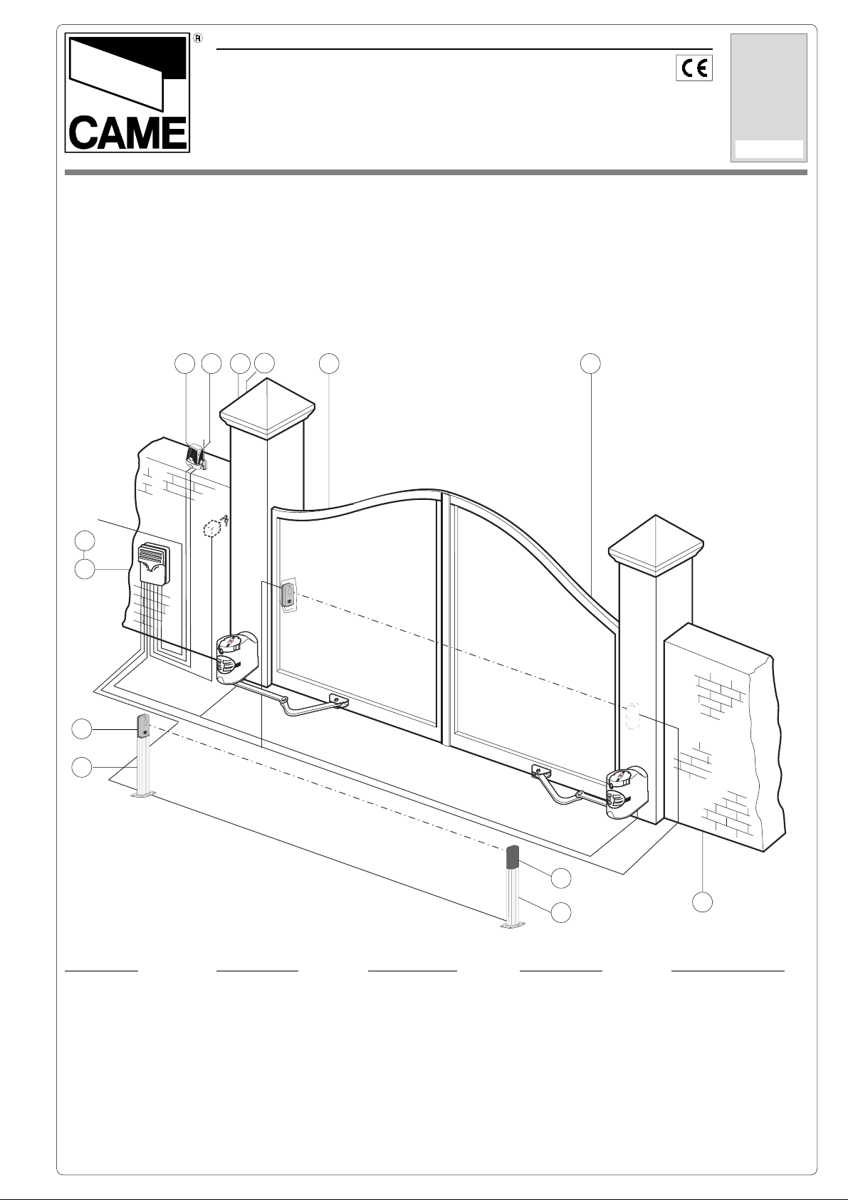
Impianto tipo
Standard installation
Installation type
Standard Montage
Instalación tipo
C
A
M
E
3 x 1,5
230 V
RG58
2 x 1,5
3
2
2 x 1
E
M
A
C
K
C
O
K
C
O
L
TX
2 x 1
L
N
U
X
R
7
4 x 1
8
*
RX
E
M
A
C
K
C
O
L
N
U
K
C
O
L
* 6 x 1,5 mm2 (20m)
6 x 2,5 mm2 (30m)
Impianto tipo
1 - Motoriduttore
Accessori:
2 - Quadro comando
3 - Ricevitore radio
4 - Antenna
5 - Lampeggiatore di
movimento
6 - Selettore a chiave
7 - Fotocellule di
sicurezza
8 - Colonnine per
fotocellule
2 x 1
Installation type
1 - Gear motor
Accessories:
2 - Control panel
3 - Radio receiver
4 - Antenna
5 - Flashing light
indicating door
movement
6 - Key-operated selector
switch
7 - Safety photocells
8 - Column for photocells
Installation type
1 - Motorédecteur
Accessoires:
2 - Armoire de
commande
3 - Récepteur radio
4 - Antenne
5 - Clignotant de
mouvement
6 - Selectueur à clé
7 - Photocellules de
sécurité
8 - Colonnes pour
photocellules
7
8
TX
Standardanlage
1 - Getriebemotor
Zubehör:
2 - Schalttafel
3 - Funkempfänger
4 - Antenne
5 - Blinkleuchte “Tor in
Bewegung”
6 - Schlüsselschalter
7 - Lichtschranken
8 - Säule für
Lichtschranken
4 x 1
1
Instalación estándar
1 - Motorreductor
Accesorios:
2 - Cuadro de mando
3 - Radiorreceptor
4 - Antena
5 - Lámpara
intermitente
de movimiento
6 - Selector con llave
7 - Fotocélulas de
seguridad
8 - Columnas para
fotocélulas
Page 2
ITALIANO
CARATTERISTICHE GENERALI
Descrizione:
- Automazione esterna a braccio snodato per cancelli a battente.
- Progettato e costruito interamente dalla CAME CANCELLI AUTOMATICI
S.p.A., risponde alle vigenti norme di sicurezza, con grado di protezione IP 54.
- Garantito 24 mesi salvo manomissioni.
Attenzione! Controllate che le apparecchiature di comando, di sicurezza e gli accessori siano originali CAME; ciò garantisce e rende
l'impianto di facile esecuzione e manutenzione.
F 7024
Motoriduttore irreversibile 24V d.c. 140W.
- Dimensione ante fino a max. 2,3 metri
(vedi tabella a pag. 4).
- Apertura dell’anta: max. 110°.
GENERAL SPECIFICATIONS
Versioni:
Limiti d'impiego:
F 7002
Braccio dritto di trasmissione con guida
di scorrimento.
H 3000
Dispositivo di sblocco a cordino (L= 5
m.) completo di contenitore di sicurezza, manopola di sblocco e pulsante.
LOCK 81
Elettroserratura di blocco a cilindro singolo.
LOCK 82
Elettroserratura di blocco a cilindro doppio.
Accessori opzionali:
ENGLISH
Description:
- External automation system with
articulated arm for hinged gates.
- Designed and constructed entirely by
CAME CANCELLI AUTOMATICI S.p.A.
in compliance with current safety
standards, and with an IP54 protecting
rating.
- Guaranteed for 24 months, unless
tampered with by unauthorized
personnel.
Versions:
F 7024
24V d.c. - 140W irreversible gearmotor.
Limits of use:
- Lenght of gate wings: up to max. 2,3
metres (see table on page 4).
- Max. angle of gate wing when open:
110°.
F 7002
Straight transmission arm with runner.
H 3000
Cable-operated (lenght 5 m.) manual
release system, complete with safety
housing, release knob and pushbutton.
LOCK 81
Single-cylinder electric lock.
LOCK 82
Double-cylinder electric lock.
Optional accessories:
Attention! to insure easy installation and conformance with current safety norms, we raccomend installation of CAME safety and
control accessories.
CARACTERISTIQUES GENERALES
FRANÇAIS
Description:
- Automatisme exterieur a bras articules
pour portails a battant.
- Il a été entièrement concu et construit
par la Société CAME CANCELLI AUT OMATICI S.p.A., conformément aux
normes de sécurité en vigueur avec
degré de protection IP 54.
- Il est garanti 24 mois sauf en cas
d'altérations..
Attention ! Vérifiez que l’appareillage de commande, de sécurité et les accessoires sont des produits originaux CAME afin de garantir
l’installation et d’en faciliter le montage et l’entretien.
F 7024
Motoréducteur irréversible 24V d.c. 140W.
- Dimension des vantaux jusqu'à max.
2,3 mètres (voir tableau en page 4).
- Ouverture du vantail: max. 110°.
Versions:
Limites d'utilisation:
Accessoires en optionopzionali:
F 7002
Bras droit de transmission avec rail.
H 3000
Dispositif de déblocage par cordelette
(L= 5 m.) comprenant le coffret de
sécur ité, bouton de déblocage et le
bouton-poussoir.
LOCK 81
Serrure électrique de blocage à barillet
unique.
LOCK 82
Serrure électrique de blocage à double
barillet.
2
Page 3
DEUTSCH
ALLGEMEINE MERKMALE
Baschreibung:
- Äussere Automatismus mit gelenkigen
Armen für Flügeltoren.
- Vollkommen von der CAME CANCELLI AUTOMATICI S.p.A. den geltenden
Sicherheitsnormen entsprechend
entwickelt und hergestellt. Schutzklasse
IP54.
- Garantie: 24 Monate, vorbehaltlich
unsachgemäßer Handhabung und
Montage.
Ausführungen:
F 7024
Nicht reversibler Getriebemotor 24V
Gleichstrom - 140W .
Einsatzgrenze:
- Torflügelabmessungen bis zu max.
2,3m. (siehe tabelle auf seite 4).
- T orflügel-Öffn ungswinkel: max. 110°.
F 7002
Gerader Antriebsarm mit Laufschiene.
H 3000
Seilentriegelungsvorrichtung (L = 5 m.)
mit Schutzgehäuse, Entriegelungs
Rebel und Drucktaster.
LOCK 81
Elektroscloß mit Einfachzylinder.
Extrazubehör:
LOCK 82
Elektroscloß mit Doppelzylinder.
Achtung! Wir empfehlen original CAME-Schalt- und -Sicherheitsvorrichtungen mit entsprechendem Zubehör zu montieren, um die
einwandfreie Montage und die problemlose Wartung der Anlage zu gewährleisten.
CARACTERISTICAS GENERALES
ESPAÑOL
Descripción:
- Automatización externa con brazo
articulado para puertas con bisagras.
- Diseñado y fabricado enteramente por
CAME CANCELLI AUT OMATICI S.p.A.,
cumple con las normas de seguridad
vigentes, con grado de protección IP54.
- Garantizado 24 meses, salvo
manipulaciones.
Modelos:
F 7024
Motorreductor irreversible 24V c.c. 140W.
Limites de empleo:
- Dimensión puertas fino a max. 2,3 metri (vedi tabella a pag. 4).
- Apertura de la puerta: max. 110°.
Accesorios complementarios:
F 7002
Brazo recto de transmisión con guía de
deslizamiento.
H 3000
Dispositivo de desbloqueo mediante
cuerda (L= 5 m.) dotato de contenedor
de seguridad, pomo de desbloqueo y
pulsador.
LOCK 81
Cerradura eléctrica de bloqueo a cilindro individual.
LOCK 82
Cerradura eléctrica de bloqueo a cilindro doble.
Atención! Comprobar que los equipos de mando, de seguridad y los acesorios sean originales CAME; lo cual garantiza y facilita el
uso y el mantenimiento del aparato.
Caratteristiche tecniche // Technical features // Caractéristiques technique // Technische Daten // Descripción técnica
TIPO
TYPE
TYPE
TYP
TIPO
F 7024
PESO
WEIGHT
POIDS
GEWICHT
PESO
9,8 Kg. 24V d.c. 11A 140W * ** 180 Nm
- Dati relativi ai valori
di alimentazione
nominale.
* Servizio intensivo.
** Regolabile mediante quadri comando
CAME.
ALIMENT AZIONE
POWER SUPPLY
ALIMENT ATION
STROMVERSORG UN -
G
ALIMENTACIÓN
- Data refers to nominal
power supply.
* Heavy-duty service.
** Can be adjusted
using CAME control
panels.
CORRENTE NOMINALE
NOMINAL CURRENT
COURANT NOMINAL
NENNSTROM
CORRIENTE NOMINAL
- Données relatives
aux valeurs
d’alimentation
nominale.
* Service intensif.
** Réglable au moyen
des armoires de
POTENZA MOTORE
MOTOR POWER
PUISSANCE MOTEUR
WIRKLEISTUNG
MOTOR
POTENCIA MOTOR
- Daten der
Stromversorgungsnennwerte.
* Intensivbetrieb.
** Über CAMESreuergeräte regelbar.
INTERMIT. LAVORO
DUTY CYCL E
INTERM. TRAVAIL
EINSCHALTDAUER
INTERM. TRABAJO
COPPIA
TORQUE
COUPLE
DREHMOMENT
PAREJA MOTOR
- Datos relativos a los
valores de la tensión
nominal.
* Service intensif,
** Ajustable mediante
los cuadros de
mando CAME.
commande CAME.
3
Page 4
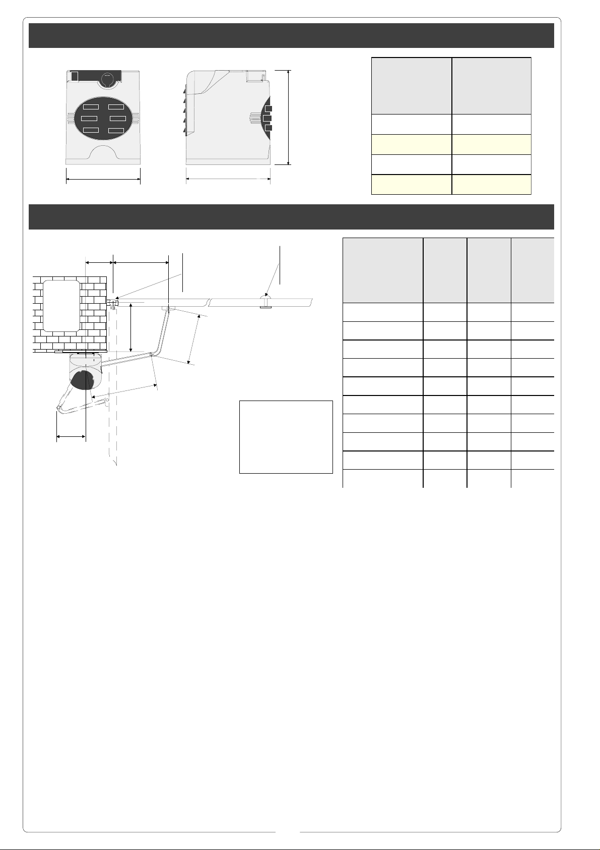
Misure di ingombro e limiti d'impiego // External dimensions and operating limits // Mesures d'encombrement limites
d'utilisation // Außenabmessungen und Einsatzbeschränkungen // Dimensiones máximas y limites de empleo
245 mm
Larghezza a n ta
Width of gate wing
Largeur du vant ai l
Torbreite
Ancho hoja
1 m 300 Kg
Peso ant a
Weight of gate wing
Poids du vantail
Torgewicht
Peso hoj a
1,5 m 250 Kg
2 m 215 Kg
194 mm
218 mm
2,3 m 200 Kg
Prima dell'installazione ... // Before installing ... // Avant d'installer l'automatisme ... // Vor den installation überprüfen ... //
Antes de instalar el automatismo ...
Angolo di apertura
Opening angle
Angle d'ouverture
Öffnungs w inkel
Ángulo de ape r t ur a
A B C
90° 137÷210 0 430
90° 137÷205 50 430
Pilastro
Pillar
Piller
Pleifer
Pilar
A
C
B
Cerniera
Hinge
Charnière
Scharnier
Bisagra
330
Battuta d'arresto
Mechanical stop
Butée d'arrêt
Anschlag
Tope de parada
90° 137÷200 75 430
i
Prima di procedere
all’installazione
dell’automatismo,
controllare che:
- la struttura del
cancello sia adeguatamente robusta, le
cerniere siano
efficienti e che non
vi sia attrito tra parti
fisse e mobili;
- il percorso dei cavi
elettrici sia eseguito
secondo le disposizioni di comando e
sicurezza (vedi
impianto tipo).
- ci sia una battuta
d’arresto meccanico
in chiusura (ben
fissata al suolo) per
evitare l’oltrecorsa
anta/motoriduttore.
330
Before proceeding
with the installation of
the automatism,
check the following:
- the structure of the
door must be sufficiently sturdy, the
hinges must be efficient and there must
be no friction between
fixed or mobile parts;
- the path of the electrical cables must be
made according to the
control and safety requirements (see the
system type);
- there must be a mechanical stop ledge
for door closing (fixed
firmly to the ground)
to prevent the door/
gearmotor from
overextending.
i = 240 mm. max
con apertura a 90°
with 90° opening angle
avec ouverture à 90°
mit 90°-Öffnungwinkel
con apertura a 90°
Avant d’installer
l’automatisme,
contrôler:
- si la structure de la
grille est
suffisamment robuste, si les charnières
sont efficaces et s’il
n’y a pas de
frottement entre les
parties fixes et
mobiles;
- si le parcours des
câbles électriques
respecte les
dispositions de
commande et de
sécurité (voir
installation type);
- s’il y a une butée
mécanique d’arrêt
en fermeture (bien
fixée au sol) pour
éviter l’extra-course
vantail/
motoréducteur.
90° 137÷195 100 430
90° 137÷190 125 430
90° 137÷185 150 400
90° 137÷180 175 400
90° 137÷175 200 400
110° 180÷210 0 430
110° 200÷205 50 430
Vor der Installation
vom Automatikantrieb
kontrollieren, ob:
- die Struktur vom Tor
auch ausreichend
stabil ist, die
Scharniere gut
funktionieren und es
keine Reibung
zwischen fest
montierten und
mobilen Teilen gibt;
- die Stromkabel auch
wirklich so verlegt
worden sind, wie für
Steuerung und
Sicherheit
vorgeschrieben ist
(siehe Anlagentyp);
- es einen
mechanischen, gut
am Boden befestigten
Torstopper in der
Offenstellung vom Tor
gibt, der verhindert,
daß der Torflügel/
Antes de comenzar
con la instalación
del automatismo,
controle que:
- la estructura de la
cancela sea robusta,
las bisagras
funcionen bien y
que no haya roces
entre las partes fijas
y móviles;
- la colocación de
los cables eléctricos
sea ejecutado según
las disposiciones de
mando y seguridad
(véase instalación
tipo).
- haya un tope de
parada mecánico en
el cierre (fijado
firmemente al piso)
para evitar el
sobrerrecorrido de
la hoja/
motorreductor.
Getriebemotor über
den Anschlag
hinauslaufen.
4
Page 5

Applicazione della piastra-base e della staffa “A” // Application of the basis-plate and of the stirrup // Application de la
piastre-guide et de l’étrier // Montage der Führungsschienen-Basis und des Steigbügels // Applicacion placa base y estribo “A”
Staffa “A”
Bracket “A”
Etrier “A”
Bügel “A”
Estribo “A”
Piastra base
Base plate
Plaque de base
Grundplatte
Placa base
ø 14ø 14
ø 14
ø 14ø 14
M8M8
M8
M8M8
M6M6
M6
M6M6
Vista frontale
Front view
Vue de face
Vorderanssicht
Vista frontal
100 mm min.
- Fissare la piastrabase al pilastro con
viti M8 e tasselli ø14
rispettando la quota
minima di 100 mm.
dalla
pavimentazione.
- Fissare la staffa
“A” (con viti M6 o
saldatura) all’anta
del cancello rispettando le quote "C"
(vedi tabella a
pagina 4) e 68 mm.
- Use M8 screws and
ø14 screw anchors to
mount the base plate
on the pillar. Be sure
to respect the 100
mm. minimum
distance from the
pavement.
- Attach bracket “A” to
the gate wing (use M6
screws or wlds). Be
sure to respect the
offsets "C" (see table
page 4) and 68 mm.
- Fixer la plaque de
base au pilier à
l’aide de vis M8 et
tampons ø14 en
respectant la cote
minimum de 100
mm. du sol.
- Fixer l’étrier “A”
(avec des vis M6 ou
par soudure) sur le
vantail du portail en
respectant les cotes
"C" (voir tableau
page 4) et 68 mm.
C
- Die Grundplatte mit
Schrauben M8 und
Dübeln ø14 auf einer
Mindesthöhe von 100
mm. über dem Boden
am Pfeiler befestigen.
- Bügel “A” (mit
Schrauben M6 oder
Schweißung) unter
Einhaltung der Maße
C (sehen Tabelle
Seite 4) und 68 mm.
68 mm
- Fijar la placa base
al pilar con tornillos
M8 y tacos ø14
respetando la cota
mínima de 100 mm.
del suelo.
- Fijar el estribo “A”
(con tornillos M6 o
saldadura) en la
puerta respetando
las cotas "C"
(vedas tabla pag. 4)
y 68 mm.
5
Page 6

Installazione // Installation // Installation // Installation // Instalación
(1) (2) (3)
(1)
Ø3,9x13Ø3,9x13
Ø3,9x13
Ø3,9x13Ø3,9x13
Aprire il tappo
copriserratura (1).
Inserire la chiave
spingerla e ruotarla
in senso orario (2).
Sollevare il coperchio, allentare la vite
Ø 3,9x13 e togliere il
coperchio dal
gruppo
motoriduttore (3).
(4)
Open the lock cover
cap (1).
Push the key in and
turn clockwise (2).
Raise the cover,
loosen the Ø 3.9x13
screw and remov e the
cover from the
gearmotor unit (3).
M8x90M8x90
M8x90
M8x90M8x90
Enlever le bouchon
qui recouvre la
serrure (1).
Introduire la clé, la
pousser et la
tourner dans le sens
des aiguilles d’une
montre (2).
Soulever le petit
couvercle, desserrer
la vis Ø 3,9x13 et
enlever le couvercle
du groupe
motoréducteur (3).
Die Schloßabdeckung
(1) aufmachen.
Den Schlüssel ins
Schloß stecken und
im Uhrzeigersinn (2)
drehen.
Die kleine Abdeckung
anheben, die
Schraube Ø 3,9x13
lösen und die
Abdeckung von der
Einheit mit
Getriebemotor (3)
abnehmen.
Abra el tapón que
cubre la cerradura
(1).
Introduzca la llave,
empújela y gírela hacia la derecha (2).
Levante la tapa, afloje el tornillo Ø 3,9x13
y quite la tapa del
grupo motorreductor
(3).
Inserire il
motoriduttore nella
piastra-base in
corrispondenza dei 4
fori e fissarlo con le
due viti M8x90 e
relativi dadi M8 in
dotazione (4).
M8M8
M8
M8M8
Insert the gearmotor
in the base-plate in
correspondence with
the 4 holes and secure it with the two
M8x90 screws and related M8 nuts provided (4).
Placer le
motoréducteur dans
la plaque de base en
correspondance des
4 trous et le fixer à
l’aide des deux vis
M8x90 et des écrous
M8 correspondants
fournis de série (4).
6
Den Getriebemotor so
auf die Grundplatte
setzen, daß die vier
Löcher übereinstimmen, und mit den
beiden mitgelieferten
Schrauben M8x90
und den dazugehörig-
en Muttern M8 (4)
befestigen.
Coloque el
motorreductor en la
placa de base, haciendo coincidir los
4 orificios y fíjelo
con los dos tornillos
M8x90 y las tuercas
M8 (4) respectivas
suministradas.
Page 7

Applicazione del braccio snodato // Application of the articulated arm // Application du bras articulé // Anbringung vom
Gelenkarm // Aplicación del brazo articulado
M12x40M12x40
M12x40
M12x40M12x40
"Staffa A""Staffa A"
"Staffa A"
"Staffa A""Staffa A"
M12M12
M12
M12M12
SpinaSpina
Spina
SpinaSpina
ø 10x40ø 10x40
ø 10x40
ø 10x40ø 10x40
ø 10x35ø 10x35
ø 10x35
ø 10x35ø 10x35
M10x14M10x14
M10x14
M10x14M10x14
- Inserire la spina
Ø10x40 e il braccio
diritto nell’albero del
motoriduttore e fissarlo con la vite
M10x14 e relativa rosetta Ø10x35. Lubrificare il perno del
braccio diritto. Unire
e fissare i due bracci
con la vite M6x10 e
relativa rosetta
Ø6x24. Sbloccare il
motoriduttore e fissare il braccio curvo
alla staffa “A” con la
vite M12x40 ed il relativo dado M12 verificandone il libero
scorrimento. Per applicazione a destra vedere fig. 2.
- Insert the Ø10x40
pin and the straight
arm into the shaft of
the gearmotor and secure it with the
M10x14 screw and related Ø10x35 washer .
Lubricate the pin of
the straight arm. Join
and secure the two
arms with the M6x10
screw and related
Ø6x24 washer. Release the ratiomotor
and fix the curved arm
to the bracket “A” with
the M12x40 screw
and the related M12
nut, checking its free
sliding. For application
on the right-hand side
see fig. 2.
M6x10M6x10
M6x10
M6x10M6x10
- Introduire la
cheville Ø10x40
ainsi que le bras
droit dans l’arbre du
motoréducteur et le
fixer à l’aide de la
vis M10x14 et de la
rondelle Ø10x35
correspondante.
Lubrifier le pivot du
bras droit. Unir et
fixer les deux bras à
l’aide de la vis
M6x10 et de la rondelle Ø6x24
correspondante.
Débloquer le
motoréducteur et
fixer le bras
recourbé à la bride
“A” à l’aide de la vis
M12x40 et de l’écrou
M12 correspondant
en contrôlant s’il
coulisse correctement. Voir la fig. 2
pour l’application à
droite.
7
ø 6x24ø 6x24
ø 6x24
ø 6x24ø 6x24
Den Stecker Ø 10x40
und den geraden Arm
in die Welle vom
Getriebemotor
stecken und mit der
Schraube M10x14
und der dazugehörig-
en Unterlegscheibe Ø
10x35 befestigen. Den
Zapfen vom ger aden
Arm abschmieren. Die
beiden Arme mit der
Schraube M6x10 und
der dazugehörigen
Unterlegscheibe Ø
6x24 verbinden und
befestigen. Den
Getriebemotor
entriegeln und den
gebogenen Arm mit
der Schraube M12x40
und der dazugehörig-
en Mutter M12 am
Bügel A befestigen.
Dabei darauf achten,
daß der Arm frei
laufen kann. Für die
Anbringung auf der
rechten Seite siehe
Abb. 2.
Fig. 2
- Introduzca el perno
Ø10x40 y el brazo
recto en el árbol del
motorreductor y fíjelo con los tornillos
M10x14 y la arandela respectiva
Ø10x35. Lubrique el
perno del brazo recto. Una y fije los dos
brazos con el tornillo M6x10 y la arandela respectiva
Ø6x24. Desbloquee
el motorreductor y
fije el brazo curvo al
estribo “A” con el
tornillo M12x40 y la
tuerca M12 respectiva, compr obando
que se deslice libremente. Para aplicación a la derecha,
véase fig. 2.
Page 8

Collegamenti elettrici al quadro elettrico ZL19 - ZL170 // Electrical connections to the ZL19 - ZL170 board // Branchements électriques
au tableau ZL19 - ZL170 // Stromanschlüsse an die Schalttafel ZL19 - ZL170 // Conexiones eléctricas al cuadro ZL19 - ZL170
Installare il quadro
comando e procedere
ai collegamenti
elettrici come indicato in figura.
RRcFa
FM
* Motoriduttore ritardato in apertura
* Motoréducteur retardé en ouverture
* Getriebemotor mit Verzögerung beim Öffnen.
* Motorreductor con apertura retardada
Install the electrical
control panel and
connect the wiring as
indicated.
Installer l’armoire de
commande et réaliser
les branchements
électriques de la
manière indiquée.
Die Schalttafel
installieren und die
elektrischen
Anschlüsse wie
angegeben ausführen.
N.B.: per installazione a destra vista interna, invertire le fasi M-N.
N.B.: for installation to the right of the internal view, invert the M-N phases.
N.B.: inverser les phases M-N pour l'installation à droite vue interne.
Bitte beachten: Für die Installation rechts, nach innen zeigend, die Phasen M
und N vertauschen.
N.B.: para instalación a la derecha vista interna, invierta las fases M-N.
M2**M1*
N
** Motoriduttore ritardato in chiusura
* Gearmotor delayed during opening
** Gearmotor delayed during closure
** Motoréducteur retardé en fermeture
** Getriebemotor mit Verzögerung beim Schließen
** Motorreductor con cierre retardado
Installar el cuadro de
mando y proceder a
las conexiones
eléctricos según lo
indicado.
RRcFa
FM
N
RRcFaF
M1*
MN
M1 N1 M2 N2
ZL19
FUSIBILE
CENTRALINA
2A
FUS.IBILE
LINEA 5A
FUS.IBILE
LINEA 5A
T.L. T.C.A.
21 3 45678910
QUADRO COMANDO
ZE4
RA1 RC1 RA2 RC2CFA1 FC1CFA2 FC2
ON
C
M2**
C
N
RRcFa
FM
ZL170
FUSIBILE
CENTRALINA
2A
FUS.IBILE
LINEA 5A
FUS.IBILE
LINEA 5A
T.L. T.C.A .
21 3 45678910
QUADRO COMANDO
ZE4
ON
RRcFaF
RA R RC FA F M N
1
2
MN
ADT x ZL170
MN R
MNR
8
Page 9

Regolazione microinterruttore di stop in apertura e di rallentamento in chiusura // Adjustment of stop microswitch during opening
and slowing while closing // Réglage du microinterrupteur d'arrêt en ouverture et de ralentissement en fermeture // Einstellung
Mikroschalter für Stop beim Öffnen und Soft-Stop beim Schließen // Regulación del microinterruptor de parada durante la
apertura y de deceleracón durante el cierre
Camma superiore
Upper cam
Came supérieure
oberer Nocken
Leva superior
Camma inferiore
Lower cam
Came inférieure
unter Nocken
Leva inferior
Regolazione
microinterruttore di
stop in apertura:
sbloccare il
motoriduttore (1) e
portare l’anta nella
posizione di apertura
desiderata (2).
Ruotare la camma
inferiore fino a far
inserire il
Adjustment of stop
microswitch during
opening: release the
gearmotor (1) and
allow the door to reach
the opening position
desired (2). Turn the
lower cam clockwise
until the microswitch is
inserted and lock it with
the central screw (3).
microinterruttore e
bloccarla con la vite
centrale (3).
(1) (2)
Manopola
Knob
Poignée
Vierkantwelle
Manilla
Réglage du
microinterrupteur
d'arrêt en ouverture:
débloquer le
motoréducteur (1) et
mettre le portail dans
la position d’ouvertu-
re voulue (2). Tourner
la came inférieure
dans le sens des
aiguilles d’une
montre jusqu’à ce
que le microcontact
s’enclenche et la
bloquer avec la vis
qui se trouve au
centre (3).
Microinterrutore
Microswitches
Microcontacts
Mikroschalter
Microinterruptores
Einstellung
Mikroschalter für Stop
beim Öffnen: Den
Getriebemotor (1)
entriegeln und den
Torflügel in die
gewünschte
Öffnungsstellung (2)
bringen. Die untere
Nocke im
Uhrzeigersinn drehen,
bis sich der
Mikroschalter einfügt,
und dann mit der
mittleren Schraube (3)
blockieren.
Camma inferiore
(3)
Lower cam
Came inférieure
unter Nocken
Leva inferior
Regulación del
microinterruptor de
parada durante la
apertura: desbloquee
el motorreductor (1) y
coloque la hoja en la
posición de apertura
deseada (2). Gire la
leva inferior hacia la
derecha hasta hacer
enganchar el
microinterruptor, y
bloquéela con el tornillo central (3).
Regolazione
microinterruttore di
rallentamento in
chiusura: portare
l’anta a circa 10 cm
dalla battuta d'arresto
in chiusura (4).
Ruotare la camma
superiore fino a far
inserire il
microinterruttore e
bloccarla con le due
viti superiori (5).
Adjustment of slowingdown micro-switch during closing: place the
door at approximately
10 cm from the endstop during closure (4).
Tur n the upper cam anticlockwise until the
microswitch is inserted
and lock it with the two
upper screws (5).
Réglage du
microinterrupteur de
ralentissement en
fermeture: mettre le
vantail à environ 10
cm de la butée d'arrêt
en fermeture (4).
Tourner la came
supérieure dans le
sens contraire aux
aiguilles d’une
montre jusqu’à ce
que le microcontact
s’enclenche et la
bloquer avec les deux
vis qui se trouvent en
haut (5).
(4) (5)
Battuta d'arresto
Mechanical stop
Butée d'arrêt
Anschlag
Tope de parada
Camma superiore
10 cm
9
Einstellung
Mikroschalter für SoftStop beim Schließen:
den Flügel auf ca. 10
cm von Anschlag für
den Torstop während
des Schließens bringen
(4). Die obere Nocke
gegen den
Uhrzeigersinn drehen,
bis sich der
Mikroschalter einfügt,
und dann mit den
beiden oberen
Schrauben (5)
blockieren.
Upper cam
Came supérieure
oberer Nocken
Leva superior
Microinterrutore
Microswitches
Microcontacts
Mikroschalter
Microinterruptores
Vite centrale
Central screw
Vis centre
Mittleren Schraube
Tornillo central
Regulación del
microinterruptor de
deceleración durante
el cierre: coloque la
hoja a alrededor de
10 cm del tope de parada durante el cierre
(4). Gire la leva superior hacia la izquierda
hasta hacer enganchar el
microinterruptor, y
bloquéela con los dos
tornillos superiores
(5).
VV
Viti superiori
VV
Upper screws
Vis haut
Oberen Schrauben
Tornillos superiores
Microinterrutore
Microswitches
Microcontacts
Mikroschalter
Microinterruptores
Page 10

Montaggio coperchio // Cover Assembly // Montage du couvercle // Montage der Abdeckung // Montaje de la tapa
Dopo aver ultimato
le operazioni di montaggio, collegamenti
elettrici e regolazioni, inserire il coperchio fissandolo
con la vite Ø3,9x13.
Inserire la manopola
di sblocco in posizione "LOCK" e fissarla.
After completing the
assembly operations,
electrical connections
and adjustments, insert the lid and secure
it with the Ø3.9x13
screw. Insert the release knob in “LOCK”
position and secure it.
ø 3,9x13ø 3,9x13
ø 3,9x13
ø 3,9x13ø 3,9x13
Placer le couvercle
en le fixant avec la
vis Ø3,9x13 après
avoir terminé les
opérations de
montage, les
branchements
électriques et le
réglage. Mettre le
bouton de déblocage
sur “LOCK” et le fixer.
Nach Beendigung
der Montage und
Durchführung der
Stromanschlüsse
und Einstellungen
die Abdeckung
einsetzen und mit
der Schraube
Ø3,9x13 befestigen.
Den
Entriegelungsgriff auf
“LOCK” stellen und
blockieren.
T ras haber conc luido los trabajos de
montaje, conexiones
eléctricas y regulaciones, introduzca la
tapa fijándola con el
tornillo Ø3,9x13. Coloque la manecilla
de desbloqueo en
poción “LOCK” y fí-
jela.
10
Page 11

Accessori opzionali // Optional accessories // Accessoires sur demande // Zubehör auf Anfrage // Accesorios opcionales
H3000 - Dispositivo
di sblocco a cordino
(L = 5 m.) completo
di contenitore di sicurezza, manopola
di sblocco e pulsante.
NOTA: evitare di formare con il cordino
di sblocco angoli
acuti (1) o retti (2).
H3000 - Disposal of
connecting-release (L
= 5 m.) complete of
surety-container,
release hand grip and
push-button.
NOTE: avoid to create
any acute or right
angle with the
release-connector.
H3000 - Mechanism
de débloquage
coordonné (L = 5 m.)
complet de récipient
de sureté, poignée
de débloquage et
bouton.
NOTE: on ne doit
pas créer d’ngles
droits ou aigus avec
le débloquage.
Contenitore di sicurezza
Protective casing
Boítier de sécurité
Schutzkasten
Contenidor de seguridad
H3000- Aufhebungsvorrichtung (L = 5 m.)
mit Sicherheitsbehälter, Griff und
Knöpfchen.
ACHTUNG: man
muss keinen rechten
oder spitzen Winkel
bilden.
H3000 - Dispositivo
de desbloqueo a
cuerda (L= 5 m.), con
caja de seguridad,
manilla de
desbloqueo y botón.
NOTA: evitar formar
angulos rectos o
agudos con la
cuerda.
H 3000
Molla
Spring
Ressort
Feder
Muelle
Astina
Small bar
Tige
Stange
Varilla
Cordino
Cord
Cordelette
Bowdenzug
Cuerda
11
Page 12

Manutenzioni periodiche // Periodic maintenance // Entretiens périodiques // Regelmäßige Wartung // Mantenimiento periódico
Il gruppo non necessita di alcuna manutenzione specifica.
Solo come misura
cautelativa e in caso
di servizio intensivo
è opportuno controllare l'integrità del
cavo elettrico collegato al motore e
ingrassare i punti di
scorrimento tra parti
fisse e mobili.
The unit does not
need any specific
maintenance. It is just
recommended to
check that the electric
cable connected to
the motor is in good
condition and to lubricate the points of sliding between fixed and
mobile parts as a preventive measure and
in the event of intense
use.
Le groupe ne
nécessite d’aucun
entretien spécifique.
Il est juste conseillé
de contrôler si le
câble électrique
branché au moteur
est en bon état et de
graisser les points
de glissement entre
les parties fixes et
mobiles pour plus de
sûreté et en cas
d’usage intensif.
Die Einheit macht
keine besondere
Wartung nötig. Als
Vorsichtsmaßnahme
und bei intensiver
Torbeanspruchung
sollten das
Stromkabel am Motor
auf seine
Unversehrtheit
überprüft und die
Laufstellen zwischen
fest montierten und
beweglichen Teilen
abgeschmiert werden.
El grupo no requiere
ningún mantenimiento específico.
Sólo como medida
preventiva, es opor tuno controlar la integridad del cable
eléctrico conectado
al motor e engrasar
los puntos de deslizamiento entre las
piezas fijas y móvi-
les.
Tutti i dati sono stati controllati con la
massima cura. Non ci assumiamo comunque alcuna responsabilità per
eventuali errori od omissioni.
ASSISTENZA TECNICA
NUMERO VERDE
800 295830
EB
W
www.came.it
E-MAIL
CANCELLI AUTOMATICI
CAME CANCELLI AUTOMATICI S.P.A.
DOSSON DI CASIER (TREVISO)
(+39) 0422 4940 (+39) 0422 4941
info@came.it
All data checked with the maximum care.
However, no liability is accepted for any error
or omission.
SISTEMA QUALITÀ
CERTIFICATO
CAME LOMBARDIA S.R.L.______COLOGNO M. (MI)
(+39) 02 26708293 (+39) 02 25490288
CAME SUD S.R.L. ___________________NAPOLI
(+39) 081 7524455 (+39) 081 7529109
CAME (AMERICA) L.L.C.____________MIAMI ( FL)
(+1) 305 5930227 (+1) 305 5939823
CAME AUTOMATISMOS S.A__________MADRID
(+34) 091 5285009 (+34) 091 4685442
CAME BELGIUM__________________LESSINES
(+32) 068 333014 (+32) 068 338019
Toutes les données ont été contrôlées
très soigneusement. Nous n’assumons
de toute façon aucune responsabilité pour
les erreurs ou omissions éventuelles.
Die Daten wurden mit höchster Sorgfalt
geprüft. Für eventuelle Fehler oder
Auslassungen übernehmen wir keine
Haftung.
CAME FRANCE S.A.____NANTERRE CEDEX (PARIS)
(+33) 01 46130505 (+33) 01 46130500
CAME GMBH________KORNTAL BEI (STUTTGART)
(+49) 07 11839590 (+49) 07 118395925
CAME GMBH____________SEEFELD BEI (BERLIN)
(+49) 03 33988390 (+49) 03 339885508
CAME PL SP.ZO.O______________WARSZAWA
(+48) 022 8365076 (+48) 022 8369920
CAME UNITED KINGDOM LTD___NOTTINGHAM
(+44) 0115 9210430 (+44) 0115 9210431
Todos los datos se han controlado con
la máxima atención. No obstante no nos
responsabilizamos de los posibles
errores u omisiones.
 Loading...