

Page 1
CANCELLI AUTOMATICI
AUTOMAZIONE ESTERNA A BRACCI SNODATI PER CANCELLI A BATTENTE
EXTERNAL AUTOMATION SYSTEM WITH ARTICULATED ARMS FOR HINGED GATES
AUTOMATISME EXTERIEUR A BRAS ARTICULES POUR PORTAILS A BATTANT
ÄUSSERE AUTOMATISMUS MIT GELENKIGEN ARMEN FÜR FLÜGELTOREN
AUTOMATIZACIÓN EXTERNA CON BRAZOS ARTICULADOS PARA PUERTAS CON BISAGRAS
C
AM
SERIE FAST |
FAST SERIES
|
SÉRIE FAST |
BAUREIHE FAST
|
F7000 - F7001
45 6 7 7
E
SERIE FAST
Documentazione
Tecnica
S55
rev. 1.1
02/2003
©
CAME
CANCELLI
AUTOMATICI
119DS55
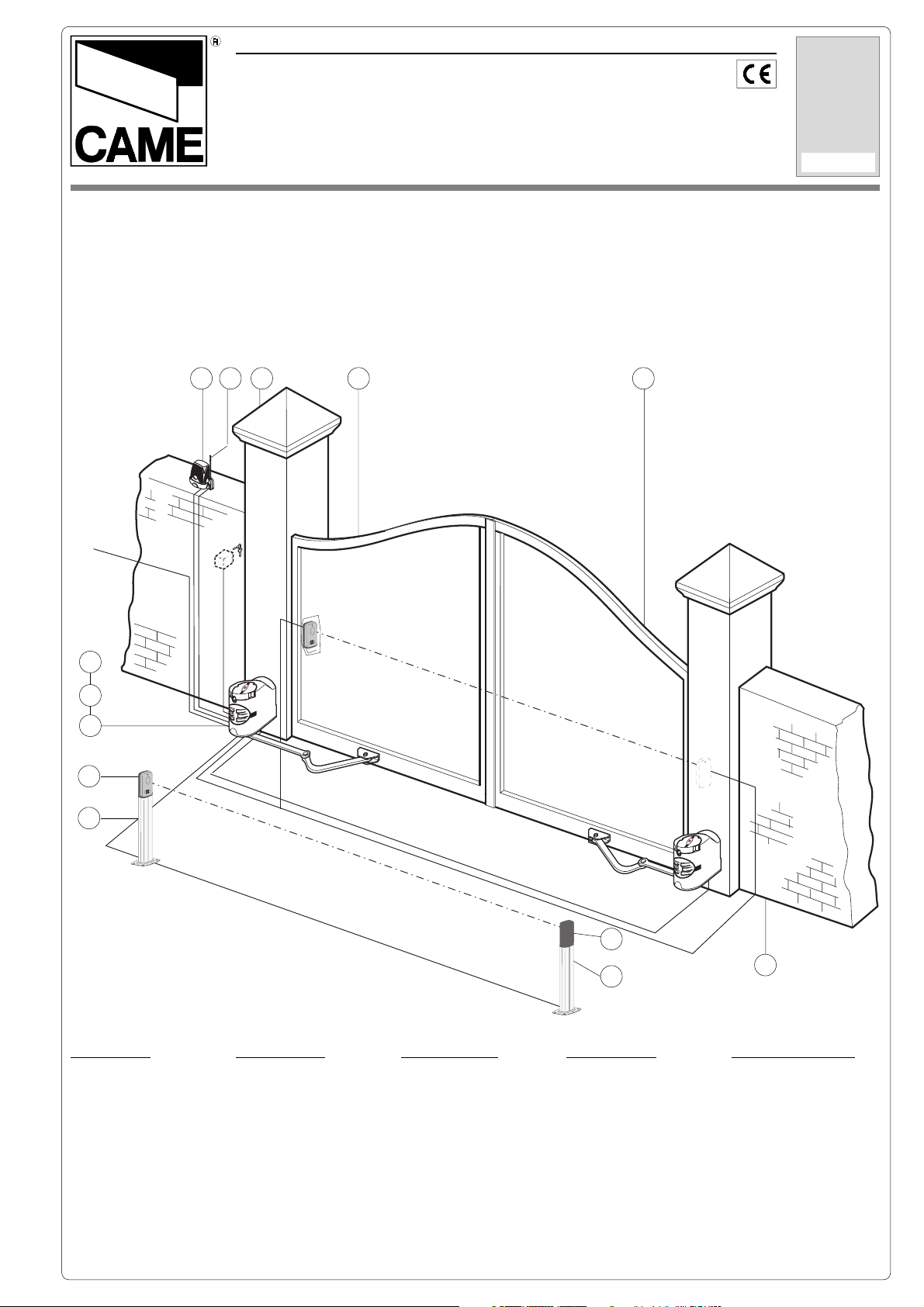
Impianto tipo
Standard installation
Installation type
Standard Montage
Instalación tipo
230 V
3
2
1
7
8
3 x 1,5
RX
2 x 1,5
4 x 1
RG58
2 x 1
TX
2 x 1
E
M
A
C
K
C
O
L
N
U
K
C
O
L
RX
E
M
A
C
K
C
O
L
N
U
K
C
O
L
2 x 1
7
8
4 x 1,5
4 x 1
1
Impianto tipo
1 - Motoriduttore
Accessori:
2 - Quadro comando
3 - Ricevitore radio
4 - Antenna
5 - Lampeggiatore di
movimento
6 - Selettore a chiave
7 - Fotocellule di
sicurezza
8 - Colonnine per
fotocellule
Installation type
1 - Gear motor
Accessories:
2 - Control panel
3 - Radio receiver
4 - Antenna
5 - Flashing light
indicating door
movement
6 - Key-operated selector
switch
7 - Safety photocells
8 - Column for photocells
Installation type
1 - Motorédecteur
Accessoires:
2 - Armoire de
commande
3 - Récepteur radio
4 - Antenne
5 - Clignotant de
mouvement
6 - Selectueur à clé
7 - Photocellules de
sécurité
8 - Colonnes pour
photocellules
TX
Standardanlage
1 - Getriebemotor
Zubehör:
2 - Schalttafel
3 - Funkempfänger
4 - Antenne
5 - Blinkleuchte “Tor in
Bewegung”
6 - Schlüsselschalter
7 - Lichtschranken
8 - Säule für
Lichtschranken
Instalación estándar
1 - Motorreductor
Accesorios:
2 - Cuadro de mando
3 - Radiorreceptor
4 - Antena
5 - Lámpara
intermitente
de movimiento
6 - Selector con llave
7 - Fotocélulas de
seguridad
8 - Columnas para
fotocélulas
Page 2
ITALIANO
CARATTERISTICHE GENERALI
Descrizione:
- Automazione esterna a braccio snodato per cancelli a battente.
- Progettato e costruito interamente dalla CAME CANCELLI AUTOMATICI
S.p.A., risponde alle vigenti norme di sicurezza, con grado di protezione IP 54.
- Garantito 24 mesi salvo manomissioni.
Attenzione! Controllate che le apparecchiature di comando, di sicurezza e gli accessori siano originali CAME; ciò garantisce e rende
l'impianto di facile esecuzione e manutenzione.
F 7000
Motoriduttore irreversibile 230V a.c. 160W con quadro elettrico incorporato.
F 7001
Motoriduttore irreversibile 230V a.c. 160W.
- Dimensione ante fino a max. 2,3 metri
(vedi tabella a pag. 4).
- Apertura dell’anta: max. 110°.
GENERAL SPECIFICATIONS
Versioni:
Limiti d'impiego:
H 3000
Dispositivo di sblocco a cordino (L= 5
m.) completo di contenitore di sicurezza, manopola di sblocco e pulsante.
LOCK 81
Elettroserratura di blocco a cilindro singolo.
LOCK 82
Elettroserratura di blocco a cilindro doppio.
Accessori opzionali:
ENGLISH
Description:
- External automation system with
articulated arm for hinged gates.
- Designed and constructed entirely by
CAME CANCELLI AUTOMATICI S.p.A.
in compliance with current safety
standards, and with an IP54 protecting
rating.
- Guaranteed for 24 months, unless
tampered with by unauthorized
personnel.
Versions:
F 7000
230V a.c. - 160W irreversible gearmotor
with integrated electric panel.
F 7001
230V a.c. - 160W irreversible gearmotor.
Limits of use:
- Lenght of gate wings: up to max. 2,3
metres (see table on page 4).
- Max. angle of gate wing when open:
110°.
H 3000
Cable-operated (lenght 5 m.) manual
release system, complete with safety
housing, release knob and pushbutton.
LOCK 81
Single-cylinder electric lock.
LOCK 82
Double-cylinder electric lock.
Optional accessories:
Attention! to insure easy installation and conformance with current safety norms, we raccomend installation of CAME safety and
control accessories.
CARACTERISTIQUES GENERALES
FRANÇAIS
Description:
- Automatisme exterieur a bras articules
pour portails a battant.
- Il a été entièrement concu et construit
par la Société CAME CANCELLI AUTOMATICI S.p.A., conformément aux
normes de sécurité en vigueur avec
degré de protection IP 54.
- Il est garanti 24 mois sauf en cas
d'altérations..
Attention ! Vérifiez que l’appareillage de commande, de sécurité et les accessoires sont des produits originaux CAME afin de garantir
l’installation et d’en faciliter le montage et l’entretien.
F 7000
Motoréducteur irréversible 230V a.c. 160W avec tableau électrique incorporé.
F 7001
Motoréducteur irréversible 230V a.c. 160W.
- Dimension des vantaux jusqu'à max.
2,3 mètres (voir tableau en page 4).
- Ouverture du vantail: max. 110°.
Versions:
Limites d'utilisation:
Accessoires en optionopzionali:
H 3000
Dispositif de déblocage par cordelette
(L= 5 m.) comprenant le coffret de
sécurité, bouton de déblocage et le
bouton-poussoir.
LOCK 81
Serrure électrique de blocage à barillet
unique.
LOCK 82
Serrure électrique de blocage à double
barillet.
2
Page 3
DEUTSCH
ALLGEMEINE MERKMALE
Baschreibung:
- Äussere Automatismus mit gelenkigen
Armen für Flügeltoren.
- Vollkommen von der CAME CANCELLI AUTOMATICI S.p.A. den geltenden
Sicherheitsnormen entsprechend
entwickelt und hergestellt. Schutzklasse
IP54.
- Garantie: 24 Monate, vorbehaltlich
unsachgemäßer Handhabung und
Montage.
Ausführungen:
F 7000
Nicht reversibler Getriebemotor 230V
Wechselstrom - 160W mit eingebauter
Schalttafel.
F 7001
Nicht reversibler Getriebemotor 230V
Wechselstrom - 160W.
Einsatzgrenze:
H 3000
Seilentriegelungsvorrichtung (L = 5 m.)
mit Schutzgehäuse, Entriegelungs
Rebel und Drucktaster.
LOCK 81
Elektroscloß mit Einfachzylinder.
LOCK 82
Elektroscloß mit Doppelzylinder.
Extrazubehör:
- Torflügelabmessungen bis zu max.
2,3m. (siehe tabelle auf seite 4).
- Torflügel-Öffnungswinkel: max. 110°.
Achtung! Wir empfehlen original CAME-Schalt- und -Sicherheitsvorrichtungen mit entsprechendem Zubehör zu montieren, um die
einwandfreie Montage und die problemlose Wartung der Anlage zu gewährleisten.
CARACTERISTICAS GENERALES
ESPAÑOL
Descripción:
- Automatización externa con brazo
articulado para puertas con bisagras.
- Diseñado y fabricado enteramente por
CAME CANCELLI AUTOMATICI S.p.A.,
cumple con las normas de seguridad
vigentes, con grado de protección IP54.
- Garantizado 24 meses, salvo
manipulaciones.
Modelos:
F 7000
Motorreductor irreversible 230V c.a. 160W con cuadro eléctrico incorporado.
F 7001
Motorreductor irreversible 230V c.a. 160W.
Limites de empleo:
- Dimensión puertas fino a max. 2,3 metri (vedi tabella a pag. 4).
- Apertura de la puerta: max. 110°.
Accesorios complementarios:
H 3000
Dispositivo de desbloqueo mediante
cuerda (L= 5 m.) dotato de contenedor
de seguridad, pomo de desbloqueo y
pulsador.
LOCK 81
Cerradura eléctrica de bloqueo a cilindro individual.
LOCK 82
Cerradura eléctrica de bloqueo a cilindro doble.
Atención! Comprobar que los equipos de mando, de seguridad y los acesorios sean originales CAME; lo cual garantiza y facilita el
uso y el mantenimiento del aparato.
Caratteristiche tecniche // Technical features // Caractéristiques technique // Technische Daten // Descripción técnica
TIPO
TYPE
TYPE
TYP
TIPO
F 7000
F 7001 9,8 Kg 230V a.c. 1,4 A 160 W 30 % *180 N.m 10 µF
PESO
WEIGHT
POIDS
GEWICHT
PESO
11,6 Kg. 230V a.c. 1,4 A 160 W 30 %
ALIMENTAZIONE
POWER SUPPLY
ALIMENTATION
STROMVERSORG-
UNG
ALIMENTACIÓN
CORRENTE
NOMINALE
NOMINAL CURRENT
COURANT NOMINAL
NENNSTROM
CORRIENTE
NOMINAL
POTENZA MOTORE
MOTOR POWER
PUISSANCE
MOTEUR
WIRKLEISTUNG
MOTOR
POTENCIA MOTOR
INTERMIT. LAVORO
DUTY CYCLE
INTERM. TRAVAIL
EINSCHALTDAUER
INTERM. TRABAJO
COPPIA
TORQUE
COUPLE
DREHMOMENT
PAR EJA MOTOR
*180 N.m
CONDENSATORE
CAPACITOR
CONDENSATEUR
KONDENSATOR
CONDENSADOR
10 µF
- Dati relativi ai valori di alimentazione nominale - * Regolabile mediante quadri comando CAME.
- Data refers to nominal power supply - * Can be adjusted using CAME control panels.
- Données relatives aux valeurs d’alimentation nominale - * Réglable au moyen des armoires de commande CAME.
- DAten der Stromversorgungsnennwerte - * Ûber CAME-Sreuergeräte regelbar.
- Datos relativos a los valores de la tensión nominal. - * Ajustable mediante los cuadros de mando CAME.
3
Page 4
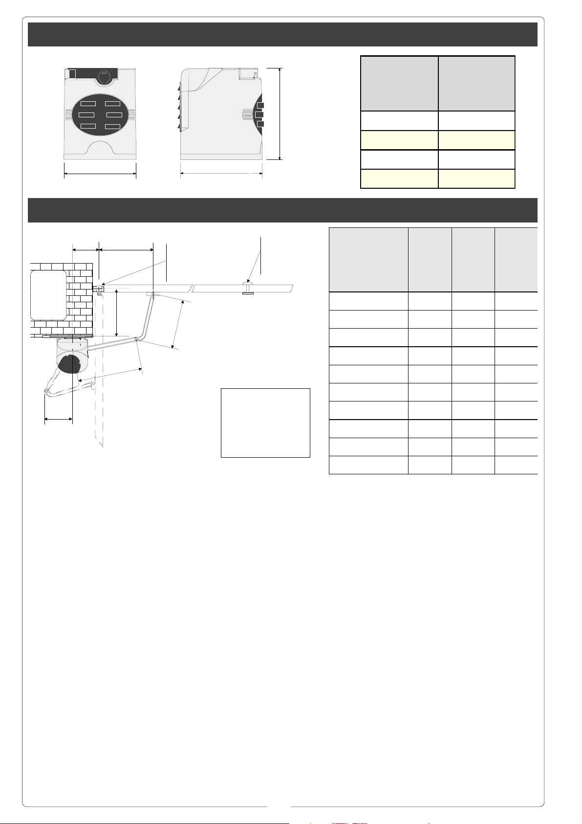
Misure di ingombro e limiti d'impiego // External dimensions and operating limits // Mesures d'encombrement limites
d'utilisation // Außenabmessungen und Einsatzbeschränkungen // Dimensiones máximas y limites de empleo
Larghezza anta
Width of gate wing
Largeur du vantail
Torbreite
Ancho hoja
245 mm
1 m 300 Kg
Peso anta
Weight of gate wing
Poids du vantail
To rg e w ic h t
Peso hoja
1,5 m 250 Kg
2 m 215 Kg
194 mm
218 mm
2,3 m 200 Kg
Prima dell'installazione ... // Before installing ... // Avant d'installer l'automatisme ... // Vor den installation überprüfen ... //
Antes de instalar el automatismo ...
Angolo di apertura
Opening angle
Angle d'ouverture
Öffnungswinkel
Ángulo de apertura
A B C
90° 137÷210 0 430
90° 137÷205 50 430
Pilastro
Pillar
Piller
Pleifer
Pilar
A
C
B
Cerniera
Hinge
Charnière
Scharnier
Bisagra
330
Battuta d'arresto
Mechanical stop
Butée d'arrêt
Anschlag
Tope de parada
90° 137÷200 75 430
330
i
Prima di procedere
all’installazione
dell’automatismo,
controllare che:
- la struttura del
cancello sia
adeguatamente
robusta, le cerniere
siano efficienti e che
non vi sia attrito tra
parti fisse e mobili;
- il percorso dei cavi
elettrici sia eseguito
secondo le
disposizioni di
comando e
sicurezza (vedi
impianto tipo).
- ci sia una battuta
d’arresto meccanico
in chiusura (ben
fissata al suolo) per
evitare l’oltrecorsa
anta/motoriduttore.
Before proceeding
with the installation of
the automatism,
check the following:
- the structure of the
door must be sufficiently sturdy, the
hinges must be efficient and there must
be no friction between
fixed or mobile parts;
- the path of the electrical cables must be
made according to the
control and safety requirements (see the
system type);
- there must be a mechanical stop ledge
for door closing (fixed
firmly to the ground)
to prevent the door/
gearmotor from
overextending.
i = 240 mm. max
con apertura a 90°
with 90° opening angle
avec ouverture à 90°
mit 90°-Öffnungwinkel
con apertura a 90°
Avant d’installer
l’automatisme,
contrôler:
- si la structure de la
grille est
suffisamment robuste, si les charnières
sont efficaces et s’il
n’y a pas de
frottement entre les
parties fixes et
mobiles;
- si le parcours des
câbles électriques
respecte les
dispositions de
commande et de
sécurité (voir
installation type);
- s’il y a une butée
mécanique d’arrêt
en fermeture (bien
fixée au sol) pour
éviter l’extra-course
vantail/
motoréducteur.
90° 137÷195 100 430
90° 137÷190 125 430
90° 137÷185 150 400
90° 137÷180 175 400
90° 137÷175 200 400
110° 180÷210 0 430
110° 200÷205 50 430
Vor der Installation
vom Automatikantrieb
kontrollieren, ob:
- die Struktur vom Tor
auch ausreichend
stabil ist, die
Scharniere gut
funktionieren und es
keine Reibung
zwischen fest
montierten und
mobilen Teilen gibt;
- die Stromkabel auch
wirklich so verlegt
worden sind, wie für
Steuerung und
Sicherheit
vorgeschrieben ist
(siehe Anlagentyp);
- es einen
mechanischen, gut am
Boden befestigten
Torstopper in der
Offenstellung vom Tor
gibt, der verhindert,
daß der Torflügel/
Antes de comenzar
con la instalación
del automatismo,
controle que:
- la estructura de la
cancela sea robusta,
las bisagras
funcionen bien y
que no haya roces
entre las partes fijas
y móviles;
- la colocación de
los cables eléctricos
sea ejecutado según
las disposiciones de
mando y seguridad
(véase instalación
tipo).
- haya un tope de
parada mecánico en
el cierre (fijado
firmemente al piso)
para evitar el
sobrerrecorrido de
la hoja/
motorreductor.
Getriebemotor über
den Anschlag
hinauslaufen.
4
Page 5
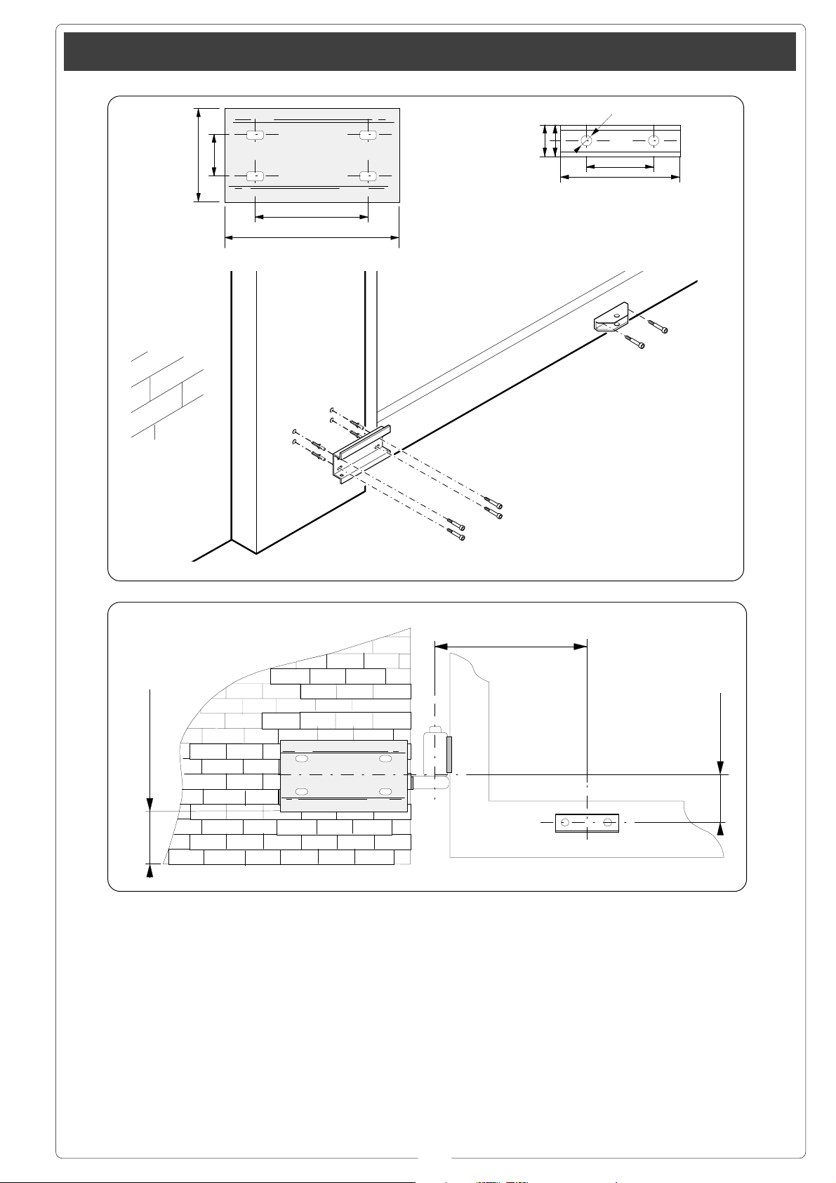
Applicazione della piastra-base e della staffa “A” // Application of the basis-plate and of the stirrup // Application de la
piastre-guide et de l’étrier // Montage der Führungsschienen-Basis und des Steigbügels // Applicacion placa base y estribo “A”
ø6.5
25.5
==
40
96.5
100
60
116
173
Piastra base
Base plate
Plaque de base
Grundplatte
Placa base
ø 14ø 14
ø 14
ø 14ø 14
M8M8
M8
M8M8
Staffa “A”
Bracket “A”
Etrier “A”
Bügel “A”
Estribo “A”
M6M6
M6
M6M6
Vista frontale
Front view
Vue de face
Vorderanssicht
Vista frontal
100 mm min.
- Fissare la piastrabase al pilastro con
viti M8 e tasselli ø14
rispettando la quota
minima di 100 mm.
dalla pavimentazione.
- Fissare la staffa
“A” (con viti M6 o
saldatura) all’anta
del cancello rispettando le quote di C
(vedi tabella a
pagina 4) e 68 mm.
- Use M8 screws and
ø14 screw anchors to
mount the base plate
on the pillar. Be sure
to respect the 100
mm. minimum
distance from the
pavement.
- Attach bracket “A” to
the gate wing (use M6
screws or wlds). Be
sure to respect the
offsets of C (see table
page 4) and 68 mm.
- Fixer la plaque de
base au pilier à
l’aide de vis M8 et
tampons ø14 en
respectant la cote
minimum de 100
mm. du sol.
- Fixer l’étrier “A”
(avec des vis M6 ou
par soudure) sur le
vantail du portail en
respectant les cotes
de C (voir tableau
page 4) et 68 mm.
C
- Die Grundplatte mit
Schrauben M8 und
Dübeln ø14 auf einer
Mindesthöhe von 100
mm. über dem Boden
am Pfeiler befestigen.
- Bügel “A” (mit
Schrauben M6 oder
Schweißung) unter
Einhaltung der Maße
C (sehen Tabelle
Seite 4) und 68 mm.
68 mm
- Fijar la placa base
al pilar con tornillos
M8 y tacos ø14
respetando la cota
mínima de 100 mm.
del suelo.
- Fijar el estribo “A”
(con tornillos M6 o
saldadura) en la
puerta respetando
las cotas de C
(vedas tabla pag. 4)
y 68 mm.
5
Page 6
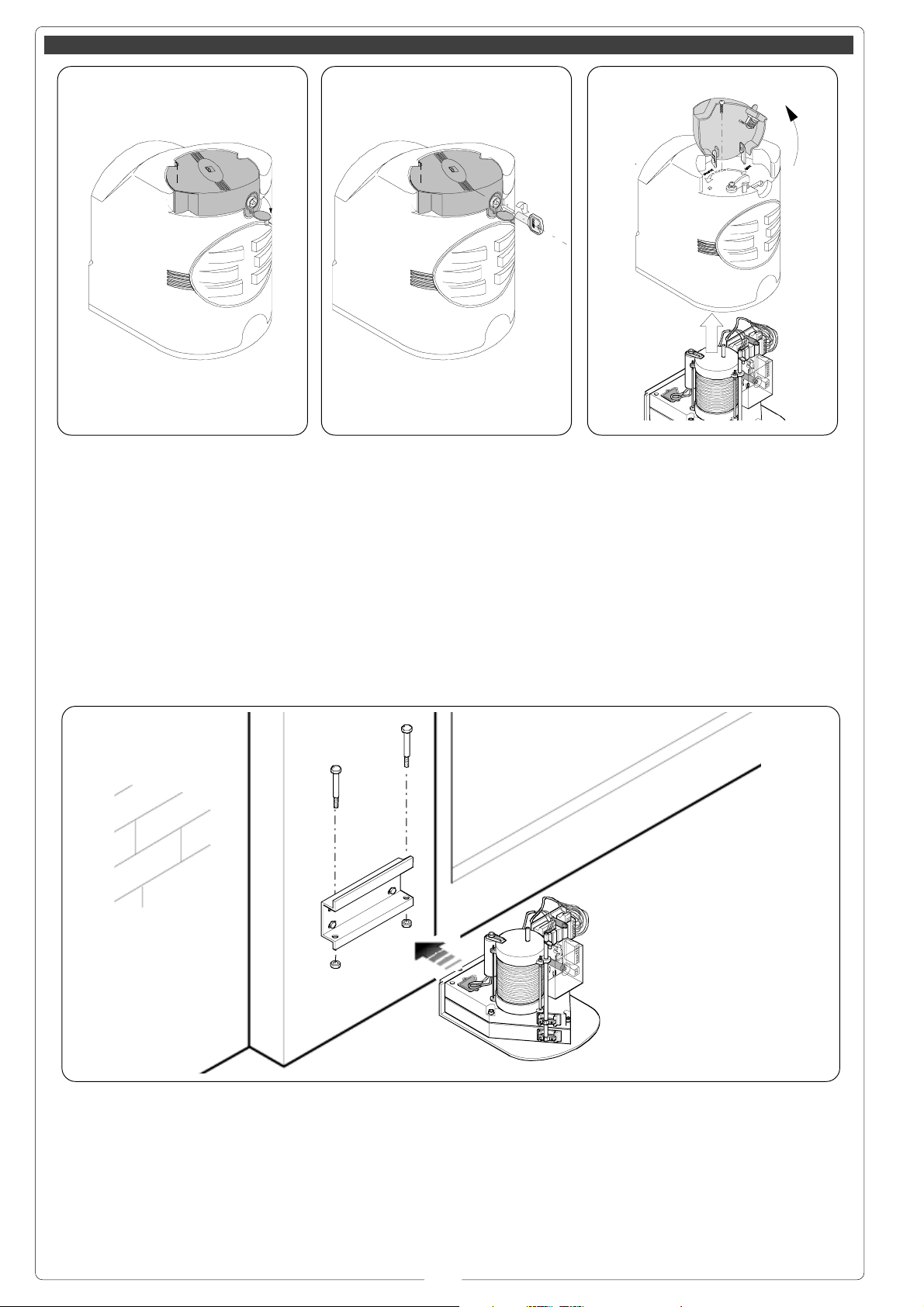
Installazione // Installation // Installation // Installation // Instalación
(1) (2) (3)
(1)
Aprire il tappo
copriserratura (1).
Inserire la chiave
spingerla e ruotarla
in senso orario (2).
Sollevare il coperchio, allentare la vite
Ø 3,9x13 e togliere il
coperchio dal
gruppo
motoriduttore (3).
Open the lock cover
cap (1).
Push the key in and
turn clockwise (2).
Raise the cover,
loosen the Ø 3.9x13
screw and remove the
cover from the
gearmotor unit (3).
Enlever le bouchon
qui recouvre la
serrure (1).
Introduire la clé, la
pousser et la
tourner dans le sens
des aiguilles d’une
montre (2).
Soulever le petit
couvercle, desserrer
la vis Ø 3,9x13 et
enlever le couvercle
du groupe
motoréducteur (3).
Die Schloßabdeckung
(1) aufmachen.
Den Schlüssel ins
Schloß stecken und
im Uhrzeigersinn (2)
drehen.
Die kleine Abdeckung
anheben, die
Schraube Ø 3,9x13
lösen und die
Abdeckung von der
Einheit mit
Getriebemotor (3)
abnehmen.
Ø3,9x13Ø3,9x13
Ø3,9x13
Ø3,9x13Ø3,9x13
Abra el tapón que
cubre la cerradura
(1).
Introduzca la llave,
empújela y gírela hacia la derecha (2).
Levante la tapa, afloje el tornillo Ø 3,9x13
y quite la tapa del
grupo motorreductor
(3).
(4)
Inserire il
motoriduttore nella
piastra-base in
corrispondenza dei 4
fori e fissarlo con le
due viti M8x90 e
relativi dadi M8 in
dotazione (4).
M8x90M8x90
M8x90
M8x90M8x90
M8M8
M8
M8M8
Insert the gearmotor
in the base-plate in
correspondence with
the 4 holes and secure it with the two
M8x90 screws and related M8 nuts provided (4).
Placer le
motoréducteur dans
la plaque de base en
correspondance des
4 trous et le fixer à
l’aide des deux vis
M8x90 et des écrous
M8 correspondants
fournis de série (4).
6
Den Getriebemotor so
auf die Grundplatte
setzen, daß die vier
Löcher übereinstimmen, und mit den
beiden mitgelieferten
Schrauben M8x90
und den dazugehörigen Muttern M8 (4)
befestigen.
Coloque el
motorreductor en la
placa de base, haciendo coincidir los
4 orificios y fíjelo
con los dos tornillos
M8x90 y las tuercas
M8 (4) respectivas
suministradas.
Page 7
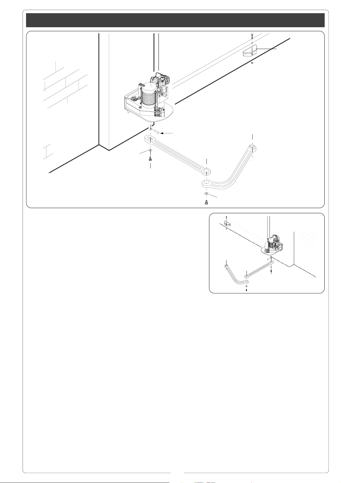
Applicazione del braccio snodato // Application of the articulated arm // Application du bras articulé // Anbringung vom
Gelenkarm // Aplicación del brazo articulado
M12x40M12x40
M12x40
M12x40M12x40
"Staffa A""Staffa A"
"Staffa A"
"Staffa A""Staffa A"
M12M12
M12
M12M12
SpinaSpina
Spina
SpinaSpina
ø 10x40ø 10x40
ø 10x40
ø 10x40ø 10x40
ø 10x35ø 10x35
ø 10x35
ø 10x35ø 10x35
M10x14M10x14
M10x14
M10x14M10x14
- Inserire la spina
Ø10x40 e il braccio
diritto nell’albero del
motoriduttore e fissarlo con la vite
M10x14 e relativa rosetta Ø10x35. Lubrificare il perno del
braccio diritto. Unire
e fissare i due bracci
con la vite M6x10 e
relativa rosetta
Ø6x24. Sbloccare il
motoriduttore e fissare il braccio curvo
alla staffa “A” con la
vite M12x40 ed il relativo dado M12 verificandone il libero
scorrimento. Per applicazione a destra vedere fig. 2.
- Insert the Ø10x40
pin and the straight
arm into the shaft of
the gearmotor and secure it with the
M10x14 screw and related Ø10x35 washer.
Lubricate the pin of
the straight arm. Join
and secure the two
arms with the M6x10
screw and related
Ø6x24 washer. Release the ratiomotor
and fix the curved arm
to the bracket “A” with
the M12x40 screw
and the related M12
nut, checking its free
sliding. For application
on the right-hand side
see fig. 2.
M6x10M6x10
M6x10
M6x10M6x10
- Introduire la
cheville Ø10x40
ainsi que le bras
droit dans l’arbre du
motoréducteur et le
fixer à l’aide de la
vis M10x14 et de la
rondelle Ø10x35
correspondante.
Lubrifier le pivot du
bras droit. Unir et
fixer les deux bras à
l’aide de la vis
M6x10 et de la rondelle Ø6x24
correspondante.
Débloquer le
motoréducteur et
fixer le bras
recourbé à la bride
“A” à l’aide de la vis
M12x40 et de l’écrou
M12 correspondant
en contrôlant s’il
coulisse correctement. Voir la fig. 2
pour l’application à
droite.
7
ø 6x24ø 6x24
ø 6x24
ø 6x24ø 6x24
Den Stecker Ø 10x40
und den geraden Arm
in die Welle vom
Getriebemotor
stecken und mit der
Schraube M10x14
und der dazugehörigen Unterlegscheibe Ø
10x35 befestigen. Den
Zapfen vom geraden
Arm abschmieren. Die
beiden Arme mit der
Schraube M6x10 und
der dazugehörigen
Unterlegscheibe Ø
6x24 verbinden und
befestigen. Den
Getriebemotor
entriegeln und den
gebogenen Arm mit
der Schraube M12x40
und der dazugehörigen Mutter M12 am
Bügel A befestigen.
Dabei darauf achten,
daß der Arm frei
laufen kann. Für die
Anbringung auf der
rechten Seite siehe
Abb. 2.
Fig. 2
- Introduzca el perno
Ø10x40 y el brazo
recto en el árbol del
motorreductor y fíjelo con los tornillos
M10x14 y la arandela respectiva
Ø10x35. Lubrique el
perno del brazo recto. Una y fije los dos
brazos con el tornillo M6x10 y la arandela respectiva
Ø6x24. Desbloquee
el motorreductor y
fije el brazo curvo al
estribo “A” con el
tornillo M12x40 y la
tuerca M12 respectiva, comprobando
que se deslice libremente. Para aplicación a la derecha,
véase fig. 2.
Page 8
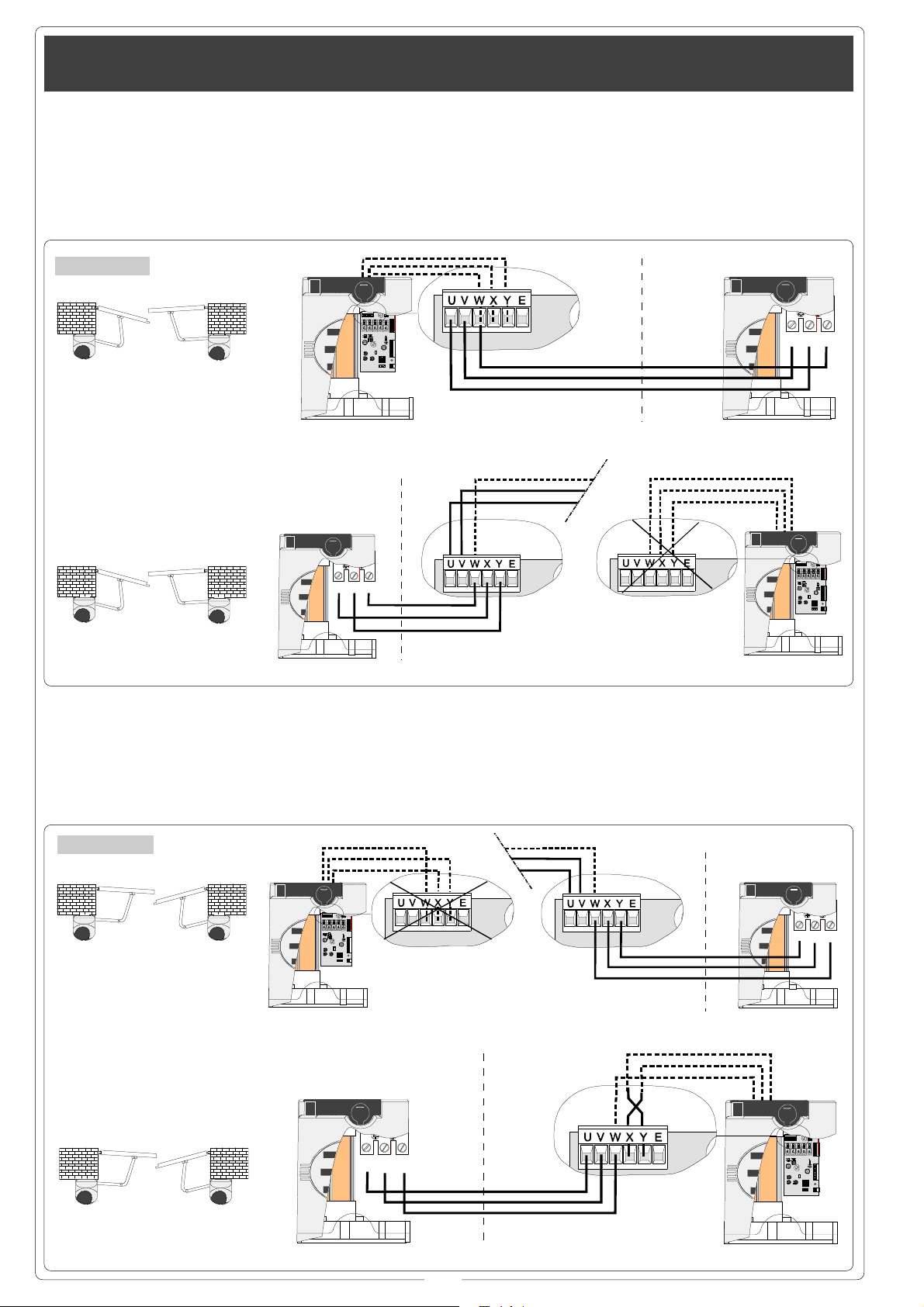
Collegamenti elettrici al quadro ZF1 con cancello a 2 ante // Electrical connections to the ZF1 board with two-door gate
Branchements électriques au tableau ZF1 avec grille à deux portails // Stromanschlüsse an die Schalttafel ZF1 bei einem Tor mit
zwei Torflügeln // Conexiones eléctricas al cuadro ZF1 con cancela de dos hojas
Per cancelli con anta
sinistra ritardata in
chiusura, predisporre il collegamento
come indicato in
figura 1.
Fig/Abb. 1
F 7000
SX
For gates with a delayed-closure lefthand door, prepare
the connection as
shown in figure 1.
F 7001
DX
Prévoir le
branchement comme
indiqué sur la figure
1 pour les grilles
avec portail gauche
retardé en fermeture.
PROG
2143
Für Tore, bei denen
der linke Torflügel
verzögert schließt, die
Anschlüsse wie auf
Abbildung 1
dargestellt
durchführen.
W=W
V=X
U=Y
Para cancelas con
hoja izquierda retardada en el cierre,
realice la conexión
como muestra la figura 1.
VW
U
F 7001F 7000
F 7001
SX
Per cancelli con anta
destra ritardata in
chiusura, predisporre il collegamento
come indicato in
figura 2.
Fig/Abb. 2
F 7000
SX
F 7000
DX
F 7001
For gates with a delayed-closure righthand door, prepare
the connection as
shown in figure 2.
F 7001
DX
VW
U
Prévoir le
branchement
comme indiqué sur
la figure 2 pour les
grilles avec portail
droit retardé en
fermeture.
PROG
2143
W=W
Y=V
X=U
Für Tore, bei denen
der rechte Torflügel
verzögert schließt, die
Anschlüsse wie auf
Abbildung 2
dargestellt
durchführen.
PROG
2143
F 7000
Para cancelas con
hoja derecha retardada en el cierre,
realice la conexión
como muestra la figura 2.
VW
U
F 7001F 7000
F 7001
SX
F 7000
DX
U
F 7001
VW
PROG
2143
F 7000
8
Page 9

Collegamenti elettrici al quadro ZF1 con cancello a un'anta // Electrical connections to the ZF1 board with one-door gate
Branchements électriques au tableau ZF1 avec grille à un portail // Stromanschlüsse an die Schalttafel ZF1 bei einem Tor mit ein
Torflügeln // Conexiones eléctricas al cuadro ZF1 con cancela de uno hoja
Il motoriduttore è
predisposto per
cancelli con anta a
sinistra (figura 1).
Fig/Abb. 1
F 7000
Per cancelli con anta
a destra, predisporre
il collegamento
come indicato in
figura 2.
The gearmotor is
prepared for gates
with a left-hand door
(figure 1).
PROG
2143
For gates with a righthand door, prepare
the connection as
shown in figure 2.
Le motoréducteur
est prévu pour les
grilles avec portail à
gauche (figure 1).
Prévoir le
branchement comme
indiqué sur la figure
2 pour les grilles
avec le portail à
droite.
Der Getriebemotor ist
für Tore mit einem
Torflügel auf der
linken Seite ausgelegt
(Abb. 1).
F 7000
SX
Für Tore mit einem
rechten Torflügel die
Anschlüsse wie auf
Abbildung 2
dargestellt
durchführen.
El motorreductor
está preajustado
para cancelas con
hoja a la izquierda
(figura 1).
Para cancelas con
hoja a la derecha,
realice la conexión
como muestra la figura 2.
Fig/Abb. 2
PROG
2143
F 7000
DX
F 7000
Collegamenti elettrici al quadro elettrico ZA5 // Electrical connections to the ZA5 board // Branchements électriques au tableau ZA5
Stromanschlüsse an die Schalttafel ZA5 // Conexiones eléctricas al cuadro ZA5
Collegamento
elettrico per cancello
con anta a sinistra
(vista interna) fig.1,
con anta a destra
fig.2.
Electrical connection
for gates with lefthand door (internal
view) fig.1, with righthand door fig.2.
Branchement
électrique pour grille
avec portail à
gauche (vue interne)
fig. 1, avec portail à
droite fig. 2.
Die Anschlüsse bei
Toren mit Torflügel auf
der linken Seite
(Innenansicht) wie auf
Abb. 1 durchführen,
für Tore mit Torflügel
auf der rechten Seite
wie auf Abb. 2.
Conexión eléctrica
para cancela con
hoja a izquierda (vista interior) fig.1, con
hoja a derecha fig.2.
Fig/Abb. 1 Fig/Abb. 2
1234
L1L2
T.C.A.
U
F 7001
VW
FUSIBILI LINEA 5A
T.L.
FUSIBILE CENTRALINA 3.15A
12
QUADRO
COMANDO
ZA5
U
VW
F 7001
9
1234
L1L2
T.C.A.
T.L.
FUSIBILE CENTRALINA 3.15A
12
FUSIBILI LINEA 5A
QUADRO
COMANDO
ZA5
Page 10

Collegamenti elettrici al quadro elettrico ZA3 - ZA4 - ZM2 // Electrical connections to the ZA3 - ZA4 - ZM2 board // Branchements
électriques au tableau ZA3 - ZA4 - ZM2 // Stromanschlüsse an die Schalttafel ZA3 - ZA4 - ZM2 // Conexiones eléctricas al cuadro
ZA3 - ZA4 - ZM2
Installare il quadro
comando e procedere ai collegamenti
elettrici come indicato in figura.
Morsettiera quadro comando
Control panel terminal block
Plaque à bornes de l’armoire de commande
Schalttafel-Klemmenleiste
Caja de bornes cuadro de mando
F 7001 F 7001
Install the electrical
control panel and
connect the wiring as
indicated.
VW
U
Installer l’armoire de
commande et
réaliser les
branchements
électriques de la
manière indiquée.
QUADRO COMANDO
T.L. T.C.A.
21 3 45678910
ON
ZE4
FUSIBILE
CENTRAL I NA
2A
FUS.IBILE
LINEA 5A
FUS.IBILE
LINEA 5A
Die Schalttafel
installieren und die
elektrischen
Anschlüsse wie
angegeben ausführen.
Massa -
Ground
- Masse -
Installar el cuadro de
mando y proceder a
las conexiones
eléctricos según lo
indicado.
Erdung
- Tierra
VW
U
Morsettiera 1 motore
1 motor terminal block
Plaque à bornes du moteur 1
Motor 1-Klemmenleiste
Caja de bornes para el 1 motor
Plaque à bornes du moteur 2
Caja de bornes para el 2 motor
Morsettiera 2 motore
2 motor terminal block
Motor 2-Klemmenleiste
Regolazione microinterruttori di stop in chiusura e apertura // Adjusting the microswitches wich stop movement at the end of
closing and opening cycle // Régulation des microinterrupteurs de stop en fermeture et ouverture // Einstellung der
Mikroschalter für Torstop beim Schließen und Öffnen // Regulación microinterruptor de stop en cierre y apertura
Camma superiore
Upper cam
Came supérieure
oberer Nocken
Leva superior
Camma inferiore
Lower cam
Came inférieure
unter Nocken
Leva inferior
Microinterrutore
Microswitches
Microcontacts
Mikroschalter
Microinterruptores
10
Page 11

RR
Regolazioni dei
RR
microinterruttori con
motoriduttore
installato a sinistra
(vista interna).
In apertura: sbloccare il motoriduttore
(1) e portare l’anta
nella posizione di
apertura desiderata
(2). Ruotare la
camma inferiore in
senso orario fino a
far inserire il
microinterruttore e
bloccarla con la vite
centrale (3).
Adjustments of the
microswitches with
gearmotor installed on
the left-hand side
(internal view).
In opening: release
the gearmotor (1) and
allow the door to
reach the opening
position desired (2).
Turn the lower cam
clockwise until the
microswitch is inserted and lock it with
the central screw (3).
Réglage des
microcontacts avec
motoréducteur
installé à gauche
(vue interne).
En ouverture:
débloquer le
motoréducteur (1) et
mettre le portail
dans la position
d’ouverture voulue
(2). Tourner la came
inférieure dans le
sens des aiguilles
d’une montre
jusqu’à ce que le
microcontact
s’enclenche et la
bloquer avec la vis
qui se trouve au
centre (3).
Einstellung der
Mikroschalter bei auf
der linken Seite
installiertem
Getriebemotor
(Innenansicht).
Beim Öffnen: Den
Getriebemotor (1)
entriegeln und den
Torflügel in die
gewünschte
Öffnungsstellung (2)
bringen. Die untere
Nocke im
Uhrzeigersinn drehen,
bis sich der
Mikroschalter einfügt,
und dann mit der
mittleren Schraube (3)
blockieren.
Regulaciones de los
microinterruptores
con motorreductor
instalado a la
izquierda (vista
interior).
En apertura:
desbloquee el
motorreductor (1) y
coloque la hoja en la
posición de apertura
deseada (2). Gire la
leva inferior hacia la
derecha hasta hacer
enganchar el
microinterruptor, y
bloquéela con el tornillo central (3).
(1) (2) (3)
In chiusura: portare
l’anta nella posizione di chiusura
desiderata (4).
Ruotare la camma
superiore in senso
antiorario fino a far
inserire il
microinterruttore e
bloccarla con le due
viti superiori (5).
Manopola
Knob
Poignée
Vierkantwelle
Manilla
In closing: allow the
door to reach the closing position desired
(4). Turn the upper
cam anticlockwise until the microswitch is
inserted and lock it
with the two upper
screws (5).
En fermeture: mettre
le portail dans la
position de
fermeture voulue (4).
Tourner la came
supérieure dans le
sens contraire aux
aiguilles d’une
montre jusqu’à ce
que le microcontact
s’enclenche et la
bloquer avec les
deux vis qui se
Beim Schließen: Den
Torflügel in die
gewünschte
Schließstellung
bringen (4). Die obere
Nocke gegen den
Uhrzeigersinn drehen,
bis sich der
Mikroschalter einfügt,
und dann mit den
beiden oberen
Schrauben (5)
blockieren.
trouvent en haut (5).
Camma inferiore
Lower cam
Came inférieure
unter Nocken
Leva inferior
Microinterrutore
Microswitches
Microcontacts
Mikroschalter
Microinterruptores
Vite centrale
Central screw
Vis centre
Mittleren Schraube
Tornillo central
En cierre: coloque la
hoja en la posición
de cierre deseada
(4). Gire la leva superior hacia la izquierda hasta hacer enganchar el
microinterruptor, y
bloquéela con los
dos tornillos superiores (5).
(4)
(5)
Camma superiore
Came supérieure
oberer Nocken
Leva superior
Microinterrutore
Microswitches
Microcontacts
Mikroschalter
Microinterruptores
11
Upper cam
VV
Viti superiori
VV
Upper screws
Vis haut
Oberen Schrauben
Tornillos superiores
Page 12

Regolazioni dei
microinterruttori con
motoriduttori installati a destra (vista
interna).
In chiusura: sblocca-
re il motoriduttore
(1) e portare l’anta
nella posizione di
chiusura desiderata
(2). Ruotare la
camma inferiore in
senso orario fino a
far inserire il
microinterruttore e
bloccarla con la vite
centrale (3).
Manopola
(1)
Knob
Poignée
Vierkantwelle
Manilla
Adjustments of the
microswitches with
gearmotor installed on
the right-hand side
(internal view).
In closing: unblock the
gearmotor (1) and
allow the door to
reach the closing
position desired (2).
Turn the lower cam
clockwise until the
microswitch is
inserted and lock it
with the central screw
(3).
(2) (3)
Réglage des
microcontacts avec
motoréducteur
installé à droite (vue
interne).
En fermeture:
débloquer le
motoréducteur (1) et
mettre la tige dans la
position de
fermeture voulue (2).
Tourner la came
inférieure dans le
sens des aiguilles
d’une montre
jusqu’à ce que le
microcontact
s’enclenche et la
bloquer avec la vis
qui se trouve au
centre (3).
Einstellung der
Mikroschalter bei auf
der rechten Seite
installiertem
Getriebemotor
(Innenansicht).
Beim Schließen: Den
Getriebemotor (1)
entriegeln und den
Torflügel in die
gewünschte
Schließstellung (2)
bringen. Die untere
Nocke im
Uhrzeigersinn drehen,
bis sich der
Mikroschalter einfügt,
und dann mit der
mittleren Schraube (3)
blockieren.
Camma inferiore
Lower cam
Came inférieure
Unter Nocken
Leva inferior
Regulaciones de los
microinterruptores
con motorreductor
instalado a la
derecha (vista
interior).
En cierre:
desbloquee el
motorreductor (1) y
coloque la hoja en la
posición de cierre
deseada (2). Gire la
leva inferior hacia la
derecha hasta hacer
enganchar el
microinterruptor, y
bloquéela con el tornillo central (3).
In apertura: portare
l’anta nella posizione di apertura
desiderata (4).
Ruotare la camma
superiore in senso
antiorario fino a far
inserire il
microinterruttore e
bloccarla con le due
viti superiori (5).
In opening: allow the
door to reach the
open position desired
(4). Turn the upper
cam anticlockwise until the microswitch is
inserted and lock it
with the two upper
screws (5).
En ouverture: mettre
le portail dans la
position d’ouverture
voulue (4). Tourner la
came supérieure
dans le sens
contraire aux
aiguilles d’une
montre jusqu’à ce
que le microcontact
s’enclenche et la
bloquer avec les
deux vis qui se
trouvent en haut (5).
(4) (5)
Beim Öffnen: Den
Torflügel in die
gewünschte
Öffnungsstellung
bringen (4). Die obere
Nocke gegen den
Uhrzeigersinn drehen,
bis sich der
Mikroschalter einfügt,
und dann mit den
beiden oberen
Schrauben (5)
blockieren.
Camma superiore
Upper cam
Came supérieure
oberer Nocken
Leva superior
Microinterrutore
Microswitches
Microcontacts
Mikroschalter
Microinterruptores
Microinterrutore
Microswitches
Microcontacts
Mikroschalter
Microinterruptores
Vite centrale
Central screw
Vis centre
Mittleren Schraube
Tornillo central
En apertura: coloque
la hoja en la posición de apertura deseada (4). Gire la
leva superior hacia
la izquierda hasta
hacer enganchar el
microinterruptor, y
bloquéela con los
dos tornillos superiores (5).
Viti superiori
Upper screws
Vis haut
Oberen Schrauben
Tornillos superiores
12
Page 13

Montaggio coperchio // Cover Assembly // Montage du couvercle // Montage der Abdeckung // Montaje de la tapa
Dopo aver ultimato
le operazioni di montaggio, collegamenti
elettrici e regolazioni, inserire il coperchio fissandolo
con la vite Ø3,9x13.
Inserire la manopola
di sblocco in posizione "LOCK" e fissarla.
After completing the
assembly operations,
electrical connections
and adjustments, insert the lid and secure
it with the Ø3.9x13
screw. Insert the release knob in “LOCK”
position and secure it.
ø 3,9x13ø 3,9x13
ø 3,9x13
ø 3,9x13ø 3,9x13
Placer le couvercle
en le fixant avec la
vis Ø3,9x13 après
avoir terminé les
opérations de
montage, les
branchements
électriques et le
réglage. Mettre le
bouton de déblocage
sur “LOCK” et le fixer.
Nach Beendigung
der Montage und
Durchführung der
Stromanschlüsse
und Einstellungen
die Abdeckung
einsetzen und mit
der Schraube
Ø3,9x13 befestigen.
Den
Entriegelungsgriff auf
“LOCK” stellen und
blockieren.
Tras haber concluido los trabajos de
montaje, conexiones
eléctricas y regulaciones, introduzca la
tapa fijándola con el
tornillo Ø3,9x13. Coloque la manecilla
de desbloqueo en
poción “LOCK” y fíjela.
13
Page 14

Accessori opzionali // Optional accessories // Accessoires sur demande // Zubehör auf Anfrage // Accesorios opcionales
H3000 - Dispositivo
di sblocco a cordino
(L = 5 m.) completo
di contenitore di sicurezza, manopola
di sblocco e pulsante.
NOTA: evitare di formare con il cordino
di sblocco angoli
acuti (1) o retti (2).
H3000 - Disposal of
connecting-release (L
= 5 m.) complete of
surety-container,
release hand grip and
push-button.
NOTE: avoid to create
any acute or right
angle with the
release-connector.
H3000 - Mechanism
de débloquage
coordonné (L = 5 m.)
complet de récipient
de sureté, poignée
de débloquage et
bouton.
NOTE: on ne doit
pas créer d’ngles
droits ou aigus avec
le débloquage.
Contenitore di sicurezza
Protective casing
Boítier de sécurité
Schutzkasten
Contenidor de seguridad
H3000- Aufhebungsvorrichtung (L = 5 m.)
mit Sicherheitsbehälter, Griff und
Knöpfchen.
ACHTUNG: man
muss keinen rechten
oder spitzen Winkel
bilden.
H3000 - Dispositivo
de desbloqueo a
cuerda (L= 5 m.), con
caja de seguridad,
manilla de
desbloqueo y botón.
NOTA: evitar formar
angulos rectos o
agudos con la
cuerda.
H 3000
Molla
Spring
Ressort
Feder
Muelle
Astina
Small bar
Tige
Stange
Varilla
Cordino
Cord
Cordelette
Bowdenzug
Cuerda
14
Page 15

ITALIANO
DESCRIZIONE TECNICA QUADRO COMANDO ZF1
Descrizione
La scheda comando ZF1 è adatta al
comando di automazioni a 230V
monofase, per motoriduttori serie FAST
(portoni a battente residenziali).
La scheda deve essere alimentata a
230V (a.c.) sui morsetti L1 e L2, ed é
protetta in ingresso con un fusibile da
5A, mentre gli accessori a bassa tensione (24V) sono protetti con fusibile da
3.15A.
La potenza complessiva degli accessori
(24V) non deve superare i 20W.
Sicurezza
Le fotocellule possono essere collegate
e predisposte per:
Riapertura
fotocellule rilevando un ostacolo durante la fase di chiusura del cancello, provocano l'inversione di marcia fino alla completa apertura;
Stop totale
con l'esclusione del ciclo di chiusura
automatica, per riprendere il movimento
del cancello, agire sulla pulsantiera o sul
in fase di chiusura (2-C1), le
(1-2), arresto del cancello
radiocomando;
Accessori opzionali
-
Elettroserratura
Lampada spia cancello aperto
max.). Lampada che segnala la posizione di apertura del cancello, si spegne
quando il cancello è a fine tempo lavoro
chiude (5-10).
Altre funzioni
-
Chiusura automatica.
di chiusura automatica si autoalimenta a
fine tempo lavoro apre. Il tempo prefissato regolabile, è in ogni modo subordinato dall'intervento di eventuali accessori di sicurezza e si esclude dopo un
intervento di "stop" o in mancanza d'energia elettrica;
"Uomo presente"
cancello mantenendo premuto il pulsante (esclude la funzione del radiocomando). Si abilita quando il trimmer T.L. è
regolato al minimo.
12V (ES-ES);
(3W
Il temporizzatore
. Funzionamento del
Regolazioni
- Tempo chiusura automatica;
- Tempo ritardo chiusura del 2° motore;
- Tempo lavoro.
ATTENZIONE: prima di intervenire
all'interno dell'apparecchiatura,
togliere la tensione di linea
ENGLISH
Description
The ZF1 control board is suitable for controlling 230V single-phase automated
gates, for FAST series ratiomotors (residential swing gates).
The board must be powered at 230V
(a.c.) on the L1 and L2 terminals, and
the inlet is protected with a 5A fuse, while
the low voltage (24V) accessories are
protected with a 3.15A fuse.
The accessorie's total capacity (24V)
should not exceed 20W.
Safety
Photocells can be connected to abtain:
Re-opening
the photocells identify an obstacle while
the gate is closing, they will reverse the
direction of movement until the gate is
completely open;
Total stop
movement without automatic closing, a
pushbutton or radio remote control must
be actuated to resume movement.
during closure (2-C1), if
(1-2), shutdown of gate
TECHNICAL DESCRIPTION ZF1 CONTROL PANEL
Optional accessories
-
12V
Electric lock
Open gate pilot lamp
that signals the gate is open, turns off
when the time fixed for the gate’s closing
has elapsed (10-5).
Other functions
Automatic closing.
closing timer is automatically activated
at the end of the opening cycle. The
preset, adjustable automatic closing time
is automatically interrupted by the
activation of any safety system, and is
deactivated after a STOP command or in
case of power failure;
"Operator present"
when the pushbutton is held down (the
radio remote control system is
deactivated). It is activated when the
T.L. trimmer is set to the minimun.
(ES-ES);
(3W max.). Lamp
The automatic
. Gate operates only
Adjustments
- Automatic closure time;
- Delay in closing of the M2 motor;
- Operating time.
IMPORTANT: Shut off the mains
power before servicing the inside
of the unit.
15
Page 16

FRANÇAIS
DESCRIPTION TECHNIQUE ARMOIRE DE COMMANDE ZF1
Description
La carte de commande ZF1 est indiquée
pour commander les automatismes à
230V monophasés, pour les
motoréducteurs série FAST (portes à
battants d’immeubles).
La carte doit être alimentée à 230V (c.a.)
sur les bornes L1 et L2 et est protégée à
l’entrée par un fusible de 5A, tandis que
les accessoires en basse tension (24V)
sont protégés par un fusible de 3.15A.
La puissance totale des accessoires
(24V) ne doit pas dépasser 20W.
Sécurité
Il est possible de brancher des
photocellules et de les programmer pour:
Réouverture
C1), les cellules photoélectriques
provoquent l'inversion de marche jusqu'à
l'ouverture complète si elles relèvent un
obstacle durant la phase de fermeture
du portail;
Stop total
désactivation d’un éventuel cycle de
fermeture automatique; pour activer de
nouveau le mouvement, il faut agir sur
en phase de fermeture (2-
(1-2), arrêt du portail et
les boutons-poussoirs ou sur la radiocommande.
Accessoires en option
-
Serrure électrique
Voyant grille ouverte
qui signale la position d’ouverture de la
grille et s’éteint quand la grille a fini de
se refermer (10-5).
Autres fonctions
-
Fermeture automatique.
risateur de fermeture automatique est
autoalimenté à la fin du temps de la
course en ouverture. Le temps réglable
est programmé, cependant, il est
subordonné à l’intervention d’éventuels
accessoires de sécurité et il est exclu
après une intervention de “stop” ou en
cas de coupure de courant;
Fonction “homme mort”
tionnement du portail en maintenant
appuyé le bouton-poussoir (exclut la
fonction de la radiocommande).Il s'active
quand le compensateur T.L. est réglé au
minimum.
12V (ES-ES);
(3W max.). Voyant
Le tempo-
. Fonc-
Reglages
- Temps de fermeture automatique;
- Retard fermeture moteur 2;
- Temps de fonctionnement.
ATTENTION: avant d'intervenir à
l'intérieur de l'appareillage, couper
la tension de ligne
DEUTSCH
Beschreibung
Die Steuerkarte ZF1 eignet sich zur
Steuerung von 230 V EinphasenAutomatiksystemen sowie für Getriebemotoren der Serie FAST (Flügeltüren für
Wohnhäuser).
Die Karte muß über die Klemmen L1 und
L2 mit 230 V AC gespeist werden und
ist am Eingang durch 5 A Sicherungen
geschützt.
Das Niedrigspannungszubehör (24 V)
dagegen ist durch 3,15 A Sicherungen
geschützt.
Die Gesamtleistung der Zubehörteile
(24V) darf 20W nicht übersteigen.
Sicherheitsvorrichtungen
Die Lichtschranken können für folgende
Funktionen angeschlossen bzw.
vorbereitet werden:
Wiederöffnen
die Lichtschranken ermitteln ein
Hindernis während des schließens vom
Tor und lösen die Umkehr der
Laufrichtung vom Tor aus, bis dieses
wieder vollständig geöffnet ist;
beim Schließen (2-C1),
TECHNISCHE BESCHREIBUNG SCHALTTAFEL ZF1
Totalstop
Tores mit Ausschluß eventueller
Schließautomatik: Fortsetzung des
Torlaufs über Drucktaster- bzw. Funksendersteuerung.
Extrazubehör
Elektroschloß
-
Kontrollleuchte Tor offen
Kontrollleuchte zeigt an, daß das Tor
offen ist und schaltete sich ab, wenn das
Tor nach Arbeitsende geschlossen wird
(10-5).
Andere wahlfunktionen
Schließautomatik
automatik-Zeischalter speist sich beim
Öffnen am Ende der Torlaufzeit selbst .
Die voreingestellte Zeit ist auf jeden Fall
immer dem Eingriff eventueller
Sicherheitsvorrichtungen untergeordnet
und schließt sich nach einem “Stop”Eingriff bzw. bei Stromausfall selbst aus;
Funktion “Bedienung vom Steuerpult”
Torbetrieb durch Drucktasterbetätigung
(1-2), sofortiger Stillstand des
12V (ES-ES);
(3W max.). Die
. Der Schließ-
(Funkfernsteuerung ausgeschlossen).
Wird dann eingeschaltet, wenn der
Trimmer T.L. auf das Minimum gestellt
ist.
Einstellungen
- Zeit für das automatische Schließen;
- Schließverzögerung Motor 2;
- Laufzeit.
ACHTUNG: Das Gerät vor Eingriffen
.
im inneren spannungsfrei schalten
16
Page 17

ESPAÑOL
DESCRIPCIÓN TÉCNICA CUADRO DE MANDO ZF1
Descripción
La tarjeta de mando ZF1 es idónea al
accionamiento de automatizaciones de
230V monofásica para motorreductores
serie FAST (puertas de batiente
residenciales).
La tarjeta se debe conectar a 230V (c.a.)
en los bornes L1 y L2, y está protegida a
la entrada con un fusible de 5A, mientras
que los accesorios de baja tensión (24V)
están protegidos con un fusible de 3,15A.
La potencia total de los accesorios (24V)
no tiene que superar los 20W.
Seguridad
Las fotocélulas pueden estar conectadas y predispuestas para:
Reapertura
-
en la fase de cierre (2-C1),
las fotocélulas detectan un obstáculo durante el cierre de la puerta, provocando
la inversión de marcha hasta la apertura completa;
-
Parada total
(1-2), parada de la puerta
excluyendo el posible ciclo de cierre
automático; para reactivar el movimiento
es preciso actuar en el teclado o en el
mando a distancia.
Accesorios opcionales
-
Cerradura eléctrica
Indicador luminoso cancela abierta
-
12V (ES-ES);
(3W max.). Indicador luminoso que indica la posición de apertura de la
cancela; se apaga cuando la cancela
llega al final del tiempo de cierre (10-5).
Otras funciónes
-
Cierre automático
. El temporizador de
cierre automático se autoalimenta en finde-tiempo carrera en fase de apertura.
El tiempo prefijado regulable, sin
embargo, está subordinado a la
intervención de posibles accesorios de
seguridad y se excluye después de una
intervención de parada o en caso de falta
de energía eléctrica;
Función a "hombre presente"
-
. Fun-
cionamiento de la puerta manteniendo
pulsada la tecla (excluye la función del
mando a distancia). Se activa cuando el
trimmer T.L. está regulado en el mínimo.
Regulaciones
- Tiempo de cierre automático;
- Retraso cierre motor 2;
- Tiempo trabajo.
ATENCION: antes de actuar dentro
del aparado, quitar la tensión de
línea
Scheda base // Motherboard // Carte base // Grundplatine // Tarjeta base
COMPONENTI PRINCIPALI
1 Morsettiere di collegamento
I GB
2 Fusibile di linea 5A
3 Fusibile accessori 3.15A
4 Pulsante memorizzazione codice
radio
5 Trimmer di regolazione ritardo del
2° motore
6 Trimmer di regolazione tempo
lavoro
7 Trimmer di regolazione tempo di
chiusura automatica
8 Selettore funzioni a 2 dip (vedi pag.
19)
9 Innesto scheda radiofrequenza
(vedi tabella pagina 20)
10 LED segnalazione
PRINCIPAUX COMPOSANTS
1 Plaque à bornes de connexion
F D E
2 Fusible de ligne 5A
3 Fusible accessoires 3.15A
4 Bouton-poussoir mémorisation code
radio
5 Trimmer de réglage retard
fermeture moteur 2
6 Trimmer de réglage temps de
fonctionnement
7 Trimmer de réglage fermeture
automatique
8 Selecteur de fonctions à 2
interrupteurs à positions multiples
(voir page 19)
9 Branchement carte radiofréquence
AF (voir tableau page 20)
10 LED de signalisation
MAIN COMPONENTES
1 Terminal block for external
conections
2 Line fuse, 5A
3 Fuse on accessory power line,
3.15A
4 Radio-code save button
5 Trimmer for adjustment delay on
closing cycle - motor 2
6 Trimmer for adjustment operating
time
7 Trimmer for adjustment automatic
closing
8 2-dip function switch (see pag. 19)
9 Socket AF radiofrequency board
(see table page 20)
10 Signal LED
HAUPTKOMPONENTEN
1 AnschlußKlemmenleiste
2 Hauptsicherung 5A
3 Zubehör-Sicherung 3.15A
4 Knöpfe zum Abspeicher der
Radiocode
5 Trimmer zur Einstellung
Schließverzögerung Motor 2
6 Trimmer zur Einstellung Laufzeit
7 Trimmer zur Einstellung der
Schließautomatik
8 Wählschalter für Funktionen mit 2
Dip (sehen Seite 19)
9 Steckanschluß Funkfrequenze-
Platine AF (sehen Tabelle Seite 20)
10 LED Kontrolleuchte zur Anzeige
22
2
22
33
3
33
44
4
44
55
5
55
66
6
66
PRINCIPALES COMPONENTES
PROG
21
77
88
7
77
99
8
9
88
99
1010
10
1010
11
1
11
1 Caja de bornes para las
conexiónes
2 Fusible de línea 5A
3 Fusible accesorios 3.15A
4 Tecla de memorización del código
radio
5 Trimmer de regulación retraso
cierre motor 2
6 Trimmer de regulación tiempo
trabajo
7 Trimmer de regulación tiempo
cierre automático
8 Selector de funciones con 2 dip
(vedas pag. 19)
9 Conexión tarjeta radiofrecuencia
AF (vedas tabla pag. 20)
10 LED Kontrolleuchte zur Anzeige
17
Page 18

Collegamenti elettrici // Electrical connections // Branchements électriques // Elekrische anschlüsse // Conexiones eléctricas
UVWXY EL1 L2 7 2C1 1110 ES5ES1
Alimentazione 230V (a.c.)
L1
L2
U
W
V
X
W
Y
230V (a.c.) power input
Alimentation 230V (c.a.)
Stromversorgung 230V (Wechselstrom)
Alimentación 230V (a.c.)
Motore “1” monofase 230V (a.c.) ritardato in apertura
Motor “1” single-phase 230V (a.c.) delayed opening
Moteur “1” monophasé 230V (c.a.) retardé en ouverture
Motor “1” 230V (Wechselstrom) Einphasenmotor mit Verzögerung beim Öffnen
Motor “1” monofásico 230V (a.c.) retardado durante la apertura
Motore “2” monofase 230V (a.c.) ritardato in chiusura
Motor “2” single-phase 230V (a.c.) delayed closure
Moteur “2” monophasé 230V (a.c.) retardé en fermeture
Motor “2” 230V (Wechselstrom) Einphasenmotor mit Verzögerung beim Schließen
Motor “2” monofásico 230V (a.c.) retardado durante el cierre
W
E
5
10
2
7
2
C1
Uscita 230V (a.c.) in movimento (es. lampeggiatore - max. 25W)
230V (a.c.) output in motion (e.g. flashing light - max. 25W)
Sortie 230V (c.a.) en mouvement (ex. branchement clignotant - max. 25W)
Ausgang 230V (Wechselstrom) in Bewegung (z.B. Blinker-Anschluß - max. 25W)
Salida de 230V (a.c.) en movimento (p.ej. conexión lámpara intermitente - max. 25W)
Lampada spia (24V-3W max.) "cancello aperto"
(24V-3W max.) "gate-opened" signal lamp
Lampe-témoin (24V-3W max.) "portail ouverture"
Signallampe (24V-3W max.) "Tor Öffnen"
Lámpara indicadora (24V-3W max.) "puerta abierta"
Contatto (N.O.) radio e/o pulsante per comando (vedi dip 2)
(N.O.) contact radio and/or button for control (see dip 2)
Contact (N.O.) radio et/ou poussoir pour commande (voir dip 2)
Funkkontakt (Arbeitskontakt) und/oder Taste Steuerart (sehen dip2)
Contacto (N.O.) radio y/o pulsador para mando (mirar dip 2)
Contatto (N.C.) di «riapertura durante la chiusura»
Contact (N.C.) for «re-opening during the closing»
Contact (N.F.) de «réouverture pendant la fermeture»
Kontakt (Ruhekontakt) «Wiederöffnen beim Schliessen»
Contacto (N.C.) para la «apertura en la fase de cierre»
1
2
10
11
Pulsante stop (N.C.)
Pushbutton stop (N.C.)
Bouton-poussoir arrêt (N.F.)
Stop-Taste (N.C.)
Pulsador de stop (N.C.)
Alimentazione accessori 24V (a.c.) max. 20W
24V (a.c.) Powering accessories max. 20W
Alimentation accessoires 24V (c.a.) max. 20W
Zubehörspeisung 24V (Wechselstrom) max. 20W
Alimentación accesoios 24V (a.c.) max. 20W
18
Page 19

ES
ES
Collegamento elettroserratura (12V-15W max.)
(12V-15W max.) connection for electrically-actuated lock
Connexion serrure électrique (12V-15W max.)
Anschluß Elektroschloß (12V-15W max.)
Conexión electrocerradura (12V-15W max.)
Collegamento antenna
Antenna connection
Connexion antenne
Antennenanschluß
Conexión antena
Selezioni funzioni // Function slections // Sélections fonction // Funktionswahl // Selecciónes función
I
1 ON Chiusura automatica attivata; (1 OFF - disattivata)
2 ON "Apre-stop-chiude-stop” con pulsante (2-7) e
radiocomando (scheda AF inserita) attivato;
2 OFF "Apre-chiude” con pulsante (2-7) e radiocomando
(scheda AF inserita) attivato;
GB
1 ON Automatic closing enabled; (1 OFF - disabled)
2 ON "Open-stop-close-stop" function with button (2-7)
and radio control (AF board inserted) enabled;
2 OFF "Open-close" function with button (2-7) and radio
control (AF board inserted) enabled;
D
PROG
21
F
ON
21
OFF
1 ON Fermeture automatique activé; (1 OFF - éteinte)
2 ON "Ouvre-stop-ferme-stop" avec bouton (2-7) et
commande-radio (carte AF insérée) activé;
2 OFF "Ouvre-ferme" avec bouton (2-7) et commande-
radio (carte AF insérée) activé;
E
1 ON Schließautomatik zugeschaltet; (1 OFF -
ausgeschlossen)
2 ON "Öffnen-Stop-Schließen-Stop" mit Druckknopf (2-7)
und Fernsteuerung (Karte AF eingesteckt)
zugeschaltet;
2 OFF "Öffnen-Schließen" mit Druckknopf (2-7) und
Fernsteuerung (Karte AF eingesteckt)
zugeschaltet;
1 ON Cierre automático activado; (1 OFF - desactivado)
2 ON "Abrir-parada-cerrar-parada" con botón (2-7) y
radiocontrol (tarjeta AF conectada) activado;
2 OFF "Abrir-cerrar" con botón (2-7) y radiocontrol (tarjeta
AF conectada) activado;
19
Page 20

Regolazioni // Adjustments // Réglage // Einstellung // Régulación
I
Trimmer T.R.2M.
= Regolazione tempo ritardo del 2°
motore da un minimo di 1 secondo a un massimo di 10
secondi.
Trimmer T.L.
= Regolazione tempo lavoro da un minimo di
15 secondi a un massimo di 120 secondi.
(Nota: regolando al minimo il tempo lavoro si abilita la
funzione «uomo presente»).
Trimmer T.C.A.
= Regolazione tempo di chiusura automati-
ca da un minimo di 0 secondi a un massimo di 120 secondi.
GB
Trimmer T.R.2M.
= Adjustment delay during closure of 2nd
motor, min.1”, max.10”.
Trimmer T.L.
= Adjusts of operating time, min.15”,
max.120”.
(Note: the "operator present" function is activated by setting
the operating time to the minimum).
Trimmer T.C.A.
= Adjusts automatic closing time, min.0”,
max.120”.
D
Trimmer T.R.2.M.
= Einstellung der Verzögerungszeit vom
2. Motor beim Schließen (min. 1”, max. 10”).
Trimmer T.L.
= Laufzeit mit mindestens 15“ und höchstens
120” eingestellt werden kann.
(Hinweis: Wenn die Betriebsdauer auf ein Minimum gestellt
wird, wird die Funktion "Bedienung vom Steuerpult"
eingeschaltet).
Trimmer T.C.A.
= Timer, auf dem die Verzögerung für das
automatische Schließen mit mindestens 0” und höchstens
120” eingestellt werden kann.
Programmazione del radiocomando // Programming the remote control // Programmation de la commande radio //
Programmierung der Funkfernsteuerung // Programmación del mando a distancia
T.R.2M
PROG
2143
T.L.
F
Trimmer T.R.2M.
T.C.A.
REGOLAZION E TRIMMERS
TRIMMERS ADJUSTMENT
RÉGLAGE TRIMMERS
EINTELLUNG TRIMMERS
REGULACIÓN TRIMMERS
= Réglage retard en fermeture 2° moteur,
min. 1”, max. 10”.
Trimmer T.L.
= Réglage du temps de fonctionnement, min.
15”, max. 120”.
(Note: la fonction "homme mort" s'active en réglant le
temps de fonctionnement au minimum).
Trimmer T.C.A.
= Réglage du temps de fermeture
automatique (min. 0”, max. 120”).
E
Trimmer T.R.2.M.
= Régulación del retardo durante el
cierre del 2° motor (min. 1”, max. 10”).
Trimmer T.L.
= Régulación tiempo de trabajo (min. 15”,
max. 120”).
(Nota: regulando en el mínimo el tiempo de trabajo, se
activa la función "hombre presente").
Trimmer T.C.A.
= Régulación cierre automático (min. 0”,
max. 120”).
ITALIANO
PROCEDURA
A. inserire una sche-
da AF.
B. codificare il/i tra-
smettitore/i.
C. memorizzare la
codifica sulla
scheda base.
A
La schedina AF deve
essere inserita
OBBLIGATORIAMENTE
in assenza di tensione.
ENGLISH
PROCEDURE
A. insert an
AF card.
B. encode
transmitter/s.
C. store code in the
motherboard.
INSERIMENTO SCHEDA AF -
Frequenza / MHz
Frequency / MHz
Frequence / MHz
Frequenz / MHz
Frecuencia / MHz
FM 26.995 AF130 TFM
FM 30.900 AF150 TFM
AM 26.995 AF26 TOP
AM 30.900 AF30 TOP
AM 433.92
EINSTECKEN DER KARTE AF-
Scheda radiofrequenza
Radiofrequency board
Carte radiofréquence
Funkfrequenz-Platine
Tarjeta radiofrecuencia
AF43S / AF43SM TAM / TOP
AF43SR AT OMO
FRANÇAIS
PROCEDURE
A. placer une carte
AF.
B. codifier le/s
émetteur/s.
C. mémoriser la
codification sur la
carte base.
AF BOARD INSERTION
MONTAJE DE LA TARJETA AF
DEUTSCH
PROZEDUR
A. Stecken Sie eine
Karte AF.
B. Codieren Sie den/
die Sender.
C. Speichern Sie die
Codierung auf der
Grundplatine.
- INSTALLATION DE LA CARTE AF
Trasmettitore
Transmitter
Emetteur
Funksender
Transmis or
SCHEDA BASE
MOTHERBOARD
CARTE DE BASE
TARJETA BASE
BASISKARTE
ESPAÑOL
PROCEDIMIENTO
A. introducir una
tarjeta AF.
B. codificar el/los
transmisor/es.
C. memorizar la
codificación en la
tarjeta base.
21
SCHEDA "AF"
"AF" BOARD
CARTE "AF"
KARTE «AF»
TARJETA «AF»
The AF board should
ALWAYS be inserted
when the power is off.
La carte AF doit
OBLIGATOIREMENT être
branchée en l’absence de
tension.
Vor Einschieben der Karte die
Stromzufuhr UNBEDINGT
abschalten.
20
La tarjeta AF se debe montar
OBLIGATORIAMENTE en caso
de falta de corriente.
Page 21

B
CODIFICA TRASMETTITORI -
CODIERUNG DER SENDER -
TOP
QUARZATI
TRANSMITTER ENCODING
- QUARTZ
CODIFICACIÓN TRANSMISORES
- AU QUARTZ
- QUARTZGENAUE
- CODIFICATION DES EMETTEURS
- CUARZO
PROCEDURA COMUNE DI CODIFICA
T262M-T264M-T2622M
T302M-T304M-T3022M
1.segnare un codice (anche per archivio)
2.inserire jumper codifica J
3.memorizzarlo
4.disinserire jumper J
ANLEITUNGEN ZUR CODIERUNG
T262M-T264M-T2622M
T302M-T304M-T3022M
1.Ordnen Sie einen Code zu (auch für das
Archiv).
2.Schalten Sie den Codierungs-Jumper J ein.
3.Speichern Sie den Code.
4.Schalten Sie den Jumper J wieder aus.
PROCEDIMIENTO COMÚN DE CODIFICACIÓN
T262M-T264M-T2622M
T302M-T304M-T3022M
1.marcar un código (también para el
archivo)
2.conectar un jumper codificación J
3.registrar el código
4.desconectar jumper J
T2622M - T3022M
1° codice/
Code
P1 P2
code/
/código
code/
J
STANDARD ENCODING PROCEDURE
T262M-T264M-T2622M
T302M-T304M-T3022M
1.assign a code (also on file)
2.connect encoding jumper J
3.register code
4.disconnect jumper J
codice/
1.
codice
P1
P2
3.
premere in sequenza P1 o P2 per registrare il
codice; al decimo impulso un doppio suono
confermerà l'avvenuta registrazione
Press P1 or P2 in sequence in order to register
the code; at the tenth pulse, a double beep will
confirm that registration has occurred
appuyer en séquence sur P1 ou P2 pour
mémoriser le code; à la dixième impulsion, une
double sonnerie confirme que le code a été
mémorisé
Drücken Sie nacheinander P1 oder P2, um den
Code zu speichern. Nach dem zehnten Impuls
signalisiert ein doppelter Piepton, daß der Code
gespeichert worden ist.
oprimir repetidamente P1 ó P2 para registrar el
código; con el décimo impulso un doble sonido
señalará que el registro se ha efectuado.
/codice/
codice
PROCEDURE COMMUNE DE CODIFICATION
T262M-T264M-T2622M
T302M-T304M-T3022M
1.taper un code (également pour les
archives)
2.placer un cavalier de codification J
3.mémoriser le code
4.enlever le cavalier J
/codice
OFF
ON
P1=OFF
2.
J
P2=ON
4.
J
2° codice/
P1
P2
J
code/
code/
T264M - T304M
P1=CH1 - P2=CH2
P3=CH3 - P4=CH4
P1 P2
P3 P4
Code
P1=CH1
P2=CH2
/código
J
OFF
ON
P3=CH1
P4=CH2
P1 P2
fig. A
T262M - T302M
La prima codifica deve essere effettuata mantenendo i jumper
posizionati per i canali 1 e 2 come da fig. A; per eventuali e successive impostazioni su canali diversi vedi fig. B
The first encoding operation must be carried out whilst keeping the
J
jumpers positioned for channels 1 and 2 as per fig. A; see fig. B for
any subsequent settings on different channels.
La première codification doit être effectuée en maintenant les
cavaliers en position pour les canaux 1 et 2, comme d'après la fig.
A; pour des saisies successives éventuelles sur des canaux
différents, voir fig. B
Für die erste Codierung muß der Jumper auf den Kanälen 1 und 2
positioniert bleiben (siehe Abb. A). Für eventuelle weitere oder
spätere Einstellungen auf anderen Kanälen halten Sie sich bitte an
Abb. B.
La primera codificación tiene que efectuarse manteniendo los
jumper conectados para los canales 1 y 2 como se ilustra en la fig.
A; para planteamientos posteriores en canales distintos ver la fig. B
fig. B
P1=CH1 - P2=CH3
P1=CH1
P2=CH2
P1=CH3 - P2=CH2
21
P1=CH1 - P2=CH4
P1=CH3 - P2=CH4
Page 22

P1 P2
D
1 2 3 4
1 2 3 4 5 6 7 8 9 10
ATOMO
AT01 - AT02 - AT04
vedi foglio istruzioni inserito nella confezione
della scheda AF43SR
see instruction sheet inside the pack of AF43SR circuit card
voir les instructions qui se trouve dans l'emballage
de la carte AF43SR
Siehe Anleitungen, die der Packung beiliegen der Platine AF43SR
ver hoja de instrucciones adjunta en el embalaje
de la tarjeta AF43SR
T432M - T312M
impostare il codice sul dip-switch C e il canale su D (P1=CH1 e P2=CH2, impostazione di
default)
set the code to dip-switch C and channel to D (P1=CH1 and P2=CH2, default setting)
saisir le code sur le commutateur dip C et le canal sur D (P1=CH1 et P2=CH2, saisie de
défaut)
Stellen Sie den Code auf den Dip-Switch C und den Kanal auf D (P1=CH1 und P2=CH2;
Grundeinstellung).
plantear el código en el dip-switch C y el canal en D (P1=CH1 y P2=CH2, planteamiento
por defecto)
P1
1 2 3 4 1 2 3 4 1 2 3 41 2 3 4
CH1 CH2 CH3
CH4
C
P2
1 2 3 4 1 2 3 4 1 2 3 4 1 2 3 4
CH1 CH2 CH3
CH4
P1 P2
P3 P4
P1=CH1
P2=CH2
P3=CH3
P4=CH4
1 2 3 4 5 6 7 8 9 10
TAM
T434M - T314M
impostare solo il
codice
ne saisir que le code
plantear sólo el código
C
T432
T434
T438
vedi istruzioni su confezione
set code only
Stellen Sie nur den
Code ein.
vedi foglio istruzioni inserito nella confezione
see instruction sheet inside the pack
voir la notice d'instructions qui se trouve dans
l'emballage
Siehe Anleitungen, die der Packung beiliegen.
ver hoja de instrucciones adjunta en el embalaje
T432SA - T432S - T434MA
see instructions on pack
voir instructions sur
l'emballage
Siehe Anleitungen auf der
Packung.
ver instrucciones en el
embalaje
TFM
T132
T134
T138
T152
T154
T158
22
Page 23

C
MEMORIZZAZIONE CODICE -
SPEICHERN VOM CODE -
CODE STORAGE
MEMORIZACIÓN CÓDIGO
- MEMORISATION DU CODE
ITALIANO
Tenere premuto il tasto "PROG" sulla
scheda base, il led di
segnalazione lampeggia (vedi fig.1), con un
tasto del trasmettitore
si invia il codice, il led
rimarrà acceso a segnalare l'avvenuta
memorizzazione
(fig.2).
N.B.: Se in seguito si
vuol cambiare codice,
basta ripetere la sequenza descritta.
ENGLISH
Keep the "PROG" key
pressed on the base
card, the signal LED
will flash (see fig.1),
and with a key on the
transmitter the code is
sent, the LED will
remain lit to signal the
successful saving of
the code (figure 2).
N.B. If you wish to
change the code on
your transmitters in
the future, simply
repeat the procedure
described above.
FRANÇAIS
Appuyer sur la touche
"PROG" sur la carte
de base, le led de
signalisation clignote
(voir fig.1), avec une
touche du emetteur on
envoie le code, le led
reste allumé pour
signaler que la
mémorisation s'est
effectuèe (fig.2).
N.B.: Si,
successivement, on
veut changer le code
des émetteur, il suffit
de répéter la
séquence décrite cidessus.
DEUTSCH
Drücken Sie die Taste
"PROG" auf der
Basiskarte und halten
Sie die gedrückt LED
blinkt (siehe Abb.1),
mit einer Taste vom
Sender wird der Code
abgeschickt. Das LED
hört auf zu blinken
und bleibt an, sobald
das Speichern erfolgt
ist (Abb.2).
HINWEIS: bei
eventuell erwünschter
Sender codeänderung
ist der beschriebene
Vorgang zu
wiederholen.
ESPAÑOL
Mantener oprimida la
tecla "PROG" en la
tarjeta base, el led de
señalización parpadea
(mirar fig.1), con una
tecla del transmisor se
envía el código, el led
permanece encendido
para indicar que el
almacenamendo se
ha efectuado (fig.2).
Nota: Si posteriormente se quisiera
cambiar el código de
los propios
transmisores, sólo hay
que repetir la
secuencia descrita.
Fig./Abb.1
PROG
21
Scheda radiofrequenza AF
AF radiofrequency board
Carte radiofrèquence AF
Funkfrequenz-Platine AF
Tarjeta radiofrecuencia AF
LED intermittente
Flashing LED
LED clignotant
LED Aufblinkende
LED intermitente
LED acceso
Lit LED
LED allumé
LED Kontrolleuchte
LED encendido
PROG
21
Fig./Abb.2
23
Page 24

Limitatore di coppia motore su motoriuttore F7000 // Torque limiting device on the F7000 gearmotor // Limiteur de couple sur le
motoréducteur F7000 // Drehzahlbegrenzer am Getriebemotor F7000 // Limitador de par en motorreductor F7000.
Per variare la coppia
motore, spostare il
faston indicato su
una delle 4 posizioni; 1 min - 4 max.
To vary the motor
torque, move the
indicated faston to
one of the four
positions: 1=min,
4=max
Pour varier le couple
du moteur, déplacer
le connecteur
indiqué sur l'une des
4 positions; 1 min. 4 max.
L2T
1
234
L1T
02412
Zur Änderung des
Motor-Drehmoments
den angegebenen
Faston auf eine der 4
Stellungen positionieren: 1 min. - 4 max.
Para variar el par
motor, desplazar el
faston indicado
hasta una de las 4
posiciones; 1 mín. 4 máx.
L1T L2T CT
Manutenzioni periodiche // Periodic maintenance // Entretiens périodiques // Regelmäßige Wartung // Mantenimiento periódico
Il gruppo non necessita di alcuna manutenzione specifica.
Solo come misura
cautelativa e in caso
di servizio intensivo
è opportuno controllare l'integrità del
cavo elettrico collegato al motore e
ingrassare i punti di
scorrimento tra parti
fisse e mobili.
The unit does not
need any specific
maintenance. It is just
recommended to
check that the electric
cable connected to
the motor is in good
condition and to lubricate the points of sliding between fixed and
mobile parts as a preventive measure and
in the event of intense
use.
01224
Le groupe ne
nécessite d’aucun
entretien spécifique.
Il est juste conseillé
de contrôler si le
câble électrique
branché au moteur
est en bon état et de
graisser les points
de glissement entre
les parties fixes et
mobiles pour plus de
sûreté et en cas
d’usage intensif.
Die Einheit macht
keine besondere
Wartung nötig. Als
Vorsichtsmaßnahme
und bei intensiver
Torbeanspruchung
sollten das
Stromkabel am Motor
auf seine
Unversehrtheit
überprüft und die
Laufstellen zwischen
fest montierten und
beweglichen Teilen
El grupo no requiere
ningún mantenimiento específico.
Sólo como medida
preventiva, es oportuno controlar la integridad del cable
eléctrico conectado
al motor e engrasar
los puntos de deslizamiento entre las
piezas fijas y móviles.
abgeschmiert werden.
Tutti i dati sono stati controllati con la
massima cura. Non ci assumiamo comunque alcuna responsabilità per
eventuali errori od omissioni.
ASSISTENZA TECNICA
NUMERO VERDE
800 295830
W
www.came.it
E-MAIL
CANCELLI AUTOMATICI
CAME CANCELLI AUTOMATICI S.P.A.
DOSSON DI CASIER (TREVISO)
(+39) 0422 4940 (+39) 0422 4941
info@came.it
All data checked with the maximum care.
However, no liability is accepted for any error
or omission.
SISTEMA QUALITÀ
CERTIFICATO
EB
Toutes les données ont été contrôlées
très soigneusement. Nous n’assumons
de toute façon aucune responsabilité pour
les erreurs ou omissions éventuelles.
CAME LOMBARDIA S.R.L.______COLOGNO M. (MI)
(+39) 02 26708293 (+39) 02 25490288
CAME SUD S.R.L. ___________________NAPOLI
(+39) 081 7524455 (+39) 081 7529109
CAME (AMERICA) L.L.C.____________MIAMI ( FL)
(+1) 305 593 8798 (+1) 305 593 9823
CAME AUTOMATISMOS S.A__________MADRID
(+34) 091 5285009 (+34) 091 4685442
CAME BELGIUM__________________LESSINES
(+32) 068 333014 (+32) 068 338019
Die Daten wurden mit höchster Sorgfalt
geprüft. Für eventuelle Fehler oder
Auslassungen übernehmen wir keine
Haftung.
Todos los datos se han controlado con
la máxima atención. No obstante no nos
responsabilizamos de los posibles
errores u omisiones.
CAME FRANCE S.A.____NANTERRE CEDEX (PARIS)
(+33) 01 46130505 (+33) 01 46130500
CAME GMBH__KORNTAL M ÜNCHINGEN ( STUTTGART)
(+49) 0 71 50 37830 (+49) 0 71 50 378383
CAME GMBH____________SEEFELD BEI (BERLIN)
(+49) 03 33988390 (+49) 03 339885508
CAME PL SP.ZO.O______________WARSZAWA
(+48) 022 8365076 (+48) 022 8369920
CAME UNITED KINGDOM LTD___NOTTINGHAM
(+44) 0115 9210430 (+44) 0115 9210431
 Loading...