

Page 1
CANCELLI AUTOMATICI
AUTOMAZIONE ESTERNA A BRACCI SNODATI PER CANCELLI A BATTENTE
EXTERNAL AUTOMATION SYSTEM WITH ARTICULATED ARMS FOR HINGED GATES
AUTOMATIZACIÓN EXTERNA CON BRAZOS ARTICULADOS PARA PUERTAS CON BISAGRAS
SERIE FERNI|
FERNI SERIES
|
SERIE FERNI
F1000 - F1100 - F1024
Documentazione
Tecnica
69
rev. 3.0
10/2003
©
CAME
CANCELLI
AUTOMATICI
119D69-1
C
A
M
E
4x1,5
4x1
DIR
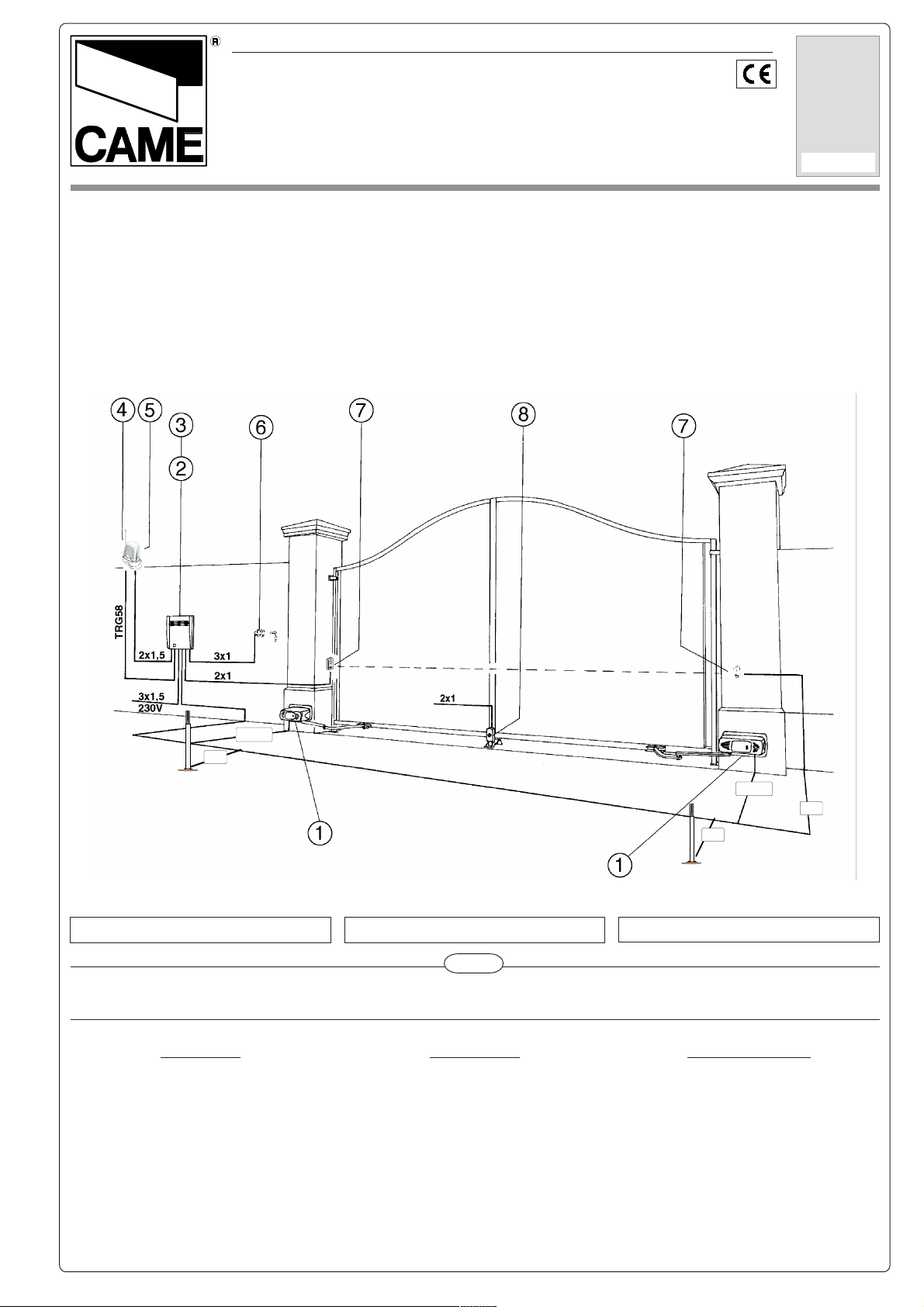
Impianto tipo
Standard installation
Instalación tipo
Cavi di alimentazione motori:
6 x 1.5 mm2 fino a 20 m
6 x 2.5 mm
2
fino a 30 m
DIR
DIR
4x1,5
4x1
2x1
DIR
ENGLISH ESPAÑOLITALIANO
F 1024
Power wires to motor:
6 x 1.5 mm2 up to 20 m
6 x 2.5 mm
2
up to 30 m
Cables de alimentación motores:
6 x 1.5 mm2 hasta 20 m
6 x 2.5 " " 30 m
Impianto tipo
1 - Motoriduttore
Accessori:
2 - Quadro comando
3 - Ricevitore radio
4 - Antenna
5 - Lampeggiatore di movimento
6 - Selettore a chiave
7 - Fotocellule di sicurezza
8 - Elettroserratura
Installation type
1 - Gear motor
Accessories:
2 - Control panel
3 - Radio receiver
4 - Antenna
5 - Flashing light indicating door movement
6 - Key-operated selector switch
7 - Safety photocells
8 - Electric lock
Instalación estándar
1 - Motorreductor
Accesorios
2 - Cuadro de mando
3 - Radiorreceptor
4 - Antena
5 - Lámpara intermitente de movimiento
6 - Selector con llave
7 - Fotocélulas de seguridad
8 - Electrocerradura
Page 2
I
Descrizione:
- Automazione esterna a braccio snodato per cancelli a battente.
- Progettato e costruito interamente dalla CAME S.p.A., risponde alle vigenti norme di sicurezza, con grado di protezione IP
54.
- Garantito 24 mesi salvo manomissioni.
Versioni:
F 1000
Motoriduttore irreversibile 230V a.c. - 150 W.
F 1100
Motoriduttore reversibile 230V a.c. - 110 W.
CARATTERISTICHE GENERALI
Accessori:
F1001
Braccio telescopico diritto (per singole ante da 0,5 a 2 m.).
H 3000
Dispositivo di sblocco a cordino (L= 5 m.) completo di contenitore di sicurezza, manopola di sblocco e pulsante.
LOCK 81
Elettroserratura di blocco a cilindro singolo.
LOCK 82
Elettroserratura di blocco a cilindro doppio.
F 1024
Motoriduttore irreversibile 24V d.c. - 180 W.
Limiti d'impiego:
- Dimensione ante fino a 4 metri (vedi tabella a pag. 5).
- Apertura dell’anta: max 90°.
- Per uso intensivo si consiglia l’utilizzo della versione F 1024.
GB
Description:
- External automation system with articulated arm for hinged gates.
- Designed and constructed entirely by CAME in compliance with
current safety standards, and with an IP54 protecting rating.
- Guaranteed for 24 months, unless tampered with by unauthorized
personnel.
Versions:
F 1000
230V a.c. - 150W irreversible gearmotor.
F 1100
230V a.c. - 110W reversible gearmotor.
F 1024
24V d.c. - 180W irreversible gearmotor.
Limits of use:
- Lenght of gate wings: up to 4 metres (see table on page 5).
- Max. angle of gate wing when open: 90°.
- For heavy-duty service, the E 1024 version should be used.
GENERAL SPECIFICATIONS
Attenzione! Controllate che le apparecchiature di comando,
di sicurezza e gli accessori siano originali CAME; ciò garantisce e rende l'impianto di facile esecuzione e manutenzione.
Accessories:
F1001
Straight telescopic arm (for single gate wings that are 0,5 to 2
m. long).
H 3000
Cable-operated (lenght 5 m.) manual release system, complete with safety housing, release knob and pushbutton.
LOCK 81
Single-cylinder electric lock.
LOCK 82
Double-cylinder electric lock.
Attention! to insure easy installation and conformance with
current safety norms, we raccomend installation of CAME
safety and control accessories.
E
Descripción:
- Automatización externa con brazo articulado para puertas con
bisagras.
- Diseñado y fabricado enteramente por CAME S.p.A., cumple
con las normas de seguridad vigentes, con grado de protección
IP54.
- Garantizado 24 meses, salvo manipulaciones.
Modelos:
F 1000
Motorreductor irreversible 230V a.c. - 150 W.
F 1100
Motorreductor reversible 230V a.c. - 110 W.
F 1024
Motorreductor irreversible 24V d.c. - 180 W.
Limites de empleo:
- Dimensión puertas de hasta 4 metros (ver la tabla en la pag. 5).
- Apertura de la puerta: max 90°.
CARACTERÍSTICAS GENERALES
Accessorios:
F1001
Brazio telescópico recto (para puertas individuales de 0,5 a 2
m.).
H 3000
Dispositivo de desbloqueo mediante cuerda (L= 5 m.) dotado
de contenedor de seguridad, pomo de desbloqueo y pulsador.
LOCK 81
Cerradura eléctica de bloqueo a cilindro individual.
LOCK 82
Cerradura eléctica de bloqueo a cilindro doble.
Atención! Atención!
Atención! Comprobar que los equipos de mando, de seguridad
Atención! Atención!
y los acesorios sean originales CAME; lo cual garantiza y
facilita el uso y el mantenimiento del aparato.
2
Page 3
ENGLISH ESPAÑOLITALIANO
DESCRIPCIÓN TÉCNICACARATTERISTICHE TECNICHE TECHNICAL FEATURES
OPIT
EPYT
OPIT
0001F
0011F
4201F
OSEP
THGIEW
OSEP
41.gK.c.aV032A3,1W051%03
31.gK.c.aV032A1W011%05
5,
.gK.c.dV4251A W081
41
- Dati relativi ai valori di alimentazione nominale - * Regolabile mediante quadri comando CAME.
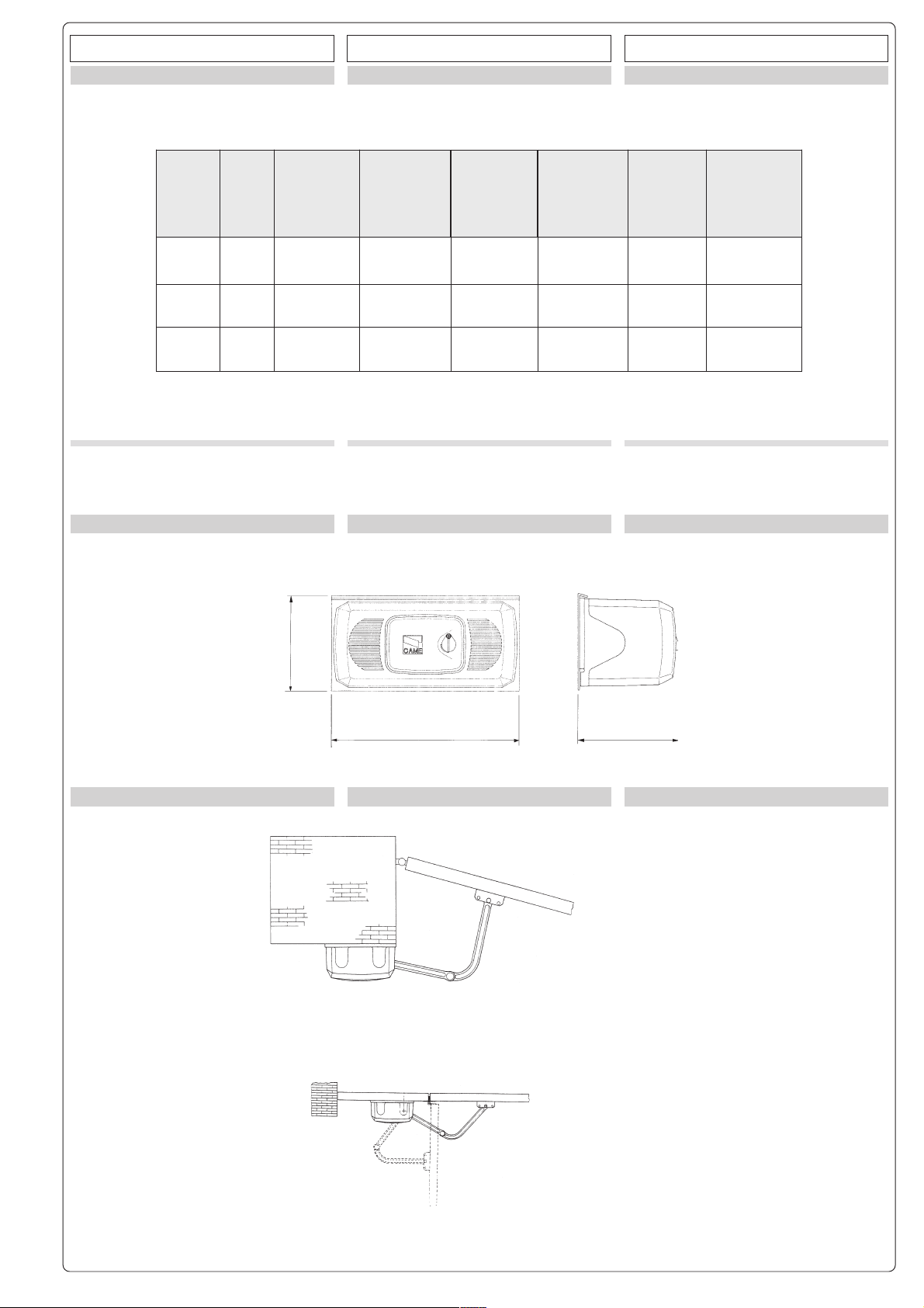
MISURE DI INGOMBRO DIMENSIONES MÁXIMAS
ETNERROC
ENOIZATNEMILA
YLPPUSREWOP
NÓICATNEMILA
ELANIMON
LANIMON
TNERRUC
ETNEIRROC
LANIMON
AZNETOP
EROTOM
REWOPROTOM
AICNETOP
ROTOM
- Data refers to nominal power supply - * Can
be adjusted using CAME control panels.
EXTERNAL DIMENSIONS
.TIMRETNI
OROVAL
ELCYCYTUD
.MRETNI
OJABART
ovisnetnioizivreS
elcycytudyvaeH
ovisnetnioicivreS
AIPPOC
EUQROT
AJERAP
ROTOM
* m.N023
* m.N083
* m.N074
EROTASNEDNOC
ROTICAPAC
RODASNEDNOC
Fµ01
Fµ3,6
/
- Datos relativos a los valores de la tensión
nominal. - * Ajustable mediante los cuadros
de mando CAME.
168
340
178
ESEMPI DI APPLICAZIONE EXEMPLES OF APPLICATIONS EJEMPLOS DE APLICACIONES
Al pilastro
To the pillar
Al pilar
Ad anta fissa
With fixed shutter
A puerta fija
3
Page 4
ENGLISH ESPAÑOLITALIANO
LIMITI D’IMPIEGO
*Qualora l’anta superi i 2,5 m. é necessaria
l’applicazione di un’elettroserratura per
F1000 e F 1024, mentre é sempre necessaria per F 1100.
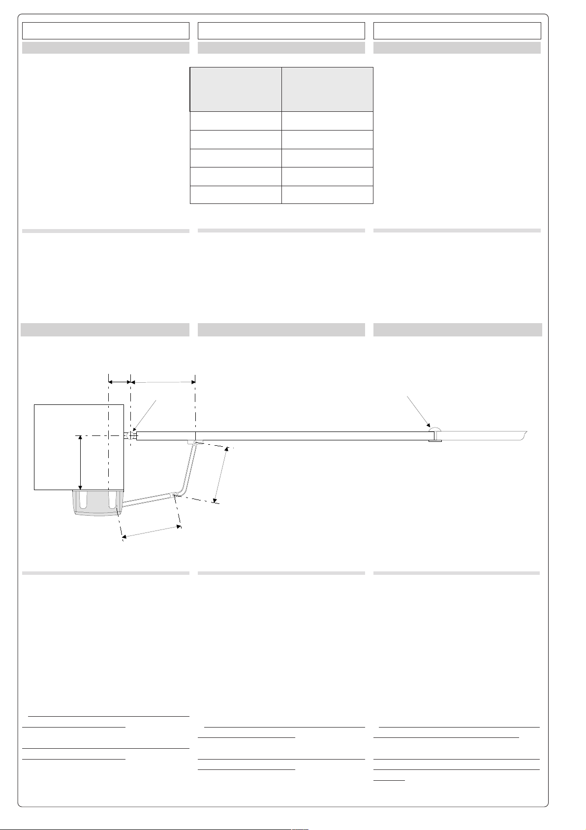
PRIMA DELL’INSTALLAZIONE... ANTES DE INSTALAR EL AUTOMATISMO...BEFORE INSTALLING...
atnaazzehgraL
gniwetagfohtdiW
ajohohcnA
atnaoseP
ajohoseP
00.2008
*
05.2
006
00.3005
05.3054
00.4004
*Whenever the shutter is over 2,5 m., it
needs an electrical lock (F1000 - F1024); F
1100 always needs it.
LIMITES DE EMPLEOOPERATING LIMITS
gniwetagfothgieW
*En el caso de que la puerta supere los 2,5
m. es necesaria la saldadura electrica
(F1000-F1024), mientras que es siempre
necesaria para F1000.
PilastroPilastro
Pilastro
PilastroPilastro
Pillar
PilarPilar
Pilar
PilarPilar
*A
B
*
450450
450
450450
CernieraCerniera
Cerniera
CernieraCerniera
Hinge
BisagraBisagra
Bisagra
BisagraBisagra
350350
350
350350
Prima di procedere all’installazione dell’automatismo, controllare che:
- la struttura del cancello sia adeguatamente robusta, le cerniere siano efficienti e che
non vi sia attrito tra parti fisse e mobili;
- il percorso dei cavi elettrici sia eseguito
secondo le disposizioni di comando e sicurezza (vedi impianto tipo).
- ci sia una battuta d’arresto meccanico in
chiusura (ben fissata al suolo) per evitare
l’oltrecorsa anta/motoriduttore.
*
Se B e’ compreso tra 0 e 300 mm, A deve
misurare almeno 110 mm.
Se B e’ compreso tra 300 e 380 mm, A deve
misurare almeno 150 mm.
Battuta d’arrestoBattuta d’arresto
Battuta d’arresto
Battuta d’arrestoBattuta d’arresto
Mechanical stop
Tope de paradaTope de parada
Tope de parada
Tope de paradaTope de parada
400400
400400
400
Before beginning installation of the automation system, check the following:
- the movement of the door must be smooth
from the fully-open to the fully-closed positions, with no friction or play between the
bearings (1) and the pulleys (2);
- the door itself must be sufficently solid and
the hinges (3) must be efficent (articulated
overhead door);
- the electrical wiring path according to the
position of the control and safety instruments (see installation type).
*
If distance B is 0 to 300 mm, distance A
must be at least 110 mm
If distance B is 300 to 380 mm, distance A
must be at least 150 mm
Antes de proceder a la instalación del automatismo, controlar:
- el movimiento de la puerta sea uniforme a
lo largo de toda la cerrera, evitando roces o
juegos entre los cojintes de deslizamiento
(1) y las poleas (2);
- la estructura de la puerta basculante sea
suficientemente fuerte y las adecuadas
(basculante articulada);
- el recorrido de los cables eléctricos según
las disposiciones de mando y seguridad
(véase Instalación estándar).
*
Si B está comprendido entre 0 y 300 mm.,
A debe medir 110 mm como minimo.
Sin enbargo si B está comprendido entre
300 y 380 mm, A debe medir 150 mm como
minimo.
4
Page 5

ENGLISH ESPAÑOLITALIANO
APPLICAZIONE DELLA PIASTRA-BASE E DELLA STAFFA “A”
Piastra base
Base plate
Placa base
APPLICATION OF THE BASIS-PLATE AND OF THE STIRRUP
ø 14
APPLICACION PLACA BASE Y ESTRIBO “A”
Staffa “A”
Bracket “A”
Estribo “A”
ø 8
Vista frontale
Front view
Vista frontal
150 min.
ø 8
450
19
- Fissare la piastra-base al pilastro con viti
ø8 e tasselli ø14 rispettando la quota minima di 150 mm. dalla pavimentazione.
- Fissare la staffa “A” (con viti ø8 o saldatura)
all’anta del cancello rispettando le quote di
450 e 19 mm.
- Use ø8 screws and ø14 screw anchors to
mount the base plate on the pillar. Be sure
to respect the 150 mm. minimum distance
from the pavement.
- Attach bracket “A” to the gate wing (use ø8
screws or wlds). Be sure to respect the
offsets of 450 mm. and 19 mm. between the
pillar-base plate assembly and bracket “A”.
5
- Fijar la placa base al pilar con tornillos ø8
y tacos ø14 respetando la cota mínima de
150 mm. del suelo.
- Fijar el estribo “A” (con tornillos ø8 o
saldadura) en la puerta respetando las cotas de 450 y 19 mm. correspondientes a la
desalineado entre placa-base y estribo “A”.
Page 6

ENGLISH ESPAÑOLITALIANO
M 8 x 110
INSTALLATIONINSTALLAZIONE
INSTALACIÓN
- Inserire il motore nella piastra-base e fissarlo con le due viti M8x110 e relativi dadi in
dotazione.
M 8
Fig. 1
- Insert the motor into the plate-base and
secure it with the two screws M8x110 and
related nuts (supplied).
- Monte el motor en la placa de base y
fíjelo con los dos tornillos M8x110 y las
tuercas entregadas.
6
Page 7

ENGLISH ESPAÑOLITALIANO
APPLICAZIONE DEI BRACCI DIRITTO E CURVO
APPLICATION STRAIGHT AND CURVED ARMS APPLICACIÓN BRAZOS DERECHO Y CURVADO
M6 x 20M6 x 20
M6 x 20
M6 x 20M6 x 20
Rondella svasataRondella svasata
Rondella svasata
Rondella svasataRondella svasata
Countersunk washer
Arandela biseladaArandela biselada
Arandela biselada
Arandela biseladaArandela biselada
ManopolaManopola
Manopola
ManopolaManopola
Knob
ManillaManilla
Manilla
ManillaManilla
M12 x 50M12 x 50
M12 x 50
M12 x 50M12 x 50
M12M12
M12
M12M12
- Inserire il semibraccio diritto nell’albero
quadro del motore. Applicare la rondella
svasata, la vite M6x20 e bloccare il
semibraccio con i due grani. Unire e fissare
i due bracci con la rondella e la vite M8x16.
Sbloccare il motore (vedi pag. 13) e
fissare il semibraccio curvo alla staffa “A”
con la vite M12x50 e il dado M12 verificandone il libero scorrimento. Per applicazione
destra vedere fig. 2.
M8 x 16M8 x 16
M8 x 16
M8 x 16M8 x 16
Fig. 2
- Insert the straight semi-arm, without letting
it outside the drive shaft. Apply the flared
washer, the M6x20 screw and block the
semi-arm trought the two grains. Join and
fix the two arms with the washer and the
M8x16 screw. Release the motor (rotating
the hand grip in the direction of the arrow)
and fix the curved arm to the “A” stirrupthrought
the M12x50 screw and the M12 nut. For rightsided application, see picture 2.
- Introducir el semibrazo recto no dejándolo
sobresalir del árbol cuadrado del motor.
Aplicar la arandela avellanada, el tornillo
M6x20 y bloquer el semibrazo recto con
dos tornillos prisioneros. Unir y fijar los dos
brazos con la arandela y el tornillo M8x16.
Desbloquear el motor (girando la manilla en
el sentido de la flecha) y fijar el brazo curvado al estribo “A” con el tornillo M12x50 y la
tuerca M12. Para la aplicacion derecha
ver fig. 2.
7
Page 8

ENGLISH ESPAÑOLITALIANO
QUADRI COMANDO : COLLEGAMENTI ELETTRICI CONTROL PANELS: ELECTRICAL CONNECTIONS CUADROS DE MANDO : CONEXIONES ELÉCTRICAS.
Morsettiera quadro comando
Control panel terminal block
Caja de bornes cuadro de mando
U -V -WU -V -W
U -V -WU -V -W
U -V -W
1: 1:
1: 1:
1:
MotoreMotore
MotoreMotore
Motor
Motore
ZA5 - ZA4
ZA3 - ZF1
ZM2
Quadri
Panels
Cuadros
X -Y -W X -Y -W
X -Y -W X -Y -W
X -Y -W
2: 2:
2: 2:
2:
MotoreMotore
MotoreMotore
Motore
Motor
ZF1- ZA4
ZA3 - ZM2
Quadri
Panels
Cuadros
Morsettiera motore
Motor terminal block
Caja de bornes para el motor
U V WU V W
U V WU V W
U V W
Massa -
Ground
- Tierra
F 1000 - F 1100
U -V -W
Collegamento motore 1
Connection to motor 1
Conexión motor 1
X -Y -W
Collegamento motore 2
Connection to motor 2
Conexión motor 2
- Installare il quadro comando e procedere ai collegamenti elettrici come indicato.
- Install the electrical control panel and connect the wiring as indicated.
- Installar el cuadro de mando y proceder a las conexiones eléctricos según lo indicado.
QQ
UADROUADRO
Q
UADRO
UADROUADRO
QQ
F 1024
COMANDOCOMANDO
COMANDO
COMANDOCOMANDO
ZL 19: ZL 19:
ZL 19:
ZL 19: ZL 19:
COLLEGAMENTICOLLEGAMENTI
COLLEGAMENTI
COLLEGAMENTICOLLEGAMENTI
ELETTRICIELETTRICI
ELETTRICI
ELETTRICIELETTRICI
ZL 19 ZL 19
ZL 19
ZL 19 ZL 19
CONTROLCONTROL
CONTROL
CONTROLCONTROL
PANELPANEL
PANEL
PANELPANEL
: :
:
: :
Morsettiera quadro comando
Control panel terminal block
ELECTRICALELECTRICAL
ELECTRICAL
ELECTRICALELECTRICAL
CONNECTIONSCONNECTIONS
CONNECTIONS
CONNECTIONSCONNECTIONS
CC
C
CC
UADROUADRO
UADRO
UADROUADRO
Caja de bornes cuadro de mando
M -N
Collegamento motore
Connection to motor
Conexión motor
F -Fa
Microinterruttore di finecorsa in apertura
Microswitch-limit switch on aperture
Microinterruptor final de recorrido en la apertura
C-Rc1-Fa1-C-M1-N1C-Rc1-Fa1-C-M1-N1
C-Rc1-Fa1-C-M1-N1C-Rc1-Fa1-C-M1-N1
C-Rc1-Fa1-C-M1-N1
C-Rc2-Fa2-C-M2-N2 C-Rc2-Fa2-C-M2-N2
C-Rc2-Fa2-C-M2-N2 C-Rc2-Fa2-C-M2-N2
C-Rc2-Fa2-C-M2-N2
1: 1:
1: 1:
2: 2:
2: 2:
1:
2:
R -Rc
MotoreMotore
MotoreMotore
MotorMotor
MotorMotor
Motore
Motor
MotoreMotore
MotoreMotore
MotorMotor
MotorMotor
Motore
ZL19 ZL19
ZL19
ZL19 ZL19
Motor
Microinterruttore di rallentamento in chiusura
Microswitch-deceleration on closure
Microinterruptor de deceleraciön en el cierre
- per ZL170 vedere relativa documentazione
- for ZL170, see related documentation
- para ZL170 véase la documentación respectiva
MANDOMANDO
MANDO
MANDOMANDO
ZL 19: ZL 19:
ZL 19:
ZL 19: ZL 19:
CONEXIONESCONEXIONES
CONEXIONES
CONEXIONESCONEXIONES
DEDE
DE
DEDE
Morsettiera motore
Motor terminal block
Caja de bornes para el motor
N M F Fa Rc RN M F Fa Rc R
N M F Fa Rc RN M F Fa Rc R
N M F Fa Rc R
ELÉCTRICASELÉCTRICAS
ELÉCTRICAS
ELÉCTRICASELÉCTRICAS
- Installare il quadro comando e procedere ai collegamenti elettrici come indicato.
- Install the electrical control panel and connect the wiring as indicated.
- Installar el cuadro de mando y proceder a las conexiones eléctricos según lo indicado.
8
Page 9

ENGLISH ESPAÑOLITALIANO
REGOLAZIONE MICROINTERRUTTORI DI STOP IN APER-
TURA E CHIUSURA
In apertura: sbloccare e portare l’anta nella
posizione di apertura desiderata. Ruotare la
camma superiore fino a far inserire il
microinterruttore e avvitare la vite posta
nella relativa camma.
ADJUSTMENT OF STOP MICROSWITCHES DURING
AND CLOSING
OPENING
During opening: release and move the door
to the open position desired. Turn the upper
cam until the microswitch is activated and
screw the screw in the related cam.
F 1000 - F 1100
Camma inferiore
Lower cam
Leva inferior
REGULACIÓN MICROINTERRUPTORES DE PARADA
DURANTE
APPERTURAY CIERRE
En apertura: desbloquee y coloque la hoja
en la posición de apertura deseada. Gire la
leva superior hasta hacer entrar el
microinterruptor y enrosque el tornillo
situado en la leva correspondiente.
Camma superiore
Upper cam
Leva superior
Microinterrutore
Microswitches
Microinterruptores
In chiusura (solo F 1000): sbloccare e portare l’anta nella posizione di chiusura desiderata. Ruotare la camma inferiore fino a far
inserire il microinterruttore e avvitare la vite
posta nella relativa camma.
REGOLAZIONE MICROINTERRUTTORI DI STOP IN APERTU-
RA E RALLENTAMENTO IN CHIUSURA
In apertura: sbloccare e portare l’anta nella
posizione di apertura desiderata. Ruotare la
camma superiore fino a far inserire il
microinterruttore e avvitare la vite posta
nella relativa camma.
In chiusura: sbloccare e portare l’anta a
circa 100 mm. dalla battuta d’arresto in
chiusura. Ruotare la camma inferiore fino a
far inserire il microinterruttore e avvitare la
vite posta nella relativa camma.
During closure (F1000 only): release the
door and move it to the desired closing
position. Turn the lower cam until the
microswitch is activated and screw the
screw in the related cam.
ADJUSTING OF MICROSWITCHES THAT STOP THE MOTOR
THE END OF THE OPENING CYCLE AND ACTIVATE
AT
SLOWDOWN
BEFORE CLOSURE
During opening: release and move the door
to the open position desired. Turn the upper
cam until the microswitch is activated and
screw the screw in the related cam.
During closure: release and move the door
to approximately 100 mm. from the closure
end stop. Turn the lower cam until the
microswitch is activated and screw the screw
in the related cam.
F 1024
Camma inferiore
Lower cam
Leva inferior
En cierre (sólo F1000): desbloquee y
coloque la hoja en la posición de cierre
deseada. Gire la leva inferior hasta hacer
entrar el microinterruptor y enrosque el
tornillo situado en la leva correspondiente.
REGULACIÓN MICROINTERRUPTORES DE PARADA EN APER-
TURA Y RALENTAMIENTO EN CIERRE
En apertura: desbloquee y coloque la hoja
en la posición de apertura deseada. Gire la
leva superior hasta hacer entrar el
microinterruptor y enrosque el tornillo situado
en la leva correspondiente.
En cierre: desbloquee y coloque la hoja a
alrededor de 100 mm del tope de parada en
cierre. Gire la leva inferior hasta hacer entrar
el microinterruptor y enrosque el tornillo
situado en la leva correspondiente.
Camma superiore
Upper cam
Leva superior
Microinterrutore
Microswitches
Microinterruptores
9
Page 10

ENGLISH ESPAÑOLITALIANO
Dopo aver ultimato le operazioni di montaggio, collegamenti elettrici e regolazioni, procedere a ribloccare il motore ed inserire il
coperchio fissandolo mediante le quattro
viti in dotazione.
After assembling the unit, connecting up the
wiring and performing adjustments, proceed
to jam the motor again and insert the cover
fitting it using the four screws supplied with
the unit.
Una vez terminadas las operaciones de
montaje, las conexiones eléctricas y los
ajustes, volver a bloquear el motor y
introducir la tapa fijándola mediante los
cuatro tornillos suministrados.
- da effettuare a motore fermo
- to be done while motor is off
- debe efectuarse con motor parado
ø 3,9x13
DESBLOQUEO DE EMERGENCIASBLOCCO DI EMERGENZA EMERGENCY RELEASE
F 1000 - F 1024
Manopola
Knob
Manecilla
Sblocco
Release
Desbloqueo
Blocco
Block
Bloqueo
In caso di assenza di corrente o guasti,
sbloccare il motoriduttore agendo sull’apposita manopola.
In case of power failure or malfunction,
unlock the gear motor by using the knob
provided.
10
En caso de falta de corriente o averÌa,
desbloquear el motorreductor actuando en
la correspondiente manilla.
Page 11

ENGLISH ESPAÑOLITALIANO
ACCESSORI OPZIONALI ACCESORIOS OPCIONALESOPTIONAL ACCESSORIES
Dispositivo di sblocco a cordino (L = 5 m.)
completo di contenitore di sicurezza, manopola di sblocco e pulsante.
NOTA: evitare di formare con il cordino di
sblocco angoli acuti (1) o retti (2).
H3000
Contenitore di sicurezza
Protective casing
Contenedor de seguridad
Disposal of connecting-release (L = 5 m.)
complete of surety-container, release hand
grip and push-button.
NOTE: avoid to create any acute or right
angle with the release-connector.
Uscita cordino
Cord exit
Salida cuerd
Dispositivo de desbloqueo a cuerda (L= 5
m.), con caja de seguridad, manilla de
desbloqueo y botón.
NOTA: evitar formar angulos rectos o agudos
con la cuerda.
aa
a
aa
Braccio telescopico diritto (per ante singole da 0,5 a 2 m. - F3000 - F3024: 1,5 m.
max).
F1001
Elettroserrature di blocco (alimentazione
12V).
LOCK81- LOCK82
MANUTENZIONI PERIODICHE
Il gruppo non necessita di alcuna manutenzione specifica. Solo come misura
cautelativa e in caso di servizio intensivo e’
opportuno controllare l’integrita’ del cavo
elettrico collegato al motore e ingrassare i
punti di scorrimento tra parti fisse e mobili.
Straight telescopic arm (for single gate
wings that are 0,5 to 2 m. long - Models
F3000 - F3024: max. lenght is 1,5 m.).
BraccioBraccio
Braccio
BraccioBraccio
Arm
BrazoBrazo
Brazo
BrazoBrazo
Electric locks (12V power supply). Electrocerraduras de bloqueo (alimenta-
PERIODIC MAINTENANCE
This grouoe requires no specific maintenance. However, as a precaution and in
case of heavy-duty service, it is advisable
to ceck the cable connected to the motor
and to grease the bushings, the arm and the
bearing guides at regular intervals.
Brazo telescópico recto (para puertas individuales de 0,5 a 2 m. - F3000-F3024: 1,5
m. máx).
TuboTubo
Tubo
TuboTubo
Tube
TuboTubo
Tubo
TuboTubo
ción 12V).
MANTENIMIENTO PERIÓDICO
El conjunto no necesita ningún mantenimiento especifico. Sólo como medida
cautelar y en caso de uso intensivo es
conveniente controlar el cable conectado
al motor y engrasar los casquillos, los brazos y las guías de los cojinetes de deslizamiento.
11
Page 12

DICHIARAZIONE DEL FABBRICANTE
Allegata alla documentazione tecnica (l’originale della Dichiarazione è disponibile a richiesta)
I Rappresentanti della
CAME Cancelli Automatici S.p.A.
via Martiri della Libertà, 15
31030Dosson di Casier - Treviso - ITALYtel
(+39) 0422 4940 - fax (+39) 0422 4941
internet: www.came.it - e-mail: info@came.it
Dichiarano sotto la propria responsabilità che i/il prodotto/i denominato/i ...
F1000 • F1100 • F1024
F1001 • H3000 • LOCK81 • LOCK82
… sono conformi alle disposizioni legislative Nazionali che traspongono le seguenti
Direttive Comunitarie (dove specificatamente applicabili):
DIRETTIVA MACCHINE 98/37/CE
D
IRETTIVA BASSA TENSIONE 73/23/CEE - 93/68/CEE
D
IRETTIVA COMPATIBILITÀ ELETTROMAGNETICA 89/336/CEE - 92/31/CEE
IRETTIVA R&TTE 1999/5/CE
D
Ai sensi dell’Allegato II B della Direttiva Macchine 98/37/CE
Documentazioni tecniche specifiche dei prodotti sono disponibili a richiesta!
MANUFACTURER’S DECLARATION
Enclosed with the technical documentation (the original copy of the Declaration is available on request)
The representatives of
CAME Cancelli Automatici S.p.A.
via Martiri della Libertà, 15
31030 Dosson di Casier - Treviso - ITALY
tel (+39) 0422 4940 - fax (+39) 0422 4941
internet: www.came.it - e-mail: info@came.it
Hereby declare, under their own respons ibility, that the product/s called ...
F1000 • F1100 • F1024
F1001 • H3000 • LOCK81 • LOCK82
… comply with the Italian National Legal Provisions that transpose the
following Community Directives (where specifically applicable):
MACHINERY DIRECTIVE 98/37/CE
L
OW VOLTAGE DIRECTIVE 73/23/EEC - 93/68/EEC
ECTROMAGNETIC COMPATIBILITY DIRECTIVE 89/336/EEC - 92/31/EEC
L
IRECTIVE 1999/5/CE
R&TTE D
As per Enclosure II B of Machinery Directive 98/37/CE
Specific technical documentation on the products is available on request!
Inoltre, dichiara che il/i prodotto/i, oggetto della presente dichiarazione, sono costruiti nel
rispetto delle seguenti principali norme armonizzate:
EN 292 PAR TE 1ª E 2ª SICUREZZA DEL MACCHINARIO.
EN 12453 C
EN 12445 C
EN 60335 - 1 S
EN 60204 - 1 S
EN 50081 - 1
EN 50082 - 1
AVVERTENZA IMPORTANTE!
È vietato mettere in servizio il/i prodotto/i, oggetto della presente dichiarazione, prima del
completamento e/o incorporamento, in totale conformità alle disposizioni della Direttiva
Macchine 98/37/CE
E 2COMPATIBILITÀ ELETTROMAGNETICA.
E 2COMPATIBILITÀ ELETTROMAGNETICA.
Data della presente dichiarazione 07/12/2001
HIUSURE INDUSTRIALI, COMMERCIALI …
HIUSURE INDUSTRIALI, COMMERCIALI …
ICUREZZA NEGLI APPARECCHI AD USO DOMESTICO ...
ICUREZZA DEL MACCHINARIO.
Firma dei Rappresentanti
RESPONSABILE TECNICO
Sig. Gianni Michielan
PRESIDENTE
Sig. Paolo Menuzzo
Date of the present declaration 07/12/2001
Also, they furthermore represent and warrant that the product/s that are the subject of the
present Declaration are manufactured in the respect of the following main harmonized
provisions:
EN 292 PAR T 1 AND 2MACHINERY SAFETY.
EN 12453 I
EN 12445 I
EN 60335 - 1 S
EN 60204 - 1 M
EN 50081 - 1
EN 50082 - 1
IMPORTANT CAUTION!
It is forbidden to market/use product/s that are the subject of this declaration before
completing and/or incorporating them in total compliance with the provisions of Machinery
Directive 98/37/CE
AND 2ELECTROMAGNETIC COMPATIBILITY.
AND 2ELECTROMAGNETIC COMPATIBILITY.
NDUSTRIAL, COMMERCIAL AND OTHER CLOSING MECHANISMS.
NDUSTRIAL, COMMERCIAL AND OTHER CLOSING MECHANISMS.
AFETY IN APPARATUSES FOR HOME USE.
ACHINERY SAFETY.
Signatures of the Representatives
TECHNICAL MANAGER
Mr. Gianni Michielan
MANAGING DIRECTOR
Mr. Paolo Menuzzo
DECLARACION DEL FABRICANTE
De conformidad con el Anexo II B de la Directiva de Máquinas 98/37/CE
petición)
Los Representantes de la compañía
CAME Cancelli Automatici S.p.A.
via Martiri della Libertà, 15
31030 Dosson di Casier - Treviso - ITALY
tel (+39) 0422 4940 - fax (+39) 0422 4941
internet: www.came.it - e-mail: info@came.it
Declaran bajo su responsabilidad que el/los producto/s denominado/s ...
F1000 • F1100 • F1024
F1001 • H3000 • LOCK81 • LOCK82
… cumplen con las disposiciones legislativas nacionales que trasponen las siguientes
Directivas Comunitarias (donde específicamente aplicables):
DIRECTIVA DE MÁQUINAS 98/37/CE
D
IRECTIVA DE BAJA TENSIÓN 73/23/CEE - 93/68/CEE
D
IRECTIVA DE COMPATIBILIDAD ELECTROMAGNÉTICA 89/336/CEE - 92/31/CEE
D
IRECTIVA R&TTE 1999/5/CE
Documentación técnica específica de los productos está disponible previa petición
Tutti i dati sono stati controllati con la massima cura. Non ci
assumiamo comunque alcuna responsabilità per eventuali errori od
omissioni.
ASSISTENZA TECNICA
NUMERO VERDE
SISTEMA QUALITÀ
CERTIFICATO
800 295830
EB
W
www.came.it
E-
MAIL
CANCELLI AUTOMATICI
info@came.it
CAME CANCELLI AUTOMATICI S.P.A.
DOSSON DI CASIER (TREVISO)
(+39) 0422 4940 (+39) 0422 490944
All data checked with the maximum care. However, no liability is accepted
for any error or omission.
CAME LOMBARDIA S.R.L.______COLOGNO M. (MI)
(+39) 02 26708293 (+39) 02 25490288
CAME SUD S.R.L. ___________________NAPOLI
(+39) 081 7524455 (+39) 081 7529109
CAME (AMERICA) L.L.C.____________MIAMI ( FL)
(+1) 305 5938798 (+1) 305 5939823
CAME AUTOMATISMOS S.A__________MADRID
(+34) 091 5285009 (+34) 091 4685442
CAME BELGIUM__________________LESSINES
(+32) 068 333014 (+32) 068 338019
Fecha de la presente declaración 07/12/2001Adjunta a la documentación técnica (el original de la Declaración está disponible previa
Los productos objeto de esta declaración están fabricados respetando las siguientes normas
armonizadas:
EN 292 PAR T E 1ª Y 2ª SEGURIDAD DE LAS MÁQUINAS.
EN 12453 C
EN 12445 C
EN 60335 - 1 SEGURIDAD DE LOS APARATOS PARA USO DOMÉSTICO...
EN 60204 - 1 S
EN 50081 - 1
EN 50082 - 1 E 2COMPATIBILIDAD ELECTROMAGNÉTICA.
AVVERTENZA IMPORTANTE!
Está prohibido hacer uso de el/los producto/s, objeto de la presente declaración antes de
completarlo/s y/o incorporarlo/s en total conformidad a las disposiciones de la Directiva de
Máquinas 98/37/CE.
E 2COMPATIBILIDAD ELECTROMAGNÉTICA.
IERRES INDUSTRIALES, COMERCIALES …
IERRES INDUSTRIALES, COMERCIALES …
EGURIDAD DE LAS MÁQUINAS.
Firma de los Representantes
RESPONSABLE TÉCNICO
Sr. Gianni Michielan
Todos los datos se han controlado con la máxima atención. No
obstante no nos responsabilizamos de los posibles errores u omisiones.
PRESIDENTE
Sr. Paolo Menuzzo
CAME FRANCE S.A.____NANTERRE CEDEX (PARIS)
(+33) 01 46130505 (+33) 01 46130500
CAME GMBH________KORNTAL BEI (STUTTGART)
(+49) 07 15037830 (+49) 07 150378383
CAME GMBH____________SEEFELD BEI (BERLIN)
(+49) 03 33988390 (+49) 03 339885508
CAME PL SP.ZO.O______________WARSZAWA
(+48) 022 8365076 (+48) 022 8369920
CAME UNITED KINGDOM LTD___NOTTINGHAM
(+44) 0115 9210430 (+44) 0115 9210431
 Loading...