

Page 1
CANCELLI AUTOMATICI
SERIE R |
COSTOLA DI SICUREZZA A RAGGI INFRAROSSI
INFRARED-CONTROLLED SAFETY RIBBING
DISPOSITIF DE SÉCURITÉ À RAYONS INFRAROUGED
I
NFRAROT-SICHERHEITSLEISTE
PROTECTOR DE SEGURIDAD A INFRARROJOS
I
NFRAROOD FOTOCEL VOOR VEILIGHEIDSPROFIEL
R
SERIES
|
SÉRIE R |
BAUREIHE
R |
SERIE R /
SERIE
R
DOC MS
Documentazione
Tecnica
M25
rev. 3.0
07/2002
©
CAME
CANCELLI
AUTOMATICI
119RM25
I
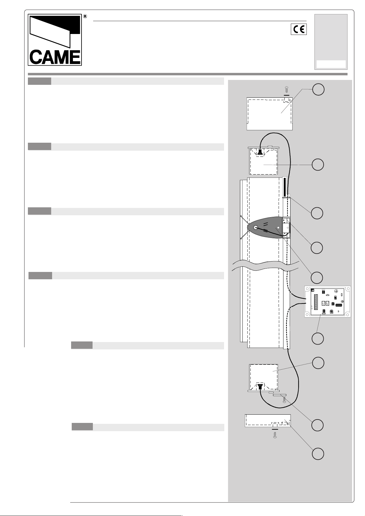
DESCRIZIONE
1) Tappo esterno di chiusura superiore in gomma sintetica (fissaggio con una
vite ø 3.9 x 9.5 UNI6594 e rondella ø 4 alla staffa di fissaggio);
2) Tappo porta-ottica in gomma sintetica (inserimento a contrasto);
3) Staffa di fissaggio tappo esterno superiore;
4) Profilo in alluminio lega UNI 6060;
5) Costola in gomma EPL 60 shore;
6) Contenitore in PVC dei circuiti elettronici e dei collegamenti;
7) Piastrina ferma-tappo (fissaggio con 2 viti ø 2,9 x 9,5 UNI 6594 al profilo di alluminio);
8) Tappo esterno di chiusura inferiore con fori di scarico.
GB
DESCRIPTION
1) External upper closing stopper in synthetic rubber (mounted with a 3.9 mm ø x 9.5
mm UNI6594 screw and a 4 mm ø washer on the mounting bracket);
2) Trasmitting sintethic rubber stopper containing optics (pressure coupling);
3) External upper stopper mounting bracket;
4) Profile in UNI 6060 aluminium alloy;
5) Rubber rib in 60 shore EPL;
6) PVC casing containing the electrical circuits and connections;
7) Stopper fixing plate (fixing by 1 screw ø 3.9 x 9.5 UNI 6594 and ø 4 washer to the
arrest plate);
8) External lower stopper with outlet holes.
F
DESCRIPTION
1) Bouchon externe de fermeture supérieur en caoutchouc synthétique (à fixer
avec une vis ø 3,9 x 9,5 UNI6594 et une rondelle ø4 à la bride de fixation);
2) Bouchon porte- optique en caoutchouc synthétique (introduction en butée);
3) Bride de fixation du bouchon externe supérieur;
4) Profilé en aluminium alliage UNI 6060;
5) Profilé en caoutchouc EPL
6) Boîtier en PVC pour les circuits électroniques et les branchements;
7) Plaque pour bloquer le bouchon (à fixer au profilé en aluminium avec deux vis
ø 2.9 x 9.5 UNI 6594);
8) Bouchon externe de fermeture inférieur avec trous pour évacuer l’eau.
1
Parte alta
Top part
Partie haute
Oberteil
Parte superior
Bovenzijde
2
3
4
D
1) Externer oberer Verschlußdeckel aus synthetischem Gummi (Befestigung am
Halterungsbügel mit einer Schraube ø 3,9 x 9,5 UNI6594 und einer Unterlegscheibe
BESCHREIBUNG
ø4);
2) Optoelektronischer Deckel aus synthetischem Gummi (gegenüberliegeng
einsetzen);
3) Halterungsbügel oberer externer Deckel;
4) Profil aus Aluminium-legierung UNI 6060;
5) Gummileiste EPL 60 shore;
6) PVC-Gehäuse für elektronische Schaltkreise und Anschlüsse;
7) unterer externer Verschlußdeckel mit Abflußlöchern;
8) Blockierungsplättchen für Deckel.
E
DESCRIPCION
1) Tapa exterior de cierre superior de caucho sintético
(sujeción con un tornillo Ø 3,9 x 9,5 UNI6594 y arandela Ø 4 al
estribo de sujeción);
2) Tapón porta-óptica de goma sintética (introducción a
contraste);
3) Estribo de sujeción de la tapa exterior superior;
4) Perfil de aluminio aleación UNI 6060;
5) Protección de goma EPL;
6) Caja en PVC que contiene los circuitos electrónicos y las
conexiones;
7) Placa de sujeción de la tapa (anclaje con 2 tornillos ø 2,9 x
9,5 UNI 6594 al perfil de aluminio);
8) Tapa exterior de cierre inferior con agujeros de descarga.
NL
OMSCHRIJVING
1) Externe dichting boven vervaardigd uit synthetisch rubber (te
bevestigen met een schroef ø 3,9 x 9,5 UNI6594 en een rondel ø4
op de bevestigingsbeugel);
2) Houder zender in synthetisch rubber, wordt door een druk
bevestigd ;
3) Bevestiging voor bovenste dichting;
4) Aluminiumprofiel UNI 6060;
5) Rubberprofiel in EPL
6) PVC behuizing voor elektrische aansluiting;
7) Blokkering voor dichting (te bevestigen op het aluminium profiel
met 2 schroeven ø 2.9 x 9.5 UNI 6594);
8) Buitendichting voor onderaan met waterafvoer.
Parte bassa
Bottom part
Partie basse
Unterteil
Parte inferior
Onderzijde
5
DOC ME
24V12V
TX
M
B
1 C
A
242
+
C
C
4
V
/
/
D
121
_
C
2
V
NC RX
1
+ sens -
6
2
7
8
Page 2
CARATTERISTICHE TECNICHE
I
Alimentazione: 12/24V a.c./d.c.
Assorbimento: 80 mA
Portata contatti relè: 1A max. a 24V;
Grado di protezione: IP 54
Portata: il dispositivo è applicabile su costole
fino a 8 m di lunghezza
Sensibilità: regolabile mediante trimmer
GB
TECHNICAL CHARACTERISTICS
Power supply: 12/24V a.c./d.c.
Absorption: 80 mA
Relay capacity: 1A max at 24V;
Protection rating: IP 54
Operation field: For max 8 m long ribs
Sensitivity: adjustable by trimmer
CARACTERISTIQUES TÉCHNIQUES
F
Alimentation: 12/24V a.c./d.c.
Absorbtion: 80 mA
Portée contacts relais: 1A max. a 24V;
Degré de protection: IP 54
Champ d'utilisation: dispositif applicable à
des profilés allant jusqu'à 8 m. de long
Sensibilité: réglable à l'aide d'un trimmer
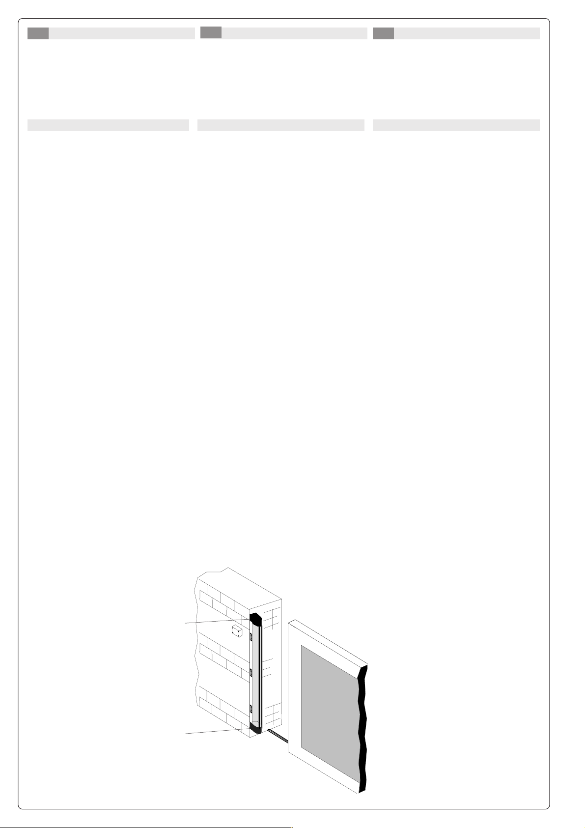
MONTAGGIO
1) Predisporre i fori per il passaggio
cavi nel profilo di alluminio;
2) Infilare il profilo di gomma nel
profilo di alluminio (lasciare una
sporgenza di 2-3 mm per estremità);
3) Inserire i due tappi porta-ottica
superiore ed inferiore (2) nel profilo
di gomma, fissandoli
rispettivamente tramite l'apposita
staffa (3) e la piastrina ferma-tappo
(7);
4) Chiudere con i tappi esterni (1, 8) la
costola;
5) Fissare le staffe al bordo di battuta
della chiusura mediante viti o rivetti
(le tre staffe devono essere
equidistanti e allineate);
6) Forare (ø 2,5 mm) il profilo della
costola in corrispondenza dei fori
delle staffe e fissarla
(*)
con le viti in
dotazione;
7) Fissare il contenitore con la scheda
base nella posizione desiderata;
8) Procedere al collegamento quadro/
scheda base/testate ottiche come
illustrato in seguito;
9) Testare il dispositivo, regolandone
la sensibilità con l'apposito trimmer.
(*)
IL TAPPO PORTA-OTTICA CHE TRASMETTE, È
CON 5 M DI CAVO CHE PUÒ ESSERE
FORNITO
ALLUNGATO
FINO A 15 M.
IL TAPPO PORTA-OTTICA CHE RICEVE, È INVECE
CON 1 M. DI CAVO COASSIALE CHE NON
FORNITO
ESSERE ALLUNGATO.
PUÒ
PERCIÒ, NELLA SISTEMAZIONE DELLA COSTOLA, È
NECESSARIO
OTTICA RICEVENTE VA COLLOCATO SUL LATO PIÙ
VICINO
RICORDARE CHE IL TAPPO PORTA-
AL BOX CONTENENTE L'ELETTRONICA .
Esempio/
Exemple/
Ejemplo/
Example
Beispiel
Voorbeeld
Rx
INSTALLATION
1) Drill holes in aluminium profile to allow
the wires to pass trough the profile;
2) Fit the rubber strip into the aluminium
profile (allow 2-3 mm. to protrude at
each end);
3) Insert the two upper and lower opticscarrying stoppers (2) in the rubber
profile, fixing them respectively with the
relevant bracket (3) and the stopper
fixing-plate (7);
4) Close the safety rib with the external
stoppers (1, 8);
5) Use screws or rivets to secure the
brackets to the leading edge of the
frame (the three brackets must be
equidistant and in alignment);
6) Drill a series of 2,5 mm holes in the
aluminium profile of the rib, in alignment
with the brackets holes, and fasten to
the frame
(*)
;
7) Fit the electronic circuit box in the
preferred position;
8) Connect the control panel, the
motherboard and the optic heads as
shown in a later section;
9) Check that the unit operates correctly;
use the trimmer to adjust the sensitivity.
(*)
THE TRANSMITTING STOPPER CONTAINING OPTICS
SUPPLIED WITH 5 M. OF COAXIAL CABLE THAT CAN
IS
LENGTHENED TO UP TO 15 M.
BE
THE RECEIVING OPTICAL DOOR-STOPPER COMES
WITH 1 M. OF COAXIAL CABLE WICH
INSTEAD
BE LENGTHENED.
CANNOT
THUS, WHEN POSITIONING THE SAFETY RIB,
REMEMBER THAT THE RECEIVING OPTICAL-DOOR
MUST BE PLACED ON THE SIDE CLOSEST
STOPPER
THE ELECTRONICS BOX.
TO
MONTAGE
1) Préparer les trous pour le passage
des câbles dans le profilé en
aluminium;
2) Introduire le profilé en caoutchouc
dans le profilé en aluminium (laisser
dépasser chaque extrémité de 2-3
mm.);
3) Placer les deux bouchons de
support du groupe optique
supérieur et inférieur (2) dans le
profil en caoutchouc, en les fixant
respectivement à l’aide de la bride
prévue à cet effet (3) et de la plaque
pour bloquer le bouchon (7);
4) Fermer le dispositif avec les
bouchons externes (1, 8);
5) Fixer les étriers au bord de butée de
la fermeture à l'aidé de vis ou de
rivets (les trois étriers doivent être
équidistants et alignés);
6) Percer le profilé en aluminium en
face des trous des étriers (ø 2,5
mm.) et le fixer(*) avec les vis
fournies;
7) Fixer dans la position voulue le
boîtier avec la carte principale;
8) Procéder au branche-ment tableau/
carte principale/tête optiques de le
façon expliquée ci-aprés;
9) Essayer le dispositif en réglant sa
sensibilité à l'aide du trimmer prévu
à cet effet.
(*)
LE BOUCHON PORTE-OPTIQUE QUI TRANSMET,
EST FOURNI AVEC 5 M. DE CÂBLE COAXIAL QUI
ÊTRE RALLONGÉ JUSQU'À 15 M.
PEUT
LE BOUCHON PORTE-OPTIQUE QUI REÇOIT, EST AU
CONTRAIRE
QUI
FOURNI AVEC 1 M. DE CÂBLE COAXIAL
NE PEUT PAS ÊTRE RALLONGÉ.
PAR CONSÉQUENT LORS DE L'AMÉNAGEMENT DU
, IL EST NÉCESSAIRE DE SE RAPPELER QUE
COUPLE
BOUCHON PORTE-OPTIQUE QUI REÇOIT DOIT
LE
PLACÉ SUR LE CÔTE LE PLUS PROCHE DU BOX
ÊTRE
CONTENANT
L'ÉLECTRONIQUE.
Tx
2
Page 3

D E
TECHNISCHE MERKMALE
Versorgungsspannung: 12/24V
Gleichstrom
Aufnahme: 80 mA
Relaiskontaktreichweite: 1A max bei
24V-Versorgung
Schutzgrad: IP 54
Einsatzbereich: bis 6 m. lange
Sicherheitsleisten
Ansprechempfindlichkeit: über Trimmer einstellbar
MONTAGE
CARACTERISTÍCAS TÉCNICAS
Alimentación: 12/24V a.c./d.c.
Absorpción: 80 mA
Capacidad contactos relés: 1A max at
24V;
Grado de protección: IP 54
Capacidad: el dispositivo es aplicable a
protecciones de hasta 6 m. de longitud;
Sensibilidad: regulable mediante trimer.
MONTAJE
NL
TÉCHNISCHE KENMERKEN
Voeding: 12/24V AC-DC
Verbruik: 80 mA
Schakelcontacten: 1A max. op 24V;
Beschermingsgraad: IP 54
Reikwijdte: De fotocellen kunnen
gebruikt worden in combinatie met
veiligheidsrubber tot max. 8m.
Gevoeligheid: regelbaar d.m.v.
trimmer
NL
MONTAGE
1) Die Aluminiumprofil-Bohrungen für den
Kabeldurchgang ausführen;
2) Das Gummiprofil in das Aluminiumprofil
einfügen (an den Enden 2-3 mm.
überstehen lassen);
3) Stecken Sie den oberen und unteren
Verschlußdeckel der Lichtschrankenhalterung (2) in das Gummiprofil und
befestigen Sie sie mit dem
entsprechenden Halterungsbügel (3)
und dem Blockierungsplättchen (7);
4) Verschließen Sie den Steg mit den
externen Deckeln (1, 8);
5) Die Bügel an der SchließAnschlagkante mit Schrauben bzw.
Nieten befestigen (die drei Bügel sind in
gleichem Abstand und gleich
ausgerichtet anzubringen);
6) Die Befestigungs-Bohrungen (2,5 mm.)
am Sicherheitsleisten-Profil
übereinstimmend mit den BügelBohrungen ausführen und die
Sicherheitsleiste (*) mit den
mitgelieferten Schrauben befestigen;
7) Das Basisplatinen-Gehäuse in der
gewünschten Position befestigen;
8) Die Anschlüsse Steuergerät/
Basisplatine/optoelektronische Köpfe
nachstehend abgebildet ausführen;
9) Die vorrichtung testen und die
Ansprechempfin-dlichkeit mittels
Trimmer eistellen.
(*) DER DECKEL VON DER HALTER UNG DER
OPTISCHEN
MIT EINEM 5 M LANGEN KOAXIALEN KABEL
GELIEFERT
WERDEN
ÜBERTRAGUNGSVORRICHTUNG WIRD
, DAS AUF BIS ZU 15 M VERLÄNGERT
KANN.
DER DECKEL VON DER HAL TERUNG DER
OPTISCHEN
WIRD
GELIEFERT, DAS NICHT VERLÄNGERT WERDEN KANN.
E
EMPFANGSV ORRICHTUNG DAGEGEN
MIT EINEM 1 M LANGEN K OAXIALEN KABEL
S MUß DESHALB BEI DER ANORDNUNG DES
STEGS DARAUF GEACHTET WERDEN, DAß DER
DECKEL MIT DER OPTISCHEN
EMPF ANGSVORRICHTUNG AUF DER SEITE
ANGEBRACHT
ELEKTRONISCHEN AUSSTATTUNG AM NÄCHSTEN IST.
WIRD, DIE DER BOX MIT DER
1) Preparar los taladros para el paso de
los cables en el perfil de aluminio;
2) Introducir el perfil de goma en el
perfil de aluminio (dejar un saliente
de 2-3 mm. en cada extremo);
3) Introduzca las dos tapas de soporte
del grupo óptico superior e inferior
(2) en el perfil de caucho, fijándolas
con los estribos (3) y la placa (7)
respectivamente;
4) Cierre el borde con las tapas
exteriores (1, 8);
5) Fijar los estribos en el borde extremo
del cierre mediante tornillos o
remaches (los tres estribos tienen
que ser equidistantes y alineados);
6) Taladrar (ø 2,5 mm.) el perfil del
protector coicidiendo con los
taladros de los estribos y fijarlo (*)
con los tornillos suministrados;
7) Fijar la caja con la tarjeta base en la
posición deseada;
8) Proceder a la conexión cuadrotarjeta base/cabezas ópticas como
se ilustra a continuacion;
9) Probar el dispositivo, regulando la
sensibilitad con el trimer adecuado.
L TAPÓN PORTA-ÓPTICA DE TRANSMISIÓN, SE
(*) E
SUMINISTRA
PUEDE ALARGARSE HASTA 15 M.
L TAPÓN PORTA-ÓPTICA DE RECEPCIÓN, SE
E
SUMINISTRA
PUEDE ALARGARSE.
OR TANTO, P ARA LA COLOCACIÓN DEL FLANCO ES
P
NECESARIO
ÓPTICA DE RECEPCIÓN SE TIENE QUE SITU AR EN EL
LADO
ELECTRÓNICA
CON 5 M. DE CABLE COAXIAL QUE
CON 1 M. DE CABLE COAXIAL QUE NO
RECORDAR QUE EL TAPÓN PORTA-
MÁS CERCA DE LA CAJA QUE ALOJA LA
.
8000 max
1) Maak de nodige gaten voor de
kabeldoorgang in het aluminium profiel.
2) Plaats de rubber op het profiel en laat
langs beide zijden 2-3 mm over.
3) Druk de beide fotocelhouders (2) in het
rubberprofiel en bevestig door middel
van beugel (3) en de montageplaat (7);
4) Sluit af met de buitenste dichtingen (1,
8);
5) Plaats de bevestigingsbeugels op het
hek d.m.v. schroeven of klinknagels. De
3 beugels moeten perfect uitgelijnd zijn;
6) Plaats het profiel op de beugels en
bevestig met de bijgeleverde
schroeven.
7) Plaats, volgens de gekozen positie, de
behuizing met de electronica;
8) Sluit de fotocellen aan op de stuurkast
zoals verder vermeld;
9) Test het systeem en regel de
gevoeligheid met de trimmer.
(*)
DE AFSLUITDOP MET DE INGEBOUWDE OPTISCHE
ZENDER
IS VOORZIEN VAN 2.5M KABEL. DEZE MAG
VERLENGDE WORDEN TOT 15M. DE AFSLUITDOP
MET
INGEBOUWDE ONTVANGER IS GELEVERD MET
1M COAXKABEL EN MAG NIET VERLENGD
MET
WORDEN.
IJ DE INSTALLATIE MOET MEN DUS REKENING
B
HOUDEN
OM DE BEHUIZING MET DE ELECTRONICA
ZO DICHT MOGELIJK BIJ DE ONTVANGER TE
PLAATSEN
.
75
110
58
44
65
*con baffi, 80 senza
*90
*
with fins, 80 without
*avec lèvres, sans lèvres
*
mit Kontaktbürste, ohne 80
*con aletas, 80 sin
* met "vleugels", zonder 80
3
STAFFE
foro superiore: ø 4 mm
fori laterali: ø 3 mm interasse 14 mm.
BRACKETS
upper hole: ø 4 mm
lateral holes: ø 3 mm distance 14 mm
ETRIERS
trou supérieur: ø 4 mm
trous latéraux: ø 3 mm entraxe 14 mm
BÜGEL
Obere Bohrung: ø 4 mm
Seitenbohrungen: ø 3 mm Achsenabstand 14
mm
ESTRIBOS
taladro superior: ø 4 mm
taladros laterales: ø 3 mm distancia 14 mm
BEVESTIGINGSBEUGELS
Gat boven: ø 4 mm
Gaten opzij: ø 3 mm , tussen afstand 14 mm
Page 4

Dip 1 Dip 2 Funz
Off Off 2 m
On Off 4 m
Off On 6 m
On On 8 m
jumper selezione alimentazione
power selection jumper
pontet de sélection alimentation
Stromversongungs-Wähljumper
puente selección alimentación
Keuzeschakelaar voeding
trimmer regolazione sensibilità
sensitivity adjustment trimmer
trimmer de réglage sensibilité
T rimmer für Empfindlichkeithseistellung
trimer regulación sensibilidad
Trimmer regeling gevoeligheid
+ sens -
24V 12V
DOC ME
=24V
cavo da 5 m. allungabile max. 15 m
5 m. cable (with extension max.15 m)
câble de 5 m. allongeable max. 15 m.
5 m langes auf <15 m. verlängerbares Kabel
cable de 5 m. alargable max. 15 m.
Kabel 2.5m, verlengbaar tot max. 15m.
Tappo porta-ottica TX
TX stopper containing optics
Bouchon porte-optique TX
TX Optoelektronischer Deckel
Tapón porta-óptica TX
Dop met optische zender
=12V
marrone/
braun/
TX = marrone/
marrón
(
1 = blu/
brow/
marron
marrón/Bruin
TX
M
brow/
marron
/Bruin
blue/bleu blau/
TX
M
1
B
azul/
B
blu/
blau/
1
+
V
24
C /
AC
/braun/
blauw
+
24V
/
AC
blue/bleu
azul/
blauw
_
C
NC RX
V
12
C
D
)
_
C
12V
DC
1
contatto N.C.
N.C. contact
contact N.F.
Kontakt N.C. (Ruhenkontakt)
contacto N.F.
NC-contact
NC RX
1
cavo coassiale 1 m. max.
1 m. max. coaxial cable
câble coaxial 1 m. max.
Koaxialkabel 1m.
cable coaxial 1 m. max.
Coaxkabel 1m
Tappo porta-ottica RX
RX stopper containing optics
Bouchon porte-optique RX
RX Optoelektronischer Deckel
Tapón porta-óptica RX
Dop met optische ontvanger
alimentazione 12/24V a.c./d.c.
12/24V a.c./d.c. power supply
alimentation 12/24V a.c./d.c.
Versorgungsspannung 12/24V Gleichstrom
alimentación 12/24V ac./dc.
Voeding 12-24V A C-DC
Tutti i dati sono stati controllati con la
massima cura. Non ci assumiamo comunque alcuna responsabilità per eventuali
errori od omissioni.
All data checked with the maximum care.
However, no liability is accepted for any
error or omission.
ASSISTENZA TECNICA
NUMERO VERDE
800 295830
W
www.came.it
E-MAIL
CANCELLI AUTOMATICI
info@came.it
CAME CANCELLI AUTOMATICI S.P.A.
DOSSON DI CASIER (TREVISO)
(+39) 0422 4940 (+39) 0422 4941
Collegare al quadro comando
Connect to control panel
Brancher au tableau de commande
Anschluß an das Steuergerät
Conectar al cuadro de mando
Aansluiting stuurkast
* CONSULTARE LA DOCUMENTAZIONE DEL QUADRO COMANDO PER IL TIPO DI FUNZIONE DESIDERATA
*
R
EFER TO THE CONTROL PANEL DOCUMENTATION FOR THE TYPE OF FUNCTION DESIRED
*
POUR OBTENIR LA TYPE DE FONCTION DÉSIDERÉE, CONSULTER LA DOCUMENTATION SE RÉFÉRANT AU TABLEAU DE COMMANDE
*
B
EZÜGLICH FUNKTIONSWAHL SIEHE TECNISCHE BESCHREIBUNG DES STEUERGERÄTS
*
CONSULTAR LA DOCUMENTACION DEL CUADRO DE MANDO PARA EL TIPO DE FUNCION DESEADA
*
V
OOR DE GEWENSTE FUNCTIE, ZIE HANDLEIDING STUURKAST
Toutes les données ont été contrôlées
très soigneusement. Nous n’assumons
de toute façon aucune responsabilité
pour les erreurs ou omissions
éventuelles.
SISTEMA QUALITÀ
CERTIFICATO
CAME LOMBARDIA S.R.L.______COLOGNO M. (MI)
(+39) 02 26708293 (+39) 02 25490288
CAME SUD S.R.L. ___________________NAPOLI
EB
(+39) 081 7524455 (+39) 081 7529109
CAME (AMERICA) L.L.C.____________MIAMI (FL)
(+1) 305 5930227 (+1) 305 5939823
CAME AUTOMATISMOS S.A__________MADRID
(+34) 091 5285009 (+34) 091 4685442
CAME BELGIUM__________________LESSINES
(+32) 068 333014 (+32) 068 338019
Die Daten wurden mit höchster Sorgfalt
geprüft. Für eventuelle Fehler oder
Auslassungen übernehmen wir keine
Haftung.
Todos los datos se han controlado con la
máxima atención. No obstante no nos
responsabilizamos de los posibles
errores u omisiones.
De gegevens in deze handleiding werden
nauwkeurig gecontroleerd. Wij wijzen
iedere verantwoordelijkheid af in geval
van drukfouten of vergissingen.
CAME FRANCE S.A.____NANTERRE CEDEX (PARIS)
(+33) 01 46130505 (+33) 01 46130500
CAME GMBH________KORNTAL BEI (STUTTGART)
(+49) 07 11839590 (+49) 07 118395925
CAME GMBH____________SEEFELD BEI (BERLIN)
(+49) 03 33988390 (+49) 03 339885508
CAME PL SP.ZO.O______________WARSZAWA
(+48) 022 8365076 (+48) 022 8369920
CAME UNITED KINGDOM LTD___NOTTINGHAM
(+44) 0115 9210430 (+44) 0115 9210431
 Loading...