

CAME BK Series, BK-1800, BK-800, BK-1810, BK-1210 Installation, Operation And Maintenance Manual
...Page 1
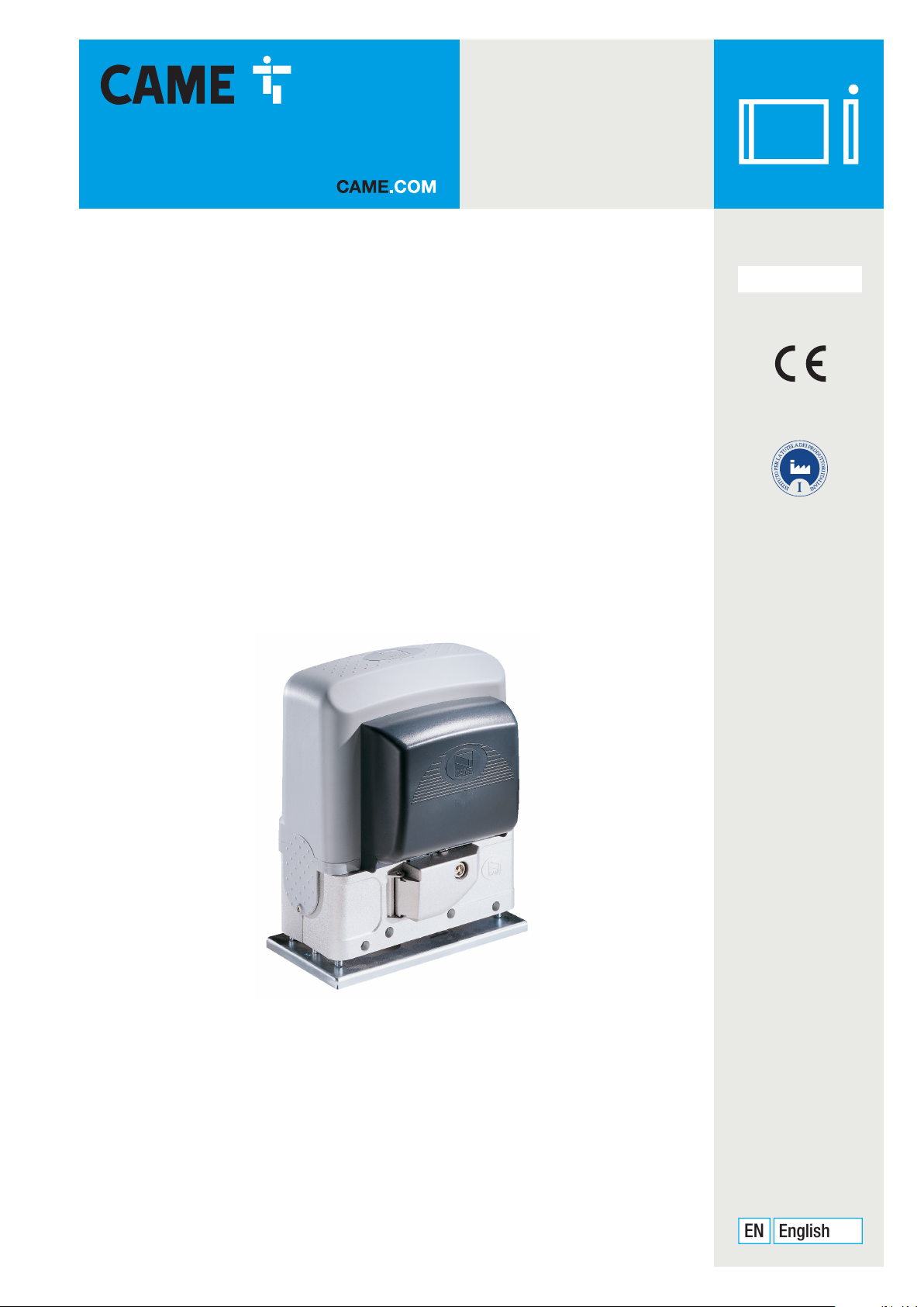
Sliding gate operator
EN
English
BK series
FA01161-EN
BK-800 / 1200 / 1800 / 2200
1210 / 1810 / 2210
INSTALLATION OPERATION AND MAINTENANCE MANUAL
Page 2
Original instructions
-
Manual FA01161- E N - 08/2018 - © CAME S.p.A. - The contents of this manual may change, at any time, and without notice.
Page 3
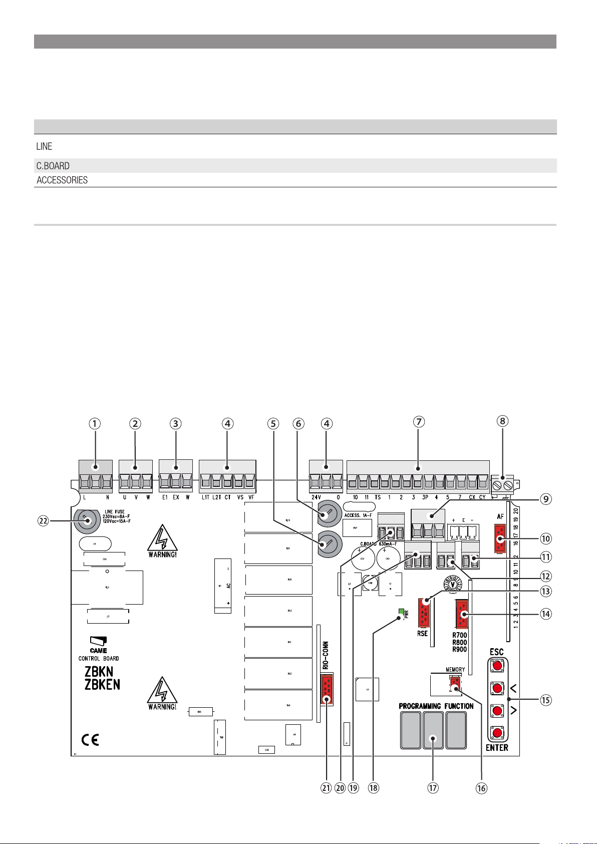
ELECTRICAL CONNECTIONS
Warning! Before doing any work on the control board, cut off the mains power supply, and disconnect any batteries.
⚠
The functions on the input and output contacts, the time settings and user management, are set and viewed on the graphic display.
All wiring connections are quick-fuse protected.
Fuses ZBKN - ZBKEN
- Line
- Card
- Accessories
DESCRIPTION OF PARTS
1. Power supply terminals
2. Terminal for gearmotors
3. Terminals for signaling devices
4. Transformer terminals
5. Control-board fuse
6. Accessories fuse
7. Terminals for control and safety devices
8. Antenna terminal
9. Terminals for limit-switch micro-switches
10. AF card connector
11. Terminals for transponder selector
12. Keypad selector terminal
13. RSE board connector
14. Connector for the R700/R800/900 cards
15. Programming buttons
16. Memory roll board connector
17. Display
18. Power supply on warning LED
19. Terminals for paired of CRP connection
20. Terminals for the RGP1 module
21. Connector for the RIO-CONN card
22. Line fuse
8 A-F (230 V AC)
15 A-F (120 V AC)
630 mA-F
1 A-F
Original instructions
-
Manual FA01161- E N - 08/2018 - © CAME S.p.A. - The contents of this manual may change, at any time, and without notice.
Page 4
FC FA F
+ E -
+ E -
+ STB -
24V 0
10 11 TS 1 2 3 3P 4 5 7 CX CY CZ
A B GND
+ STB -
10 11 TS 1 2 3 3P 4 5 7 CX CY CZ
A B GND
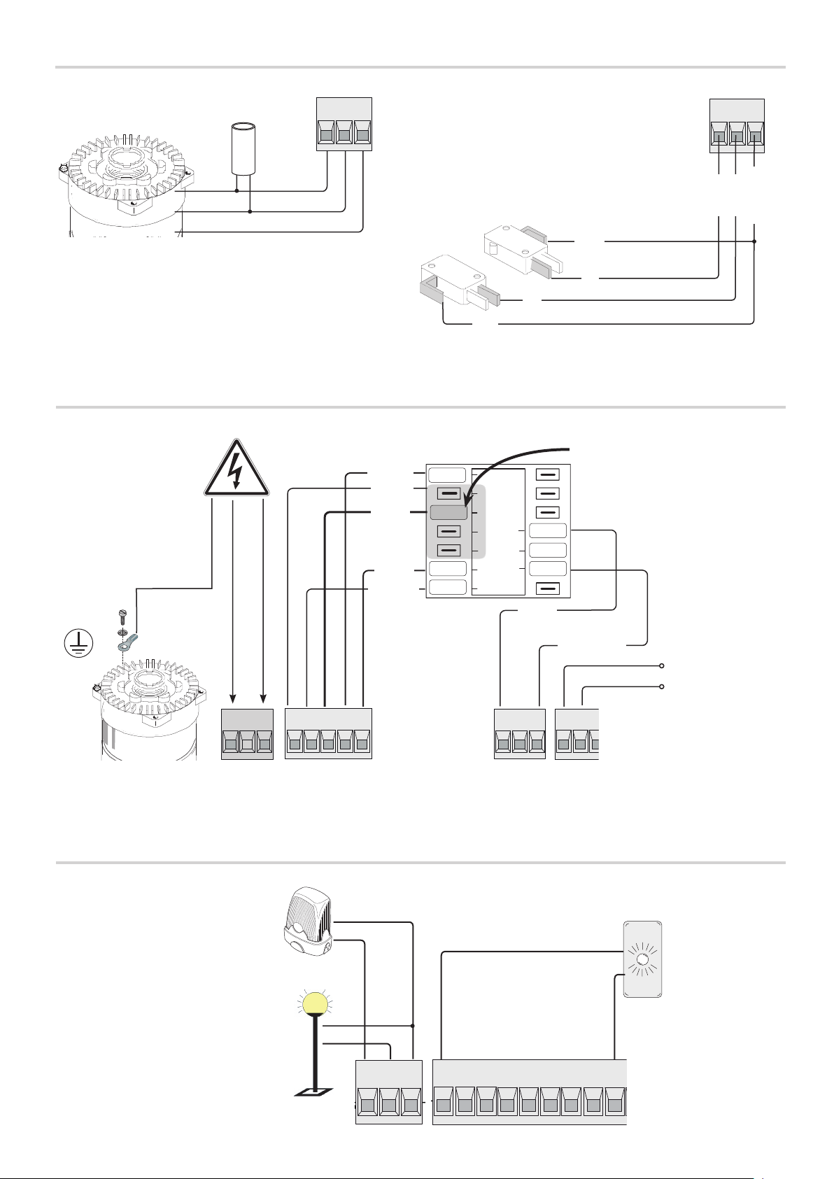
FACTORY WIRING
POWER SUPPLY
120 / 230 V AC 50/60 Hz
Original instructions
-
Condenser230V (AC) Gearmotor
U V W
FC FA F
Closing limit-switch
micro-switch
RED
WHITE
ORANGE
COM
Opening limit-switch
micro-switch
NC
NC
COM
To vary the motor torque, move
the shown faston to one of the four
Red
Gray
Black
White
Brown
SP
4
3
2
1
FR
0
positions; from 1 (min.) to 4 (max.).
24
17
0
Blue
L N
SIGNALING DEVICES
Flashing light connection output (contact
rated at: 230 V AC - 25 W max).
Additional light connection output (contact
rated at: 230 V - 60 W max).
See function F18.
L1T L2T CT VS VF
CAME
24V 0
Orange
Accessories power
supply output 24 V
AC, max 20 W.
10 11
Gate open signal
output (contact rated
at: 24 V AC - 3 W
max).
See function F10.
Manual FA01161- E N - 08/2018 - © CAME S.p.A. - The contents of this manual may change, at any time, and without notice.
E1 EX W
Page 5
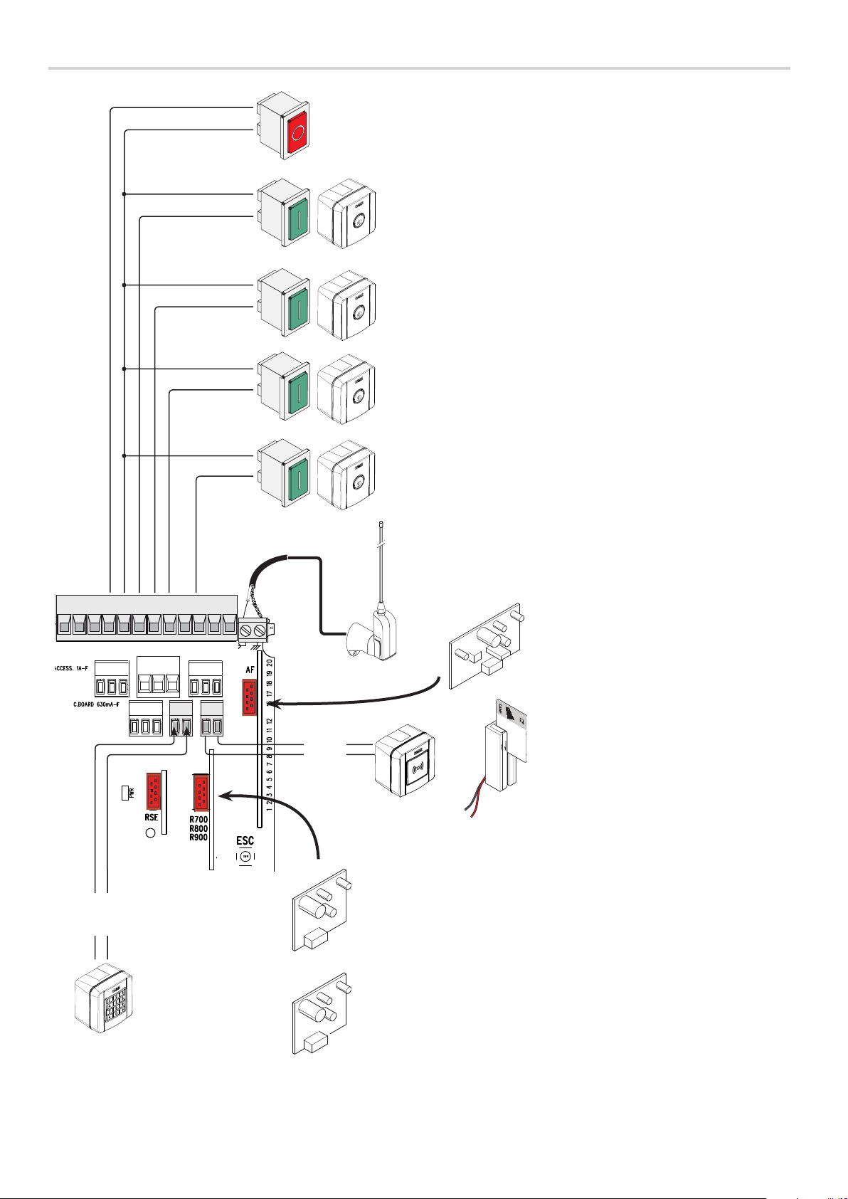
R700
R800
CONTROL DEVICES
STOP button (NC contact). For stopping the gate while excluding automatic
closing. To resume movement either press the control button or any other
control device.
Activate the F1 programming function. If the button is no used, leave
this function deactivated.
OPEN ONLY function from control device with NO contact.
Warning: in MAINTAINED ACTION mode, the control device must be connected
to 2-3.
PARTIAL OPENING function from control device (NO contact)
ONLY CLOSE function from control device (NO contact).
Warning: in MAINTAINED ACTION mode, the control device must be connected
to 2-4.
OPEN-CLOSE-INVERT function (step-step) from control device (NO contact).
Alternatively, from the functions programming you can activate the single
command OPEN-STOP-CLOSE-STOP (sequential).
See function F7.
10 11 TS 1 2 3 3P 4 5 7 CX CY
A B
S1 GND
BLUE
WHITE
BLACK
RED
Antenna with RG58 cable for remote control.
Fit either theAF43S or AF868 card for
controlling the gate via a transmitter.
AF
ACCESS CONTROL
Transponder or card reader.
Fit the R700 coding card to recognized
the transponder or the card reader.
Original instructions
-
Fitthe R800 decoding card so that the
keypad selector can be recognized.
Keypad selector.
WARNING! For the system to work properly, before fitting any snap-in card (e.g. the AF R800), you MUST CUT OFF THE MAIN POWER
SUPPLY and remove any batteries.
Manual FA01161- E N - 08/2018 - © CAME S.p.A. - The contents of this manual may change, at any time, and without notice.
Page 6
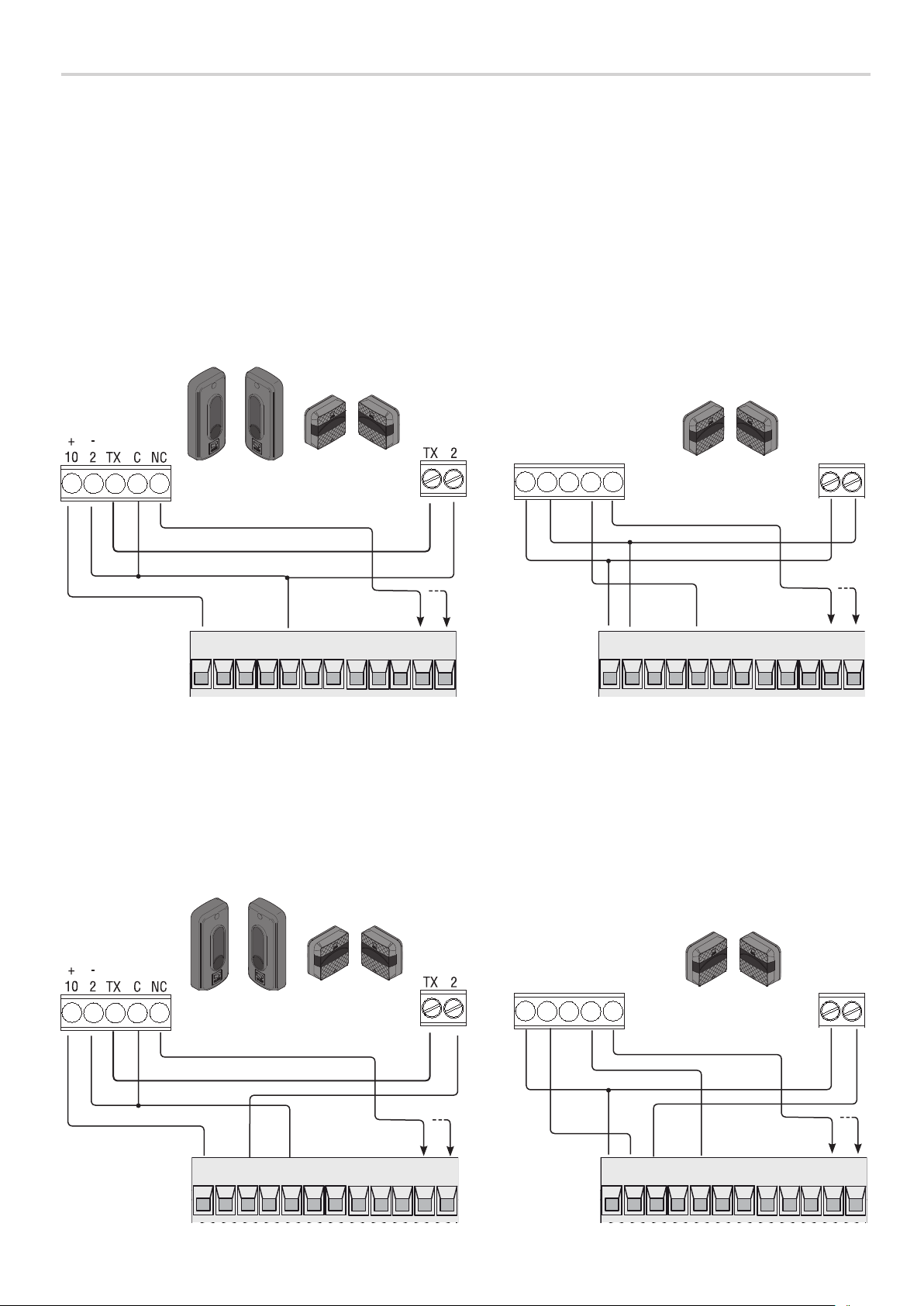
SAFETY DEVICES
Photocells
Configure contact CX or CY (NC), safety input for photocells.
See F2 (CXinput) or F3 (CY input) set to:
- C1 reopening during closing. When the gate is closing, opening the contact triggers the inversion of movement until the gate is fully open again;
- C2 closing during opening. When the gate is opening, opening the contact triggers the inversion of movement until the gate is completely closed.
- C3 partial stop. Stopping of the gate, if it is moving, with consequent automatic closing (if the automatic closing function has been entered);
- C4 obstruction wait. Stopping of the gate, if it is moving, which resumes movement once the obstruction is removed.
If contacts CX and CY are not used they should be deactivated during programming.
RX TX
RX TX
+
NO C NC
-
DIR DELTA-S
Original instructions
-
Photocells (safety test)
At each opening and closing command, the control board checks the efficacy of the safety devices (such as, photocells).
Any malfunction inhibits any command and the display will show the Er4 wording.
Enable function F5 in programming.
10 11 TS 1 2 3 3P 4 5 7 CX CY
10 11 TS 1 2 3 3P 4 5 7 CX CY
+ -
DELTA
RX TX
DIR DELTA-S
10 11 TS 1 2 3 3P 4 5 7 CX CY
Manual FA01161- E N - 08/2018 - © CAME S.p.A. - The contents of this manual may change, at any time, and without notice.
RX TX
+
NO C NC
-
DELTA
10 11 TS 1 2 3 3P 4 5 7 CX CY
+ -
Page 7
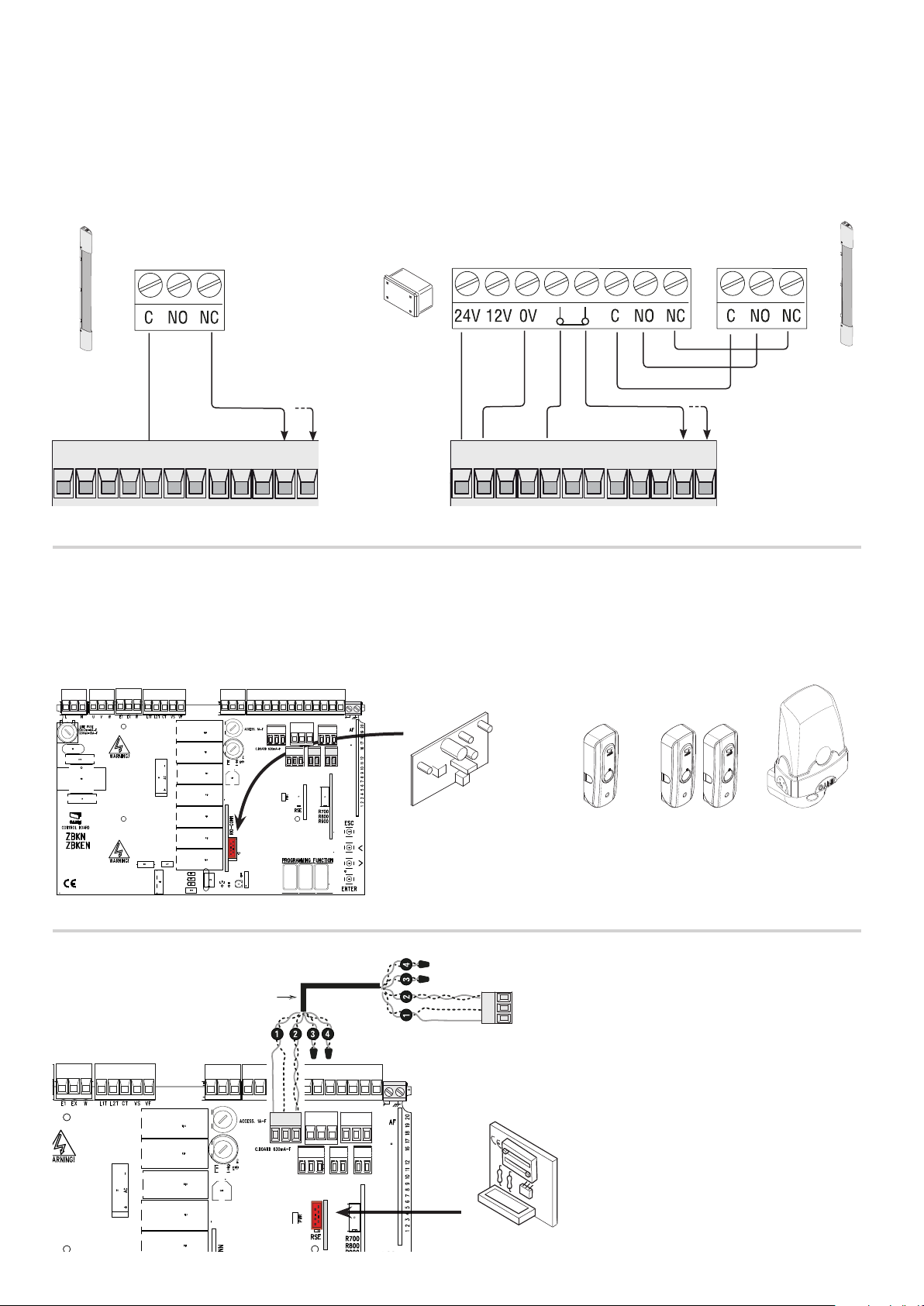
RIO-CONN
Sensitive Safety Edges
Configure contact CX or CY (NC), safety input for sensitive safety-edges.
See F2 (CXinput) or F3 (CY input) set to:
- C7 (sensitive safety edges with clean contact) or r7 (sensitive safety edges with 8K2 resistance), reopening during closing. When the gate is closing,
opening the contact triggers the inversion of movement until the gate is fully open again;
- edges with clean contact) or r8 (sensitive safety-edges with (8K2 resistive inputs), reclosing during opening. When the gate is opening, opening
the contact triggers the inversion of movement until the gate is completely closed.
If unused, contacts CX and CY should be deactivated during programming.
DFWN
10 11 TS 1 2 3 3P 4 5 7 CX CY
RIO WIRELESS DEVICES
Fit the RIO-CONN card into the corresponding connector on the control board.
Set the function to associate to the wireless device (F65, F66, F67 and F68).
Configure the RIO-EDGE, RIO-CELL and RIO-LUX wireless devices by following the indications shown in the folder enclosed with each accessory.
If the devices are not configured with the RIO-CONN card, the E18 error message appears on the display.
If there are any radio-frequency disturbances to the system, the wireless system will inhibit the normal operation of the operator, and this error
⚠
will show up on the display as E17.
10 11 TS 1 2 3 3P 4 5 7 CX CY
connnections
DFWN with DFI card for controlling the
Original instructions
-
PAIRED OPERATION OR CRP (CAME REMOTE PROTOCOL)
UTP CAT 5
A B GND
RIO-CONN
RIO-CELLRIO-EDGE RIO-LUX
Serial RS485 connection via CRP (Came Remote Protocol)
or for paired operation (see chapter called PAIRED
A B GND
CONNECTIONS AND OPERATION).
Fit the RSE card.
WARNING! For the system to work properly, before
fitting the control board, you MUST CUT OFF
RSE
THE POWER MAINS and remove any emergency
batteries.
Manual FA01161- E N - 08/2018 - © CAME S.p.A. - The contents of this manual may change, at any time, and without notice.
Page 8
1”
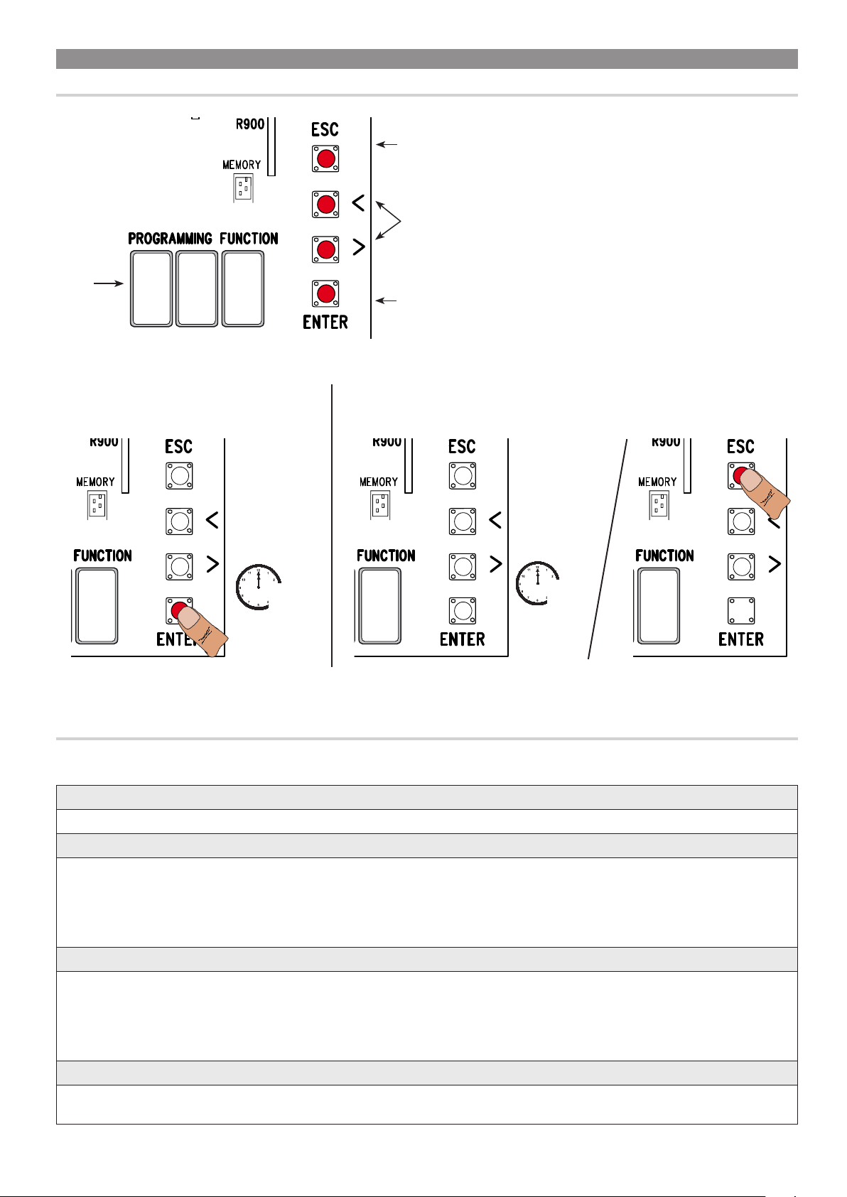
PROGRAMMING
DESCRIPTION OF THE COMMANDS
The ESC button is for:
- exiting menus;
- cancelling changes;
{
- stopping the gate (only when testing).
The < > keys are for:
- moving from one item to another;
{
- increasing or decreasing a value;
- opening and closing the gate (only when testing).
Display
8
To enter the menu, keep the ENTER button
pressed for at least one second.
Original instructions
-
8 8
8
The ENTER key is for:
- entering menus;
{
- confirming or memorizing set values.
To exit the menu, wait 10 seconds or press ESC.
10”
8
8
FUNCTIONS MENU
Warning! When programming, the gate must not be operating.
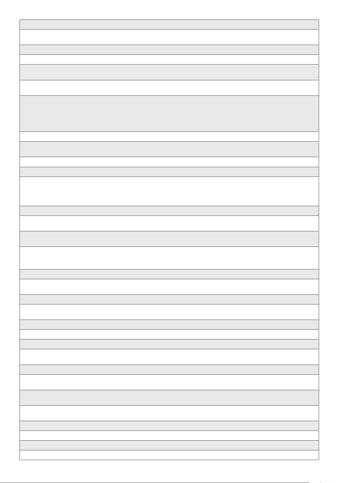
F1 Total stop (1-2) OFF (default) / ON
NC input – Gate stop that excludes any automatic closing; to resume movement, use the control device. The safety device is inserted into (1-2).
F2 Input (2-CX) OFF (default) / 1 = C1 / 2 = C2 / 3 = C3 / 4 = C4 / 7 = C7 / 8 = C8 / r7 = r7 / r8 = r8
NC input – Can associate: C1 = reopening during closing by photocells, C2 = reclosing during opening by photocells, C3 = partial stop, C4 =
obstruction wait, C7 = reopening during closing by sensitive safety-edges (with clean contact), C8 = reclosing during opening by sensitive safetyedges (with clean contact), r7 = reopening during closing for sensitive safety edges (8K2 resistive input), - r8 = reclosing during opening for
sensitive safety edges (8K2 resistive input).
The C3 Partial stop function only appears if the F 19 Automatic closing time function is activated.
F3 Input (2-CY) OFF (default) / 1 = C1 / 2 = C2 / 3 = C3 / 4 = C4 / 7 = C7 / 8 = C8 / r7 = r7 / r8 = r8
NC input – Can associate: C1 = reopening during closing by photocells, C2 = reclosing during opening by photocells, C3 = partial stop, C4 =
obstruction wait, C7 = reopening during closing by sensitive safety-edges (with clean contact), C8 = reclosing during opening by sensitive safetyedges (with clean contact), r7 = reopening during closing for sensitive safety edges (8K2 resistive input), - r8 = reclosing during opening for
sensitive safety edges (8K2 resistive input).
The C3 Partial stop function only appears if the F 19 Automatic closing time function is activated.
F5 Safety test OFF (default) / 1 = CX / 2 = CY / 4 = CX+CY
After every opening or closing command, the board will check whether the photocells are working properly.
The safety test is always active for wireless devices.
Manual FA01161- E N - 08/2018 - © CAME S.p.A. - The contents of this manual may change, at any time, and without notice.
Page 9
F6 Maintained action OFF (default) / ON
The gate opens and closes by keeping the button pressed. Opening button on contact 2-3 and closing button on contact 2-4. All other control
devices, even radio-based ones, are excluded.
F7 Command (2-7) 0 = Step-step (default) / 1 = Sequential
From the control device connected to 2-7 it performs the step-step (open-close-invert) or sequential (open-stop-close-stop) command.
F9 Obstruction detection with motor
OFF (default) / ON
idle
With the gate closed, opened or totally stopped, the gearmotor stays idle if the safety devices, that is, photocells or sensitive safety-edges detect
an obstruction.
F10 Gate-open signal output 0 = On when the barrier is open and moving (default) /
1 = during openings it flashes intermittently each half second
, and during closings it flashes intermittently each
second. It stays on steadily
when the barrier is open, o or when it s closed.
It signals the gate status. The signal device is connected to contact 10-5.
F14 Sensor type selection 0 = control with transponder sensor or magnetic card reader.
1 = command with keypad selector (default).
Setting the type of accessory for controlling the operator.
F18 Additional light OFF (default) / 1 = Cycle / 2 = Courtesy
Extra light connection input on EX-W.
Outdoor light for additional visibility in the drive way.
Cycle: it stays lit from the moment the gate starts opening until it completely closes, including the automatic closing waiting time.
Courtesy: it stays on for an adjustable time of between 60 and 180 seconds. For adjusting the time, see function [F25].
F19 Automatic closing time OFF (default) / 1 = 1 second /… / 180 = 180 seconds
The automatic-closing wait starts when the opening limit switch point is reached and can be set to between 1 and 180 seconds. The automatic
closing does not activate if any of the safety devices trigger when an obstruction is detected, or after a total stop, or during a power outage.
F20 Automatic closing time after a
OFF / 1 = 1 second /…/ 10 = 10 seconds (default) /…/ 180 = 180 seconds
partial opening
The wait before the automatic closing starts after a partial opening command for an adjustable time of between 1 s and 180 s.
The automatic closing does not activate if any of the safety devices trigger when an obstruction is detected, or after a total stop, or during a power
outage.
F21 Preflashing time OFF (default) / 1 = 1 second /… / 10 = 10 seconds
Original instructions
-
Adjusting the pre-flashing time for the flashing light connected to E1-W, before each maneuver. The flashing time is adjustable from one to ten
seconds.
F25 Courtesy light time 60 = 60 seconds (default)/ 180 = 180 seconds
Additional light that stays on for the required time during the when the gate is opening or closing.
EX-W contact output. It is adjustable between 60 seconds and 180 seconds.
F49 Managing serial connection OFF (default) / 1 = Paired / 3 = CRP
To enable the paired operating mode or the CRP (Came Remote Protocol).
F50 Save data OFF (default) / ON
Saving users and saved settings in memory roll.
This function only appears if a memory roll has been fitted into the control board.
F51 Read data OFF (default) / ON
Uploading data saved in memory roll.
This function only appears if a memory roll has been fitted into the control board.
F52 Passing parameter in paired
OFF (default) / ON
mode
Uploading settings from Master to Slave.
It appears only if function [F49] is set to Paired.
F54 Opening direction OFF = Opening left (default) / ON = Opening right
For setting the gate opening direction.
F56 Peripheral number 1 ----> 255
To set the peripheral's number from 1 to 255 for each control board when you have a system with several operators.
Manual FA01161- E N - 08/2018 - © CAME S.p.A. - The contents of this manual may change, at any time, and without notice.
Page 10
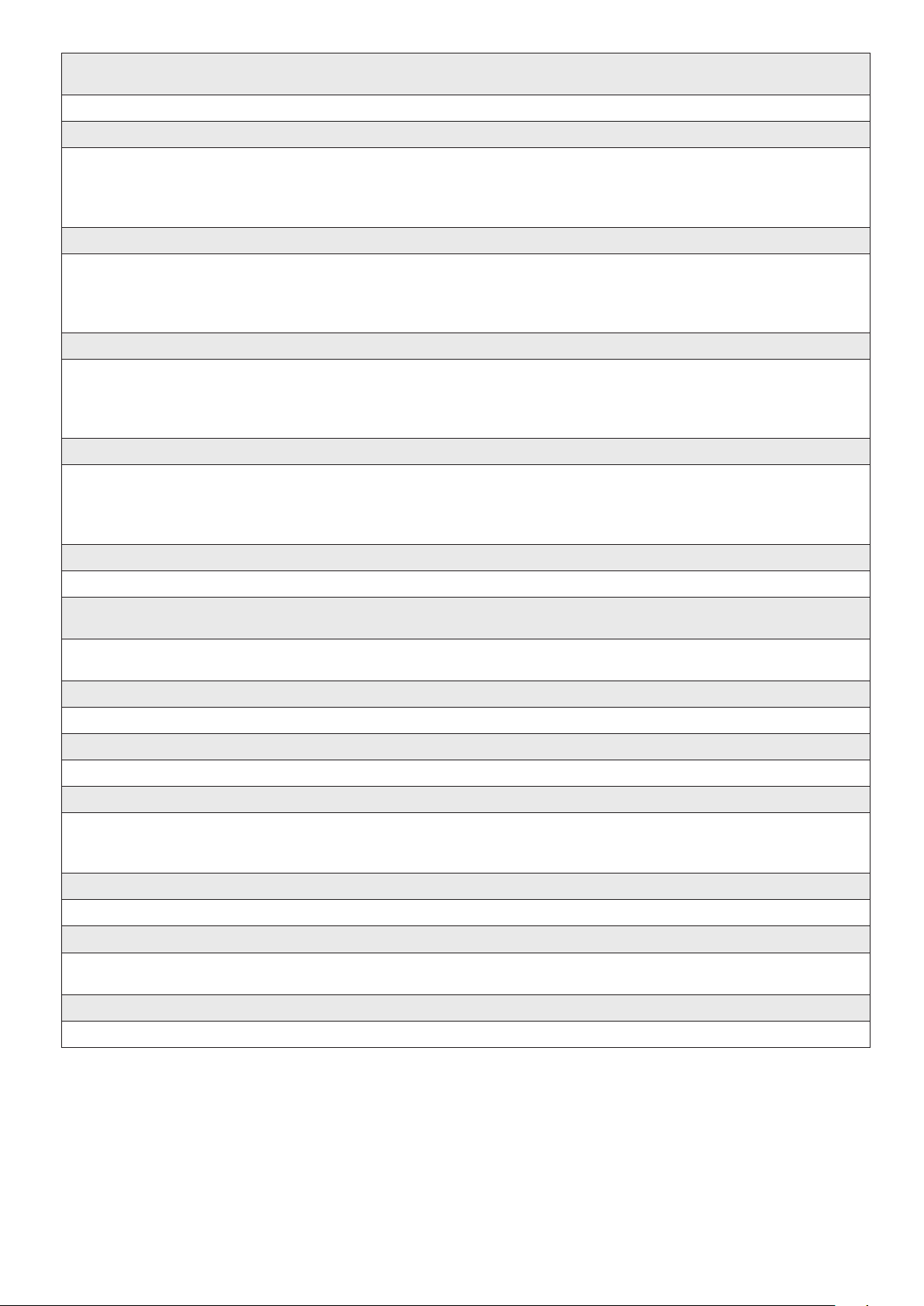
F63 Change COM speed 0 = 1200 Baud / 1 = 2400 Baud / 2 = 4800 Baud / 3 = 9600 Baud / 4 = 14400 Baud / 5 = 19200
Baud / 6 = 38400 Baud (default) / 7 = 57600 Baud / 8 = 115200 Baud
For setting the communication speed used in the CRP (Came Remote Protocol) connection system.
F65 Wireless input RIO-EDGE [T1] OFF (default) / P0 = P0 / P7 = P7 / P8 = P8
RIO-EDGE wireless safety device associated to a function of choice among those available: P0= stop gate and exclude any automatic closing; to
resume movement, use the control device, P7 = reopening during closing, P8 = reclosing during opening.
For programming, see the instructions that come with the accessory.
This function only appears is the control board has been fitted with a RIO-CONN card.
F66 Wireless input RIO-EDGE [T2] OFF (default) / P0 = P0 / P7 = P7 / P8 = P8
RIO-EDGE wireless safety device associated to a function of choice among those available: P0= stop gate and exclude any automatic closing; to
resume movement, use the control device, P7 = reopening during closing, P8 = reclosing during opening.
For programming, see the instructions that come with the accessory.
This function only appears is the control board has been fitted with a RIO-CONN card.
F67 Wireless input RIO-CELL [T1] OFF (default) / P1 = P1 / P2 marked areas = P2 / P3 = P3 / P4 = P4
RIO-CELL is associated to any function chosen among those available: P1 = reopening during closing; P2 = reclosing during opening; P3 = partial
stop; P4 = obstruction wait.
For programming, see the instructions that come with the accessory.
This function only appears is the control board has been fitted with a RIO-CONN card.
F68 Wireless input RIO-CELL [T2] OFF (default) / P1 = P1 / P2 marked areas = P2 / P3 = P3 / P4 = P4
RIO-CELL is associated to any function chosen among those available: P1 = reopening during closing; P2 = reclosing during opening; P3 = partial
stop; P4 = obstruction wait.
For programming, see the instructions that come with the accessory.
This function only appears is the control board has been fitted with a RIO-CONN card.
F71 Partial opening time 5 = 5 seconds (default) /....... / 40 = 40 seconds
After an opening command from the button connected to 2-3P, the gate opens for an adjustable time of between five seconds and 40 seconds.
U 1 Entering a user 1 = Step-step command (open-close) / 2 = Sequential command (open-stop-close-stop) / 3 = Open
Original instructions
-
only command / 4 = Partial opening command
Entering up to 250 users and associating to each one a function of choice among those included. This must be done via transmitter or other control
device (see "ENTERING USERS WITH ASSOCIATED COMMAND paragraph).
U 2 Deleting a user
Deleting a single user
U 3 Deleting users OFF (default) / ON = Delete all users
Deleting all users.
U4 Code decoding 1 (default) / 2 / 3
For choosing the type of receiving control code: 1= all series / 2 = only Rolling Code series / 3 = only TWIN series
⚠ When you select a radio code, all saved transmitters will automatically be deleted.
The TWIN code lets you save multiple users with the same key, that is, key block.
A 4 Resetting parameters OFF (default) / ON
Attention! The default settings will be restored.
A 5 Counting maneuvers Number of maneuvers done
For viewing the number of maneuvers completed or for deleting them (001 = 100 maneuvers; 010 = 1,000 maneuvers; 100 = 10,000 maneuvers;
999 = 99,900 maneuvers; CSI = maintenance job)
H1 Version
View the firmware version.
Manual FA01161- E N - 08/2018 - © CAME S.p.A. - The contents of this manual may change, at any time, and without notice.
Page 11
COMMISSIONING
Once the electrical connections are done, have only skilled, qualified staff commission the operator into service.
Before continuing, make sure the area is free of any obstructions, and that there are mechanical, opening and closing gate stops in place.
Power up and begin configuring the system. Important!Start programming by first doing the following functions: OPENING DIRECTIONS (F54) and
TOTAL STOP (F1). Once the programming is done, verify that the operator and all the accessories are working properly.Use the < > keys to open
and close the gate and ESC to stop it.
After powering up the system, the first maneuver is always the opening. In this phase, the gate cannot be closed. You will need to wait for the gate
⚠
to completely open.
Immediately press the STOP button if any suspicious malfunctions, noises or vibrations occur in the system.
⚠
MANAGING USERS
When adding and deleting users, the flashing numbers appearing are those numbers that are available and usable to assign to a new user (max.
250 users).
Before registering the users, make sure the AF radio card is plugged into the connector (see the paragraph called CONTROL DEVICES).
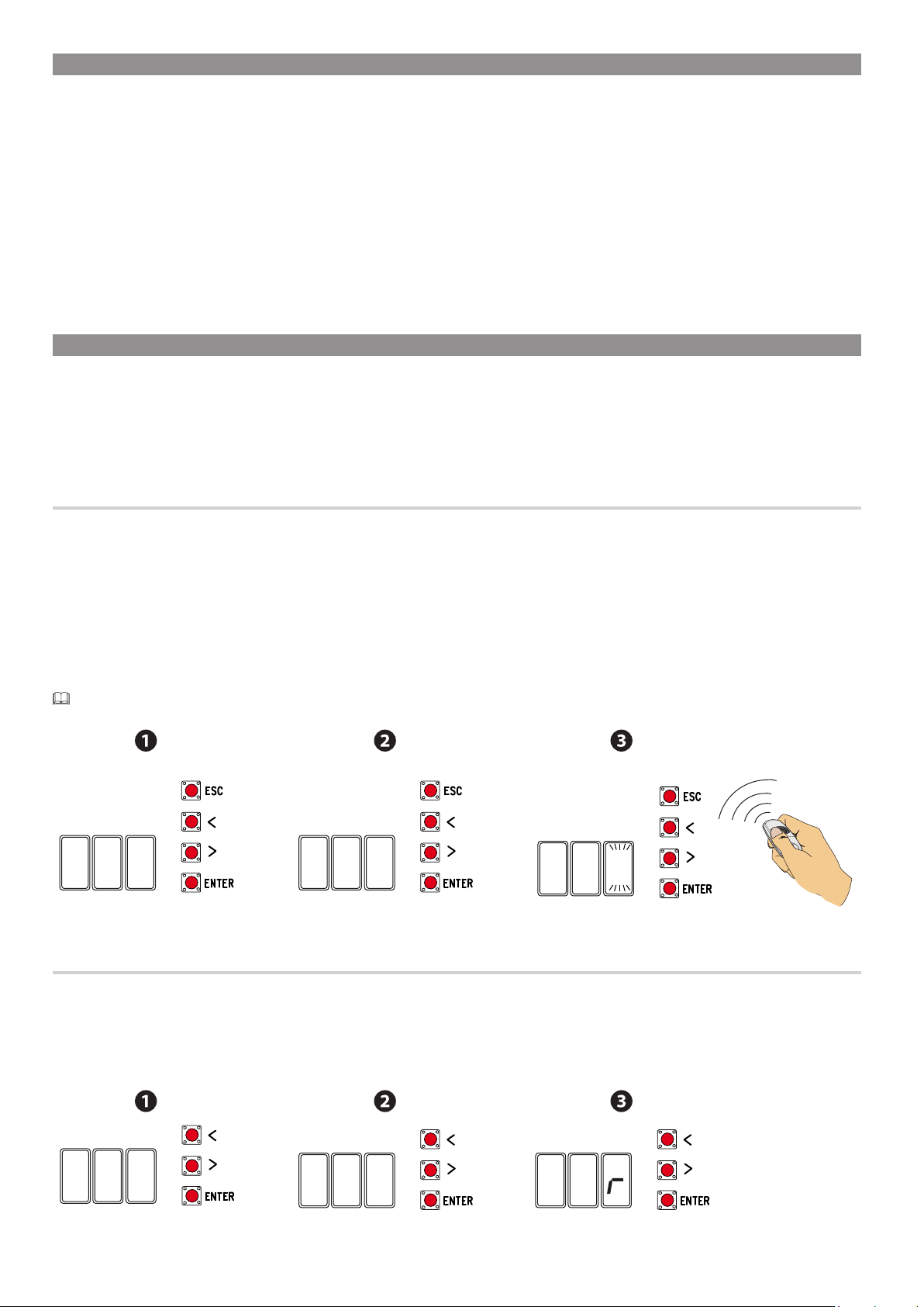
ENTERING USERS WITH AN ASSOCIATED COMMAND
❶ Select U1. Press ENTER to confirm.
❷ Select a command to associate to the user: The commands are:
- 1 = step-step (open-close);
- 2 = - sequential (open-stop-close-stop);
-3 = only open;
- 4 = partial opening/pedestrian.
Press ENTER to confirm...
❸ ... a number between 1 and 250 will start flashing for a few seconds. Send the code from the transmitter or other control device, such as, a
keypad selector or a transponder.
It flags the entered user associated to the number in the table LIST OF REGISTERED USERS.
iU 2
DELETING SINGLE USERS
5
Original instructions
-
❶ Select U2. Press ENTER to confirm.
❷ Use the arrow keys select the number of the user you wish to delete. Press ENTER to confirm...
❸ ... CLr will appear on the screen to confirm deletion.
2
2
2
l
Manual FA01161- E N - 08/2018 - © CAME S.p.A. - The contents of this manual may change, at any time, and without notice.
Page 12
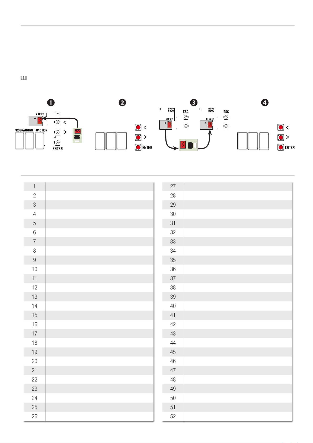
SAVING AND UPLOADING ALL DATA (USERS AND CONFIGURATION) WITH THE MEMORY ROLL
Procedure for memorizing all of the system's user and configuration data by using the Memory Roll, so they can be used with another control
board, even on another system.
Warning! Fitting and extracting the Memory Roll must be done with the mains power disconnected.
❶ Fit the Memory Roll into the its corresponding connector on the control board.
❷ Select F50 and press ENTER to confirm the saving of data in the Memory Roll.
❸ Extract the Memory roll and fit it into the connector of another control board.
❹ Select F51 and press ENTER to confirm the uploading of data into the Memory Roll.
After memorizing the data, it is best to remove the Memory roll.
Memory roll
5F
Memory
roll
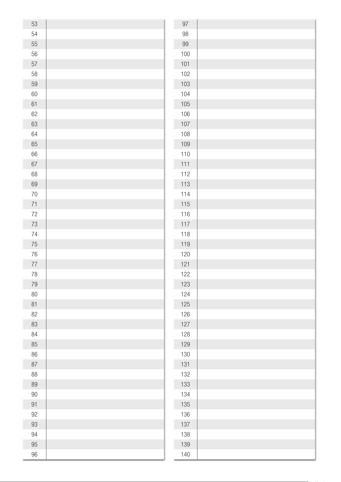
LIST OF REGISTERED USERS
0
5F
1
1
2
Original instructions
-
3
4
5
6
7
8
9
10
11
12
13
14
15
16
17
27
28
29
30
31
32
33
34
35
36
37
38
39
40
41
42
43
18
19
20
21
22
23
24
25
26
Manual FA01161- E N - 08/2018 - © CAME S.p.A. - The contents of this manual may change, at any time, and without notice.
44
45
46
47
48
49
50
51
52
Page 13
53
97
54
55
56
57
58
59
60
61
62
63
64
65
66
67
68
69
70
98
99
100
101
102
103
104
105
106
107
108
109
110
111
112
113
114
71
72
73
74
75
76
77
78
79
80
81
82
83
84
85
86
87
115
116
117
118
119
120
121
122
123
124
125
126
127
128
129
130
131
Original instructions
-
88
89
90
91
92
93
94
95
96
132
133
134
135
136
137
138
139
140
Manual FA01161- E N - 08/2018 - © CAME S.p.A. - The contents of this manual may change, at any time, and without notice.
Page 14
141
185
142
143
144
145
146
147
148
149
150
151
152
153
154
155
156
157
158
186
187
188
189
190
191
192
193
194
195
196
197
198
199
200
201
202
159
160
161
Original instructions
-
162
163
164
165
166
167
168
169
170
171
172
173
174
175
203
204
205
206
207
208
209
210
211
212
213
214
215
216
217
218
219
176
177
178
179
180
181
182
183
184
Manual FA01161- E N - 08/2018 - © CAME S.p.A. - The contents of this manual may change, at any time, and without notice.
220
221
222
223
224
225
226
227
228
Page 15
229
240
230
231
232
233
234
235
236
237
238
239
ERROR MESSAGES
The error messages are shown on the display.
E 4 Safety test error.
E 7 Insufficient working time.
241
242
243
244
245
246
247
248
249
250
E 8 Release hatch open.
E 9 Closing obstruction.
E 10 Opening obstruction.
E 11 Maximum number of obstructions detected.
E 14 Serial communication error
E 17 Wireless system error.
E 18 Missing wireless system configuration
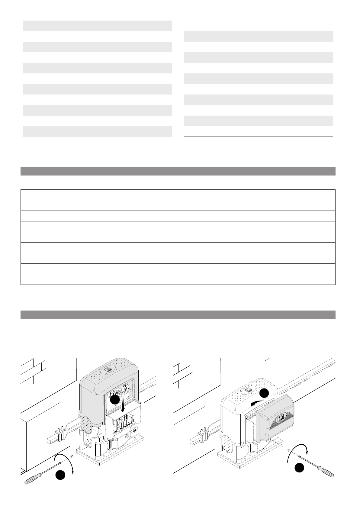
FINAL OPERATIONS
Once the operator is up and running and the users are registered, refit the covers without pinching any wires. Fasten them with
screws.
Original instructions
-
3
1
4
2
Manual FA01161- E N - 08/2018 - © CAME S.p.A. - The contents of this manual may change, at any time, and without notice.
Page 16
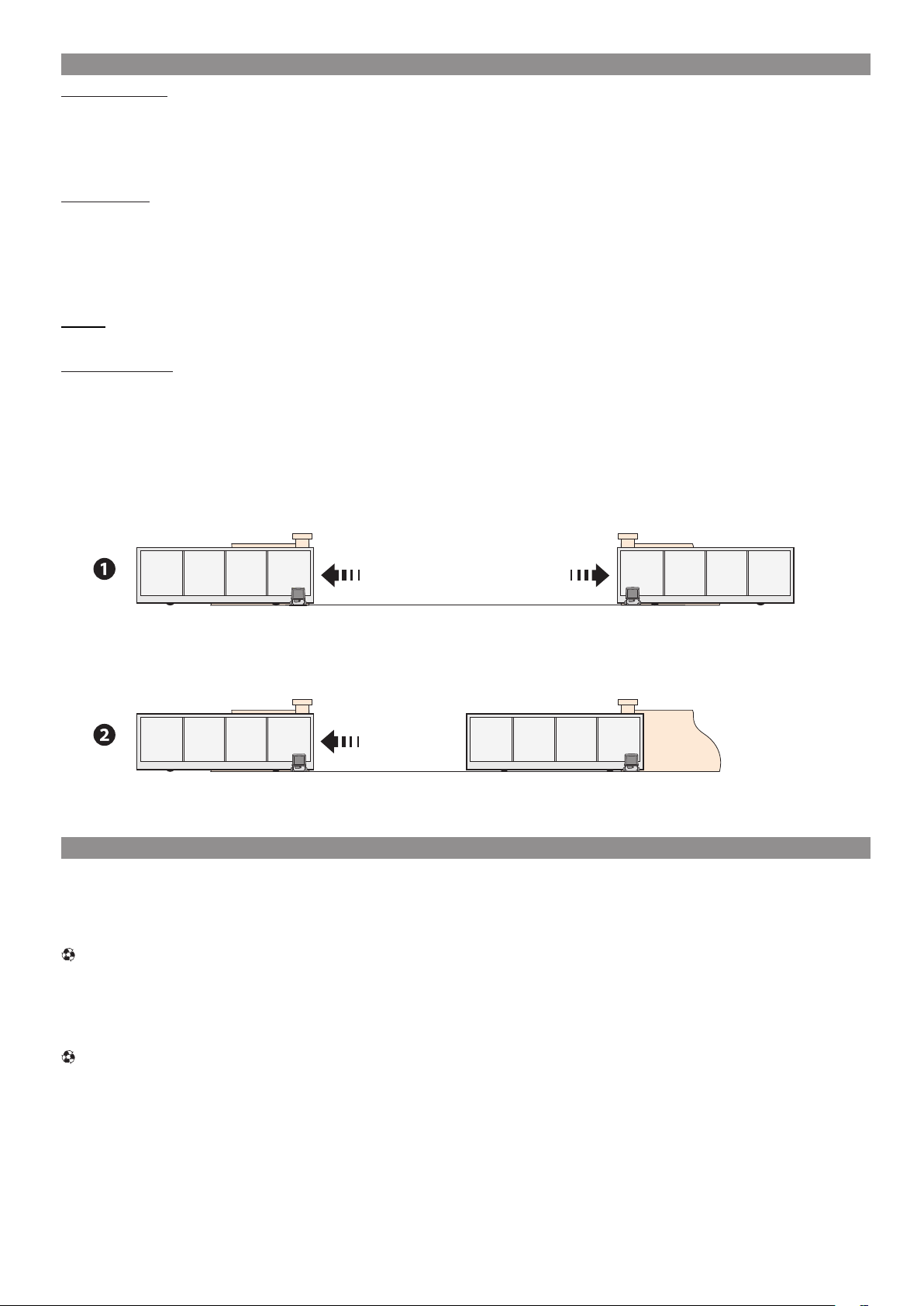
PAIRED CONNECTION AND OPERATION
Electrical wiring
Fit the RSE card (with the DIP-switches set to OFF) to the connector on the control panels of both operators.
Connect the two panels by using a CAT 5 (max 1,000 m type cable to terminals A-A / B-B / GND-GND, see paragraph called PAIRED
OPERATION.
Connect all of the control and safety devices on the MASTER operator's control panel.
Programming
Continue making the settings and adjustments only on the MASTER panel.
Start programming by first running the following functions:
- managing serial connection (F49);
- opening direction (F54);
- parameter exchange in paired mode (F52).
Saving
Execute the procedure, to add a user with an associated command, on the MASTER panel.
Operating modes
Either STEP-STEP or ONLY OPEN command. Both leaves open.
PARTIAL/PEDESTRIAN OPENING command. Only the MASTER operator's leaf opens.
For the types of command that can be selected and paired to users, see the ENTERING USERS WITH ASSOCIATED COMMANDS.
Original instructions
-
MASTER SLAVE
MASTER SLAVE
DISMANTLING AND DISPOSAL
CAME S.p.A. applies a certified Environmental Management System at its premises, which is compliant with the UNI EN ISO
☞
14001 standard to ensure the environment is safeguarded.
Please continue safeguarding the environment. At CAME we consider it one of the fundamentals of our operating and market
strategies. Simply follow these brief disposal guidelines:
DISPOSING OF THE PACKAGING
The packaging materials (cardboard, plastic, and so on) should be disposed of as solid household waste, and simply separated from
other waste for recycling.
Always make sure you comply with local laws before dismantling and disposing of the product.
DISPOSE OF RESPONSIBLY!
DISMANTLING AND DISPOSAL
Our products are made of various materials. Most of these (aluminum, plastic, iron, electrical cables) are classified as solid household
waste. They can be recycled by separating them before dumping at authorized city plants.
Whereas other components (control boards, batteries, transmitters, and so on) may contain hazardous pollutants.
These must therefore be disposed of by authorized, certified professional services.
Before disposing, it is always advisable to check with the specific laws that apply in your area.
DISPOSE OF RESPONSIBLY!
Manual FA01161- E N - 08/2018 - © CAME S.p.A. - The contents of this manual may change, at any time, and without notice.
Page 17

Original instructions
-
CAME S.p.A.
Via Martiri Della Libertà, 15
31030 Dosson di Casier - Treviso - Italy
tel. (+39) 0422 4940 - fax. (+39) 0422 4941
Manual FA01161- E N - 08/2018 - © CAME S.p.A. - The contents of this manual may change, at any time, and without notice.
 Loading...