

CAME BK Series, BK-1800, BK-800, BK-1810, BK-1210 Installation, Operation And Maintenance Manual
...
Sliding gate operator
EN
English
BK series
FA01161-EN
BK-800 / 1200 / 1800 / 2200
1210 / 1810 / 2210
INSTALLATION OPERATION AND MAINTENANCE MANUAL
Original instructions
-
Manual FA01161- E N - 08/2018 - © CAME S.p.A. - The contents of this manual may change, at any time, and without notice.
ELECTRICAL CONNECTIONS
Warning! Before doing any work on the control board, cut off the mains power supply, and disconnect any batteries.
⚠
The functions on the input and output contacts, the time settings and user management, are set and viewed on the graphic display.
All wiring connections are quick-fuse protected.
Fuses ZBKN - ZBKEN
- Line
- Card
- Accessories
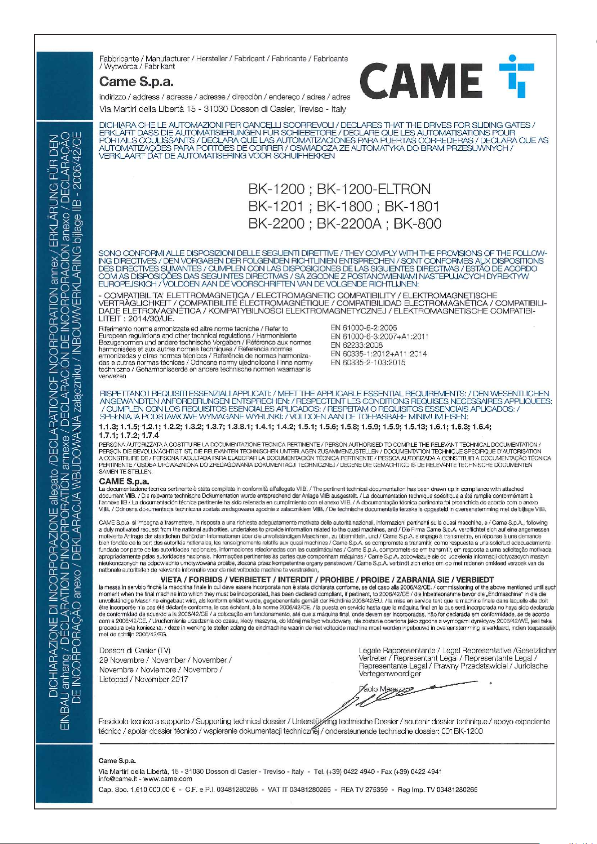
DESCRIPTION OF PARTS
1. Power supply terminals
2. Terminal for gearmotors
3. Terminals for signaling devices
4. Transformer terminals
5. Control-board fuse
6. Accessories fuse
7. Terminals for control and safety devices
8. Antenna terminal
9. Terminals for limit-switch micro-switches
10. AF card connector
11. Terminals for transponder selector
12. Keypad selector terminal
13. RSE board connector
14. Connector for the R700/R800/900 cards
15. Programming buttons
16. Memory roll board connector
17. Display
18. Power supply on warning LED
19. Terminals for paired of CRP connection
20. Terminals for the RGP1 module
21. Connector for the RIO-CONN card
22. Line fuse
8 A-F (230 V AC)
15 A-F (120 V AC)
630 mA-F
1 A-F
Original instructions
-
Manual FA01161- E N - 08/2018 - © CAME S.p.A. - The contents of this manual may change, at any time, and without notice.
FC FA F
+ E -
+ E -
+ STB -
24V 0
10 11 TS 1 2 3 3P 4 5 7 CX CY CZ
A B GND
+ STB -
10 11 TS 1 2 3 3P 4 5 7 CX CY CZ
A B GND
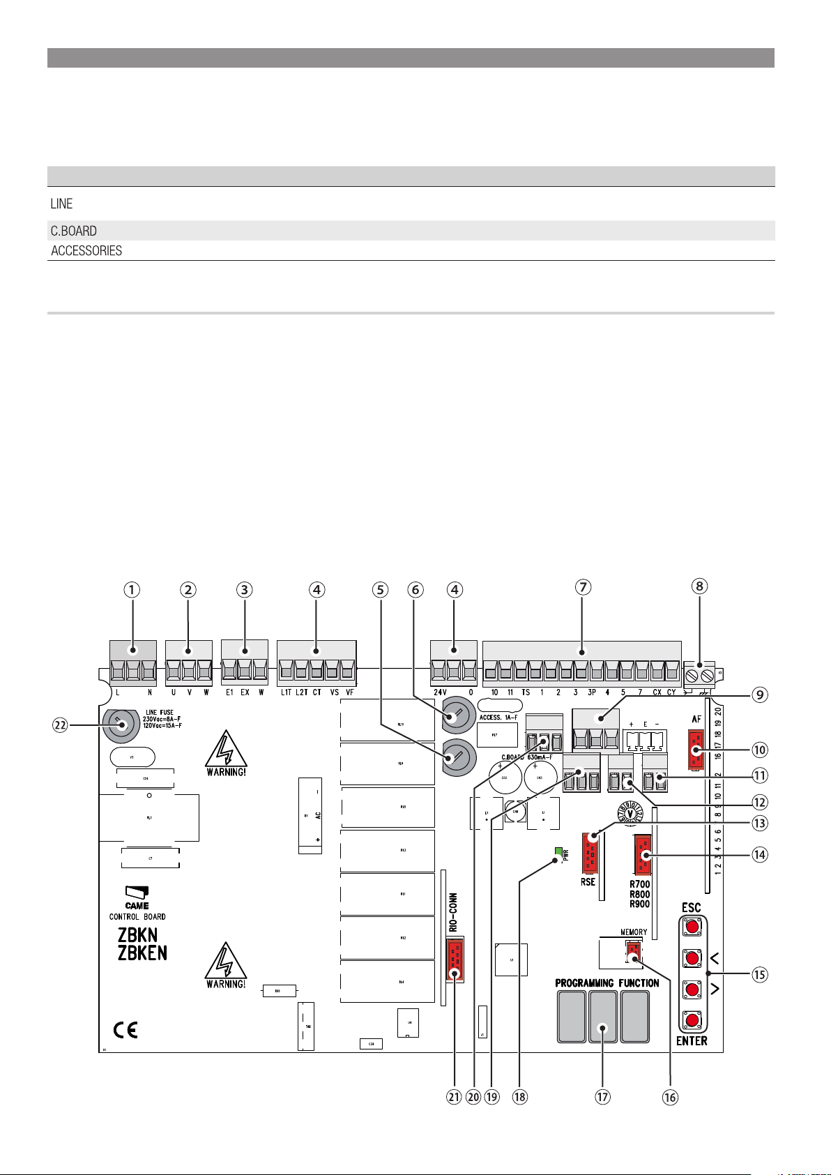
FACTORY WIRING
POWER SUPPLY
120 / 230 V AC 50/60 Hz
Original instructions
-
Condenser230V (AC) Gearmotor
U V W
FC FA F
Closing limit-switch
micro-switch
RED
WHITE
ORANGE
COM
Opening limit-switch
micro-switch
NC
NC
COM
To vary the motor torque, move
the shown faston to one of the four
Red
Gray
Black
White
Brown
SP
4
3
2
1
FR
0
positions; from 1 (min.) to 4 (max.).
24
17
0
Blue
L N
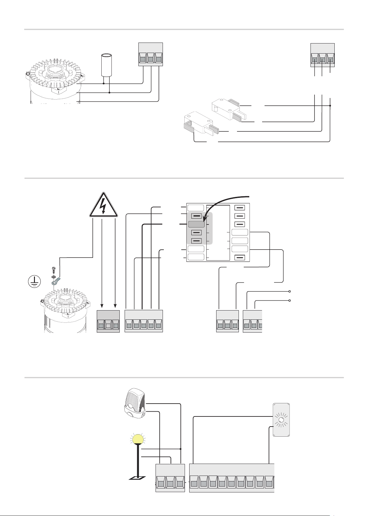
SIGNALING DEVICES
Flashing light connection output (contact
rated at: 230 V AC - 25 W max).
Additional light connection output (contact
rated at: 230 V - 60 W max).
See function F18.
L1T L2T CT VS VF
CAME
24V 0
Orange
Accessories power
supply output 24 V
AC, max 20 W.
10 11
Gate open signal
output (contact rated
at: 24 V AC - 3 W
max).
See function F10.
Manual FA01161- E N - 08/2018 - © CAME S.p.A. - The contents of this manual may change, at any time, and without notice.
E1 EX W
R700
R800
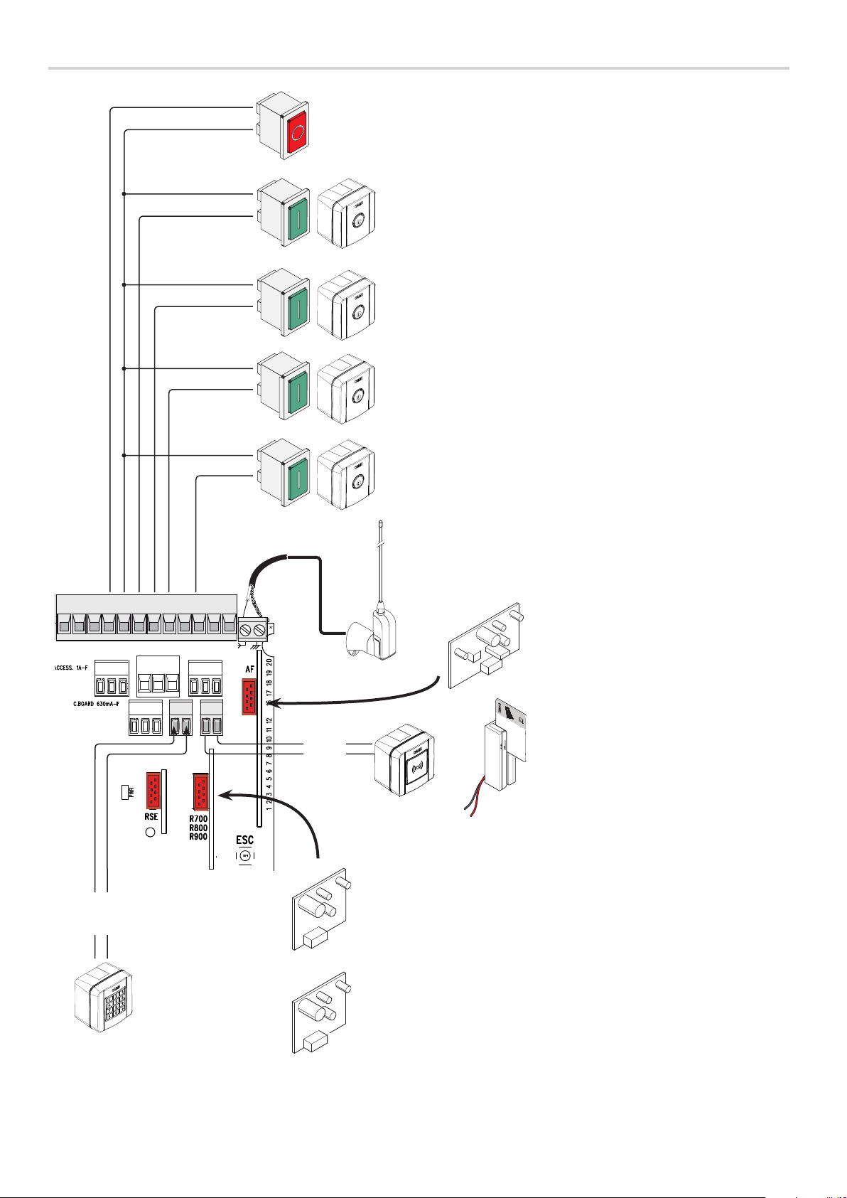
CONTROL DEVICES
STOP button (NC contact). For stopping the gate while excluding automatic
closing. To resume movement either press the control button or any other
control device.
Activate the F1 programming function. If the button is no used, leave
this function deactivated.
OPEN ONLY function from control device with NO contact.
Warning: in MAINTAINED ACTION mode, the control device must be connected
to 2-3.
PARTIAL OPENING function from control device (NO contact)
ONLY CLOSE function from control device (NO contact).
Warning: in MAINTAINED ACTION mode, the control device must be connected
to 2-4.
OPEN-CLOSE-INVERT function (step-step) from control device (NO contact).
Alternatively, from the functions programming you can activate the single
command OPEN-STOP-CLOSE-STOP (sequential).
See function F7.
10 11 TS 1 2 3 3P 4 5 7 CX CY
A B
S1 GND
BLUE
WHITE
BLACK
RED
Antenna with RG58 cable for remote control.
Fit either theAF43S or AF868 card for
controlling the gate via a transmitter.
AF
ACCESS CONTROL
Transponder or card reader.
Fit the R700 coding card to recognized
the transponder or the card reader.
Original instructions
-
Fitthe R800 decoding card so that the
keypad selector can be recognized.
Keypad selector.
WARNING! For the system to work properly, before fitting any snap-in card (e.g. the AF R800), you MUST CUT OFF THE MAIN POWER
SUPPLY and remove any batteries.
Manual FA01161- E N - 08/2018 - © CAME S.p.A. - The contents of this manual may change, at any time, and without notice.
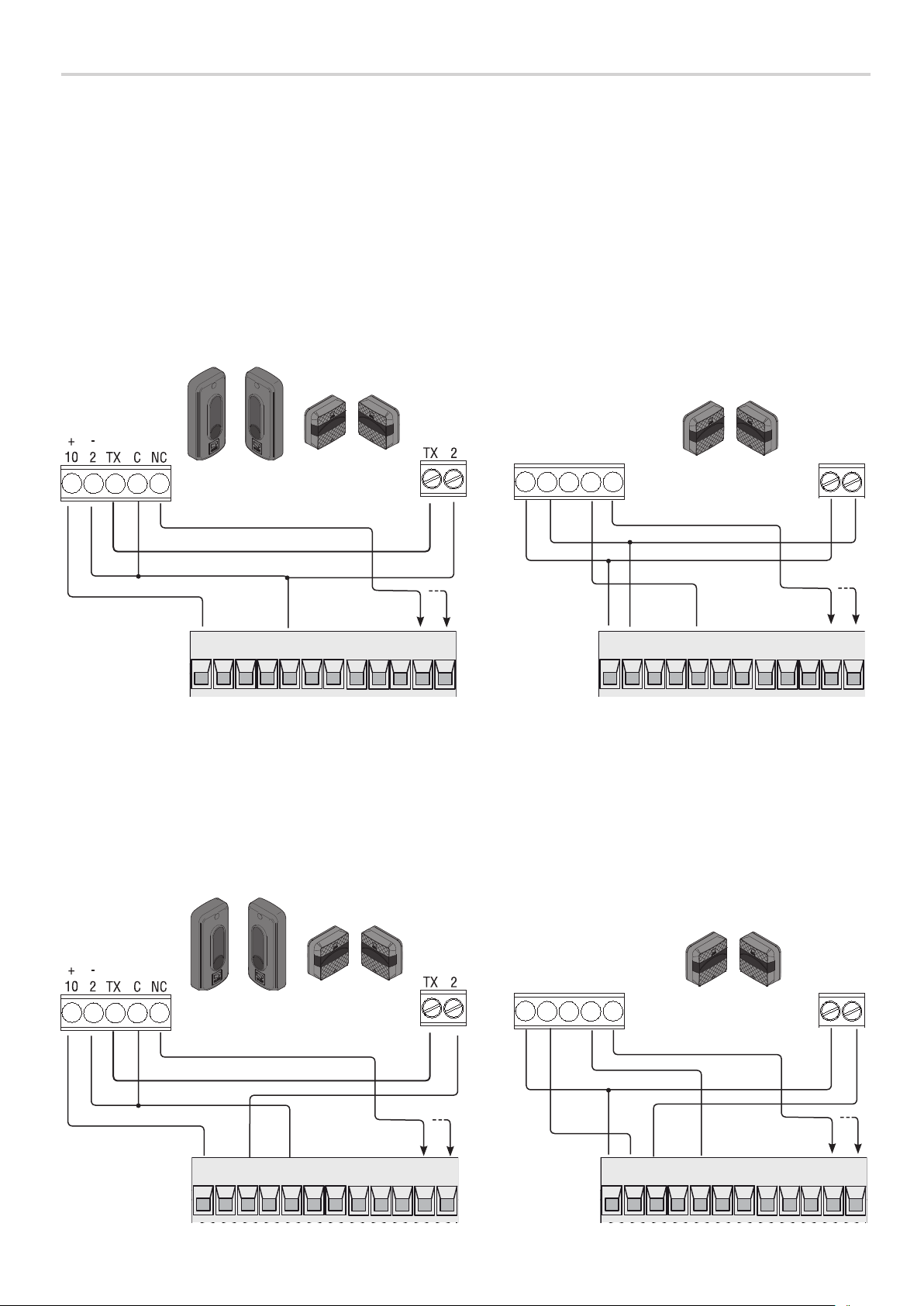
SAFETY DEVICES
Photocells
Configure contact CX or CY (NC), safety input for photocells.
See F2 (CXinput) or F3 (CY input) set to:
- C1 reopening during closing. When the gate is closing, opening the contact triggers the inversion of movement until the gate is fully open again;
- C2 closing during opening. When the gate is opening, opening the contact triggers the inversion of movement until the gate is completely closed.
- C3 partial stop. Stopping of the gate, if it is moving, with consequent automatic closing (if the automatic closing function has been entered);
- C4 obstruction wait. Stopping of the gate, if it is moving, which resumes movement once the obstruction is removed.
If contacts CX and CY are not used they should be deactivated during programming.
RX TX
RX TX
+
NO C NC
-
DIR DELTA-S
Original instructions
-
Photocells (safety test)
At each opening and closing command, the control board checks the efficacy of the safety devices (such as, photocells).
Any malfunction inhibits any command and the display will show the Er4 wording.
Enable function F5 in programming.
10 11 TS 1 2 3 3P 4 5 7 CX CY
10 11 TS 1 2 3 3P 4 5 7 CX CY
+ -
DELTA
RX TX
DIR DELTA-S
10 11 TS 1 2 3 3P 4 5 7 CX CY
Manual FA01161- E N - 08/2018 - © CAME S.p.A. - The contents of this manual may change, at any time, and without notice.
RX TX
+
NO C NC
-
DELTA
10 11 TS 1 2 3 3P 4 5 7 CX CY
+ -
 Loading...