

Page 1
001CK0001
PLACO-C
BIANCA-C
24804641/17-04-2012
NL
Installatiehandleiding
PT
Manual de instalação
ES
Manual de Instalación
Manuel d’Installation
FR
DE
Handbuch für den Installateur
EN
Installation Manual
IT
Manuale d’Installazione
Page 2
2
135
99
30
3.5
6.5
243
207
135
3.5
6.5
243
IT
Avvertenze generali
All'apertura dell'imballo
• Leggere attentamente le istruzioni, prima di iniziare l’installazione ed eseguire gli interventi come speci cato dal costruttore;
• Dopo aver tolto l’imballaggio assicurarsi dell’integrità dell’apparecchio;
• Gli elementi dell’imballaggio (sacchetti in plastica, polistirolo espanso, ecc.) non devono essere lasciati alla portata dei bambini in quanto potenziali fonti di pericolo;
Indicazioni generali per l'installazione
• L’installazione, la programmazione, la messa in servizio e la manutenzione del prodotto deve essere e ettuata soltanto da personale tecnico quali cato ed opportunamente addestrato nel rispetto delle normative vigenti ivi comprese le osservanze sulla prevenzione infortuni;
• Operare in ambienti suffi cientemente illuminati e idonei per la salute e utilizzare strumenti, utensili ed attrezzature in buono stato;
• Il dispositivo va installato conformemente al grado IP indicato nelle caratteristiche tecniche;
• Se sono previsti, non ostruire le aperture o i fori di ventilazione o per l’eliminazione del calore;
Collegamento elettrico dei dispositivi
• L’impianto elettrico dovrà essere realizzato in conformità con le normative in vigore nel paese di installazione;
• Prima di collegare gli apparecchi, controllare che le indicazioni riportate sulla piastra corrispondano a quelle della rete elettrica;
• Proteggere gli apparecchi alimentati con tensione di rete mediante un interruttore di rete onnipolare con una separazione dei contatti di almeno 3 mm;
• I conduttori dei cablaggi non utilizzati devono essere isolati.
• Per evitare i contatti accidentali, stringere separatamente i cavi di collegamento alla rete e quelli dei segnali a bassissima tensione.
• Saldare le giunzioni e la parte terminale dei li onde evitare malfunzionamenti causati dall’ossidazione degli stessi;
Installazione conclusa
• Al termine dell’installazione, veri care sempre il corretto funzionamento dell’apparecchiatura e dell’impianto nel suo insieme;
• L’installatore deve controllare che le informazioni utili all’utente siano presenti e vengano consegnate;
Manutenzione
• Prima di e ettuare qualunque operazione di pulizia o di manutenzione, togliere l'alimentazione al dispositivo; in caso di apparecchi alimentati con tensione di rete,
interrompere l’alimentazione aprendo l’interruttore che si trova a monte di questi;
• In caso di guasto e/o cattivo funzionamento di un dispositivo, distaccarlo dall’alimentazione e non tentare nessuna riparazione;
• Per l’eventuale riparazione rivolgersi solamente ad un centro di assistenza tecnica autorizzato dal costruttore e comunque utilizzare sempre i ricambi forniti da CAME
S.p.A.
Gli apparecchi dovranno essere destinati unicamente all'uso per il quale sono stati espressamente concepiti.
Il mancato rispetto delle prescrizioni sopra elencate può compromettere la sicurezza dell’apparecchio.
Il costruttore non può comunque essere considerato responsabile per eventuali danni derivanti da usi impropri, erronei ed irragionevoli.
SMALTIMENTO
Assicurarsi che il materiale d’imballaggio non venga disperso nell’ambiente, ma smaltito seguendo le norme vigenti nel paese di utilizzo del prodotto.
Alla ne del ciclo di vita dell’apparecchio evitare che lo stesso venga disperso nell’ambiente.
Lo smaltimento dell’apparecchiatura deve essere e ettuato rispettando le norme vigenti e privilegiando il riciclaggio delle sue parti costituenti.
Sui componenti, per cui è previsto lo smaltimento con riciclaggio, sono riportati il simbolo e la sigla del materiale.
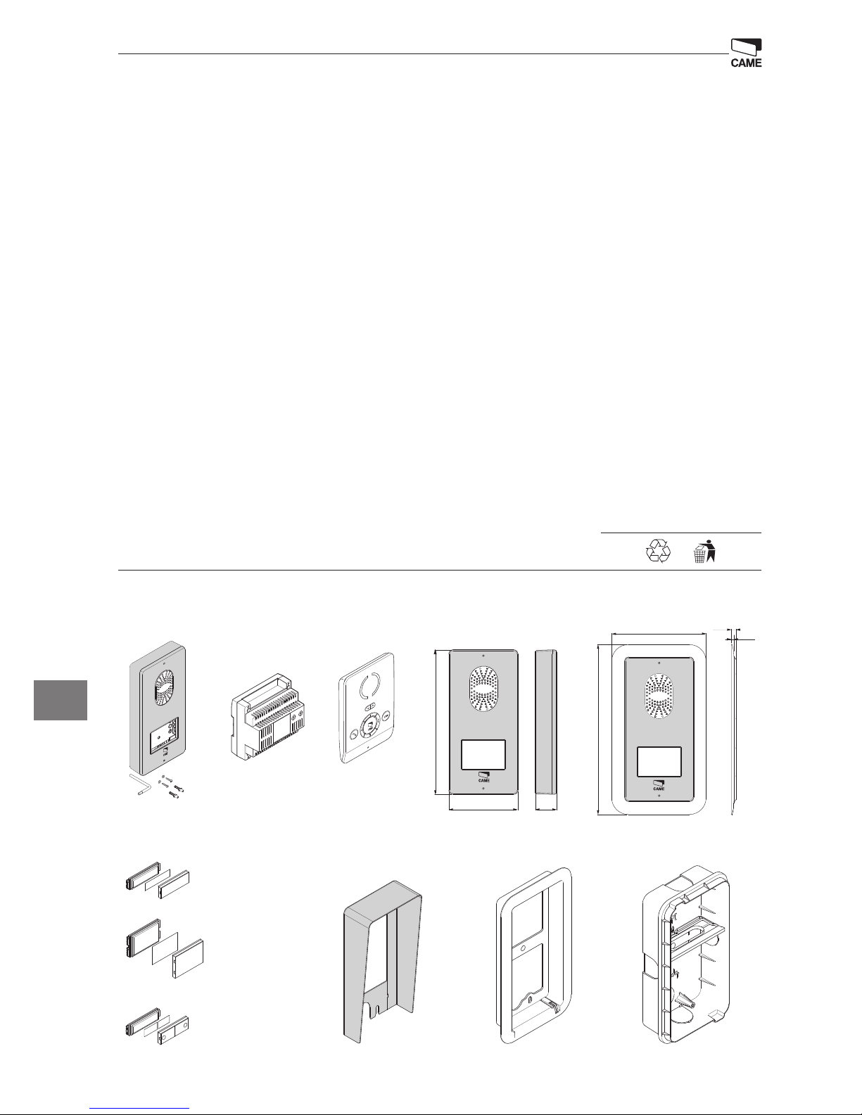
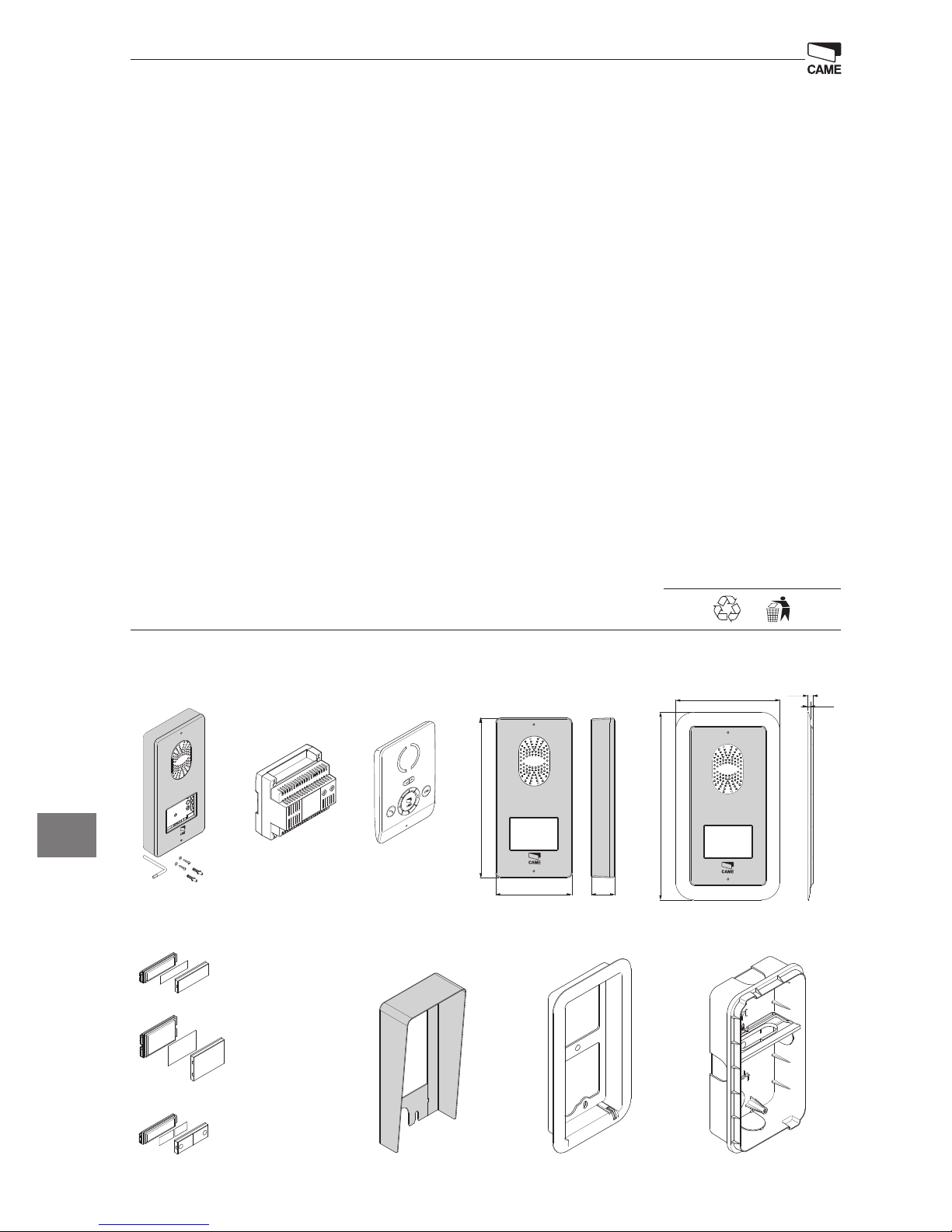
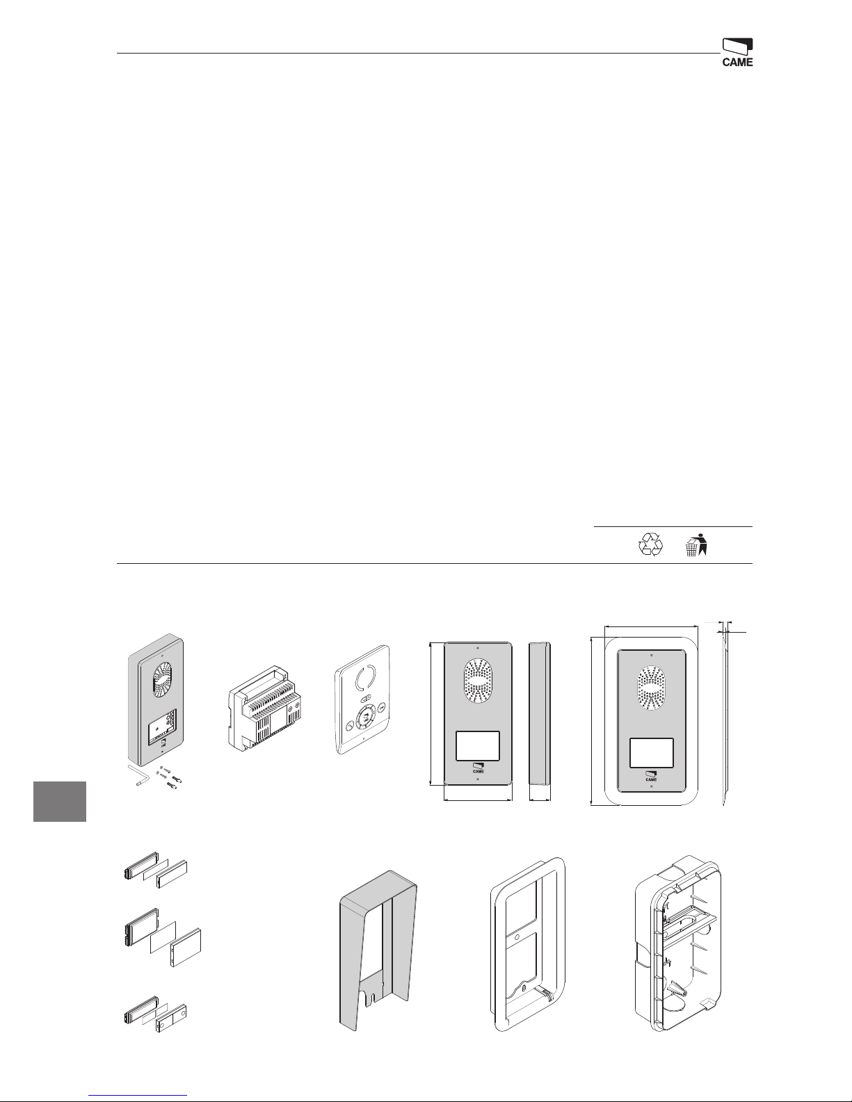
Posto esterno citofonico
Chiave a brugola
2 Tasselli e
2 viti con rosetta
Contenuto dell'imballo
ACCESSORI (da comandare separatamente)
Dimensioni
DPS Pulsante singolo
DPH Pulsante singolo e altezza doppia
DPD Pulsante doppio
LTP Tettuccio da parete LSI Scatola da incasso
LCI Cornice da incasso
Alimentazione
Citofono
Page 3
3
–
B
INT
M1
3/4
1/2
1
2
110
170
31
60
60
83.5
1
2
1
2
1
2
INT
1/2 3/4
INT
1/2 3/4
INT
1/2 3/4
INT
1/2 3/4
4
3
2
1
7
6
5
BIANCA-C
IT
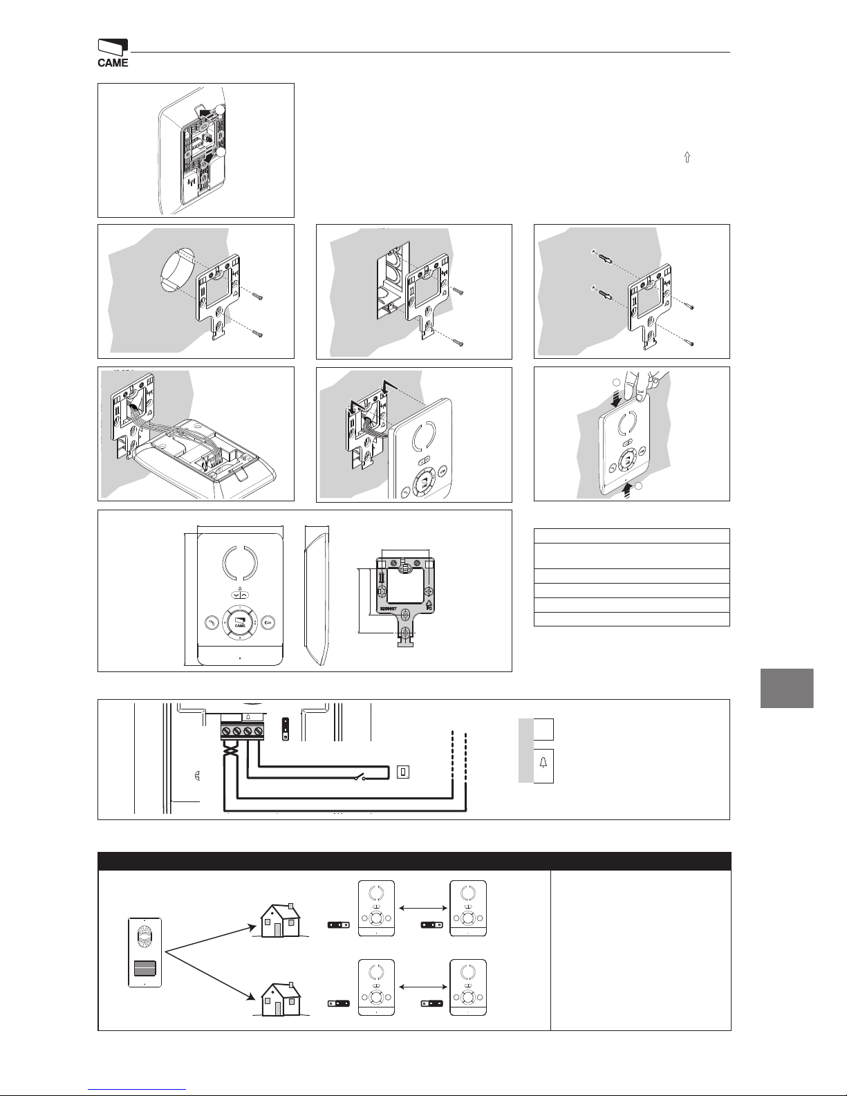
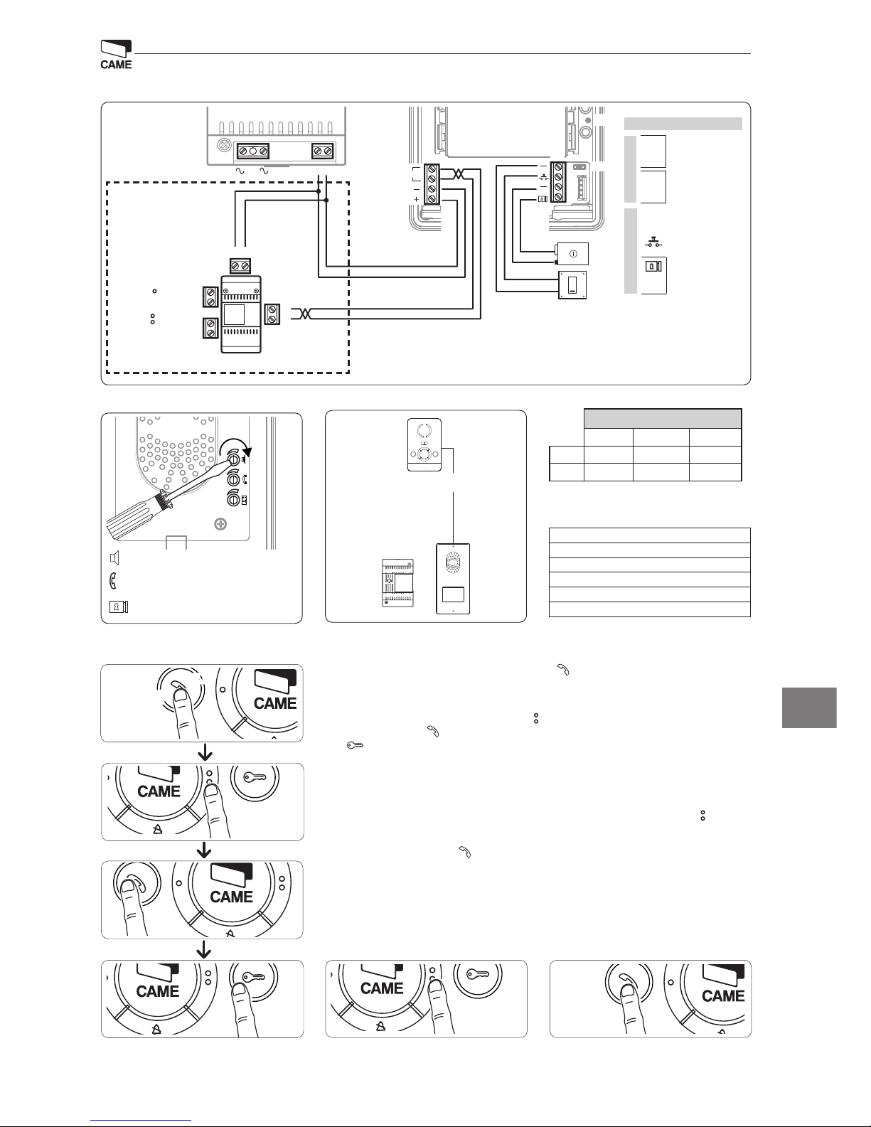
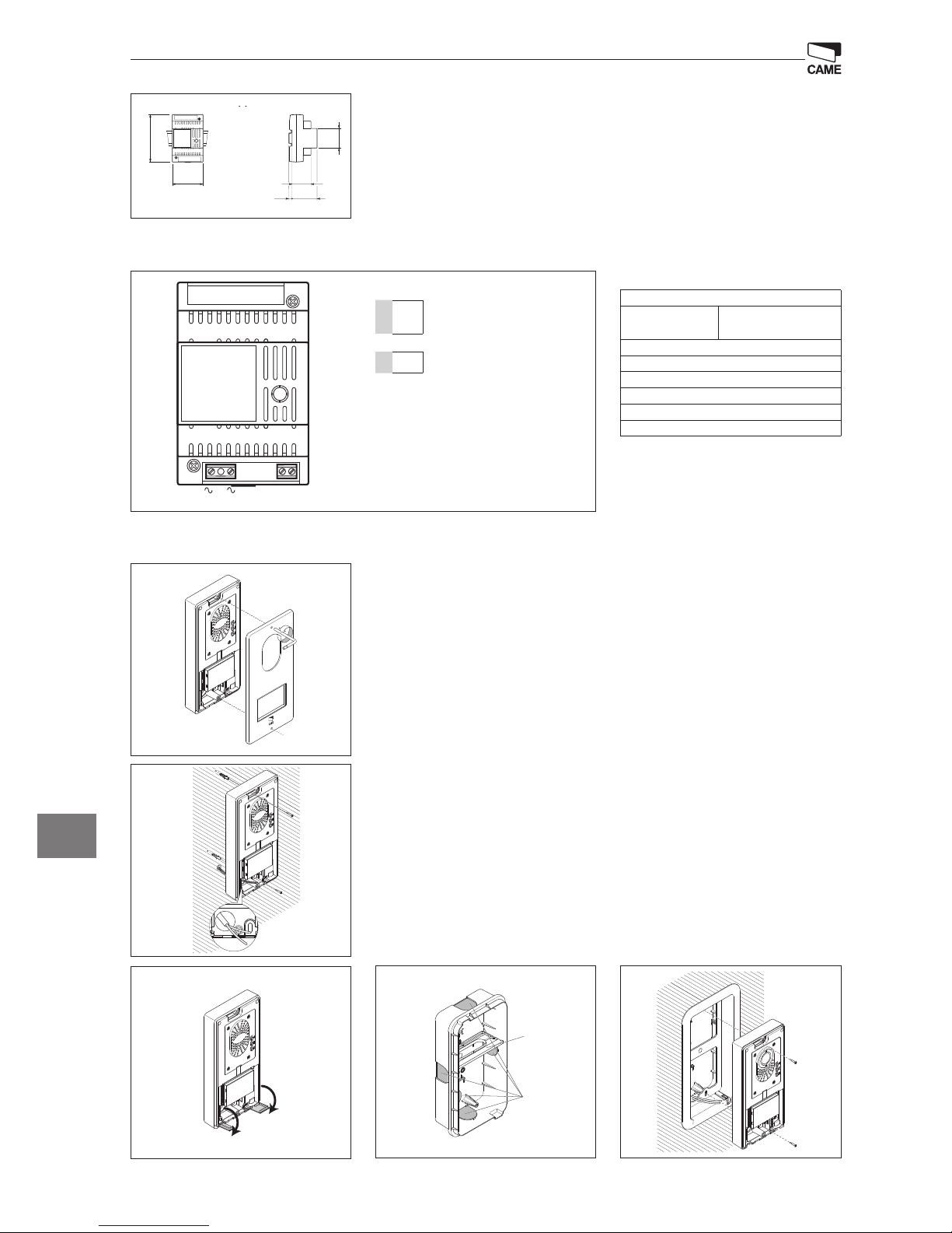
Installazione
Sganciare l’apparecchio dal supporto in plastica,facendolo scorrere su di esso dopo aver premuto il pulsante
plastico (gura 1).
Fissare il supporto in plastica alla scatola d’incasso tonda Ø 60 mm (gura 2) oppure alla scatola rettangolare
503 (gura 3) o alla parete (gura 4), utilizzando le viti in dotazione e rispettando l’indicazione UP .
La scatola deve essere installata a un'altezza adeguata per l'installatore.
Evitare il serraggio eccessivo delle viti.
Eettuati i collegamenti, agganciare il terminale al supporto plastico (gura 5-6).
Per sganciare l’apparecchio dal supporto plastico premere il gancio plastico e sollevare il terminale (gura 7).
Caratteristiche tecniche
Assorbimento: 80 mA max (<1 mA stand-by)
Assorbimento singolo LED (esclusione suone-
ria): 1 mA
Dimensioni: 110x170x31 mm
Temperatura di stoccaggio: -25°C +70 °C
Temperatura d'esercizio: 0 °C +35 °C
Grado di protezione IP: IP 20
Morsettiere
Selezioni
INT
Il jumper INT serve per creare due gruppi
intercom distinti: lasciare il jumper INT nella
posizione “1/2” sui derivati del primo gruppo
e spostare il jumper INT nella posizione “3/4”
sui derivati del secondo gruppo.
M1
B
Ingresso linea BUS (non polarizzato)
–
Chiamata pianerottolo
Page 4
4
43,5
45
7,5
57
70
106
A
A
B
M2M1
+–
1
1
2
4
5
3
VAS/101-CM
PLACO-C
IT
Caratteristiche tecniche
Alimentazione: 230 VAC 50÷60 Hz
Corrente assorbita:
I
max
200 mA
AC
AC
Potenza dissipata: 10 W max
Alimentazione nominale: 18 VDC 1 A-0,5 A 1’/3’
Dimensioni: 4 DIN
Temperatura di stoccaggio: -25 °C + 70 °C
Temperatura d'esercizio: 0 °C +35 °C
Grado di protezione IP: IP 30
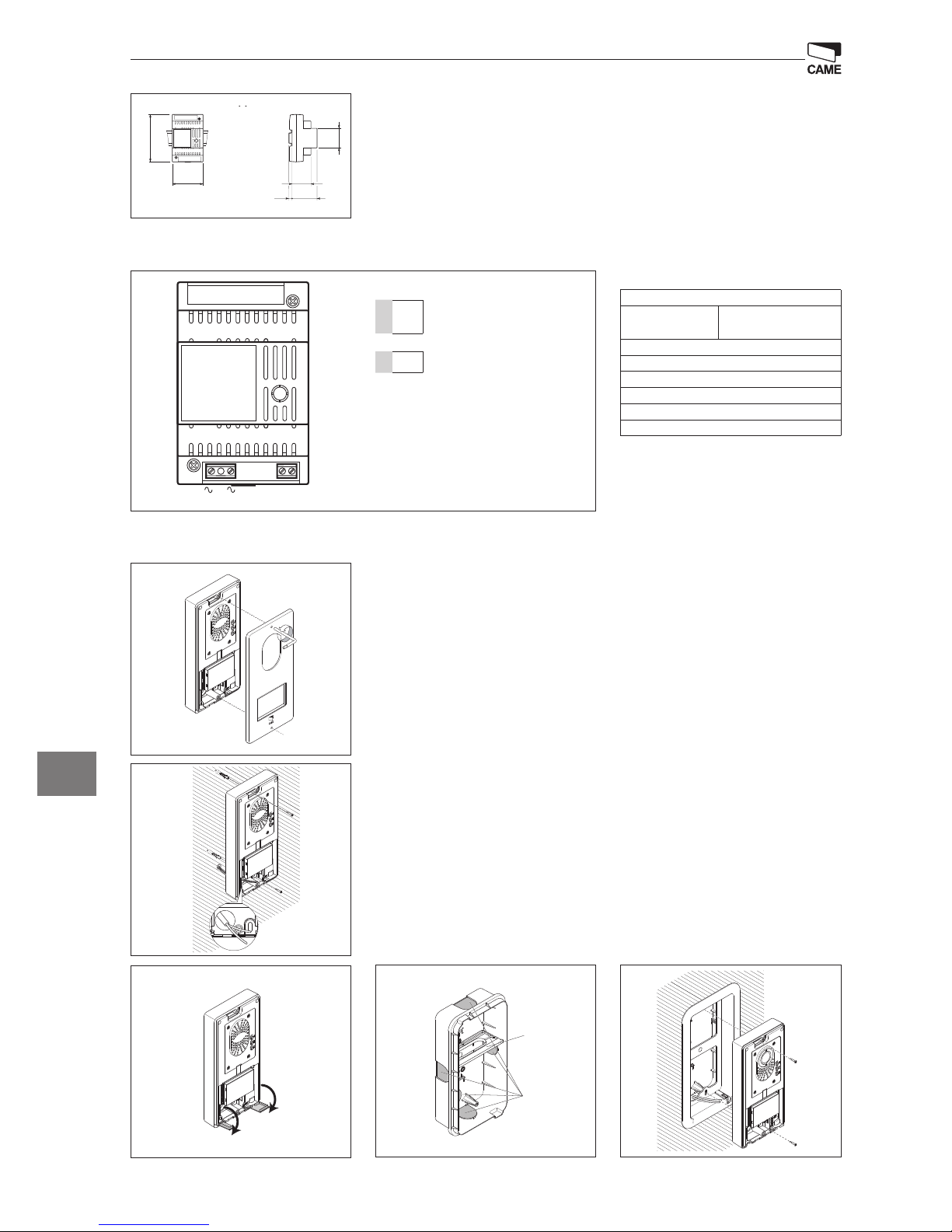
Installazione a parete
Con una chiave a brugola, svitare le viti di bloccaggio e togliere la placca (gura 1). Fissare i tasselli in dotazione
e avvitare il posto esterno (gura 2) all'altezza desiderata. Far passare la guaina con i conduttori d'impianto
come indicato in gura 2.
Estrarre il coprimorsetto in plastica ed eettuare i collegamenti (gura 3). Una volta terminati i collegamenti
reinserire i coprimorsetti. Montare la placca frontale (gura 1).
Installazione a incasso
Sigillare il contenitore da incasso all’altezza desiderata, facendo passare preventivamente la guaina con i conduttori dell’installazione attraverso uno dei punti di rottura (gura 4, punto A).
Nella messa in opera della scatola d’incasso si potranno evitare possibili deformazioni utilizzando l’apposito
distanziale in dotazione (gura 4 punto B).
Con una chiave a brugola, svitare le viti di bloccaggio e togliere la placca del posto esterno (gura 1).
Introdurre i cavi di collegamento nell'apposito foro (gura 2), ssare il posto esterno sulla cornice come indicato in gura 5; estrarre il coprimorsetto in plastica ed eettuare i collegamenti (gura 3).
Una volta terminati i collegamenti reinserire i coprimorsetti.
Montare la placca frontale (gura 1).
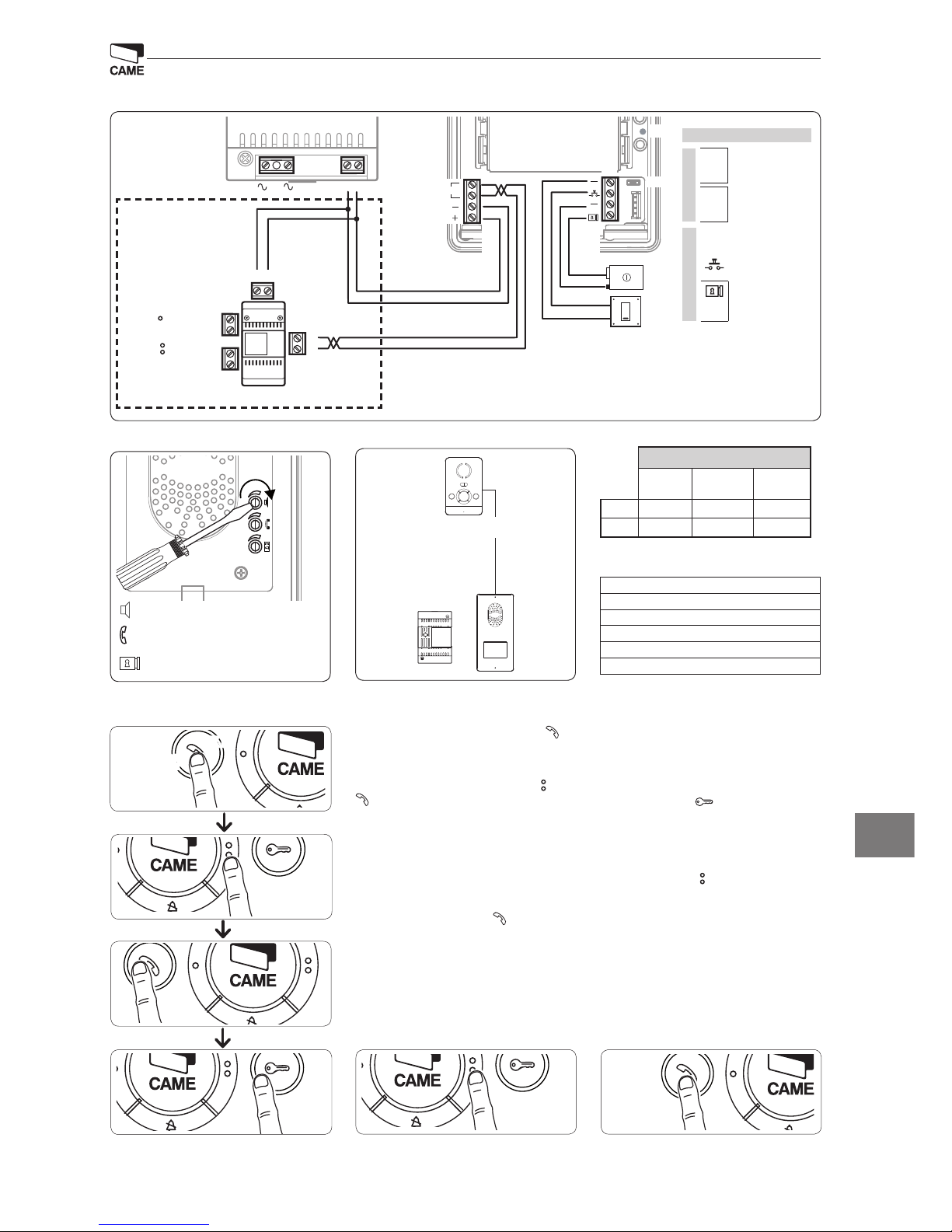
Installazione
L’alimentazione deve SEMPRE essere installata in verticale.
L’apparecchio è installabile su guida DIN (EN 50022) in un apposito quadro elettrico.
Per le dimensioni di ingombro vedere la g. 1.
Prevedere una ventilazione sufficiente nel caso in cui l’alimentazione venga installata in un contenitore.
Morsettiere
M1
~
Rete
~
M2
–
+
Alimentazione 18 VDC (*)
(*) L’apparecchiatura è protetta contro i sovraccarichi e i corto-circuiti.
Page 5
5
M1
BOUT
M2
SW3
PROG
RESET
PROG
M2M1
+–
VLS/300
B
B
NO
C
–
+
NO
C
VAS/101
X 5
beep
La
Lb
VAS/101-CM
a
b
c
d
e f
IT
Caratteristiche tecniche
Alimentazione: 16-18 VDC
Assorbimento: 120 mA (75 mA stand-by)
Dimensioni: 99x207x30 mm
Temperatura di stoccaggio: -25°C +70 °C
Temperatura d'esercizio: -15 °C +50 °C
Grado di protezione IP: IP 54
Ingresso in Programmazione. Premere 5 volte il pulsante entro 5 s. Un breve segnale acustico conferma
l’ingresso in programmazione a.
Programmazione della melodia associata alla chiamata dal posto esterno (1 segnale acustico). per
ascoltare le melodie in sequenza, premere il pulsante b. Per selezionare la melodia ed uscire dalla programmazione premere il tasto c. Per selezionare la melodia e proseguire con la programmazione premere il
tasto d.
Programmazione della melodia associata alla chiamata dal pianerottolo (2 segnali acustici). Per questo
tipo di programmazione b c d procedere come la “Programmazione della melodia associata alla chiamata
dal posto esterno” precedentemente descritta.
Programmazione del numero di squilli di chiamata (3 segnali acustici). Premere il tasto tante volte
quanti sono gli squilli che si è scelto per la chiamata (da 1 a 6 squilli) e. 3 s dall’ultima pressione del tasto verrà
riprodotta la chiamata selezionata per il numero di squilli prescelto. Per selezionare la melodia ed uscire dalla
programmazione premere il tasto f.
Programmazione
y Per la programmazione della chiamata, vedere la documentazione dei posti esterni.
Morsettiera
M1
BOUT
Bus
(non polarizzato)
+
Alimentazione
16-18 VDC
–
M2
– Massa
Pulsante
apriporta (NO)
Elettroserratura
12 V 1 A max
–
Funzioni delle morsettiere
Regolazioni
Distanze
audio altoparlante
audio microfono
elettroserratura 1÷10 s. default 1 s)
Distanze
2x1 mm2UTP/CAT 5 2x2,5mm
2
La ≤250 m ≤250 m –
Lb ≤25 m – ≤60 m
OPZIONE:
Modulo bus
2 uscite ausiliarie
Relè 1
Relè 2
Page 6
6
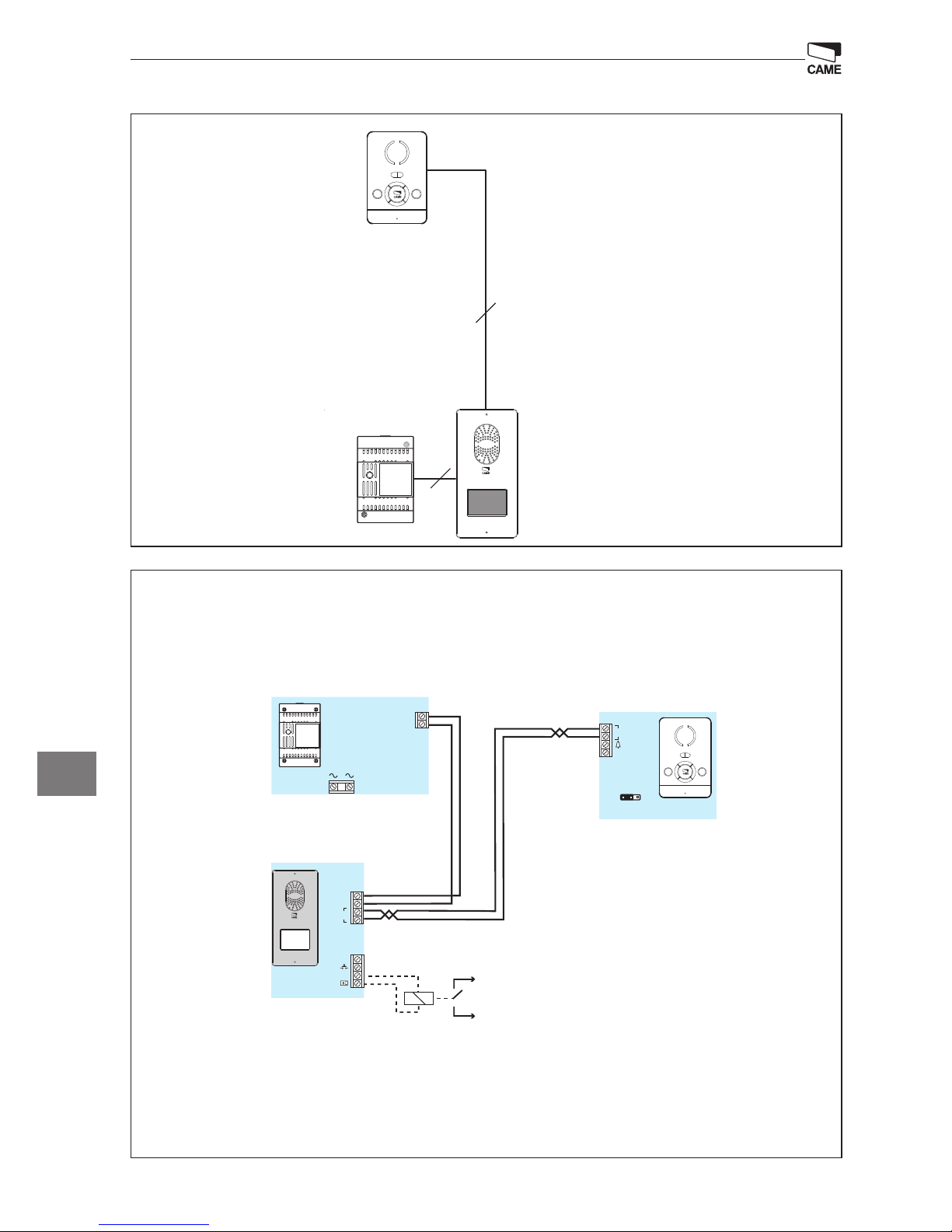
2
INTERCOM 1/2 INTERCOM 3/4
2
VAS/101
2
2
1
1 2
VAS/101
2
+
–
M2
VAS/101
230 V
A
BIANCA-C
M1
B
-
+
BOUT
-
-
-
M1
INT
1/2 3/4
PLACO-C
Automatisme
CAME
Relais
12Vcc
M2
250 m max.
2x1mm
2
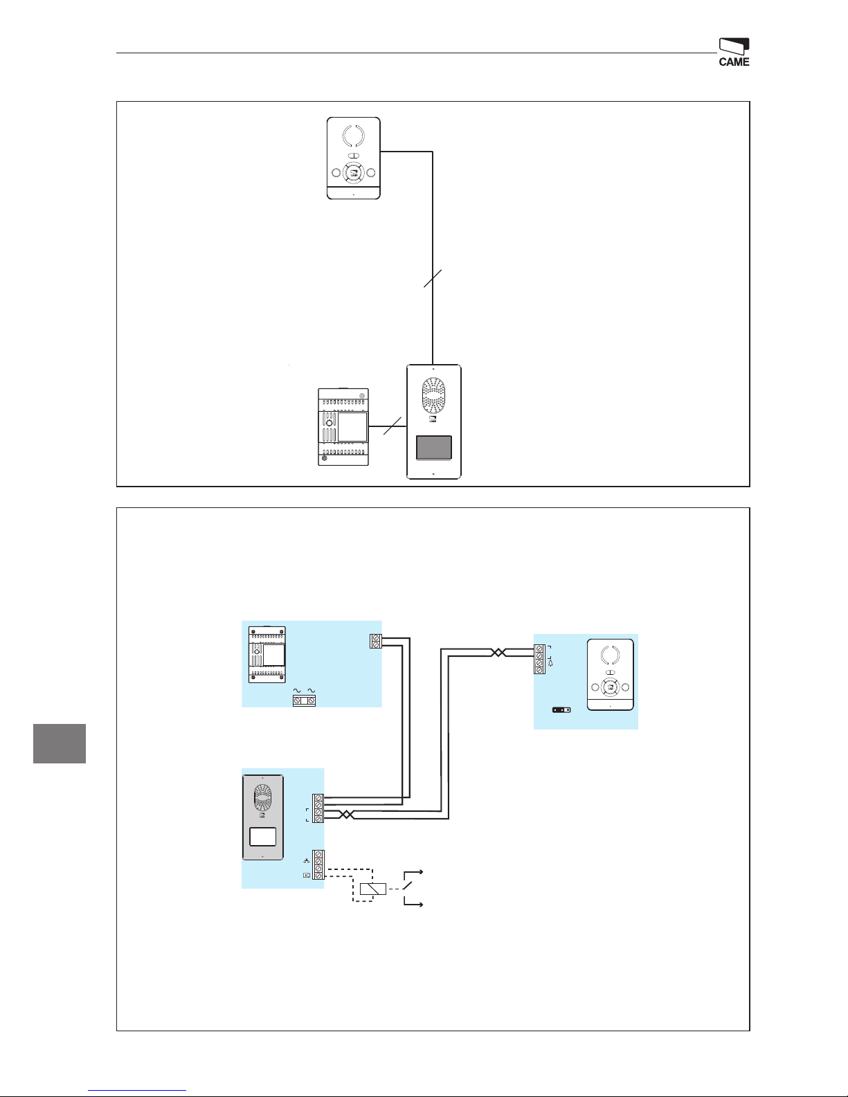
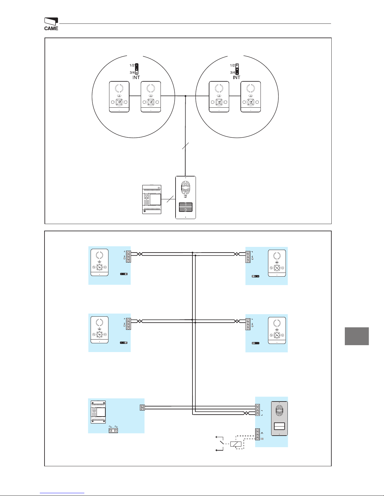
IT
Esempi di collegamento
Page 7
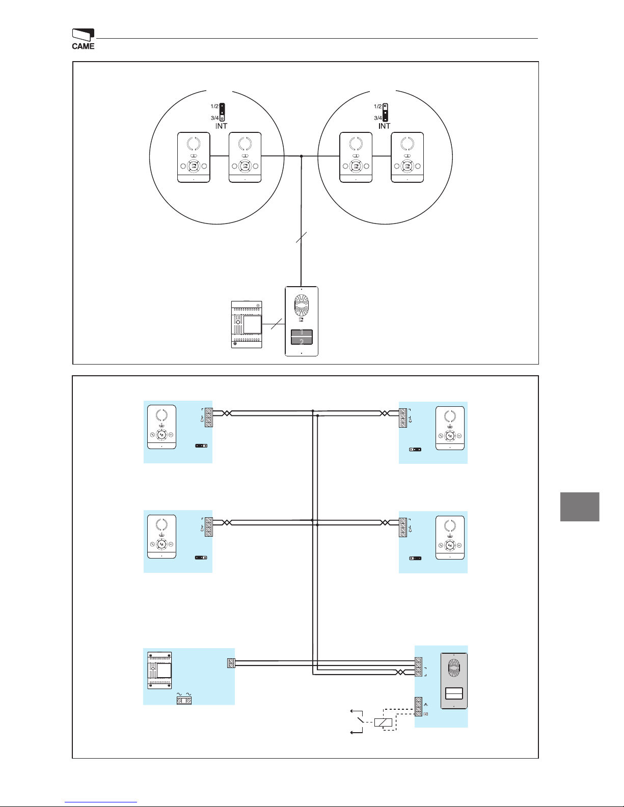
7
2.3
+
BOUT
-
M1
VAS/101
A
+
–
M2
-
-
M1
B
-
2.4
M1
B
-
1.1
M1
B
-
1.2
M1
B
-
INT
1/2 3/4
INT
1/2 3/4
INT
1/2 3/4
INT
1/2 3/4
Automatisme
CAME
Relais
12Vcc
M2
LC/01
PEC/01
PEC/01
PEC/01
PEC/01
2
INTERCOM 1/2 INTERCOM 3/4
VAS/101
2
2
1
1 2
IT
Page 8
2
135
99
30
3.5
6.5
243
207
135
3.5
6.5
243
EN
General warnings
On opening the pack
• Read the instructions carefully before starting installation and proceed as speci ed by the manufacturer;
• After removing the packaging, check the condition of the unit;
• The packaging items (plastic bags, polystyrene foam etc.) must not be handled by children as they may be dangerous;
General installation instructions
• Installation, programming, commissioning and maintenance of the product must only be performed by quali ed technicians who have been properly trained in
compliance with current standards, including health and safety regulations;
• Operate in suffi ciently lit areas that are conducive to health and use tools, utensils and equipment that are in good working order;
• The device must be installed in accordance with the IP degree indicated in the technical features;
• If present, do not obstruct the openings or ventilation/heat dispersing holes;
Wiring the devices
• The electrical system must comply with current standards in the country of installation;
• Before connecting the units, check that the indications on the plate correspond with those of the mains;
• Protect units powered with mains voltage using a single pole mains switch with contact separation of at least 3 mm;
• Wires belonging to cables that are not used must be insulated.
• To prevent accidental contact, tighten the mains connection cables and those for the very low voltage signals separately.
• Weld the joints and the ends of the wires to prevent malfunctions caused by wire oxidation;
Installation completed
• When installation is completed, always check for correct operation of the unit and the system as a whole;
• The installer must check that the information required by the user is present and handed over;
Maintenance
• Before performing any cleaning or maintenance operation, disconnect the power supply to the device. If the units are mains-powered, disconnect the power using
the switch upstream from the units;
• In the case of device failure or malfunction, disconnect it from the power supply and do not tamper with it;
• Should the unit be in need of repair, contact only a technical support centre authorised by the manufacturer and always use spare parts provided by CAME S.p.A.
The units must only be used for the purpose for which they were explicitly designed.
Failure to follow the instructions provided above may compromise the unit’s safety.
The manufacturer declines all liability for any damage as a result of improper, incorrect or unreasonable use.
DISPOSAL
Do not litter the environment with packing material: make sure it is disposed of according to the regulations in force in the country where the product is used.
When the equipment reaches the end of its life cycle, take measures to ensure it is not discarded in the environment.
The equipment must be disposed of in compliance with the regulations in force, recycling its component parts wherever possible.
Components that qualify as recyclable waste feature the relevant symbol and the material’s abbreviation.
Audio entry control
Allen wrench
2 plugs and
2 screws with washer
Packaging contents
ACCESSORIES (to be purchased separately)
Dimensions
DPS Single button
DPH Single button and double height
DPD Double button
LTP Wall roof LSI Recessed box
LCI Recessed frame
Power supplier
Entry phone
Page 9

3
–
B
INT
M1
3/4
1/2
1
2
110
170
31
60
60
83.5
1
2
1
2
1
2
INT
1/2 3/4
INT
1/2 3/4
INT
1/2 3/4
INT
1/2 3/4
4
3
2
1
7
6
5
BIANCA-C
EN
Installation
Remove the unit from the plastic support by sliding it after pressing the plastic button (gure 1).
Fasten the plastic support to the round built-in box of Ø 60 mm (gure 2) or to the rectangular box 503 (gure
3) or to the wall (gure 4), using the provided screws and observing the UP indication .
The box must be tted at a suitable height in relation to the installer.
Avoid excessive tightening of the screws.
Once the connections have been made, attach the terminal to the plastic support (gure 5-6).
To release the unit from the plastic support, press the plastic hook and lift the terminal (gure 7).
Technical features
Absorption: 80 mA max (<1 mA stand-by)
Single LED absorption (ring disabled): 1 mA
Dimensions: 110x170x31 mm
Storage temperature: -25 °C +70 °C
Operating temperature: 0 °C +35 °C
IP degree: IP 20
Terminal boards
Selections
INT
The INT jumper is used to create two separate intercom groups: leave the INT jumper
in position “1/2” on the receivers of the rst
group and move the INT jumper to position
“3/4” on the receivers of the second group.
M1
B
BUS line input (not polarised)
–
Doorbell
Page 10
4
43,5
45
7,5
57
70
106
A
A
B
M2M1
+–
1
1
2
4
5
3
VAS/101-CM
PLACO-C
EN
Technical features
Power supply: 230 VAC 50-60 Hz
Current absorbed
I
max
200 mA
AC
AC
Power dissipated: 10 W max
Rated power supply: 18 VDC 1 A-0.5 A 1’/3’
Dimensions: 4 DIN
Storage temperature: -25 °C + 70 °C
Operating temperature: 0 °C +35 °C
IP degree: IP 30
Wall mounting
With the Allen wrench, unscrew the blocking screws and remove the plate (gure 1). Fix the given plugs and
screw the entry panel (gure 2) at the desired height. Run the sheath with the system conductors as shown
in gure 2.
Extract the plastic terminal cover and wire the connections (gure 3). Once all the connections have been
made, re-insert the terminal covers. Install the front plate (gure 1).
Recessed installation
Install the recessed box at the desired, but in advance, run the sheath with the system conductors through one
of the breaking points (gure 4 point A).
During installation of the recessed box it is possible to avoid any deformation by using the provided spacer
(gure 4 point B).
With the Allen wrench, unscrew the blocking screws and remove the entry panel plate (gure 1).
Introduce the cable connections in the special hole (gure 2) and x the entry panel on the frame as shown in
gure 5; extract the plastic terminal cover and wire the connections (gure 3).
Once all the connections have been made, re-insert the terminal covers.
Install the front plate (gure 1).
Installation
The power supplier must ALWAYS be installed vertically.
The unit can be installed on a DIN guide (EN 50022) in a special electrical panel.
For the overall dimensions, see g. 1.
Provide sufficient ventilation if the power supplier is installed in a container.
Terminal boards
M1
~
Mains
~
M2
–
+
18 VDC power supply (*)
(*) The unit is protected against overloads and
short circuits.
Page 11
5
M1
BOUT
M2
SW3
PROG
RESET
PROG
M2M1
+–
VLS/300
B
B
NO
C
–
+
NO
C
VAS/101
X 5
beep
La
Lb
VAS/101-CM
a
b
c
d
e f
EN
Technical features
Power supply: 16-18 VDC
Absorption: 120 mA max (75 mA stand-by)
Dimensions: 99x207x30 mm
Storage temperature: -25 °C +70 °C
Operating temperature: -15 °C +50 °C
IP degree: IP 54
Accessing programming Press the button ve times within 5 s. A brief acoustic signal will conrm that
programming has been accessed a.
Programming the melody associated with the call from the entry panel (1 acoustic signal). To listen to
the melodies in sequence, press the button b. To select the melody and exit programming, press the button
c. To select the melody and continue with programming, press the button d.
Programming the melody associated with the doorbell (2 acoustic signals). For this type of programming b c d proceed as previously described for “Programming the melody associated to the call from the
entry panel”.
Programming the number of call rings (3 acoustic signals). press the button the number of times equal
to the number of rings selected for the call (from 1 to 6 rings) e. 3 s after the button is pressed the last time,
the call selected for the selected number of rings will be will be reproduced. To save the melody and exit
programming, press the button f.
Programming
y For call programming, see the entry panel documentation.
Terminal board
M1
BOUT
Bus
(not polarised)
+
Power supply
16-18 VDC
–
M2
– Earth
Door release
button (NO)
Electric lock
12 V 1 A max
–
Functions of the terminal boards
Adjustments
Distances
speak audio
microphone audio
electric lock 1-10 s. default 1 s)
Distances
2x1 mm2UTP/CAT 5
2x2.5
mm
2
La ≤250 m ≤250 m –
Lb ≤25 m – ≤60 m
OPTIONAL:
Bus module
2 auxiliary exits
Relay 1
Relay 2
Page 12
6
2
INTERCOM 1/2 INTERCOM 3/4
2
VAS/101
2
2
1
1 2
VAS/101
2
+
–
M2
VAS/101
230 V
A
BIANCA-C
M1
B
-
+
BOUT
-
-
-
M1
INT
1/2 3/4
PLACO-C
Automatisme
CAME
Relais
12Vcc
M2
250 m max.
2x1mm
2
EN
Connection examples
Page 13
7
2.3
+
BOUT
-
M1
VAS/101
A
+
–
M2
-
-
M1
B
-
2.4
M1
B
-
1.1
M1
B
-
1.2
M1
B
-
INT
1/2 3/4
INT
1/2 3/4
INT
1/2 3/4
INT
1/2 3/4
Automatisme
CAME
Relais
12Vcc
M2
LC/01
PEC/01
PEC/01
PEC/01
PEC/01
2
INTERCOM 1/2 INTERCOM 3/4
VAS/101
2
2
1
1 2
EN
Page 14
2
135
99
30
3.5
6.5
243
207
135
3.5
6.5
243
DE
Allgemeine Hinweise
Bei Öff nen der Verpackung
• Vor der Montage die Anleitung aufmerksam durchlesen und alle Arbeiten, wie vom Hersteller angegeben, ausführen;
• Nach dem Auspacken überprüfen, dass das Gerät unversehrt ist;
• Die Bestandteile der Verpackung (Plastiktüten, Polystyrolschaum usw.) müssen außerhalb der Reichweite von Kindern gehalten werden, da sie potentielle Gefahrenquellen darstellen.
Allgemeine Montageanweisungen
• Die Montage, Programmierung, Inbetriebnahme und Wartung des Produkts darf nur von qualifi zierten und entsprechend ausgebildeten Fachpersonal unter Beachtung der geltenden Sicherheitsbestimmungen und Unfallverhütungsmaßnahmen durchgeführt werden;
• In ausreichend beleuchteten und nicht gesundheitsschädigenden Räumen arbeiten und nur Instrumente und Werkzeuge, die in gutem Zustand sind, benutzen;
• Das Gerät muss entsprechend dem in den technischen Daten aufgeführten IP-Schutzgrad montiert werden;
• Wenn vorgesehen, sollten Ö nungen bzw. Lüftungsschlitze zum Auskühlen nicht verdeckt werden;
Elektrischer Anschluss der Geräte
• Die elektrische Anlage muss den im Installationsland geltenden Sicherheitsnormen entsprechen;
• Vor dem Anschluss der Geräte kontrollieren, dass die auf dem Typenschild angegebenen Daten denen des Netzanschlusses entsprechen;
• Die mit Netzstrom gespeisten Geräte mit einem omnipolaren Schutzschalter mit einem Abstand von mindestens 3 mm zwischen den Kontakten, schützen;
• Die nicht verwendeten Steckverbindungen isolieren.
• Um ungewollten Kontakten vorzubeugen, die Netzkabel und die Niederspannungs-Signalleitungen getrennt umbinden.
• Die Anschlussstellen und die Enden der Drähte verschweißen, um Störungen durch Oxidation derselben zu vermeiden;
Montage abgeschlossen
• Nach Abschluss der Montage immer den korrekten Betrieb des Geräts und der gesamten Anlage überprüfen;
• Der Montagefachmann muss überprüfen, dass die benutzerrelevanten Angaben vorhanden sind und dem Benutzer ausgehändigt werden;
Wartung
• vor allen Reinigungs- oder Wartungsmaßnahmen den Netzstecker aus der Dose ziehen; bei mit Netzstrom gespeisten Geräten, die Stromzufuhr durch Ö nen des
davor liegenden Schalters unterbrechen;
• Im Fall einer Störung und/oder des fehlerhaften Betriebs eines Geräts, den Netzstecker aus der Dose ziehen und keine eigenständigen Reparaturen durchführen;
• Für etwaige Reparaturen wenden Sie sich ausschließlich an eine vom Hersteller genehmigte Kundendienststelle. In jedem Fall immer von der CAME S.p.A. gelieferte
Ersatzteile verwenden
Die Geräte dürfen nur für den Zweck, für den sie entwickelt wurden, verwendet werden.
Die Nichtbeachtung der oben aufgeführten Vorschriften kann die Sicherheit des Geräts beeinträchtigen.
Der Hersteller haftet nicht für Schäden, die durch den unsachgemäßen, falschen oder unvernünftigen Gebrauch verursacht werden.
Entsorgung
Vergewissern Sie sich, dass das Verpackungsmaterial gemäß den Vorschriften des Bestimmungslandes ordnungsgemäß und umweltgerecht entsorgt wird.
Das nicht mehr benutzbare Gerät muss umweltgerecht entsorgt werden und darf nicht in die Umwelt gelangen.
Das Gerät muss gemäß den geltenden Vorschriften entsorgt werden, dabei muss das Recycling der Bestandteile des Geräts bevorzugt werden.
Die wiederverwertbaren Bestandteile des Geräts, sind mit einem Symbol und dem Material-Kürzel gekennzeichnet.
Außenstation Sprechanlage
Inbusschlüssel
2 Dübel und
2 Schrauben mit Unterlegscheibe
Inhalt der Verpackung
ZUSATZTEILE (müssen getrennt erworben werden)
Maße
DPS Einfachtaster
DPH Einfachtaster e doppelte Höhe
DPD Doppeltaste
(Ltp) Überdachung für Wandmontage LSI Unterputzschachtel
LCI Unterputzrahmen
Netzgerät
Sprechanlage
Page 15

3
–
B
INT
M1
3/4
1/2
1
2
110
170
31
60
60
83.5
1
2
1
2
1
2
INT
1/2 3/4
INT
1/2 3/4
INT
1/2 3/4
INT
1/2 3/4
4
3
2
1
7
6
5
BIANCA-C
DE
Montage
Das Gerät aus der Kunststohalterung aushängen, dabei nach Druck auf die Kunststotaste auf der Halterung
verschieben (Abbildung 1).
Die Kunststohalterung an der Unterputzdose Ø 60 mm (Abbildung 2) bzw. an der Unterputzschachtel 503
(Abbildung 3) oder an der Wand (Abbildung 4) befestigen, hier für die beiliegenden Schrauben verwenden
und die Angabe UP beachten. Die Schachtel muss in für den Montagefachmann geeigneter Höhe montiert
werden. Die Schrauben nicht zu stark anziehen. Nach Vornahme der Anschlüsse, das Videoterminal in die
Kunststohalterung einhängen (Abbildung 5-6). Um das Gerät aus der Kunststohalterung auszurasten, den
Kunststohaken drücken und das Terminal anheben (Abbildung 7).
Technische Daten
Stromaufnahme: 80 mA max (<1 mA stand-by)
Stromaufnahme pro LED (Läutwerkabschal-
tung): 1 mA
Maße: 110x170x31 mm
Lagertemperatur: -25°C+70 °C
Betriebstemperatur: 0 °C+35 °C
Schutzart: IP 20
Klemmleisten
Auswahl
INT
Mit dem INT-Jumper werden zwei verschiedene Intercom-Gruppen angelegt: INT-Jumper für die Innensprechstellen der ersten
Gruppe in der Stellung "1/2" lassen und für
die Innensprechstellen der zweiten Gruppe
in die Stellung "3/4" verschieben.
M1
B
Eingang BUS-Leitung (ungepolt)
–
Anruf vom Treppenhaus
Page 16

4
43,5
45
7,5
57
70
106
A
A
B
M2M1
+–
1
1
2
4
5
3
VAS/101-CM
PLACO-C
DE
Technische Daten
Betriebsspannung 230 VAC 50÷60 Hz
Stromaufnahme:
I
max
200 mA
AC
AC
Verlustleistung: max. 10 W
Nennspannung: 18 VDC 1 A-0,5 A 1’/3’
Maße: 4 DIN
Lagertemperatur: -25 °C+ 70 °C
Betriebstemperatur: 0 °C+35 °C
Schutzart IP 54: IP 30
Wandmontage
Mit dem Inbusschlüssel die Befestigungsschrauben lösen und die Blende abnehmen (Abbildung 1). Die mitgelieferten Dübel einstecken und die Außenstation (Abbildung 2) in gewünschter Höhe anschrauben (Abbildung 3). Wie in Abbildung 2 dargestellt, den Kabelschlauch mit den Anlagenleitern hindurchführen.
Die Kunststo-Klemmenabdeckung entfernen und die Anschlüsse vornehmen (Abbildung 3). Nach Vornahme
der Anschlüsse, die Klemmenabdeckungen wieder einstecken. Frontblende montieren (Abbildung 1).
Unterputz-Montage
Die Unterputzschachtel in gewünschter Höhe einbauen, zuvor den Kabelschlauch mit den Anlageleitern
durch eines der vorgestanzten Löcher führen (Abbildung 4, Punkt A).
Beim Einsetzen der Unterputzschachtel können durch Verwendung des beiliegenden Abstandshalters Verformungen vermieden werden (Abbildung 4 Punkt B).
Mit dem Inbusschlüssel die Befestigungsschrauben lösen und die Blende der Außenstation abnehmen (Abbildung 1).
Die Anschlusskabel durch die entsprechende Aussparung ziehen (Abbildung 2) und die Außenstation, wie in
Abbildung 5 dargestellt, auf dem Rahmen befestigen; Die Kunststo-Klemmenabdeckung entfernen und die
Anschlüsse vornehmen (Abbildung 3).
Nach Vornahme der Anschlüsse, die Klemmenabdeckungen wieder einstecken.
Frontblende montieren (Abbildung 1).
Montage
Das Netzgerät muss IMMER senkrecht montiert werden.
Das Gerät kann auf einer DIN-Schiene (EN 50022) in einem dafür vorgesehenen Schaltschrank montiert werden. Für die Abmessungen siehe die Abbildung 1.
Falls das Netzgerät in einem Gehäuse montiert wird, für ausreichende Belüftung sorgen.
Klemmleisten
M1
~
Netz
~
M2
–
+
Betriebsspannung 18 VDC (*)
(*) Das Gerät ist vor Überlastungen und Kurzschlüssen elektronisch geschützt.
Page 17

5
M1
BOUT
M2
SW3
PROG
RESET
PROG
M2M1
+–
VLS/300
B
B
NO
C
–
+
NO
C
VAS/101
X 5
beep
La
Lb
VAS/101-CM
a
b
c
d
e f
DE
Technische Daten
Betriebsspannung 16-18 VDC
Stromaufnahme: 120 mA (75 mA stand-by)
Maße: 99x207x30 mm
Lagertemperatur: -25°C+70 °C
Betriebstemperatur: -15 °C+50 °C
Schutzart IP 54: IP 54
Zugang zur Programmierung. Innerhalb von 5 Sek. 5 Mal den Taster drücken Ein kurzer Signalton bestä-
tigt den Einstieg in die Programmierung a.
Programmierung der dem Anruf durch die Außenstation zugeordneten Melodie (1 Signalton). um die
Melodien nacheinander anzuhören, die Taste b . Um die Melodie auszuwählen und aus der Programmierung auszusteigen die Taste c drücken. Um die Melodie auszuwählen und die Programmierung
fortzuführen, die Taste d drücken.
Programmierung der einem Anruf vom Treppenhaus zugeordneten Melodie (2 Signaltöne). Für diese
Programmierungsweise b c d wie in der zuvor beschriebenen "Programmierung der dem Anruf durch die
Außenstation zugeordneten Melodie" vorgehen.
Programmierung der Anzahl der Ruftöne (3 Signaltöne). Die Taste so oft drücken, wie die für den Anruf
gewünschten Ruftöne (1 bis 6 Ruftöne)e. 3 Sek. nach dem letzten Tastendruck wird der gewählte Anruf mit
der Anzahl der festgelegten Ruftöne wiederholt. Um die Melodie einzuspeichern und aus der Programmie-
rung auszusteigen die Taste f drücken.
Programmierung
y Für die Rufprogrammierung, siehe die Unterlagen der Außenstationen.
Klemmleiste
M1
BOUT
Bus
(ungepolt)
+
B et ri e bs sp a nnung
16-18 VDC
–
M2
– Masse
Taster
Türöner (NO)
Elektroschloss
12 V max. 1 A
–
Belegung der Klemmleisten
Einstellungen
Abstände
Audio Lautsprecher
Audio Mikrofon
Elektroschloss 1÷10 Sek. Default 1 Sek.)
Abstände
2x1 mm2UTP/CAT 5 2x2,5mm
2
La ≤250 m ≤250 m –
Lb ≤25 m – ≤60 m
OPTIONELL:
Bus-Modul
2 Neben-Outputs
Relais 1
Relais 2
Page 18

6
2
INTERCOM 1/2 INTERCOM 3/4
2
VAS/101
2
2
1
1 2
VAS/101
2
+
–
M2
VAS/101
230 V
A
BIANCA-C
M1
B
-
+
BOUT
-
-
-
M1
INT
1/2 3/4
PLACO-C
Automatisme
CAME
Relais
12Vcc
M2
250 m max.
2x1mm
2
DE
Anschlussbeispiele
Page 19

7
2.3
+
BOUT
-
M1
VAS/101
A
+
–
M2
-
-
M1
B
-
2.4
M1
B
-
1.1
M1
B
-
1.2
M1
B
-
INT
1/2 3/4
INT
1/2 3/4
INT
1/2 3/4
INT
1/2 3/4
Automatisme
CAME
Relais
12Vcc
M2
LC/01
PEC/01
PEC/01
PEC/01
PEC/01
2
INTERCOM 1/2 INTERCOM 3/4
VAS/101
2
2
1
1 2
DE
Page 20

2
135
99
30
3.5
6.5
243
207
135
3.5
6.5
243
FR
Avertissements généraux
Au moment de l’ouverture de l’emballage
• Lire attentivement les instructions avant de commencer l’installation et e ectuer les opérations comme spéci é par le est bien en bon état ;
• Après l’avoir déballé, véri er que l’appareil est bien en bon état ;
• Ne pas laisser les éléments d’emballage (sachets en plastique, polystyrène expansé, etc.) à la portée des enfants car ils constituent une source potentielle de danger ;
Prescriptions générales pour l’installation
• L’installation, la programmation, la mise en service et l’entretien du produit ne doivent être e ectués que par du personnel technique quali é et spécialisé, en respectant les normes en vigueur, y compris celles en matière de prévention des accidents ;
• Travailler dans des lieux salubres et suffi samment éclairés et n’utiliser que des outils et des instruments en bon état ;
• Le dispositif doit être installé conformément au degré IP indiqué dans les caractéristiques techniques ;
• Ne pas obstruer les éventuelles ouvertures/ori ces de ventilation ou d’élimination de la chaleur;
Branchement électrique des dispositifs
• L’installation électrique devra être réalisée conformément aux normes en vigueur dans le pays d’installation ;
• Avant de raccorder les appareils, contrôler que les indications reportées sur la plaque correspondent à celles du réseau électrique ;
• Protéger les appareils sous tension de réseau par le biais d’un interrupteur de réseau omnipolaire avec séparation des contacts d’au moins 3 mm ;
• Les conducteurs non utilisés doivent être isolés ;
• Pour éviter les contacts accidentels, serrer séparément les câbles de branchement au réseau et ceux des signaux en très basse tension ;
• Souder les jonctions et la partie terminale des ls a n d’éviter que leur oxydation ne crée des dysfonctionnements ;
Fin de l’installation
• À la n de l’installation, toujours contrôler le bon fonctionnement de l’appareil et de toute l’installation ;
• L’installateur doit s’assurer que les informations utiles à l’utilisateur sont bien présentes et qu’elles lui ont bien été fournies ;
Entretien
• Avant d’e ectuer toute opération de nettoyage ou d’entretien, couper l’alimentation électrique du dispositif ; en cas d’appareils sous tension de réseau, couper l’alimentation en ouvrant l’interrupteur situé en amont de ces derniers ;
• En cas de panne et/ou de mauvais fonctionnement d’un dispositif, le débrancher du réseau électrique, sans tenter aucune réparation ;
• Pour toute réparation, adressez-vous uniquement à un centre d’assistance technique agréé par le fabricant et dans tous les cas utilisez toujours des pièces de rechange fournies par CAME s.p.a ;
Les appareils devront être destinés uniquement à l’usage pour lequel ils ont expressément été conçus ;
Le non-respect des prescriptions susmentionnées pourrait compromettre la sécurité de l’appareil ;
Le fabricant ne pourra dans tous les cas être tenu responsable des dommages dérivant d’une utilisation incorrecte ou erronée.
ÉLIMINATION
S’assurer que le matériel d’emballage n’est pas abandonné dans la nature et qu’il est éliminé conformément aux normes en vigueur dans le pays d’utilisation du produit.
À la n du cycle de vie de l’appareil, faire en sorte qu’il ne soit pas abandonné dans la nature.
L’appareil doit être éliminé conformément aux normes en vigueur et en privilégiant le recyclage de ses pièces.
Le symbole et le sigle du matériau sont indiqués sur les pièces pour lesquelles le recyclage est prévu.
Poste extérieur d’interphonie
Clé à six pans
2 Chevilles et
2 vis avec rondelle
Contenu de l’emballage
ACCESSOIRES (à commander séparément)
Dimensions
DPS Bouton simple
DPH Bouton simple et hauteur double
DPD Bouton double
LTP Visière de protection murale LSI Boîtier à encastrer
LCI Cadre pour encastrement
Alimentation
Combiné
Page 21

3
–
B
INT
M1
3/4
1/2
1
2
110
170
31
60
60
83.5
1
2
1
2
1
2
INT
1/2 3/4
INT
1/2 3/4
INT
1/2 3/4
INT
1/2 3/4
FR
Installation
Retirer l’appareil du support en plastique, en le faisant glisser sur lui-même après avoir appuyé sur la touche
plastique (gure 1).
Fixer le support en plastique au boîtier d’encastrement rond Ø 60 mm (gure 2) ou au boîtier rectangulaire 503
(gure 3) ou sur le mur (gure 4), en utilisant les vis fournies et en respectant l’indication UP .
Le boîtier doit être installé à une hauteur adéquate pour l’utilisateur.
Éviter de serrer excessivement les vis.
Une fois les raccordements eectués, xer le terminal au support en plastique (gures 5-6).
Pour retirer l’appareil du support en plastique, appuyer sur le clip en plastique et soulever le terminal (gure 7).
Caractéristiques techniques
Absorption : 80 mA max (<1 mA stand-by)
Absorption individuelle LED (Désactivation
sonnerie) : 1 mA
Dimensions : 110x170x31 mm
Température de stockage : -25°C +70 °C
Température de fonctionnement : 0 °C +35 °C
Degré IP : IP 20
Borniers
Sélections
INT
Le cavalier INT sert à créer deux groupes intercom distincts : laisser le cavalier INT sur
la position “1/2” sur les dérivés du premier
groupe et déplacer le cavalier INT sur la position “3/4” sur les dérivés du deuxième groupe.
M1
B
Entrée ligne BUS (non polarisé)
–
Appel depuis le palier
4
3
2
1
7
6
5
BIANCA-C
Page 22

4
43,5
45
7,5
57
70
106
A
A
B
M2M1
+–
FR
Caractéristiques techniques
Alimentation : 230 VAC 50÷60 Hz
Courant absorbé:
I
max
=200 mA
AC
AC
Puissance dissipée : 10 W max
Alimentation nominale : 18 VDC 1 A-0,5 A 1’/3’
Dimensions : 4 DIN
Température de stockage : -25 °C + 70 °C
Température de fonctionnement : 0 °C +35 °C
Degré IP : IP 30
Installation murale
À l’aide de la clé à six pans, dévisser les vis de blocage et retirer la plaque (gure 1). Fixer les chevilles fournies
et visser le poste extérieur (gure 2) à la hauteur souhaitée. Faire passer la gaine avec les conducteurs de l’installation comme indiqué à la gure 2.
Extraire le cache-borne en plastique et eectuer les branchements (gure 3). Une fois les branchement terminés, réinsérer les cache-bornes. Monter la plaque frontale (gure 1).
Installation à encastrer
Sceller le boîtier à encastrer à la hauteur souhaitée en faisant préalablement passer la gaine avec les conducteurs de l’installation à travers un des points de rupture (gure 4 point A).
Lors de la mise en place du boîtier à encastrer, éviter toute déformation en utilisant la cale fournie et prévue à
cet eet (gure 4 point B).
À l’aide de la clé à six pans, dévisser les vis de blocage et retirer la plaque du poste extérieur (gure 1).
Introduire les câbles de branchement dans le trou prévu à cet eet (gure 2), xer le poste extérieur sur le cadre comme indiqué à la gure 5 ; extraire le cache-borne en plastique et eectuer les branchements (gure 3).
Une fois les branchements terminés, réinsérer les cache-bornes.
Monter la plaque frontale (gure 1).
Installation
Le bloc d’alimentation doit TOUJOURS être installé à la verticale.
L’appareil peut être installé sur rail DIN (EN 50022) dans un tableau électrique prévu à cet eet.
Pour les dimensions hors tout, voir la g. 1.
Prévoir une ventilation suffisante en cas de bloc d’alimentation installé dans un boîtier.
Borniers
M1
~
Secteur
~
M2
–
+
Alimentation 18 VDC (*)
(*) L’appareil est protégé électroniquement contre les surcharges et les courts-circuits.
1
1
2
4
5
3
VAS/101-CM
PLACO-C
Page 23

5
M1
BOUT
M2
SW3
PROG
RESET
PROG
M2M1
+–
VLS/300
B
B
NO
C
–
+
NO
C
VAS/101
X 5
beep
FR
Caractéristiques techniques
Alimentation: 16-18 VDC
Absorption: 120 mA (75 mA stand-by)
Dimensions: 99x207x30 mm
Température de stockage: -25°C +70 °C
Température de fonctionnement: -15 °C +50 °C
Degré IP: IP 54
Entrée en Programmation. Appuyer 5 fois sur la touche dans les 5 s. Un bref signal sonore conrme
l’entrée dans la programmation a.
Programmation de la mélodie associée à l’appel provenant du poste extérieur (1 signal sonore). Pour
écouter les mélodies en séquence, appuyer sur la touche b. Pour sélectionner la mélodie et quitter la programmation, appuyer sur la touche c. Pour sélectionner la mélodie et continuer la programmation, appuyer sur la touche d.
Programmation de la mélodie associée à l’appel provenant du palier (2 signaux sonores). Pour ce type
de programmation b c d procéder comme pour la “Programmation de la mélodie associée à l’appel prove-
nant du poste extérieur” décrite précédemment.
Programmation du nombre de sonneries d’appel (3 signaux sonores). Appuyer sur la touche autant de
fois que le nombre de sonneries que l’on a choisi pour l’appel (de 1 à 6 sonneries) e. 3 s après le dernier enfoncement de la touche, l’appel sélectionné pour le nombre de sonneries choisi sera eectué. Pour sauvegarder
la mélodie et quitter complètement la programmation, appuyer sur la touche f.
Programmation
y Pour la programmation de l’appel, voir la documentation des postes extérieurs.
Bornier
M1
BOUT
Bus
(non polarisé)
+
Alimentation
16-18 VDC
–
M2
– Masse
Bouton
ouvre-porte (NO)
Gâche électrique
12 V 1 A max
–
Fonctions des bornes
Réglages
Distances
audio haut-parleur
audio micro
gâche électrique 1÷10 s. défaut 1 s)
Distances
2x1 mm2UTP/CAT 5 2x2,5mm
2
La ≤250 m ≤250 m –
Lb ≤25 m – ≤60 m
OPTION :
Module bus
2 sorties auxiliaires
Relais 1
Relais 2
La
Lb
VAS/101-CM
a
b
c
d
e f
Page 24

6
2
INTERCOM 1/2 INTERCOM 3/4
2
VAS/101
2
2
1
1 2
VAS/101
2
+
–
M2
VAS/101
230 V
A
BIANCA-C
M1
B
-
+
BOUT
-
-
-
M1
INT
1/2 3/4
PLACO-C
Automatisme
CAME
Relais
12Vcc
M2
250 m max.
2x1mm
2
FR
Exemples de raccordement
Page 25

7
2.3
+
BOUT
-
M1
VAS/101
A
+
–
M2
-
-
M1
B
-
2.4
M1
B
-
1.1
M1
B
-
1.2
M1
B
-
INT
1/2 3/4
INT
1/2 3/4
INT
1/2 3/4
INT
1/2 3/4
Automatisme
CAME
Relais
12Vcc
M2
LC/01
PEC/01
PEC/01
PEC/01
PEC/01
2
INTERCOM 1/2 INTERCOM 3/4
VAS/101
2
2
1
1 2
FR
Page 26

2
135
99
30
3.5
6.5
243
207
135
3.5
6.5
243
ES
Advertencias generales
Cuando se abre el embalaje
• Lea atentamente las instrucciones antes de comenzar la instalación, y realice las intervenciones tal y como especi ca el fabricante;
• Después de haber quitado el embalaje cerciorarse que el equipo esté íntegro;
• Los elementos del embalaje (bolsas de plástico, poliestireno expandido, etc.) no deben dejarse al alcance de los niños, ya que son potenciales fuentes de peligro;
Indicaciones generales para la instalación
• La instalación, la programación, la puesta en servicio y el mantenimiento del producto deben ser efectuadossolamente por personal técnico cuali cado que cuente
con la formación pertinente, cumpliendo las normativas vigentes, incluidas las normas de prevención de accidentes;
• Trabaje en entornos su cientemente iluminados e idóneos para la salud, y utilice herramientas, utensilios y equipamiento en buen estado;
• El dispositivo debe instalarse de manera conforme al grado IP indicado en las características técnicas;
• No obstruir las aberturas u ori cios de ventilación o para la eliminación de calor;
Conexión eléctrica de los dispositivos
• La instalación eléctrica deberá realizarse conforme a las normativas vigentes en el país de instalación;
• Antes de conectar los aparatos, controlar que las indicaciones presentes en la placa correspondan con las de la red eléctrica;
• Proteger los aparatos alimentados con tensión de red mediante un interruptor de red omnipolar y con una separación de los contactos de 3 mm como mínimo;
• Es preciso aislar los conductores de los cableados no utilizados.
• Para evitar los contactos accidentales, apretar por separado los cables de conexión a la red y los de las señales de muy baja tensión.
• Suelde las junturas y la parte terminal de los hilos para evitar funcionamientos defectuosos causados por su oxidación;
Instalación terminada
• Al nal del proceso de instalación, compruebe el correcto funcionamiento del equipo y de la instalación en su conjunto;
• El instalador debe controlar que las informaciones útiles al usuario estén presentes y sean entregadas;
Mantenimiento
• Antes de efectuar cualquier operación de limpieza o mantenimiento, corte la alimentación del dispositivo; en caso de aparatos alimentados con tensión de red, desconecte la alimentación abriendo el interruptor que se encuentra en entrada de los mismos;
• En caso de avería y/o funcionamiento defectuoso de un dispositivo, desconéctelo de la alimentación y no lo manipule;
• Si es necesario efectuar reparaciones, acuda únicamente a un centro de asistencia técnica autorizado por el fabricante, y en cualquier caso utilice siempre los recambios suministrados CAME S.p.A.
Los aparatos deberán destinarse únicamente al uso para el que han sido expresamente diseñados.
El incumplimiento de las instrucciones podría poner en peligro la seguridad del aparato.
En cualquier caso, el fabricante no se asumirá ninguna responsabilidad por posibles daños derivados de usos impropios, incorrectos o irrazonables.
ELIMINACIÓN
Comprobar que no se tire al medioambienteel material de embalaje, sino que sea eliminado conforme a las normas vigentes en el país donde se utilice el producto.
Al nal del ciclo de vida del aparato evítese que éste sea tirado al medioambiente.
La eliminación del aparato debe efectuarse conformea las normas vigentes y privilegiando el reciclaje de sus partes componentes.
En los componentes, para los cuales está prevista la eliminación con reciclaje, se indican el símbolo y la sigla del material.
Placa externa citofónica
Lave Allen
2 Tacos y
2 tornillos con arandela
Contenido del embalaje
ACCESORIOS (comprar aparte)
Dimensiones
DPS Botón simple
DPH Botón simple e de doble altura
DPD Botón doble
LTP Visera de super cie LSI Caja de empotrar
LCI Marco empotrable
Alimentador
Citófono
Page 27

3
–
B
INT
M1
3/4
1/2
1
2
110
170
31
60
60
83.5
1
2
1
2
1
2
INT
1/2 3/4
INT
1/2 3/4
INT
1/2 3/4
INT
1/2 3/4
4
3
2
1
7
6
5
BIANCA-C
ES
Instalación
Desenganche el aparato del soporte plástico, pulsando el botón de plástico y haciendo que se deslice (gura 1).
Fije el soporte plástico a la caja empotrable redonda Ø 60 mm (gura 2) o a la caja rectangular 503 (gura 3) o
a la pared (gura 4) utilizando los tornillos suministrados y respetando la indicación UP .
La caja debe instalarse a una altura adecuada para el instalador.
No apriete demasiado los tornillos.
Una vez realizadas las conexiones, enganche el terminal al soporte plástico (gura 5-6).
Para desenganchar el aparato del soporte plástico, pulse el gancho de plástico y levante el terminal (gura 7).
Características técnicas
Absorción: 80 mA máx. (<1 mA stand-by)
Consumo de un solo LED (inhabilitación del
timbre): 1 mA
Dimensiones: 110x170x31 mm
Temperatura de almacenamiento: -25°C +70 °C
Temperatura de funcionamiento 0 °C +35 °C
Grado de protección IP: IP 20
Borneras
Selecciones
INT
El jumper INT sirve para crear dos grupos
intercom diferentes: dejar el jumper INT en
la posición “1/2” en los derivados del primer
grupo y desplazar el jumper INT a la posición
“3/4” en los derivados del segundo grupo.
M1
B
Entrada línea BUS (no polarizado)
–
Llamada desde el rellano
Page 28

4
43,5
45
7,5
57
70
106
A
A
B
M2M1
+–
1
1
2
4
5
3
VAS/101-CM
PLACO-C
ES
Características técnicas
Alimentación: 230 VAC 50÷60 Hz
Corriente absorbida:
I
máx.
200 mA
AC
AC
Potencia disipada: 10 W máx.
Alimentación nominal: 18 VDC 1 A-0,5 A 1’/3’
Dimensiones: 4 DIN
Temperatura de almacenamiento: -25 °C + 70 °C
Temperatura de funcionamiento 0 °C +35 °C
Grado de protección IP: IP 30
Instalación de pared
Usando la llave Allen, desenrosque los tornillos de jación y quite la placa de la placa (gura 1). Fijar los tacos
suministrados y enroscar la placa externa (gura 2) a la altura deseada. Pase el tubo con los conductores de la
instalación como se indica en la gura 2.
Quite el cubreborne y efectúe las conexiones (gura 3). Una vez concluidas las conexiones, vuelva a colocar los
cubrebornes. Monte la placa frontal (gura 1).
Instalación para empotrar
Empotre la caja a la altura deseada tras pasar el tubo con los conductores de la instalación a través de uno de
los oricios precortados (gura 4 puntoA).
Durante la instalación de la caja empotrable se podrán evitar posibles deformaciones utilizando el distanciador suministrado (gura 4 punto B).
Usando la llave Allen, desenrosque los tornillos de jación y quite la placa de la placa externa (gura 1).
Introduzca los cables de conexión por el oricio correspondiente (gura 2) y je la placa externa contra el
marco, como se muestra en la gura 4-B; quite el cubreborne de plástico y efectúe las conexiones (gura 3).
Una vez concluidas las conexiones, vuelva a colocar los cubrebornes.
Monte la placa frontal (gura 1).
Instalación
El alimentador debe instalarse SIEMPRE en vertical.
El aparato puede instalarse en guía DIN (EN 50022) dentro de un cuadro eléctrico adecuado.
Para las medidas necesarias vea la gura 1.
Garantice una correcta ventilación si se instala el alimentador en una caja.
Borneras
M1
~
Red
~
M2
–
+
Alimentación 18 VDC (*)
(*) El equipo está protegido contra las sobrecargas y los cortocircuitos.
Page 29

5
M1
BOUT
M2
SW3
PROG
RESET
PROG
M2M1
+–
VLS/300
B
B
NO
C
–
+
NO
C
VAS/101
X 5
beep
La
Lb
VAS/101-CM
a
b
c
d
e f
ES
Características técnicas
Alimentación: 16-18 VDC
Absorción: 120 mA (75 mA stand-by)
Dimensiones: 99x207x30 mm
Temperatura de almacenamiento: -25°C +70 °C
Temperatura de funcionamiento -15 °C +50 °C
Grado de protección IP: IP 54
Entrada en Programación. Pulse 5 veces el botón en 5 s. Una señal acústica breve conrma la entrada
en programación a.
Programación de la melodía asociada a la llamada desde placa exterior (1 señal acústica). Para escuchar
las melodías una después de otra, pulsar el botón b. Para seleccionar la melodía y salir de la programación,
pulsar el botón c. Para seleccionar la melodía y proseguir con la programación, pulsar el botón d.
Programación de la melodía asociada a la llamada desde el rellano (2 señales acústicas). Para este tipo
de programación b c d siga los mismos pasos que para la “Programación de la melodía asociada a la llama-
da desde la placa exterior” descrita previamente.
Programación del número de tonos de llamada (3 señales acústicas). Pulse el botón un número de
veces igual a los tonos que se desean para la llamada (de 1 a 6 tonos) e. Pasados 3 s desde la última vez que
se pulse el botón, se reproducirá la llamada seleccionada con el número de tonos elegido. Para guardar la
melodía seleccionada y salir de la programación, pulse el botón f.
Programación
y Para programación de la llamada, véase documentación de las placas externas.
Caja de bornes
M1
BOUT
Bus
(no polarizado)
+
Alimentación
16-18 VDC
–
M2
– Masa
Pulsador
abrepuerta (NO)
Electrocerradura
12 V 1 A máx.
–
Funciones de las borneras
Regulaciones
Distancias
audio altavoz
audio micrófono
electrocerradura 1÷10 s. default 1 s)
Distancias
2x1 mm2UTP/CAT 5 2x2,5mm
2
La ≤250 m ≤250 m –
Lb ≤25 m – ≤60 m
OPCIÓN:
Módulo bus
2 salidas auxiliares
Relé 1
Relé 2
Page 30

6
2
INTERCOM 1/2 INTERCOM 3/4
2
VAS/101
2
2
1
1 2
VAS/101
2
+
–
M2
VAS/101
230 V
A
BIANCA-C
M1
B
-
+
BOUT
-
-
-
M1
INT
1/2 3/4
PLACO-C
Automatisme
CAME
Relais
12Vcc
M2
250 m max.
2x1mm
2
ES
Ejemplos de conexión
Page 31

7
2.3
+
BOUT
-
M1
VAS/101
A
+
–
M2
-
-
M1
B
-
2.4
M1
B
-
1.1
M1
B
-
1.2
M1
B
-
INT
1/2 3/4
INT
1/2 3/4
INT
1/2 3/4
INT
1/2 3/4
Automatisme
CAME
Relais
12Vcc
M2
LC/01
PEC/01
PEC/01
PEC/01
PEC/01
2
INTERCOM 1/2 INTERCOM 3/4
VAS/101
2
2
1
1 2
ES
Page 32

2
135
99
30
3.5
6.5
243
207
135
3.5
6.5
243
PT
Advertências gerais
Na abertura da embalagem
• Leia atentamente as instruções, antes de iniciar a instalação e executar intervenções, como especi cado pelo fabricante;
• Depois de ter retirado a embalagem, certi que-se que o equipamento esteja íntegro;
• Os elementos da embalagem (sacos de plástico, poliestireno expandido, etc.) não devem ser deixados ao alcance das crianças, pois são potenciais fontes de risco;
Indicações gerais para a instalação
• A instalação, a programação, a colocação em serviço e a manutenção do produto devem ser efectuadas somente por pessoal técnico quali cado e treinado adequadamente de acordo com a legislação vigente e de acordo com as normas de prevenção contra acidentes de trabalho;
• Trabalhe em ambientes com iluminação su ciente, adequados à saúde, use ferramentas e equipamentos em bom estado;
• O dispositivo deve ser instalado de acordo com o grau IP indicado nas características técnicas;
• Caso previstos, não obstrua as aberturas ou furos de ventilação ou para a eliminação do calor;
Ligação eléctrica dos dispositivos
• A instalação eléctrica deverá ser realizada de acordo com as normas em vigor no país de instalação;
• Antes de ligar os aparelhos, controle que as indicações presentes na plaqueta correspondam às da rede eléctrica;
• Proteja os aparelhos alimentados com tensão de rede através de um interruptor de rede unipolar com uma separação dos contactos de 3 mm no mínimo;
• Os conduítes de ação não utilizados devem ser isolados.
• Para evitar contactos acidentais, aperte separadamente os cabos de ligação à rede e os dos sinais com baixa tensão.
• Solde as juntas e a parte nal dos os de forma a evitar mau funcionamento causado por oxidação dos mesmos;
Instalação concluída
• Ao terminar a instalação, veri que sempre o funcionamento correcto do aparelho e da instalação em seu conjunto;
• O instalador deve controlar que as informações úteis para o utilizador estejam presentes e sejam entregues;
Manutenção
• Antes de efectuar qualquer operação de limpeza ou de manutenção, desligue a alimentação do dispositivo, em caso de aparelhos alimentados com tensão de rede,
interrompa a alimentação a abrir o interruptor que se encontra a montante dos mesmos;
• Em caso de avaria e/ou de funcionamento irregular de um dispositivo, desligue-o da alimentação e não tente nenhum tipo de reparo;
• Em caso de reparos, dirija-se somente a um centro de assistência técnica autorizado pelo fabricante e em todo modo, use sempre peças de reposição fornecidos pela
CAME S.p.A.
Os aparelhos devem ser destinados somente para o uso ao qual foram expressamente concebidos.
O não respeito das indicações acima relacionados pode prejudicar a segurança do aparelho.
O fabricante em todo modo não pode ser considerado responsável por eventuais danos derivados de usos impróprios, erróneos e sem razão.
ELIMINAÇÃO
Certi que-se que o material de embalagem não seja deixado no ambiente, mas sim eliminado de acordo com as normas vigentes no país de utilização do produto.
No m do ciclo de vida do aparelho, evite que o mesmo seja deixado no meio ambiente.
A eliminação do aparelho deve ser feita de acordo com as normas vigentes e dando prioridade à reciclagem das partes que o constituem.
Nos componentes, para os quais é prevista a eliminação com reciclagem, encontram-se o símbolo e a sigla do material.
Posto externo de interfone
Chave Allen
2 Buchas e
2 parafusos com anilha
Conteúdo da embalagem
ACESSÓRIOS (adquirido separadamente).
Dimensões
DPS Botão único
DPH Botão único e altura dupla
DPD Botão duplo
LTP Tecto de parede LSI Caixa de embutir
LCI Moldura de embutir
Alimentador
Interfone
Page 33

3
–
B
INT
M1
3/4
1/2
1
2
110
170
31
60
60
83.5
1
2
1
2
1
2
INT
1/2 3/4
INT
1/2 3/4
INT
1/2 3/4
INT
1/2 3/4
4
3
2
1
7
6
5
BIANCA-C
PT
Instalação
Retire o aparelho de sua base plástica, fazendo com que desça depois de ter premido o botão de plástico
(gura 1).
Fixe a base plástica na caixa redonda Ø 60 mm (gura 2) ou na caixa rectangular 503 (gura 3), ou ainda na
parede (gura 4), utilizando parafusos fornecidos e a respeitar a indicação UP .
A caixa deve ser instalada a uma altura adequada para a instalador.
Evite que os parafusos sejam apertados de forma excessiva.
Efectue as ligações, prenda o terminal na base plástica (gura 5-6).
Para soltar o aparelho da base plástica, prema o gancho de plástico e levante o terminal (gura 7).
Características técnicas
Absorção: 80 mA máx (<1 mA stand-by)
Absorção cada LED (excluindo aviso sonoro):
1 mA
Dimensões: 110x170x31 mm
Temperatura de armazenamento: -25 °C +70 °C
Temperatura de funcionamento: 0 °C +35 °C
Grau de protecção IP: IP 20
Terminais
Seleccione
INT
O jumper INT serve para criar dois grupos intercom diferentes: lance o jumper INT na posição “1/2” nos derivados do primeiro grupo e
desloque o jumper INT na posição “3/4” nos
derivados do segundo grupo.
M1
B
Entrada da linha BUS (não polarizada)
–
Chamada patamar
Page 34

4
43,5
45
7,5
57
70
106
A
A
B
M2M1
+–
1
1
2
4
5
3
VAS/101-CM
PLACO-C
PT
Características técnicas
Alimentação: 230 VAC 50÷60 Hz
Corrente absorvida:
I
.
200 mA
AC
AC
Potência dissipada: 10 W máx.
Alimentação nominal: 18 VDC 1 A-0,5 A 1’/3’
Dimensões: 4 DIN
Temperatura de armazenamento: -25 °C + 70
°C
Temperatura de funcionamento: 0 °C +35 °C
Grau de protecção IP: IP 30
Instalação de parede
Com uma chave Allen, desatarraxe os parafusos de bloqueio e retire a placa (gura 1). Fixe as buchas fornecidas e aparafuse o posto externo na altura desejada (gura 2). Passe a luva com os condutores da instalação,
assim como indicado na gura 2.
Retire a protecção de plástico e faça as ligações (gura 3). Depois de terminar as ligações, introduza as protecções de plástico. Monte a placa frontal (gura 1).
Instalação de embutir
Fixe a caixa de embutir na altura desejada, colocando antes a luva com os condutores de instalação, através de
um dos pontos de ruptura (gura 4, ponto A).
Na colocação da caixa de embutir podem ser evitadas possíveis deformações a usar o distanciador fornecido
(gura 4, ponto B).
Com uma chave Allen, desatarraxe os parafusos de bloqueio e retire a placa do posto externo (gura 1).
Introduza os cabos de ligação no furo apropriado (gura 2), xe o posto externo na moldura como indicado
na gura 5, retire a protecção de plástico e faça as ligações (gura 3).
Depois de terminar as ligações, introduza as protecções de plástico.
Monte a placa frontal (gura 1).
Instalação
O alimentador deve SEMPRE ser instalado na vertical.
O aparelho pode ser instalado na guia DIN (EN 50022) num quadro eléctrico.
Para as dimensões de ocupação, veja a g. 1.
Preveja uma ventilação suficiente no caso em que o alimentador seja instalado numa caixa.
Terminais
M1
~
Rede
~
M2
–
+
Alimentação 18 VDC (*)
(*) O aparelho é protegido contra sobrecargas e
contra curto-circuitos.
Page 35

5
M1
BOUT
M2
SW3
PROG
RESET
PROG
M2M1
+–
VLS/300
B
B
NO
C
–
+
NO
C
VAS/101
X 5
beep
La
Lb
VAS/101-CM
a
b
c
d
e f
PT
Características técnicas
Alimentação: 16-18 VDC
Absorção: 120 mA (75 mA stand-by)
Dimensões: 99x207x30 mm
Temperatura de armazenamento: -25°C +70 °C
Temperatura de funcionamento: -15 °C +50 °C
Grau de protecção IP: IP 54
Entrada em programação. Prema 5 vezes o botão dentro de 5 s. Um breve aviso sonoro conrma a en-
trada em programação a.
Programação da melodia associada à chamada do posto externo (1 aviso sonoro). Para sentir as melodias em sequência, prema o botão b. Para escolher a melodia e sair da programação prema a tecla c.
Para escolher a melodia e continuar a programação prema a tecla d.
Programação da melodia associada à chamada do patamar (2 avisos sonoros). Para este tipo de programação b c d proceda como a “Programação da melodia associada à chamada do posto externo” anteriormente descrita.
Programação do número de toques da chamada (3 avisos sonoros). Prema a tecla o número de vezes
dos toques que se queira para a chamada (de 1 a 6 toques) e. 3 s da última pressão da tecla será indicada a
chamada seleccionada para o número de toques predenido. Para memorizar a melodia e sair da programa-
ção prema a tecla f.
Programação
y Para a programação da chamada, consulte a documentação dos pontos externos.
Terminal de bornes
M1
BOUT
Bus
(não polarizada)
+
Alimentação
16-18 VDC
–
M2
– Massa
Botão
abrir porta (NO)
Fechadura eléctrica
12 V 1 A máx.
–
Funções dos terminais de bornes
Regulações
Distâncias
audio alto-falante
audio microfone
fechadura eléctrica 1÷10 s. default 1 s)
Distâncias
2x1 mm2UTP/CAT 5 2x2,5mm
2
La ≤250 m ≤250 m –
Lb ≤25 m – ≤60 m
OPÇÃO:
Módulo bus
2 saídas auxiliares
Relé 1
Relé 2
Page 36

6
2
INTERCOM 1/2 INTERCOM 3/4
2
VAS/101
2
2
1
1 2
VAS/101
2
+
–
M2
VAS/101
230 V
A
BIANCA-C
M1
B
-
+
BOUT
-
-
-
M1
INT
1/2 3/4
PLACO-C
Automatisme
CAME
Relais
12Vcc
M2
250 m max.
2x1mm
2
PT
Exemplos de ligação
Page 37

7
2.3
+
BOUT
-
M1
VAS/101
A
+
–
M2
-
-
M1
B
-
2.4
M1
B
-
1.1
M1
B
-
1.2
M1
B
-
INT
1/2 3/4
INT
1/2 3/4
INT
1/2 3/4
INT
1/2 3/4
Automatisme
CAME
Relais
12Vcc
M2
LC/01
PEC/01
PEC/01
PEC/01
PEC/01
2
INTERCOM 1/2 INTERCOM 3/4
VAS/101
2
2
1
1 2
PT
Page 38

2
135
99
30
3.5
6.5
243
207
135
3.5
6.5
243
NL
Waarschuwingen van algemene aard
Bij het openen van de verpakking
• Lees aandachtig de instructies voordat u begint te4 installeren en doe precies wat de fabrikant voorschrijft;
• Als u het apparaat uit de verpakkking hebt gehaald, controleert u of het in perfecte staat is;
• De verpakkingselementen (plastic zakjes, piepschuim enzovoort) zijn gevaarlijk en mogen niet binnen het handbereik van kinderen worden gelaten;
Algemene voorschriften voor de installatie
• Laat de installatie, het programmeren, het inwerkingstellen en het onderhoud van het product over aan deskundige technici dat opgeleid is om te handelen volgens
de geldende normen, inclusief de ongevallenpreventienormen;
• Werk in voldoende verlichte ruimten die uw gezondheid niet in gevaar brengen en gebruik gereedschap, instrumenten en werktuigen die in perfecte staat zijn;
• De installatie van het apparaat moet overeenstemmen met de IP-veiligheidsgraad die vermeld is in de technische kenmerken;
• Als er ventilatieopeningen zijn, bedek dan de openingen, de ventilatiespleten of openingen voor de wamrteverspreiding niet;
Elektrische aansluiting van de apparatuur
• Het stroomnet moet worden gelegd volgens de in het land van installatie geldende normen;
• Voordat u de apparaten aansluit, controleert u of de gegevens op het plaatje overeenstemmen met die van het stroomnet;
• Beveilig apparaten die met netstroom worden gevoed met een omnipolaire lekschakelaar met een opening tussen de contacten van minstens 3 mm;
• De niet gebruikte geleiders van stroomkabels moeten worden geïsoleerd.
• Om ongewilde aanraking te vermijden, isoleert u de stroomkabels en die van de signalen op laagspanning afzonderlijk.
• Las de verbindingen en uiteinden van alle draden zodat ze niet kunnen oxideren en problemen veroorzaken;
Na de installatie
• Controleer na het installeren altijd of de afzonderlijke apparaten en het volledige systeem naar behoren werkt;
• De installateur moet controleren of de gebruiker alle informatie heeft gekregen of zal krijgen die hij nodig heeft;
Onderhoud
• Voordat u het apparaat reinigt of onderhoudt, zet u de stroom uit; voor apparaten die direct op het net zijn aangesloten, zet u de plaatselijke of de hoofdschakelaar
uit;
• In geval van defecten en/of problemen met een apparaat, schakelt u het los van het stroomnet en probeert u het op geen enkele manier te reperaren;
• Wend u voor de eventuele reparatie uitsluitend tot een door de fabrikant erkende technische service en zorg ervoor dat altijd originele onderdelen van CAME S.p.A.
worden gebruikt.
De apparaten mogen alleen worden gebruikt voor de doeleinden waarvoor ze door de fabrikant expliciet zijn bestemd.
Overtreding of niet naleven van de hierboven opgesomde voorschriften kan de veiligheid van het apparaat in gevaar brengen.
De fabrikant kan niet aansprakelijk worden gesteld voor eventuele schade die wordt veroorzaakt door oneigenlijk, verkeerd en onverstandig gebruik.
SLOOPAFVAL
Zorg ervoor dat het verpakkingsafval niet in het milieu terechtkomt maar wordt verwerkt volgens de voorschriften voor afval die gelden in het land van gebruik van
het product.
Aan het einde van zijn levenscyclus zorgt u ervoor dat het apparaat het milieu niet kan vervuilen.
Verwerk het afgedankte apparaat volgens de geldende voorschriften en tracht de onderdelen ervan te recycleren.
Op de onderdelen die geschikt zijn voor recyclage staat het symbool en de afkorting van het materiaal.
Buitenpost deurtelefoon
Inbussleutel
2 pluggen en
2 schroeven met kransjes
Inhoud van de verpakking
UITRUSTINGEN (afzonderlijk aan te kopen)
Maten
DPS Enkelvoudige knop
DPH Enkelvoudige knop en dubbele hoogte
DPD Dubbele knop
LTP Overdekking voor opbouwversie LSI Inbouwdoos
LCI Inbouwlijst
Voeding
Deurtelefoon
Page 39

3
–
B
INT
M1
3/4
1/2
1
2
110
170
31
60
60
83.5
1
2
1
2
1
2
INT
1/2 3/4
INT
1/2 3/4
INT
1/2 3/4
INT
1/2 3/4
4
3
2
1
7
6
5
BIANCA-C
NL
Installatie
Haal het apparaat van de plastic basis. Druk eerst op de plastic knop en schuif het dan van de basis (Afbeelding 1).
Bevestig de plastic basis vast in de ronde inbouwdoos Ø 60 mm (afbeelding 2) of in de rechthoekige 503 (afbeelding 3) of tegen de wand (afbeelding 4) met de meegeleverde schroeven en in de richting UP .
De doos moet op een hoogte komen die geschikt is voor de installateur.
Draai de schroeven niet te hard aan.
Maak de aanslutingen, zet het hoofdapparaat op de plastic basis (afbeeldingen 5-6).
Om het apparaat los te maken van de plastic basis, drukt u op de plastic knop en tilt u het apparaat op (afbeelding 7).
Technische kenmerken
Stroomverbruik: 80 mA max (<1 mA stand-by)
Stroomverbruik van elke LED (behalve de bel):
1 mA
Maten: 110x170x31 mm
Opslagtemperatuur: -25°C +70 °C
Bedrijfstemperatuur: 0 °C +35 °C
IP-beveiligingsgraad: IP 20
Aansluitingen
Selecties
INT
De jumper INT dient om twee afzonderlijke
groepen voor interne oproepen te congureren: laat de jumper INT op “1/2” staan op
de binnenapparaten van de eerste groep en
verplaats de jumper INT van de apparaten
van de tweede groep op “3/4”.
M1
B
Ingang BUS-lijn (niet gepolariseerd)
–
Oproep aan de huisdeur
Page 40

4
43,5
45
7,5
57
70
106
A
A
B
M2M1
+–
1
1
2
4
5
3
VAS/101-CM
PLACO-C
NL
Technische kenmerken
Aansluitstroom: 230 VAC 50÷60 Hz
Opgenomen stroom:
I
max
200 mA
AC
AC
Vermogensverlies: 10 W max
Nominale aansluitstroom: 18 VDC 1 A-0,5 A 1’/3’
Maten: 4 DIN
Opslagtemperatuur: -25 °C + 70 °C
Bedrijfstemperatuur: 0 °C +35 °C
IP-beveiligingsgraad: IP 30
Opbouwversie
Draai met een inbussleutel de borgschroeven los en verwijder de plaat (afbeelding 1). Monteer de meegeleverde pluggen en bevestig de buitenpost (afbeelding 2) op de gewenste hoogte met de schroeven. Haal de
buis met de geleiders van het systeem erdoor zoals op de afbeelding 2.
Verwijder de plastic bedekking op de aansluitcontacten en maak de aansluitingen (afbeelding 3). Als de aansluitingen gemaakt zijn, bevestigt u de bedekking weer. Monteer de frontplaat (afbeelding 1).
Inbouwversie
Plaats de inbouwdoos in de muur op de gewenste hoogte en haal meteen ook de buis met de systeemgeleiders voor de installatie door een van de breekpunten (afbeelding 4, punt A).
U kunt vervorming van de inbouwdoos voorkomen door tijdens het plaatsen de meegeleverde afstandhouder te gebruiken (afbeelding 4 punt B).
Draai met een inbussleutel de borgschroeven los en verwijder de plaat van de buitenpost (afbeelding 1).
Haal de kabels voor de aansluiting door de daarvoor bedoelde opening (afbeelding 2) en zet de buitenpost
vast in de lijst zoals op de afbeelding 5; verwijder de plastic bedekking op de aansluitcontacten en maak de
aansluitingen (afbeelding 3).
Als de aansluitingen gemaakt zijn, bevestigt u de bedekking weer.
Monteer de frontplaat (afbeelding 1).
Installatie
De voeding moet ALTIJD verticaal worden geïntalleerd.
Het apparaat kan op een DIN-rail (EN 50022) worden gemonteerd in een voorbehouden schakelkast.
Voor de ruimtelijke afmetingen ziet u de afb. 1.
Voorzie voldoende ventilatie als u de voeding in een doos installeert.
Aansluitingen
M1
~
Net
~
M2
–
+
Aansluitstroom 18 VDC (*)
(*) De apparatuur is beveiligd tegen overbelasting en kortsluiting.
Page 41

5
M1
BOUT
M2
SW3
PROG
RESET
PROG
M2M1
+–
VLS/300
B
B
NO
C
–
+
NO
C
VAS/101
X 5
beep
La
Lb
VAS/101-CM
a
b
c
d
e f
NL
Technische kenmerken
Aansluitstroom: 16-18 VDC
Stroomverbruik: 120 mA (75 mA stand-by)
Maten: 99x207x30 mm
Opslagtemperatuur: -25°C +70 °C
Bedrijfstemperatuur: -15°C +50 °C
IP-beveiligingsgraad: IP 54
Te programmeren ingang Druk binnen 5 seconden 5 keer op . Een kort akoestisch signaal bevestigt de
ingang die wordt geprogrammeerd a.
De beltoon programmeren voor de oproepen van de buitenpost (1 akoestisch signaal). Om de beltonen achter elkaar te beluisteren, drukt u op de toets b. Om de beltoon te kiezen en het programmeren te
sluiten, drukt u op c. Om de beltoon te kiezen en iets anders te programmeren, drukt u op d.
De beltoon programmeren voor de oproepen aan de huisdeur (2 akoestische signalen). Voor deze conguratie b c d gaat u te werk zoals beschreven in "De beltoon programmeren voor de oproepen van de
buitenpost".
Het aantal rinkeltonen programmeren (3 akoestische signalen). Druk net zo vaak op de toets als het
aantal rinkeltonen dat u wenst voor de oproep (van 1 tot 6) en. 3 s na de laatste druk op de toets hoort u
de beltoon die gekozen is voor het ingestelde aantal rinkeltonen. Om de beltoon op te slaan en het program-
meren te sluiten, drukt u op f.
Programmeren
y Op de oproep te programmeren, leest u de documentatie van de buitenposten.
Aansluiting
M1
BOUT
Bus (niet gepolariseerd)
+
Aansluitstroom
16-18 VDC
–
M2
– Massa
Drukknop
deuropener (N.O.)
Elektrisch slot
12 V 1 A max
–
Functies van de aansluitingen
Afstellingen
Afstanden
audio luidspreker
Audio microfoon
elektrisch slot 1÷10 s. default 1 s)
Afstanden
2x1 mm2UTP/CAT 5 2x2,5mm
2
La ≤250m ≤250m –
Lb ≤25m – ≤60m
OPTIE:
Busmodule
2 auxiliar uitgangen
Relais 1
Relais 2
Page 42

6
2
INTERCOM 1/2 INTERCOM 3/4
2
VAS/101
2
2
1
1 2
VAS/101
2
+
–
M2
VAS/101
230 V
A
BIANCA-C
M1
B
-
+
BOUT
-
-
-
M1
INT
1/2 3/4
PLACO-C
Automatisme
CAME
Relais
12Vcc
M2
250 m max.
2x1mm
2
NL
Voorbeelden van de mogelijke verbindingen
Page 43

7
2.3
+
BOUT
-
M1
VAS/101
A
+
–
M2
-
-
M1
B
-
2.4
M1
B
-
1.1
M1
B
-
1.2
M1
B
-
INT
1/2 3/4
INT
1/2 3/4
INT
1/2 3/4
INT
1/2 3/4
Automatisme
CAME
Relais
12Vcc
M2
LC/01
PEC/01
PEC/01
PEC/01
PEC/01
2
INTERCOM 1/2 INTERCOM 3/4
VAS/101
2
2
1
1 2
NL
Page 44

CAME Cancelli Automatici S.p.A
Via Martiri della libertà, 15
31030 Dosson di Casier-TREVISO-Italy
www.came.it-info@came.it
 Loading...