

Page 1
h
AXO SERIES
AUTOMATION FOR SWING GATES
INSTALLATION MANUAL
AX3024 / AX5024
Englis
Page 2

EN
ENGLISH
WARNING!
Important instructions for the safety of people:
READ CAREFULLY!
Foreword
• Use of the products must be restricted to its intended use
(i.e. that for which it was expressly built for). Any other use is
to be considered dangerous. Came Cancelli Automatici S.p.A.
is not liable for any damage resulting from improper, wrongful
ENGLISH
or unreasonable use • Keep these warnings with the installation and use manuals issued with the automated system.
Before installing
(preliminary check: in case of a negative
outcome, do not proceed before having
complied with the safety obligations)
• Make sure that the parts you intend to automate are in
good working order, and that they are properly balanced
and aligned. Also, make sure that proper mechanical stops
are already in place • If the operator will be installed at a
height of less than 2.5 m from the ground or other access
level, check whether you will need any protections and/or
warnings • Any gate leaves, fi tted with pedestrian entrances,
onto which you will install an operator, must have a blocking
mechanism when the gate is in motion • Make sure that the
opening of the automated gate is not an entrapment hazard
as regards any surrounding fi xed parts • Do not mount the
operator upside down or onto any elements that may fold
under its weight. If needed, add suitable reinforcements at
the points where it is secured • Do not install onto gates on
either an upward or downward slope (i.e. that are not on fl at,
level ground) • Check that any lawn watering devices will not
wet the gearmotor from the bottom up.
are working properly • Where necessary and in plain sight,
apply the Warning Sings (e.g. gate plate).
Special instructions and
advice for users
• Keep the gate’s area of operation clean and clear of any
obstacles. Trim any vegetation that may interfere with the
photocells • Do not allow children to play with the fi xed command devices, or in the gate’s area of operation. Keep any
remote control devices (i.e. transmitters) away from the children as well • Frequently check the system, to see whether
any anomalies or signs of wear and tear appear on the moving
parts, on the component parts, on the securing points, on the
cables and any accessible connections. Keep any joints (i.e.
hinges) lubricated and clean, and do the same where friction may occur (i.e. slide rails) • Perform functional tests on
photocells and sensitive edges, every six months. Keep glass
panels constantly clean (use a slightly water-moistened cloth;
do not use solvents or any other chemical products) • If the
system requires repairs or modifi cations, release the operator
and do not use it until safety conditions have been restored
• Cut off the power supply before releasing the operator for
manual openings. See instructions • Users are FORBIDDEN
to carry out ANY ACTIONS THAT THEY HAVE NOT BEEN
EXPRESSLY ASKED TO DO OR SO INDICATED in the manuals. Any repairs, modifi cations to the settings and extraordinary maintenance MUST BE DONE BY THE TECHNICAL
ASSISTANCE STAFF • On the periodic maintenance log, note
down the checks you have done.
Installation
• Carefully section off the entire site to prevent unauthorised
access, especially by minors and children • Be careful when
handling operators that weigh more than 20 Kg (see installation manual). In such cases, employ proper weight handling
safety equipment • All opening commands (e.g. buttons, key
selectors, magnetic detectors, etc.) must be installed at least
1.85 m from the gate’s area of operation perimeter - or where
they cannot be reached from the outside of the gate. Also,
the direct commands (e.g. push button, or proximity devices,
etc.) must be installed at a height of at least 1.5 m and must
not be accessible to the public • All ‘maintained action’ commands, must be placed where the moving gate leaves, transit
areas and driveways are completely visible • If missing, apply a permanent label that shows the position of the release
mechanism • Before delivering to the client, verify that the
system is EN 12453 (impact test) standard compliant. Make
sure that the operator has been properly adjusted and that the
safety and protection devices, as well as the manual release
Special instructions and
advice for all
• Avoid working near the hinges or moving mechanical parts
• Stay clear of the gate’s area of operation when in motion •
Do not resist the direction of movement of the gate; this may
present a safety hazard • At all times be extremely careful
about dangerous points that must be indicated by proper
pictograms and/or black and yellow stripes • When using
a selector or command in ‘maintained action’ mode, keep
checking that there are no people in the area of operation of
the moving parts. Do this until you release the command •
The gate may move at any time without warning • Always cut
the power when cleaning performing maintenance.
CAME cancelli automatici s.p.a.
Via Martiri della Libertà, 15
31030 Dosson di Casier
TREVISO - ITALY
www.came.it - info@came.it
Page 3

General conditions of sale
1. GENERAL POINTS
These general conditions shall apply to all purchase agreements for Came Cancelli Automatici SpA materials, hereinafter called “the
company”.
2. OFFERS AND QUOTATIONS
The company’s quotations are valid for a 30-day period at the most starting from the date they are sent.
3. ORDERS
The sale agreement is executed once the written order is confirmed by Came Cancelli Automatici Spa or when the order is fulfilled by
the company. Orders that are addressed, and signed by clients, to Came Cancelli Automatici SpA are deemed to be firm and irrevocable
for 30 days starting from the date they are received by the company. Any change or addition to the single provisions of these general
conditions or single provisions of the order which was originally addressed by the client, shall have no validity unless otherwise approved
in writing by the company. For any changes to the order, the company reserves the right to cancel both the changes an the original order.
The delivery date for the goods appearing on the orders is always and in any case exclusively indicative, and any delays of such term may
never justify claims for compensation or cancellation of contract.
Particularly, the company reserves the right to extend the delivery terms or cancellation of order in the event of: force majeure or events
that are beyond the control of the company; change of the Client’s legal status; difficulty in sourcing raw materials and component parts.
4. DELI VERY AN D FORWARDING
The place of production or registered office of the company shall be the place of fulfilment for delivery. The cost and risk of the travelling
goods is borne by the buyer ex works, pursuant to the 2000 incoterms. Unless otherwise agreed, the company establishes, for and on
behalf of the client, the type of shipping, the travel route and type of carrier. The company reserves the right to carry out partial deliveries
and fulfilment of orders, thereby issuing a separate invoice each time: in this case all partial deliveries shall be autonomously invoiced and
the terms of payment shall begin as of the date on each invoice; the client may not, therefore, defer payment of partial orders, until the last
deliver y is made as concerns the original order.
5. PRICES AND PRICE LISTS
The prices are intended for goods delivered free to the company’s registered office, not including VAT, with normal packaging, and not
including forwarding expenses. Any reference to list prices shall refer to the latest price list published by the company, which theretofore
cancels any previous price lists.
6. PAYMENTS
Non-payment within the established terms, shall result in the application of interest pursuant to Lgs. Decr. 09/10/2002 n. 231 and
subsequent amendments and upgrades, with any possible greater damage unprejudiced. Any delay in payment, shall mean that the client
shall owe the company, any losses due to exchange rates. The client may not advance any demands nor raise any exceptions as concerns
the company, unless after having paid the goods it purchased. The company reserves the right to block all shipping and supply orders
underway in the face of any irregularities in the payments, without need of prior notice nor compensatory damages of any kind.
7. RETURNS AND CLAIMS
All claims must be filed in writing within 8 days of receiving the goods, whether such claims refer to the quantity or quality of the delivered
goods. Returned goods shall be accepted by company only following a written agreement, and only for new and packaged goods. Any
returned goods must be complete of their relative transport documents, showing the company’s written authorisation to accept the
returned goods including the quality and quantity of the returned goods.
The returned goods shall not be accepted by the company unless carried out in the above mentioned manner and, especially, returned
goods shall not be accepted if received at any of the company’s premises.
8. GUARANTEE
The company guarantees the proper functioning of the products that it provides, as per the technical characteristics that are expressly
shown on its products’ technical sheets. The guarantee shall not apply in the case of any environmental interferences of any nature, which
could cause disturbances in the functioning of any existing or future installations (radio frequencies – proximity of electric power lines…).
The guarantee does not cover the normal wear and tear of the equipment, or mistakes made during the mounting phase or due to
maintenance flaws, and in any case it does not cover any cases in which flaws in the functioning can be traced back to factors stemming
from anything other than manufacturing.
The deadlines for filing a claim for any flaws or for the statute of limitations for actions to which the buyer is entitled are those foreseen by
Italian law. The company at its own leisure, may decide to withdraw any goods supplied which it has ascertained as faulty, or decide to
repair said ascertained flaws. The client may not request to be compensated for any indirect damages, missed gains, production losses,
and in any case may not expect as compensation any sums greater than the value of the supplied components or products.
9. REPAIRS
Repairs to purchased items request by the client shall be carried out by the company following an agreement on the price of said repairs.
In any case the expenses for labour and shipping (roundtrip) shall be borne by the client.
10. RESE RVATION OF TITLE
It is expressly agreed that, any delivered goods remain owned by the company until the client pays the entire balance, regardless of who
is in possession of said goods. Transport expenses and any other expenses needed to retrieve the equipment, therein including any
extraordinar y expenses as well as any repeatable ones, shall be borne by the client.
11. APPLICCABLE L AW – SET TLEMENT OF ANY DIS PUTES Any arising dispute resulting from the sale agreement, shall be settled
according to the Italian law, thereby excluding any other law and in supplement to the Vienna Convention on the international sale of
goods. All disputes shall be subject to Italian jurisdiction and come under the exclusive competence of the Tribunal of Treviso, Italy.
12. PROVISION S ON THE SAFEGUARDING OF PERSONAL DATA.
Pursuant to current legislation for the safeguarding of personal data, clients are aware that their personal data is inputted into the
company’s databank, which is necessary for the proper carrying out of the contractual relationship and for compliance with certain
provisions of law, as well as for purposes of statistics, promotion, marketing, commercial, credit protection, management and transfer of
the same .
The personal data of the buying party are processed through automated and paper-based tools by authorised persons, by using safety
procedures designed to guarantee confidentiality. The personal data of the client may by shared with Public Bodies, companies of the
group, credit recovery firms, or consortiums or associations with business scopes, market research scopes, or marketing scopes. The
data processor shall be the company, and the client may address said company to uphold their own rights as per law. To this end the
buying party is aware that at any time it may access its personal data, ask that it be updated, corrected and /or prohibit it from being used.
ENGLISH
Page 4
2
119DU8 5
0.1
“IMPORTANT INSTALLATION, SAFETY INSTRUCTIONS”
“CAUTION: IMPROPER INSTALLATION MAY CAUSE SERIOUS DAMAGE, FOLLOW ALL INSTALLATION INSTRUCTIONS CAREFULLY”
“THIS MANUAL IS ONLY FOR PROFESSIONAL OR QUALIFIED INSTALLERS”
1 Legend of symbols
This symbol tells you to read the section with particular care.
This symbol tells you that the sections concern safety issues.
This symbol tells you what to say to the end-users.
ENGLISH
2 Intended use and application
2.1 Intended use
The AXO operator is designed to automate swing gates used in residential or condominium settings..
The use of this product for purposes other than those described above and installation executed in a manner other than as
instructed in this technical manual are prohibited.
2.2 Application
Type AX302304 - AX402306 - AX412306 AX402306 - AX412306
Length of gate leaf (m) 22.53 4*
Weight of gate leaf (kg) 800 600 500 300
Type AX71230
Length of gate leaf (m) 22.53 4*5*6**7**
Weight of gate leaf (kg) 1000 800 700 500 400 350 300
* The electrolock must be installed onto the door-leaf.
** If it is larger than 5 meters, panels must not be fitted.
Attention must be paid when there is strong wind with the reversible versions if the gate is open as it could slam shut.
3 Reference Standards
The company CAME cancelli automatici is ISO 9001:2000 quality certified; it has also obtained the ISO 14001 environmental
safeguarding certification. CAME engineers and manufactures all of its products in Italy.
This product complies with the following legislation: see declaration of compliance.
4 Description
4.1 Gate Operator
This product is engineered and manufactured by CAME cancelli automatici s.p.a. and complies with current safety regulations.
Guaranteed 24 months if not tampered with.
The gearmotor is made up of two aluminium alloy half shells housing the Encoder gearmotor – which features an electric blocking
mechanism – and an epicyclical reduction system with endless screw.
230V A.C. surface gearmotors:
001AX302304 - irreversible gearmotor with encoder for gate leaves of up to 3 m.
001AX402306 - irreversible gearmotor with encoder for gate leaves of up to 4 m.
001AX412306 - reversible gearmotor with encoder for gate leaves of up to 4 m.
001AX71230 - reversible gearmotor with encoder for gate leaves of up to 7 m.
Control panel:
002ZM3E - Multifunction control panel with signalling display, self-diagnosis of safety devices and built-in radio decoding
Accessories:
001LOCK81 - Blocking electro-lock - single cylinder
001LOCK82 - Blocking electro-lock - double cylinder
0.1 01/2009 © CAME cancelli automatici s.p.a. - The data and information repor ted in this installation manual are susceptible to change at any time and without obligation on C AME cancelli automatici s.p.a. to notif y users.
119DU85 ver.
2 - Manual code:
Pag.
Page 5

3
119DU8 5
0.1
4.2 Technical features
GEARMOTOR AX302304
Control board power supply: 230V A.C.
50/60Hz
Motor power supply: 230V A.C. 50/60Hz
Max draw.: 1,5A
Power: 175W
Adjustable thrust: 500÷4500N
Opening time(90°): 20s
Duty cycle: 50%
Protection rating: IP44
Motor’s thermal protection: 150 C°
#
#
GEARMOTOR AX402306 / AX412306
Control board power supply: 230V A.C.
50/60Hz
Motor power supply: 230V A.C. 50/60Hz
Max draw.: 1,5A
Power: 175W
Adjustable thrust: 500÷4500N
Opening time(90°): 28s
Duty cycle: 30%
Protection rating: IP44
Motor’s thermal protection: 150 C°
#
4.3 Description of parts
1) Operator
2) Pilaster bracket
3) Gate bracket
4) M8x35 UNI5737 screw for securing pillar bracket
5) Bushing
6) M8 UNI5588 nut for securing pillar bracket
7) Sheath holder
#
GEARMOTOR AX71230
Control board power supply: 230V A.C.
50/60Hz
Motor power supply: 230V A.C. 50/60Hz
Max draw.: 1,5A
Power: 175W
Adjustable thrust: 500÷4500N
Opening time(90°): 40s
Duty cycle: 30%
Protection rating: IP44
Motor’s thermal protection: 150 C°
#
#
8) Mechanical stop
9) M6X20 UNI5739 screws for mechanical stop
10) Endless screw pin
11) Ø8x24 UNI6593 washer
12) Gate bracket screw for securing to M8x10 UNI5739 pin
13) Securing bracket
14) Small release door
ENGLISH
13
4.4 Dimensions
AX302304
AX402306
AX412306
The data and information reported in this installation manual are susceptible to change at any time and without obligation on CAME cancelli automatici s.p.a. to notify users.
4
AX302306 - AX402306 - AX412306AX71230
4
13
2
5
6
1
7
5
2
6
7
1
14
10
8
8
13
3
9
9
11
12
123
325
800
100
880
AX71230
01/2009 © CAM E cancelli automatici s.p.a. -
0.1
ver.
119DU85
:
Manual code
3 -
Pag.
1100
1180
625
100
123
(mm)
Page 6
4
119DU8 5
0.1
5 Installation
Installation must be carried out by expert qualified personnel and in full compliance with current regulations.
5.1 Preliminary checks
Before installing, do the following:
• Make sure you have suitable tubing and conduits for the electrical cables to pass through and be protected against mechanical
damage;
• Fit tubing to drain away any water leaks which may cause oxidation;
ENGLISH
Make sure that any connections inside the case (that provide continuance to the protective circuit) be fitted with extra insulation
•
as compared to the other conductive parts inside;
• Make sure the structure of the gate is sturdy, the hinges work and that the is no friction between moving and non-moving parts;
• Make sure there is a mechanical stop for opening and closing.
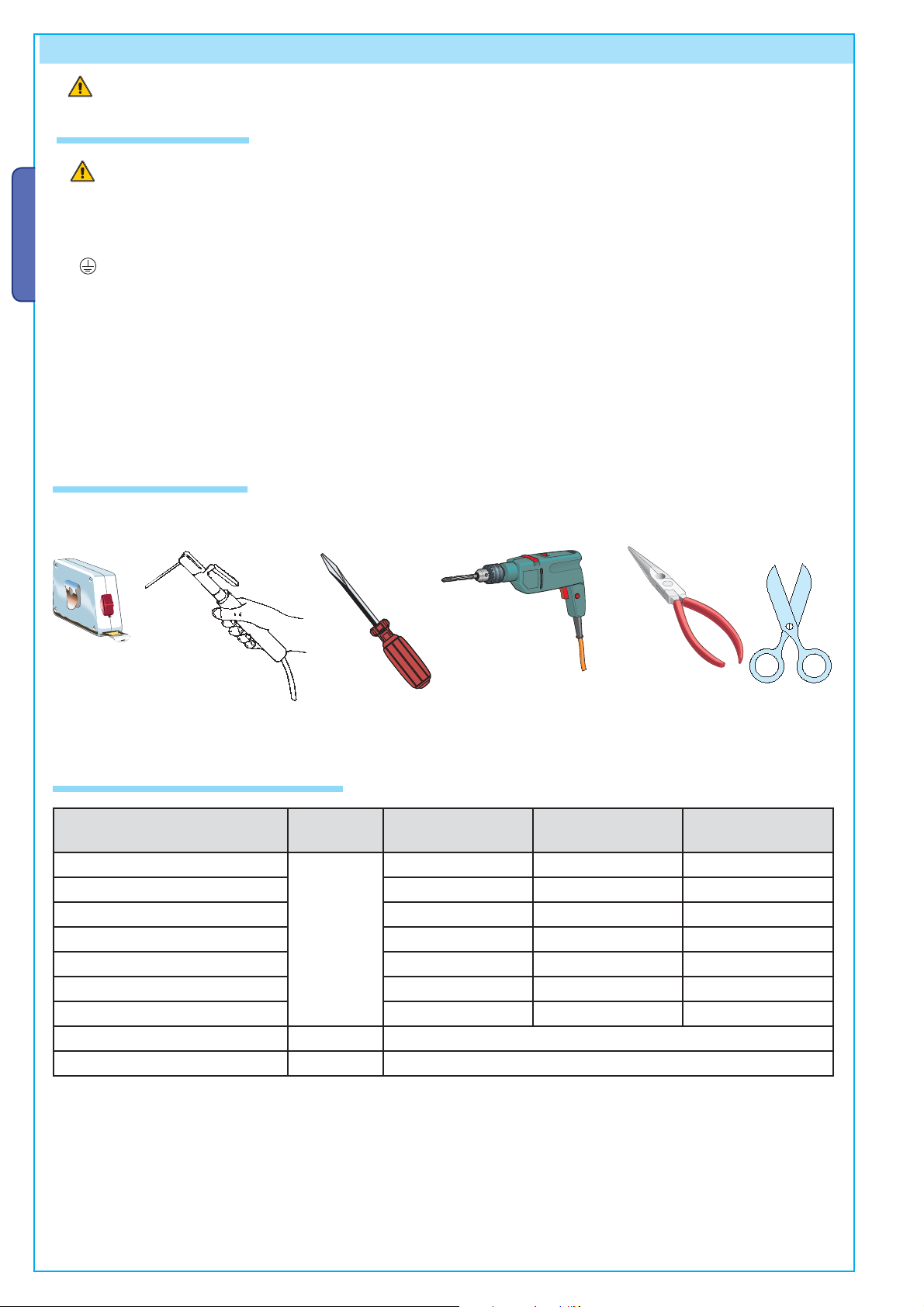
5.2 Tools and materials
Make sure you have all the tools and materials you will need for the installation at hand to work in total safety and compliance with the
current standards and regulations. The following figure illustrates the minimum equipment needed by the installer.
5.3 Cable list and minimum thickness
Connections Type of cable Type of cable
Control panel power supply 230V
3G x 1,5 mm
Motor power supply 230V 4G x 1 mm
Flashing light 2 x 0,5 mm
Photocell transmitters 2 x 0,5 mm
Photocell receivers 4 x 0,5 mm
FROR CEI
20-22
CEI EN
50267-2-1
Accessories power supply 2 x 0,5 mm
Control and safety devices 2 x 0,5 mm
2
2
2
2
2
2
2
Length of cable
10 < 20 m
3G x 2,5 mm
4G x 1,5 mm
2 x 1 mm
2 x 0.5 mm
4 x 0,5 mm
2 x 0,5 mm
2 x 0,5 mm
Encoder connection TWISTATO 3 x 05 mm
Antenna RG58 max. 10 m
2
2
2
2
2
2
2
2
Length of cable
20 < 30 m
3G x 4 mm
4G x 2,5 mm
2 x 1,5 mm
2 x 0,5 mm
4 x 0,5 mm
2 x 1 mm
2 x 0,5 mm
2
2
2
2
2
2
2
N.B.: If the cable length differs from that specified in the table, then you must determine the proper cable diameter in the basis of the
actual power draw by the connected devices and depending on the standards specified in CEI EN 60204-1.
For connections that require several, sequential loads, the sizes given on the table must be re-evaluated based on actual power draw
and distances.
When connecting products that are not specified in this manual, please follow the documentation provided with said products.
0.1 01/2009 © CAME cancelli automatici s.p.a. - The data and information repor ted in this installation manual are susceptible to change at any time and without obligation on C AME cancelli automatici s.p.a. to notif y users.
119DU85 ver.
4 - Manual code:
Pag.
Page 7

5
119DU8 5
0.1
5.4 Standard installation
1) AXO operator
2) Control panel
3) Reception antenna
4) Flashing light
5) Selector switch
6) Photocells
7) Electric cable junction box
8) Mechanical gate stops
9) Photocell column
6
6
ENGLISH
6
4
3
1
8
5
2
1
9
6
8
9
7
5.5 Installing the operator
The following illustrations are only examples, given that the space available for anchoring the operator and accessories may vary
from gate to gate. It is up to the installer, thus, to choose the most suitable solution.
Lay the corrugated tubing needed for the connections deriving from the junction box.
N.B. the number of tubes depends on the type of system and accessories employed.
The data and information reported in this installation manual are susceptible to change at any time and without obligation on CAME cancelli automatici s.p.a. to notify users.
01/2009 © CAM E cancelli automatici s.p.a. -
0.1
ver.
119DU85
:
Manual code
5 -
Pag.
Electric cable junction box
Page 8

6
119DU8 5
0.1
Warning: after establishing the best point to which you will secure the gate bracket, secure the bracket to the pillar and make sure the
quotas shown in the table below are met.
Note: by increasing measure B, the opening angle and gate speed are reduced, while the gearmotor thrust is increased. By increasing
the measure A, the opening angle and gate speed are increases, while the gearmotor thrust is decreased.
ENGLISH
Pillar bracket
Gate bracket
E
E
AX302304 - AX402306 - AX412306
AX71230
Gate leaves of up to 4m
Opening
angle
A
mmB mm
C max mmE
mm
Opening
90° 130 130 70 800
120° 150 80 0 800
120 ° 14 0 100 50 800
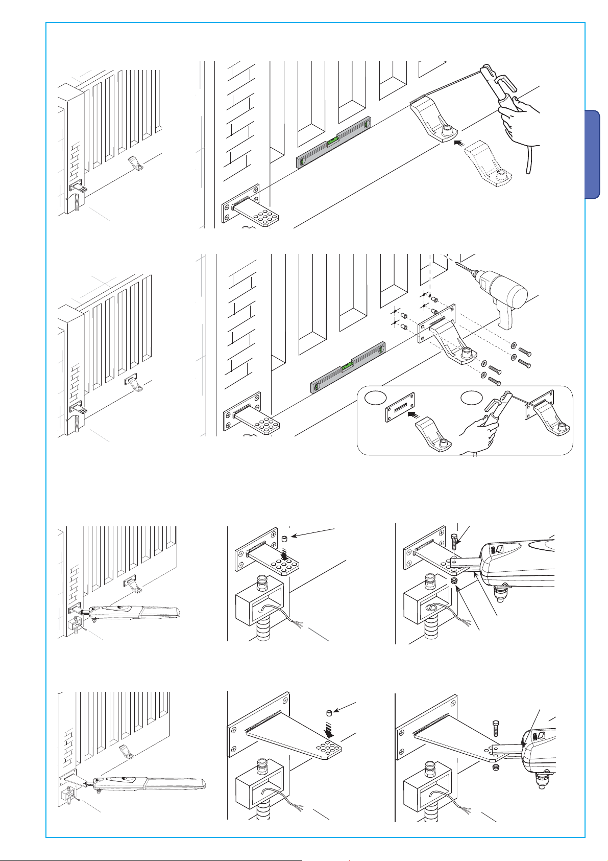
Assemble and weld the two parts of the pillar bracket. Secure the bracket to the point you have chosen with proper plugs and screws
or - if the pillar is made of metal - weld it on.
Gate leaves of up to 7 m
A
angle
mm
90° 200 220 150 1100
120° 220 220 100 1100
B mmC max mmE
mm
1
2
AX302304
AX402306 - AX412306
AX71230
1
0.1 01/2009 © CAME cancelli automatici s.p.a. - The data and information repor ted in this installation manual are susceptible to change at any time and without obligation on C AME cancelli automatici s.p.a. to notif y users.
2
119DU85 ver.
6 - Manual code:
Pag.
Page 9
7
119DU8 5
0.1
Weld the gate bracket to the gate leaf making sure the quotas shown in the table are met.
Note: for AX5024 gearmotors, require an additional 10 mm shim between the gate and the bracket.
Note: on non-metal gate leaves assemble and weld the two parts of the bracket and secure them with proper screws.
Secure the tail joint to the bracket.
ENGLISH
1
2
Insert the bushing (lubricated) into the pillar bracket’s hole. The bracket has holes that allow the opening angle to be changed. Secure
the tail joint to the bracket.
Bushing
The data and information reported in this installation manual are susceptible to change at any time and without obligation on CAME cancelli automatici s.p.a. to notify users.
Screw M8 x 35
Tail joint
AX302304
Nut UNI 7474 M8
AX402306 - AX412306
Bushing
01/2009 © CAM E cancelli automatici s.p.a. -
0.1
ver.
119DU85
:
Manual code
7 -
Pag.
AX71230
Tail joint
Page 10

8
119DU8 5
0.1
Open the gate leaf and insert the pin into the gate bracket and secure it using a washer and nut.
ENGLISH
Gate bracket
UNI6593 Ø8 washer
Screw UNI5739 M8x10
Release the gearmotor (see paragraph on manual release), completely open the gate leaf, loosen the nuts of the opening mechanical
stop and position it up against the attachment pin, then secure it.
Opening
Attachment pin
mechanical stop
Close the gate leaf, loosen the nuts on the closing mechanical stop, place it up against the attachment pin, then secure it.
Attachment pin
Closing mechanical stop
0.1 01/2009 © CAME cancelli automatici s.p.a. - The data and information repor ted in this installation manual are susceptible to change at any time and without obligation on C AME cancelli automatici s.p.a. to notif y users.
119DU85 ver.
8 - Manual code:
Pag.
Page 11
9
119DU8 5
0.1
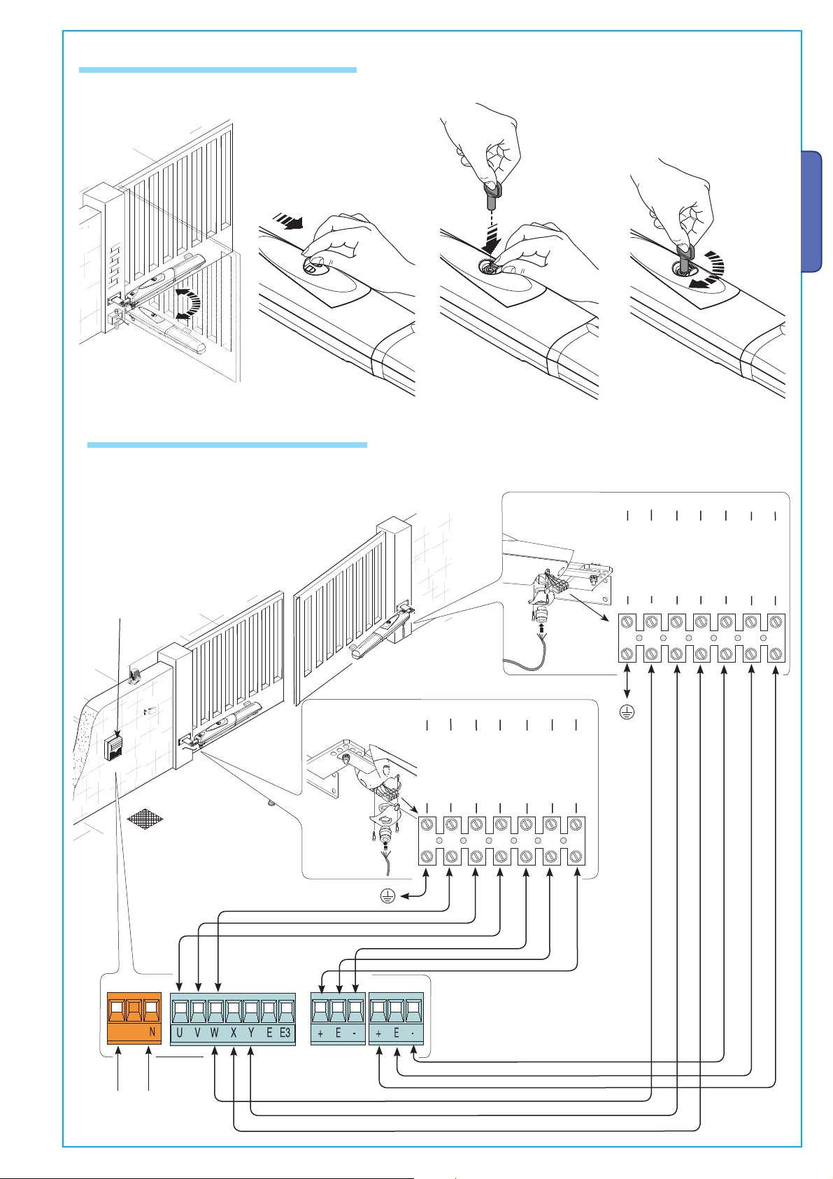
5.6 Manual release of the gearmotor
Slide open the small door that protects the release, insert the tri-lobed key and turn it.
5.7 Connecting to the control panel
ENGLISH
For the electrical connection procedures, use the junction box and branching boxes.
ZM3E Control panel
Connecting the 230V a.c. delayed opening gearmotor
blue
yellow/green
The data and information reported in this installation manual are susceptible to change at any time and without obligation on CAME cancelli automatici s.p.a. to notify users.
Connecting the 230V a.c. delayed closing gearmotor
blue
black
brown
yellow/green
black
green
brown
white
brown
green
white
brown
01/2009 © CAM E cancelli automatici s.p.a. -
0.1
ver.
,
119DU85
:
Manual code
9 -
Pag.
Power
230V a.c. - 50/60 Hz
Encoder B
Encoder A
Page 12

10
119DU8 5
0.1
5.8 Outward opening installation
ENGLISH
E
E
(non-issued)
A
A
Supplementary bracket
TABLE 1 TABLE 2
Opening
A
(mm)
B
(mm)
90° 130 130 800
E
(mm)
Opening
A
(mm)
90° 200 220 1100
B
(mm)
E
(mm)
Weld pillar bracket to the non-issued supplementary bracket, while gate is open, then secure the brackets to the pillar, making sure the
“A” and “B” quotas shown in table 1 are met. Weld, or secure with proper screws, the gate bracket, making sure the “E” quota is met,
as shown in table 1. Finally, secure the gearmotor to the brackets with the issued screws and washers.
1
2
Gate bracket
Pillar bracket
Extra bracket
For AX5024 gearmotors, directly secure the standard issue bracket to the pillar without using the supplementary bracket, while taking
into account the measurements shown in table 2.
Finally, secure the gearmotor to the brackets with the issued screws and washers.
Gate bracket
0.1 01/2009 © CAME cancelli automatici s.p.a. - The data and information repor ted in this installation manual are susceptible to change at any time and without obligation on C AME cancelli automatici s.p.a. to notif y users.
119DU85 ver.
Pillar bracket
10 - Manual code:
Pag.
Page 13

11
119DU8 5
0.1
Fully close the gate-leaf, place the mechanical stop against it with the pin attachment and fi x it in place.
Opening
Attachment pin
mechanical stop
Fully open the gate-leaf, place the mechanical stop against it with the pin attachment and fi x it in place.
ENGLISH
Attachment pin
Connect the gearmotors to the panel as shown in the diagram.
,
The data and information reported in this installation manual are susceptible to change at any time and without obligation on CAME cancelli automatici s.p.a. to notify users.
Power
230V a.c.
50/60 Hz
Closing mechanical stop
white
brown
green
brown
black
blue
yellow/green
Delayed
closing
action
01/2009 © CAM E cancelli automatici s.p.a. -
0.1
ver.
119DU85
:
white
brown
green
brown
black
blue
Delayed
opening
action
yellow/green
Manual code
11 -
Pag.
Page 14
12
119DU8 5
0.1
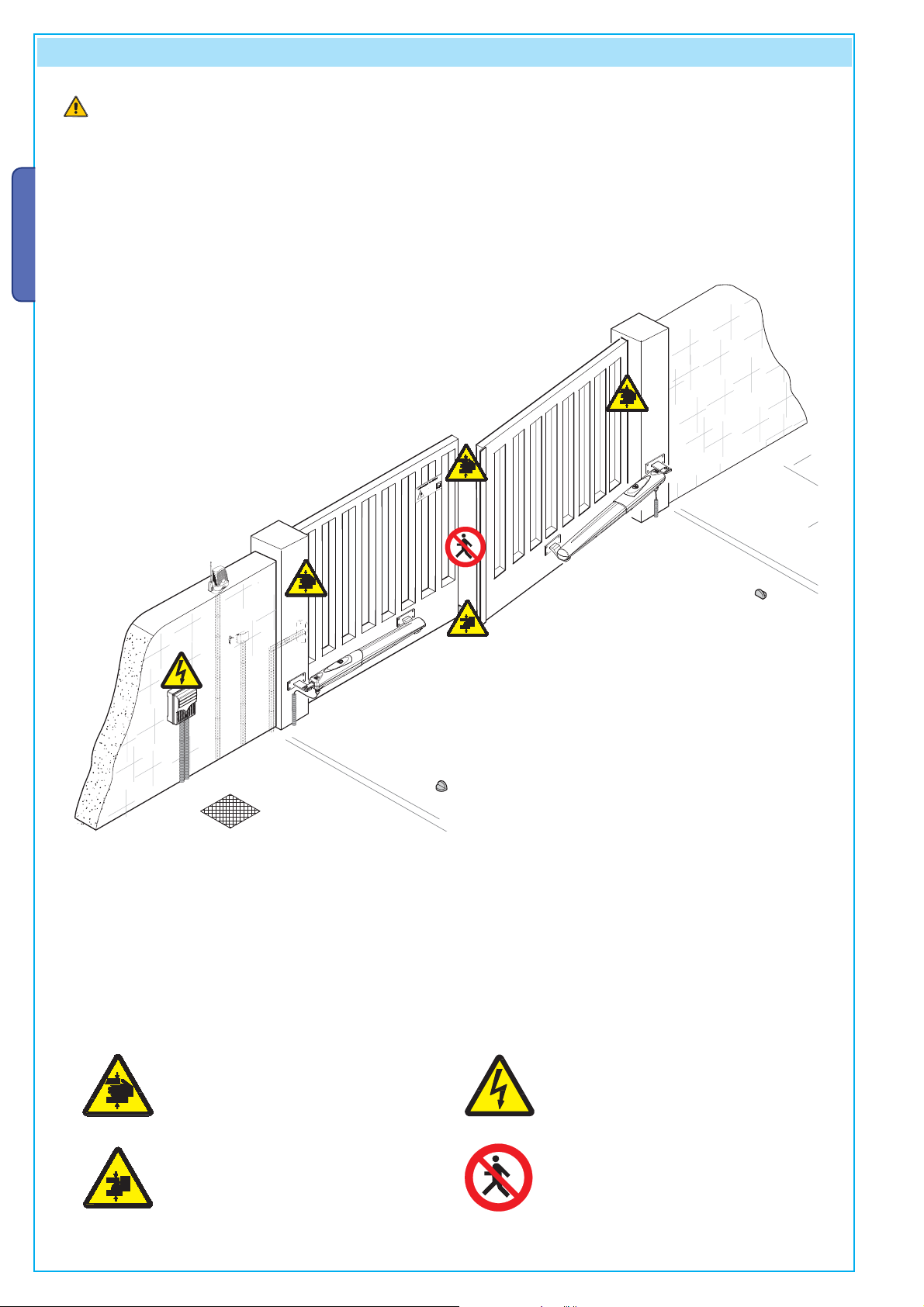
6 Safety instructions
Important safety instructions
This product must only be employed for its originally intended use. The automation installation using these gearmotors requires
adequate safety systems on the gate leaves to detect any obstacles (e.g. sensitive edges), in compliance with EN12445 and EN12453
Technical Standards relative to the impact force generated by the moving gate. Any other use is wrong and potentially dangerous. The
manufacturer cannot be held liable for any damages resulting from wrongful, erroneous or negligent uses.
Avoid working close to the hinges or other moving mechanical parts. Stay out of the opening/closing arc when operator is in motion.
Do not exercise force against the motion of the operator as this could result in potentially dangerous situations.
ENGLISH
Do not allow children to play or loiter within the opening/closing arc of the operator.
Keep remote controls and any other command device out the reach of children, to prevent operator from being activated by accident.
In the event of anomalous behaviour, stop using the operator immediately.
Danger of crushing hands
Danger of crushing feet
Danger! High voltage
No transit during operation
0.1 01/2009 © CAME cancelli automatici s.p.a. - The data and information repor ted in this installation manual are susceptible to change at any time and without obligation on C AME cancelli automatici s.p.a. to notif y users.
119DU85 ver.
12 - Manual code:
Pag.
Page 15

13
119DU8 5
0.1
7 Maintenance
7.1 Periodic maintenance
Periodic maintenance to be carried out by the end-user is as follows: wipe clean the glass surface of the photocells; check that
the safety devices work properly; remove any obstructions.
We suggest checking the state of lubrication and tightness of the anchoring screws on the operator.
To check the efficiency of the safety devices, move an object in front of the photocells when gate is closing. If the operator inverts the
motion or stops, the photocells are working properly.
This is the only maintenance procedure to be carried out with the power source connected.
Before performing any maintenance procedures, cut off the main power, to prevent possible accidents due to gate movement.
To clean the photocells use a water dampened cloth. Do not use solvents or other chemical products which may ruin the devices.
In the event of any strange vibrations or squeaking, lubricate the joints with grease, as shown in the diagram.
Lubricate the endless screw via the hole located under the die-casting of the motor (fig. A)
Fig.A
ENGLISH
Make sure there are no plants within the photocell’s beam, and that the gate motion is free of any obstacles.
The data and information reported in this installation manual are susceptible to change at any time and without obligation on CAME cancelli automatici s.p.a. to notify users.
7.2 Trouble shooting
MALFUNCTIONS POSSIBLE CAUSES CHECK AND REMEDIES
The gate will not open
nor close
01/2009 © CAM E cancelli automatici s.p.a. -
0.1
ver.
The gate opens but
119DU85
will not close
:
The Flashing light
Manual code
does not work
13 -
Pag.
• There is no power
• The gearmotor is released
• The transmitter’s batteries are run down
• The transmitter is broken
• The stop button is either stuck or broken
• The opening/closing button or the selector switch are stuck
• Check that the power is up
• Call assistance
• Replace batteries
• Call assistance
• Call assistance
• Call assistance
• The photocells are engaged • Check that photocells are clean
and in good working order
• Call assistance
• The bulb is burnt • Call assistance
Page 16

14
119DU8 5
0.1
Periodic maintenance log for end-user (every 6 moths).
ENGLISH
Date Notes
Signature
7.3 Extra-ordinary maintenance
The following table serves to note down any extraordinary maintenance, repairs or improvements performed by specialised firms.
N.B.: Any extraordinary maintenance must be performed by specialised technicians.
Extra-ordinary maintenance log
Installer’s stamp Operator name
Date of job
Technician’s signature
Requester’s signature
Job performed _______________________________________________________________________________________
__________________________________________________________________________________________________
____________________________________________________________________________________________
Installer’s stamp Operator name
0.1 01/2009 © CAME cancelli automatici s.p.a. - The data and information repor ted in this installation manual are susceptible to change at any time and without obligation on C AME cancelli automatici s.p.a. to notif y users.
Date of job
Technician’s signature
119DU85 ver.
Requester’s signature
Job performed _______________________________________________________________________________________
__________________________________________________________________________________________________
____________________________________________________________________________________________
14 - Manual code:
Pag.
Page 17

15
119DU8 5
0.1
Installer’s stamp Operator name
Date of job
Technician’s signature
Requester’s signature
Job performed _______________________________________________________________________________________
__________________________________________________________________________________________________
____________________________________________________________________________________________
8 Phasing out and disposal
CAME cancelli automatici s.p.a. employs a UNI EN ISO 14001 certified and compliant environmental protection system at its
plants, to ensure that environmental safeguarding.
We ask you to keep protecting the environment, as CAME deems it to be one of the fundamental points of its market operations
strategies, by simply following these brief guidelines when disposing.
DISPOSING THE PACKING MATERIALS
The packing components (cardboard, plastic, etc.) are solid urban waste and may be disposed of without any particular difficulty, by
simply separating them so that they can be recycled.
Before actions it is always advisable to check the pertinent legislation where installation will take place.
DO NOT DISPOSE OF IN NATURE!
DISPOSING OF THE PRODUCT
Our products are made using different types of materials
The majority of them (aluminium, plastic, iron, electric cables) can be considered to be solid urban waste
They may be recycled at authorised firms
Other components (electrical circuit board, remote control batteries etc.) may contain hazardous waste.
They must, thus, be removed and turned in to licensed firms for their disposal.
Before acting always check the local laws on the matter.
DO NOT DISPOSE OF IN NATURE!
ENGLISH
9 Conformity declaration
The data and information reported in this installation manual are susceptible to change at any time and without obligation on CAME cancelli automatici s.p.a. to notify users.
MANUFACTURER’S DECLARATION OF CONFORMITY
CAME Cancelli Automatici S.p.A.
via Martiri della Libertà, 15
31030 Dosson di Casier - Treviso - ITALY
tel (+39) 0422 4940 - fax (+39) 0422 4941
internet: www.came.it - e-mail: info@came.it
Declares under its own responsibility that the equipments for automatic garage doors and gates listed below:
AX302304 / AX402306 / AX412306 / AX71230
… comply with the National Law related to the following European Directives and to the applicable parts of the
01/2009 © CAM E cancelli automatici s.p.a. -
following Standards.
0.1
IRECTIVES ---
--- D
98/37/CE - 98/79/CE M
ver.
98/336/CEE - 92/31/CEE ELECTROMAGNETIC COMPATIBILITY DIRECTIVE
73/23/CEE - 93/68/CE LOW VOLTAGE DIRECTIVE
89/106/CEE CONSTRUCTION PRODUCTS DIRECTIVE
119DU85
:
Manual code
Reference code to request a true copy of the original: DDF B IT A001i
15 -
Pag.
ACHINERY DIRECTIVE
Pursuant to annex II B of the Machinery Directive 98/37/EC
--- STANDARDS --EN 13241-1 EN 12635 EN 61000-6-2
EN 12453 EN 12978 EN 61000-6-3
EN 12445 EN 60335-1
Do not use the equipment specifi ed here above, before
In full compliance with the Machinery Directive 98/37/EC
IMPORTANT WARNING!
completing the full installation
MANAGING DIRECTOR
Mr. Gianni Michielan
Page 18

CAME F rance S.a.
CAME France S.a.
Nanter re Ce dex -
CAME G mbh S eefel d
Seefel d
CAME A utoma tisme s S.a .
Marsei lle -
CAME G mbh
Korn tal
CAME A utoma tismo s S.a .
Madri d -
CAME A meric as Au tomat ion L lc
Sunris e
CAME A utoma tismo s Cat aluny a S.a .
Sant Vicen c Del Hort s -
CAME M iddle East Fzco
Dubai -
Paf - CAME
Rio D e Mou ro -
CAME P olska Sp.Z o.o
Warsza wa -
CAME U nited King dom L td.
Nottin gham
S.c. C AME R omani a S.r .l.
Bucare st -
CAME B elgiu m Spr l
Lessi nes -
CAME R ussia
Moskva
CAME C ancel li Au tomat ici S .p.a.
Dosso n Di Casie r
CAME N ord s .r.l.
Colog no Mo nzese
CAME S ervic e Ita lia S .r.l.
Dosso n Di Casie r
Assist enza Tecni ca 80 0 295 830
CAME S ud s. r.l.
Napol i
En glish
... .. .. .. ..
...
7, Rue Des Haras
Z.i. Des Hautes Patures
92737
Nanterre Cedex - FRANCE
(+33) 1 46 13 05 05
(+33) 1 46 13 05 00
CAME Gmbh Seefeld
Akazienstrasse, 9
16356
Seefeld
Bei Berlin - DEUTSCHLAND
(+49) 33 3988390
(+49) 33 39883985
CAME Automatismes S.a.
3, Rue Odette Jasse
13015
Marseille - FRANCE
(+33) 4 95 06 33 70
(+33) 4 91 60 69 05
CAME Automatismos S.a.
C/juan De Mariana, N. 17-local
28045
Madrid - SPAIN
(+34) 91 52 85 009
(+34) 91 46 85 442
CAME Automatismos Catalunya S.a.
P.i. Moli Dels Frares N. 23 C/a
08620
Sant Vicenc Del Horts - SPAIN
(+34) 93 65 67 694
(+34) 93 67 24 505
Paf - CAME
Estrada Nacional 249-4 Ao Km 4,35
Cabra Figa - Trajouce
2635-047
Rio De Mouro - PORTUGAL
(+351) 219 257 471
(+35) 219 257 485
Kornwestheimer Str. 37
Munchingen Bei Stuttgart - DEUTSCHLAND
(+49) 71 5037830
(+49) 71 50378383
CAME Americas Automation Llc
1560 Sawgrass Corporate Pkwy, 4th Floor
Sunrise, FL 33323 - U.S.A
(+1) 305 433 3307
(+1) 305 396 3331
CAME Middle East Fzco
Po Box 17131 Warehouse N. Be02
South Zone - Jebel Ali Free Zone -
(+971) 4 8860046
(+971) 4 8860048
CAME Polska Sp.Zo.o
01-237
Warszawa - POLAND
(+48) 22 8365076
(+48) 22 8363296
CAME Gmbh
70825
Korntal
Dubai - U.A.E.
Ul. Ordona 1
CAME United Kingdom Ltd.
Unit 3 Orchard Business Park
Town Street, Sandiacre
Nottingham - Ng10 5du - UNITED KINGDOM
Buftea, Judet Ilfov
(+44) 115 9210430
... ../.... © CAME cancelli automatici s.p.a.
........... ver.
(+44) 115 9210431
CAME Belgium Sprl
Zoning Ouest 7
7860
Lessines - BELGIUM
(+32) 68 333014
(+32) 68 338019
S.c. CAME Romania S.r.l.
B-dul Mihai Eminescu, Nr. 2, Bloc R2
Scara A, Parter, Ap. 3
Bucarest - ROMANIA
(+40) 21 3007344
(+40) 21 3007344
CAME Russia
Leningradskij Prospekt, Dom 80
Pod’ezd 3, offi ce 608
125190,
Moskva - RUSSIA
(+7) 495 937 33 07
(+7) 495 937 33 08
The data and information reported in this installation manual are susceptible to change at any time and without obligation on CAME cancelli automatici s.p.a. to notify users.
English - Manual code:
CAME Cancelli Automatici S.p.a.
Via Martiri Della Libertà, 15
31030
Dosson Di Casier (Tv)
(+39) 0422 4940
(+39) 0422 4941
20093
CAME Nord s.r.l.
Piazza Castello, 16
Cologno Monzese (MI)
(+39) 02 26708293
(+39) 02 25490288
Informazioni Commerciali 800 848095
www.came.it
CAME Service Italia S.r.l.
Via Della Pace, 28
31030
Dosson Di Casier (Tv)
(+39) 0422 383532
(+39) 0422 490044
Assistenza Tecnica 800 295830
CAME Sud s.r.l.
Via F. Imparato, 198
Cm2 Lotto A/7
80146
Napoli
(+39) 081 7524455
(+39) 081 7529109
 Loading...