

Page 1

AXO SERIES
INSTALLATION MANUAL
AX3024U/AX5024U
AUTOMATION FOR SWING GATES
Page 2

Pag.
2
- Manual code:
119DV 32
119 DV 32 ver.
1.0
1.0 0 8/2010 © CAME cancelli automatici s.p.a. - The data and information reported in this installati on manual are susceptible to change at any time an d without obligation on C AME cancelli automatici s.p.a. to notify users.
IMPORTANT UL-325 SAFETY INSTRUCTIONS
AX3024U/ AX5024U
It is extremely important that all parties involved in the installation and operation of the gate operator system read and
understand the following warning instructions.
WARNING – To reduce the risk of injury or death:
1. READ AND FOLLOW ALL INSTRUCTIONS.
2. Never let children operate or play with gate controls. Keep the remote control away from children.
3. Always keep people and objects away from the gate. NO ONE SHOULD CROSS THE PATH OF THE MOVING GATE.
4. Test the gate operator monthly. The gate MUST reverse on contact with a rigid object or stop when an object activates
the non-contact sensors. After adjusting the force or the limit of travel, retest the gate operator. Failure to adjust and
retest the gate operator properly can increase the risk of injury or death.
5. Use the emergency release only when the gate is not moving.
6. KEEP GATES PROPERLY MAINTAINED. Read the installation manual and have a qualified service person make repairs to
gate hardware.
7. The entrance is for vehicles only. Pedestrians must use separate entrance.
8. SAVE THESE INSTRUCTIONS.
Instructions regarding intended installation of the gate operator.
A. Install the gate operator only when:
1. The operator is appropriate for the construction of the gate and the usage Class of the gate.
2. All openings of a horizontal slide gate are guarded or screened from the bottom of the gate to a minimum of
4 feet (1.22m) above the ground to prevent a 2-1/4 inch (57.2mm) diameter sphere from passing through the
openings anywhere in the gate, and in that portion of the adjacent fence that the gate covers in the open
position.
3. All exposed pinch points are eliminated or guarded.
4. Guarding is supplied for exposed rollers.
B. The operator is intended for installation only on gates for vehicles. Pedestrians must be supplied with a separate access
opening. The pedestrian access opening shall be designed to promote pedestrian usage. Locate the gate such that
persons will not come in contact with the vehicular gate during the entire path of travel of the vehicular gate.
C. The gate must be installed in a location so that enough clearance is supplied betweehbe employed, and adjacent
structures when openening and closing to reduce the risk of entrapment. Swinging gates shall not open into public access
areas.
D. The gate must be properly installed and work freely in both directions prior to the installation of the gate operator.
Do not over-tighten the operator clutch or pressure relief valve to compensate for a damaged gate.
E. For gate operators utilizing Type D protection:
1. The gate operator controls must be placed so that the user has full view of the gate area when the gate is not
moving.
2. The placard provided marked in letters at least 1/4 - in (6.4mm) high with the word “WARNING” and the
following statement or equivalent: “Moving Gate Can Cause Serious Injury or Death” shall be placed adjancent
to the controls.
3. An automatic closing device (such as a timer, loop sensor, or similar device) shall not be employed.
4. No other activation device shall be connected.
Page 3

Pag.
3
-
Manual code
:
119DV 32
119 DV 32
ver.
1.0
1.0
08
/
2010
© CAME cancelli automatici s .p.a. -
The data and information repor ted in this installation manual are susce ptible to change at any time and without ob ligation on CAME cancelli automatici s.p.a. to notify users .
F. All openings of a horizontal slide gate are guarded or screened from the bottom of the gate to a minimum of 4
feet (1.22m) above the ground to prevent a 2-1/4 inch (57.2mm) diameter sphere from passing through the openings
anywhere in the gate, and in that portion of the adjacent fence that the gate covers in the open position.
G. All exposed pinch points are eliminated or guarded.
H. The gate must be installed in a location so that enough clearance is supplied between the gate and adjacent
structures when opening and closing to reduce the risk of entrapment. Swinging gates shall not open into public access
area.
I. Controls intended for user activation must be located at least six feet (6’) away from any moving part of the gate and
where the user is prevented from reaching over, under, around or through the gate to operate the controls. Outdoor or
easily accessible controls shall have a security feature to prevent unauthorized use.
K. For gate operators utilizing a non-contact sensor:
1. See instructions on the placement of non-sontact sensors for each type of application.
2. Care shall be exercised to reduce the risk of nuisance tripping, such as when a vehicle, trips the sensor while
the gate is still moving
3. One or more non-contact sensors shall be located where the risk of entrapment or obstruction exists, such as
the perimeter reachable by a moving gate or barrier.
L. For a gate operator utilizing a contact sensor:
1. One or more contact sensors shall be located where the risk of entrapment or obstruction exists, such as the
leading edge, trailing edge, and post mounted both inside and outside of a vehicular horizontal slide gate.
2. One or more contact sensors shall be located at the bottom edge of a vehicular vertical lift gate.
3. One or more contact sensors shall be located at the pinch point of a vehicular vertical pivot gate.
4. A hardwired contact sensor shall be located and its wiring arranged so that the communication between the
sensor and the gate operator is not subjected to mechanical damage.
5. One or more contact sensors shall be located on the inside and outside leading edge of a swing gate.
Additionally, if the bottom edge of a swing gate is greater than 6 inches (152mm) above the ground at any
point in its arc of travel, one or more contact sensors shall be located on the bottom edge.
M. A minimum of two (2) WARNING SIGNS shall be installed, one on each side of the gate where easily visible.
a. Power should be disconnected before installing or servicing a gate operator.
b. All electrical wiring should comply with all local building and electrical codes.
c. All entrapment zones and pinching points should be covered.
d. All safety devices should be tested to assure their proper functionality.
e. The operation of the gate system: operator, controls and safety devices should be reviewed with the end user
or owner, who should be informed of the need for periodic maintenance of the safety and control equipment.
f. All installation operating and safety manuals should be left with the owner.
N. All gate operators systems should include safety devices such as reversing edges or photocells in order to provide
added protection. These safety devices should be installed in accordance to the design and application of the system
being installed.
O. A qualified professional installer should install a gate operator system, its safety accessories and should observe these
minimum procedures:
Page 4

Pag.
4
- Manual code:
119DV 32
119 DV 32 ver.
1.0
1.0 0 8/2010 © CAME cancelli automatici s.p.a. - The data and information reported in this installati on manual are susceptible to change at any time an d without obligation on C AME cancelli automatici s.p.a. to notify users.
CAME AMERICAS AUTOMATION, LLC
MANUFACTURER’S LIMITED 3-YEAR WARRANTY
Veri cation of the warranty period requires copies of receipts or other proof of purchase. Warranty cannot be honored
without proof of purchase. Please retain these records.
Came Americas Automation, LLC (“CAME®”) products are warranted by CAME® against defects in materials and manufacturer
workmanship for a period of thirty-six (36) months from the date of purchase, provided the recommended installation
manual and procedure have been followed. CAME®’s sole obligation under this warranty is limited to repairing or replacing,
at our option, any parts which shall be determined by CAME® to be defective, and is conditioned upon CAME® receiving
notice of any such defect within the warranty period. Claims under this warranty may only be made by a purchaser of CAME®
products (the “Customer”).
CAME® reserves the right to make the nal determination as to whether there is a defect in the materials and/or
workmanship, and whether or not a product is within the warranty period. CAME® is not responsible for any damages or
other costs caused by, or which may result from installation, handling, non-recommended operation, product abuse, or
modi cations not authorized by CAME® or for any damages which may arise out of the use of CAME® products.
CAME® sells its products through authorized distributors. This warranty on CAME® products is NOT VALID if the products
have been purchased from an unauthorized distributor, reseller, online E-tailer ( e.g., E-bay®), or if a product serial number
has been altered, removed, or replaced in any way. To verify that you are buying from an authorized CAME distributor or
reseller please call +1 305-433-3307.
In the case of product failure due to defective material or manufacturer workmanship within the thirty-six (36) months
warranty period, the product will be repaired or replaced (at the manufacturer’s option) at no charge to the Customer, if
returned, freight prepaid, to CAME AMERICAS AUTOMATION, LLC, 11345 NW 122nd Street Medley, Florida 33178.
IMPORTANT: Obtain a Return Goods Authorization (RGA) number before returning item(s) to our facilities by submitting a
warranty claim and request for RGA with our customer service department. Products shipped without an RGA number will
not be accepted. Replacements or repaired parts are covered by this warranty for the remainder of the thirty-six (36) month
warranty for the original product or six (6) months from the date of repair or replacement, whichever is greater. CAME® will
pay shipping costs at the ground transport rate for the return to owner of item(s) repaired under warranty.
The manufacturer will not be responsible for any charges or damages incurred in the removal of the defective parts for
repair, or the reinstallation of these parts after repair. Use of any (00021996.doc V.2) components that are not CAME®
speci ed (e.g. batteries, light bulbs, drive belts, chains or transformers) will void the warranty. This warranty shall be void if
damage to the product(s) was due to improper installation or use, neglet, accident, use of non-CAME® speci ed or approved
components or replacement parts, connection to an improper power source, tampering, or if damage was caused by
lighting, strikes, power surges, wind, re, oor, insects, or other natural agents or disasters.
This warranty gives you speci c legal rights, and you may also have other rights, which vary from state
to state (or jurisdiction to jurisdiction.) CAME's responsibility for malfunctions and defects in equipment
is limited to repair and replacement as set forth in this warranty statement.
THE CUSTOMER ACKNOWLEDGES AND AGREES THAT THIS WARRANTY IS MADE EXPRESSLY IN LIEU OF
ALL OTHER EXPRESS AND IMPLIED WARRANTIES FOR THE PRODUCT(S), INCLUDING BUT NOT LIMITED
TO ANY IMPLIED WARRANTIES AND CONDITIONS OF MERCHANTABLE QUALITY, MERCHANTABILITY,
FITNESS FOR A PARTICULAR PURPOSE, OR ANY OTHER EXPRESS OR IMPLIED WARRANTY ARISING OUT
OF LAW, STATUTE, USAGE OF TRADE OR COURSE OF DEALINGS.
The warranty hereunder is limited in time to the term of the limited warranty period re ected in this
limited warranty. No warranties, whether express or implied, will apply after the limited warranty period
has expired. Some states do not allow limitations on the term of an implied warranty, so this limitation
may not apply to you.
Page 5
Pag.
5
-
Manual code
:
119DV 32
119 DV 32
ver.
1.0
1.0
08
/
2010
© CAME cancelli automatici s .p.a. -
The data and information repor ted in this installation manual are susce ptible to change at any time and without ob ligation on CAME cancelli automatici s.p.a. to notify users .
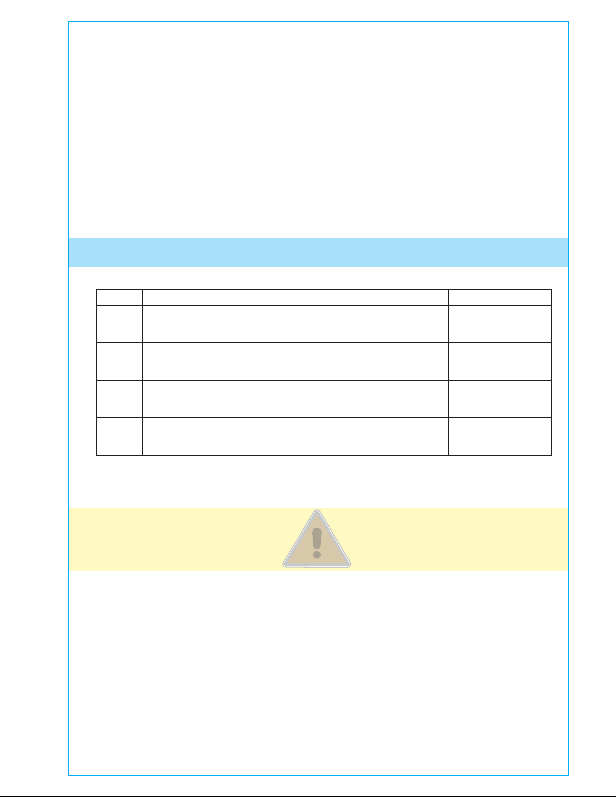
CLASS DESCRIBTION DUTY CYCLE AX3024U / AX5024U
I
Residential Vehicular Gate Operator
Typical use: Home, 1-4 apartment condominium.
Limited public access.
Continuous X
II
Commerical/ General Access Vehicular Gate Operator
Typical use: Condominiums, hotels, parking lots.
No general public access.
Continuous X
III
Industrial/ Limited Access Vehicular Gate Operator
Typical use: industrial location, Factory, Loading Dock.
No general public access.
Continuous X
IV
Restricted Access Vehicular Gate Operator
Typical use: Security area with restricted access.
No general public access.
Continuous X
CAME AUTOMATION GATES UL 325 CLASSES
Power Connection
CAUTION
Be sure that the circuit breaker for the line input power is turned off before connecting the input power to the unit.
Warning: CAME SPA is not responsible for researching and complying with local building codes. Be sure to check these
codes before installation.
The installer must use 14AWG conductors and ½” conduit for the power connection.
CAME® DOES NOT ASSUME, AND SPECIFICALLY DISCLAIMS, ANY LIABILITY OR OBLIGATION WHATSOEVER IN THE SALE OF
THE PRODUCT(S), INCLUDING ANY LIABILITY FOR CONSEQUENTIAL, INCIDENTAL, PUNITIVE OR SPECIAL DAMAGES TO YOU
OR ANY OTHER PERSON OR ENTITY, INCLUDING, WITHOUT LIMITATION, ANY LIABILITY FOR THIRD-PARTY CLAIMS AGAINST
YOU FOR DAMAGES. THE CUSTOMER ACKNOWLEDGES THAT THIS LIMITED WARRANTY PROVIDED IN LIEU OF ALL OTHER
WARRANTIES AND CUSTOMER’S WAIVER OF SPECIAL, INCIDENTAL AND CONSEQUENTIAL DAMAGES IS COMMERCIALLY
NECESSARY AND REASONABLE, AN ESSENTIAL AND MATERIAL ELEMENT OF THIS TRANSACTION, AND UPON WHICH BOTH
THE CUSTOMER AND CAME® HAVE RELIED AND HAVE HAD THE OPPORTUNITY TO NEGOTIATE.
Some states do not allow the exclusion or limitation of incidental or consequential damages, so the above limitation or
exclusion may not apply to you. CAME®‘s liability will be no more than the amount you paid for the product that is the
subject of a claim. This is the maximum amount recoverable under this warranty. The limitations in this section shall apply
whether or not the alleged breach or default is a breach of a fundamental or material condition or term, or a fundamental
or material breach.
Page 6
Pag.
6
- Manual code:
119DV 32
119 DV 32 ver.
1.0
1.0 0 8/2010 © CAME cancelli automatici s.p.a. - The data and information reported in this installati on manual are susceptible to change at any time an d without obligation on C AME cancelli automatici s.p.a. to notify users.
This product is engineered and manufactured by CAME cancelli automatici s.p.a. and complies with current safety
regulations. Guaranteed 36 months if not tampered with.
The gearmotor is made up of two aluminium alloy half shells housing the Encoder gearmotor – which features an electric
blocking mechanism – and an epicyclical reduction system with endless screw.
24V D.C. surface gearmotors:
001AX3024U – irreversible gearmotor with encoder for gate leaves of up to 9.8 ft.
001AX5024U – irreversible gearmotor with encoder for gate leaves of up to 16.4 ft.
Control panel:
ZLJ24U – Multifunction control panel for gates with two swing-leaves with built-in radio decoder
Accessories:
002LB180 – Board to link up two 12V – 7A emergency batteries with battery holding bracket
001LOCK81 – Blocking electro-lock – single cylinder
001LOCK82 – Blocking electro-lock – double cylinder
119RY077 - Tri-lobed Key
2.1 Intended use
1 Legend of symbols
This symbol tells you to read the section with particular care.
This symbol tells you that the sections concern safety issues.
This symbol tells you what to say to the end-users.
2 Intended use and application
The AXO operator is designed to automate swing gates used in residential or condominium settings..
The use of this product for purposes other than those described above and installation executed in a manner
other than as instructed in this technical manual are prohibited.
2.2 Application
3 Reference Standards
The company CAME cancelli automatici is ISO 9001:2000 quality certified; it has also obtained the ISO 14001 environmental
safeguarding certification. CAME engineers and manufactures all of its products in Italy.
This product complies with the following standards: EN 12978, UNI EN 954-1, CEI EN 60335-1, UNI EN 12453, UL325, and
CSA C22.2 NO.247
4.1 Gate Operator
4 Description
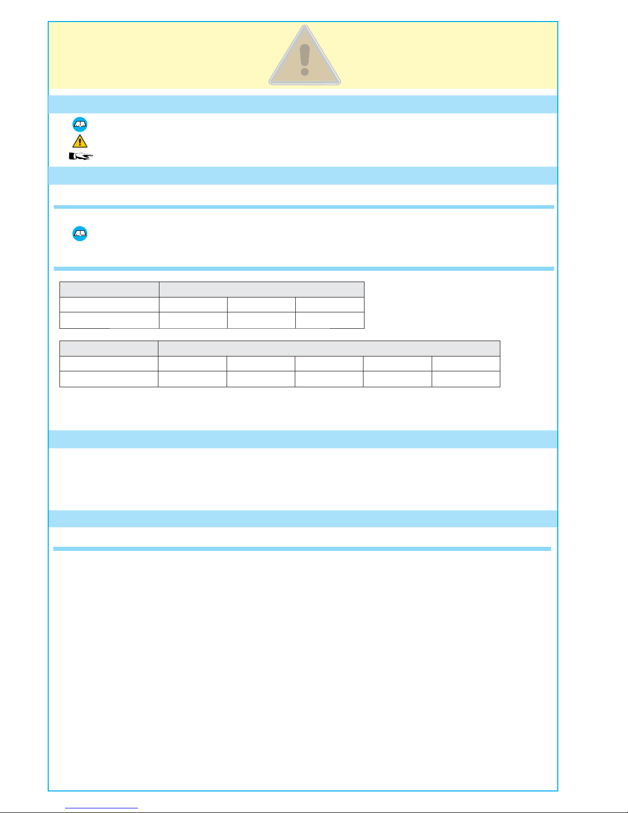
Typ e
AX3024U
Length of gate leaf (ft) 6.5 8.2 9.8
Weight of gate leaf (lb) 1,764 1,323 1,102
* The electrolock must be installed onto the door-leaf.
Typ e
AX5024U
Length of gate leaf (ft) 6.5 8.2 9.8 13* 16.4*
Weight of gate leaf (lb) 2,205 1,764 1,543 1,102 882
“IMPORTANT INSTALLATION, SAFETY INSTRUCTIONS”
“CAUTION: IMPROPER INSTALLATION MAY CAUSE SERIOUS DAMAGE, FOLLOW ALL INSTALLATION INSTRUCTIONS CAREFULLY”
“THIS MANUAL IS ONLY FOR PROFESSIONAL OR QUALIFIED INSTALLERS”
Page 7

31.5
12.8
34.6
3.9
4.8
43.3
46.4
4.8
24.6
3.9
AX3024
(mm)
AX5024
-4°F
131°F
1
8
5
4
2
6
AX3024
AX5024
3
10
8
9
11
12
9
7
2
5
4
6
7
1
13
13
13
14
Pag.
7
-
Manual code
:
119DV 32
119 DV 32
ver.
1.0
1.0
08
/
2010
© CAME cancelli automatici s .p.a. -
The data and information repor ted in this installation manual are susce ptible to change at any time and without ob ligation on CAME cancelli automatici s.p.a. to notify users .
1) Operator
2) Pilaster bracket
3) Gate bracket
4) M8x35 UNI5737 screw for securing pillar bracket
5) Bushing
6) M8 UNI5588 nut for securing pillar bracket
7) Sheath holder
8) Mechanical stop
9) M6X20 UNI5739 screws for mechanical stop
10) Endless screw pin
11) Ø8x24 UNI6593 washer
12) Gate bracket screw for securing to M8x10 UNI5739 pin
13) Securing bracket
14) Small release door
4.2 Technical features
GEARMOTOR AX3024U / AX5024U
Control board power supply: 120V A.C. 50/60Hz
Motor power supply: 24V D.C.
Max draw.: 10A
Power: 240W
Adjustable thrust: 500 - 4500N
Opening time (90°): adjustable
Duty cycle: intensive user
Protection rating: IP44
Operating temperature: -4ºF - 131ºF
4.3 Description of parts
4.4 Dimensions
131 F
-4 F
U
U
31.5
12.8
34.6
3.9
4.8
43.3
46.4
4.8
24.6
3.9
AX3024U
AX5024U
(inches)
(inches)
Page 8

Pag.
8
- Manual code:
119DV 32
119 DV 32 ver.
1.0
1.0 0 8/2010 © CAME cancelli automatici s.p.a. - The data and information reported in this installati on manual are susceptible to change at any time an d without obligation on C AME cancelli automatici s.p.a. to notify users.
Make sure you have all the tools and materials you will need for the installation at hand to work in total safety and
compliance with the current standards and regulations. The following figure illustrates the minimum equipment needed
by the installer.
Note: If the cable length differs from that specified in the table, then you must determine the proper cable diameter in
the basis of the actual power draw by the connected devices and according to the local electrical code standards.
For connections that require several, sequential loads, the sizes given on the table must be re-evaluated based on actual
power draw and distances.
When connecting products that are not specified in this manual, please follow the documentation provided with said
products.
5.3 Cable list and minimum thickness
Connections Type of cable Type of cable
Length of cable
32 < 65 ft
Length of cable
32 < 65 ft
Control panel power supply 1200V
UL LISTED
CABLE/WIRE
3G x 14AWG 3G x 14AWG 3G x 14AWG
Motor power supply 24V
3 x 14AWG 3 x 14AWG 3 x 14AWG
Flashing light
2 x 20AWG 2 x 20AWG 2 x 20AWG
Photocell transmitters
2 x 20AWG 2 x 20AWG 2 x 20AWG
Photocell receivers
4 x 18AWG 4 x 18AWG 4 x 18AWG
Accessories power supply
2 x 20AWG 2 x 20AWG 2 x 20AWG
Control and safety devices
2 x 20AWG 2 x 20AWG 2 x 20AWG
Antenna RG58
max. 32 ft
5.2 Tools and materials
5 Installation
Before installing, do the following:
• Make sure you have suitable tubing and conduits for the electrical cables to pass through and be protected against
mechanical damage.
• Fit tubing to drain away any water leaks which may cause oxidation
•
Make sure that any connections inside the case (that provide continuance to the protective circuit) be fitted with
extra insulation as compared to the other conductive parts inside
• Make sure the structure of the gate is sturdy, the hinges work and that the is no friction between moving and
non-moving parts.
• Make sure there is a mechanical stop for opening and closing.
Installation must be carried out by expert qualified personnel and in full compliance with current regulations.
5.1 Preliminary checks
Page 9

3
2
8
1
1
4
5
6
6
7
8
6
6
9
9
Pag.
9
-
Manual code
:
119DV 32
119 DV 32
ver.
1.0
1.0
08
/
2010
© CAME cancelli automatici s .p.a. -
The data and information repor ted in this installation manual are susce ptible to change at any time and without ob ligation on CAME cancelli automatici s.p.a. to notify users .
Lay the corrugated tubing needed for the connections deriving from the junction box.
Note: the number of tubes depends on the type of system and accessories employed.
The following illustrations are only examples, given that the space available for anchoring the operator and
accessories may vary from gate to gate. It is up to the installer, thus, to choose the most suitable solution.
5.5 Installing the operator
1) AXO operator
2) Control panel
3) Reception antenna
4) Flashing light
5) Selector switch
6) Photocells
7) Electric cable junction box
8) Mechanical gate stops
9) Photocell column
5.4 Standard installation
Electric cable junction box
Page 10

1
2
1
2
E
E
AX3024
AX5024
AX5024
AX3024
Pag.
10
10 - Manual co de:
119DV 32
119 DV 32 ver.
1.0
1.0 0 8/2010 © CAME cancelli automatici s.p.a. - The data and information reported in this installati on manual are susceptible to change at any time an d without obligation on C AME cancelli automatici s.p.a. to notify users.
Gate leaves of up to 9.8 ft
Opening
angle
A
in
B
in
C max
in
E
in
90°
5.11 5.11 2.75 31.5
120 °
5.9 3.15
0
31.5
120 °
5.5 3.93 1.96 31.5
Warning: After establishing the best point to which you will secure the gate bracket, secure the bracket to the pillar and
make sure the quotas shown in the table below are met.
Note: By increasing measure B, the opening angle and gate speed are reduced, while the gearmotor thrust is increased.
By increasing the measure A, the opening angle and gate speed are increases, while the gearmotor thrust is decreased.
Gate leaves of up to 16.4 ft
Opening
angle
A
in
B
in
C max
in
E
in
90°
7. 8 8 . 6 5. 9 4 3. 3
120 °
8.6 8.6 3.9 43.3
Assemble and weld the two parts of the pillar bracket. Secure the bracket to the point you have chosen with proper
plugs and screws or - if the pillar is made of metal - weld it on.
Gate bracket
Pillar bracket
U
U
U
U
Page 11

1
2
AX5024
AX3024
Pag.
11
11 -
Manual code
:
119DV 32
119 DV 32
ver.
1.0
1.0
08
/
2010
© CAME cancelli automatici s .p.a. -
The data and information repor ted in this installation manual are susce ptible to change at any time and without ob ligation on CAME cancelli automatici s.p.a. to notify users .
Tail joint
Bushing
Insert the bushing (lubricated) into the pillar bracket’s hole. The bracket has holes that allow the opening angle to be
changed. Secure the tail joint to the bracket.
Note: On non-metal gate leaves assemble and weld the two parts of the bracket and secure them with
proper screws. Secure the tail joint to the bracket.
Tail joint
Bushing
Screw M8 x 35
Nut UNI 7474 M8
Weld the gate bracket to the gate leaf making sure the quotas shown in the table are met.
Note: for AX5024U gearmotors, require an additional 10 mm shim between the gate and the bracket.
U
U
Page 12

Pag.
12
12 - Manual code:
119DV 32
119 DV 32 ver.
1.0
1.0 0 8/2010 © CAME cancelli automatici s.p.a. - The data and information reported in this installati on manual are susceptible to change at any time an d without obligation on C AME cancelli automatici s.p.a. to notify users.
Close the gate leaf, loosen the nuts on the closing mechanical stop, place it up against the attachment pin, then secure it.
Closing mechanical stop
Attachment pin
Open the gate leaf and insert the pin into the gate bracket and secure it using a washer and nut.
Gate bracket
Release the gearmotor (see paragraph on manual release), completely open the gate leaf, loosen the nuts of the opening
mechanical stop and position it up against the attachment pin, then secure it.
Opening
mechanical stop
Attachment pin
Screw UNI5739 M8x10
UNI6593 Ø8 washer
Page 13

,
.
- .
%.#
- .
%.#
-
.
%.#
-
.
%.#
Pag.
13
13 -
Manual code
:
119DV 32
119 DV 32
ver.
1.0
1.0
08
/
2010
© CAME cancelli automatici s .p.a. -
The data and information repor ted in this installation manual are susce ptible to change at any time and without ob ligation on CAME cancelli automatici s.p.a. to notify users .
Slide open the small door that protects the release, insert the tri-lobed key and turn it.
5.6 Manual release of the gearmotor
For the electrical connection procedures, use the junction box and branching boxes.
5.7 Connecting to the control panel
Power
120V a.c. - 50/60 Hz
Connecting the 24V
d.c. delayed closing
gearmotor
Connecting the
24V d.c. delayed
opening gearmotor
ZLJ24U Control panel
Page 14

E
A
E
A
1
2
Pag.
14
14 - Manua l code:
119DV 32
119 DV 32 ver.
1.0
1.0 0 8/2010 © CAME cancelli automatici s.p.a. - The data and information reported in this installati on manual are susceptible to change at any time an d without obligation on C AME cancelli automatici s.p.a. to notify users.
(non-issued)
Supplementary bracket
Weld pillar bracket to the non-issued supplementary bracket, while gate is open, then secure the brackets to the pillar,
making sure the “A” and “B” quotas shown in table 1 are met. Weld, or secure with proper screws, the gate bracket, making
sure the “E” quota is met, as shown in table 1. Finally, secure the gearmotor to the brackets with the issued screws and
washers.
5.8 Outward opening installation
Opening
A
(in)
B
(in)
E
(in)
90°
5.11 5.11 31.5
Pillar bracket
Extra bracket
Gate bracket
For AX5024U gearmotors, directly secure the standard issue bracket to the pillar without using the supplementary
bracket, while taking into account the measurements shown in table 2.
Finally, secure the gearmotor to the brackets with the issued screws and washers.
Pillar bracket
Gate bracket
Opening
A
(in)
B
(in)
E
(in)
90°
7. 8 8 . 6 43 . 3
TABLE 1 TABLE 2
Page 15

-
.
%.#
-
.
%.#
,
.
- .
%.#
- .
%.#
Pag.
15
15 -
Manual code
:
119DV 32
119 DV 32
ver.
1.0
1.0
08
/
2010
© CAME cancelli automatici s .p.a. -
The data and information repor ted in this installation manual are susce ptible to change at any time and without ob ligation on CAME cancelli automatici s.p.a. to notify users .
Connect the gearmotors to the panel as shown in the diagram.
Fully open the gate-leaf, place the mechanical stop against it with the pin attachment and x it in place.
Fully close the gate-leaf, place the mechanical stop against it with the pin attachment and x it in place.
Opening
mechanical stop
Attachment pin
Closing mechanical stop
Attachment pin
Power
120V a.c.
50/60 Hz
Delayed
closing
action
Delayed
opening
action
Page 16

Pag.
16
16 - Manual code:
119DV 32
119 DV 32 ver.
1.0
1.0 0 8/2010 © CAME cancelli automatici s.p.a. - The data and information reported in this installati on manual are susceptible to change at any time an d without obligation on C AME cancelli automatici s.p.a. to notify users.
6 Safety instructions
This product must only be employed for its originally intended use. The automation installation using these gearmotors
requires adequate safety systems on the gate leaves to detect any obstacles (e.g. sensitive edges), in compliance with
UL325 standards and CSA C22.2 No.247 for both the US and Canada. Any other use is wrong and potentially dangerous.
The manufacturer cannot be held liable for any damages resulting from wrongful, erroneous or negligent uses.
Avoid working close to the hinges or other moving mechanical parts. Stay out of the opening/closing arc when operator
is in motion. Do not exercise force against the motion of the operator as this could result in potentially dangerous
situations.
Important safety instructions
Do not allow children to play or loiter within the opening/closing arc of the operator. Keep remote controls and any
other command device out the reach of children, to prevent operator from being activated by accident.
In the event of anomalous behaviour, stop using the operator immediately.
Danger of crushing hands
Danger of crushing feet
Danger! High voltage
No transit during operation
Page 17

Pag.
17
17 -
Manual code
:
119DV 32
119 DV 32
ver.
1.0
1.0
08
/
2010
© CAME cancelli automatici s .p.a. -
The data and information repor ted in this installation manual are susce ptible to change at any time and without ob ligation on CAME cancelli automatici s.p.a. to notify users .
Periodic maintenance to be carried out by the end-user is as follows: wipe clean the glass surface of the
photocells; check that the safety devices work properly; remove any obstructions.
We suggest checking the state of lubrication and tightness of the anchoring screws on the operator.
To check the efficiency of the safety devices, move an object in front of the photocells when gate is closing. If the
operator inverts the motion or stops, the photocells are working properly.
This is the only maintenance procedure to be carried out with the power source connected.
Before performing any maintenance procedures, cut off the main power, to prevent possible accidents due to gate
movement.
To clean the photocells use a water dampened cloth. Do not use solvents or other chemical products which may ruin the
devices.
In the event of any strange vibrations or squeaking, lubricate the joints with grease, as shown in the diagram.
Lubricate the endless screw via the hole located under the die-casting of the motor (fig. A)
Make sure there are no plants within the photocell’s beam, and that the gate motion is free of any obstacles.
7 Maintenance
7.1 Periodic maintenance
MALFUNCTIONS POSSIBLE CAUSES CHECK AND REMEDIES
The gate will not open
nor close
• There is no power
• The gearmotor is released
• The transmitter’s batteries are run down
• The transmitter is broken
• The stop button is either stuck or broken
• The opening/closing button or the selector switch are stuck
• Check that the power is up
• Call assistance
• Replace batteries
• Call assistance
• Call assistance
• Call assistance
The gate opens but
will not close
• The photocells are engaged
• Check that photocells are
clean and in good working
order
• Call assistance
The Flashing light
does not work
• The bulb is burnt • Call assistance
7.2 Trouble shooting
Fig.A
Page 18

Pag.
18
18 - Manual code:
119DV 32
119 DV 32 ver.
1.0
1.0 0 8/2010 © CAME cancelli automatici s.p.a. - The data and information reported in this installati on manual are susceptible to change at any time an d without obligation on C AME cancelli automatici s.p.a. to notify users.
7.3 Extra-ordinary maintenance
Installer’s stamp Operator name
Date of job
Technician’s signature
Requester’s signature
Job performed _______________________________________________________________________________________
__________________________________________________________________________________________________
____________________________________________________________________________________________
The following table serves to note down any extraordinary maintenance, repairs or improvements performed by
specialised firms.
Note: Any extraordinary maintenance must be performed by specialised technicians.
Installer’s stamp Operator name
Date of job
Technician’s signature
Requester’s signature
Job performed _______________________________________________________________________________________
__________________________________________________________________________________________________
____________________________________________________________________________________________
Extraordinary maintenance log
Date Notes
Signature
Periodic maintenance log for end-user (every 6 moths).
Page 19

Pag.
19
19 -
Manual code
:
119DV 32
119 DV 32
ver.
1.0
1.0
08
/
2010
© CAME cancelli automatici s .p.a. -
The data and information repor ted in this installation manual are susce ptible to change at any time and without ob ligation on CAME cancelli automatici s.p.a. to notify users .
CAME cancelli automatici s.p.a. employs a UNI EN ISO 14001 certified and compliant environmental protection
system at its plants, to ensure that environmental safeguarding.
We ask you to keep protecting the environment, as CAME deems it to be one of the fundamental points of its market
operations strategies, by simply following these brief guidelines when disposing.
DISPOSING THE PACKING MATERIALS
The packing components (cardboard, plastic, etc.) are solid urban waste and may be disposed of without any
particular difficulty, by simply separating them so that they can be recycled.
Before actions it is always advisable to check the pertinent legislation where installation will take place.
DO NOT DISPOSE OF IN NATURE!
DISPOSING OF THE PRODUCT
Our products are made using different types of materials
The majority of them (aluminium, plastic, iron, electric cables) can be considered to be solid urban waste
They may be recycled at authorised firms
Other components (electrical circuit board, remote control batteries etc.) may contain hazardous waste.
They must, thus, be removed and turned in to licensed firms for their disposal.
Before acting always check the local laws on the matter.
DO NOT DISPOSE OF IN NATURE!
8 Phasing out and disposal
Installer’s stamp Operator name
Date of job
Technician’s signature
Requester’s signature
Job performed _______________________________________________________________________________________
__________________________________________________________________________________________________
____________________________________________________________________________________________
MANUFACTURER’S DECLARATION OF CONFORMITY
Pursuant to annex II B of the Machinery Directive 98/37/EC
CAME Cancelli Automatici S.p.A.
via Martiri della Libertà, 15
31030 Dosson di Casier - Treviso - ITALY
tel (+39) 0422 4940 - fax (+39) 0422 4941
internet: www.came.it - e-mail: info@came.it
Declares under its own responsibility that the equipments for automatic garage doors and gates
listed below:
AX3024U / AX5024U
… comply with the National Law related to the following European Directives and to the
applicable parts of the following Standards.
--- D
IRECTIVES ---
98/37/CE - 98/79/CE M
ACHINERY DIRECTIVE
98/336/CEE - 92/31/CEE ELECTROMAGNETIC COMPATIBILITY DIRECTIVE
73/23/CEE - 93/68/CE LOW VOLTAGE DIRECTIVE
89/106/CEE CONSTRUCTION PRODUCTS DIRECTIVE
--- STANDARDS --EN 13241-1 EN 12635 EN 61000-6-2
EN 12453 EN 12978 EN 61000-6-3
EN 12445 EN 60335-1
UL 325 LISTED CSA STD C22.2 No.247
IMPORTANT WARNING!
Do not use the equipment speci ed here above, before
completing the full installation
In full compliance with the Machinery Directive 98/37/EC
MANAGING DIRECTOR
Mr. Gianni Michielan
9 Conformity declaration
Reference code to request a true copy of the original: DDF B IT A001i
Page 20

CAME AMERICA AUTOMATION, LLC
11345 NW 122nd ST
MEDLEY FL 33178
Tel (305)433-3307
Fax (305)396-3331
Manual code:
119DV 32
119 DV 32 ver.
1.0
1.0 0 8/2010 © CAME cancelli automatici s. p.a. - The data and information repo rted in this installation manual are sus ceptible to change at any time and without o bligation on
CAME cancelli automatici s. p.a. to notify users.
 Loading...