

Page 1
CANCELLI AUTOMATICI
A 3000
Automazione esterna per cancelli a battente con motoriduttore A3000
External automatic opening system for wing gates with A3000 gearmotor
Automatisme axtérieur pour portails à battant avec motoréducteur A3000
Drehtorantrieb mit A3000 getriebemotor
Automatizacion exterior para puertas batientes con motorreductor A3000
Documentazione
Tecnica
S23
rev. 0.3
08/2002
©
CAME
CANCELLI
AUTOMATICI
119DS23
230 V
3 x 1,5
4
4 x 1 - RX
7
2 x 1,5
4 x 1
4 x 1,5
6
4
T RG58
4 x 1,5
2 x 1 - TX
1
4
1
5
3 x 1
2 x 1
3
2
8
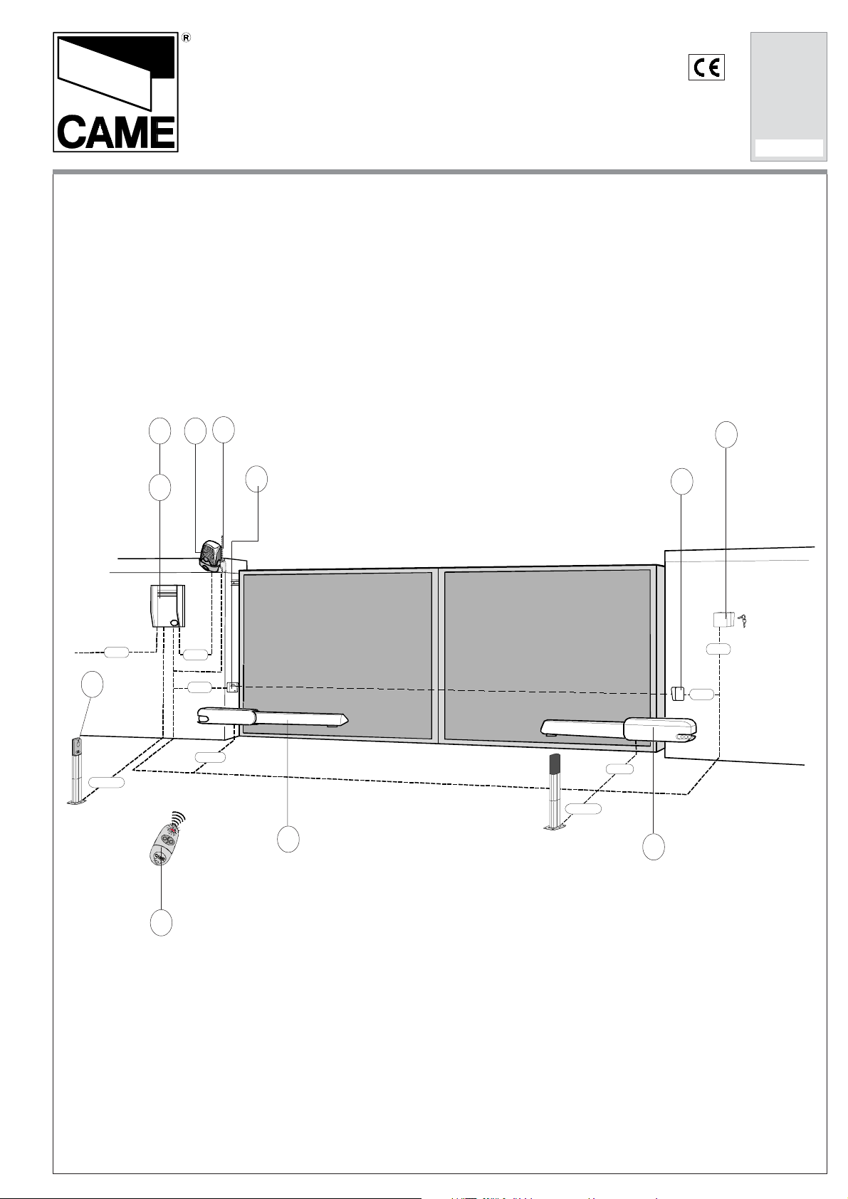
1) Motoriduttore
2) Quadro comando
3) Ricevitore radio
4) Fotocellule di sicurezza
5) Selettore a chiave
6) Antenna
7) Lampeggiatore di
movimento
8) Trasmettitore radio
1) Irreversible gear motor
2) Control panel
3) Radio receiver
4) Safety photocells
5) Key-operated selector
switch
6) Antenna
7) Flashing light indicating
gate movement
8) Radio transmitter
1) Motoréducteur
irreversible
2) Armoire de commande
3) Récepteur radio
4) Photocellules de
sécurité
5) Sélecteur à clé
6) Antenne
7) Clignotant de
mouvement
8) Emetteur radio
1) Irreversibler
Getriebemotor
2) Steuerung
3) Funkempfänger
4) Lichtschranke
5) Schlüsselschalter
6) Antenne
7) Blinkleuchte "Tor in
Bewegung"
8) Handsender
1) Motorreductor
irreversible
2) Cuadro de mando
3) Radiorreceptor
4) Fotocélulas se
seguridad
5) Selector a llave
6) Antena
7) Lámpara intermitente
de movimiento
8) T ransmisor
Page 2

Caratteristiche tecniche -
Tecnichal caracteristics
- Contrôles generales -
Allgemeine Prüfungen -
Controles generales
Tab. 1
MOTORI DUTTORE
GEAR MOTOR
MOTORÉD UCTEUR
GETRIEBEMOTOR
MOTORREDUCTOR
VERSIONE
VERSION
VERSION
VERSION
VERSION
A 3000 1.0 IP 54 10 Kg 230V a.c. 1,2 A 150 W 50 % 1/36 *400÷3000N 19 s 10 µF
Dati relativi ai valori di
alimentazione nominale e a
condizioni di apertura
standard;
(R) Reversibile;
* Servizio intensivo;
** Regolabile mediante quadri
comando CAME
DESCRIZIONE:
- Progettato e costruito
interamente dalla CAME
Cancelli Automatici S.p.a.
- Garantito 24 mesi salvo
manomissioni.
GRADO DI
PROTEZIONE
PROTECTION RATING
DEGRÉ DE
PROTECTION
SCHUTZGR AD
GRADO DE
PROTECCION
Data refers to nominal power
supply and standard conditions
of aperture;
(R) Reversib le;
* Heavy duty cycle;
** Can be adjusted using CAME
control panels;
PESO
WEI GH T
POIDS
GEWICH T
PESO
ALIMENTAZIONE
POWER SUPPLY
ALIMENTATION
STROMVER SORGÜNG
ALIMENTACION
DESCRIPTION:
- Designed and constructed
entirely by CAME Cancelli
Automatici S.p.a
- Guaranteed for 24 months,
unless tampered with by
unauthorized personnel.
CORRENTE
NOMINALE
NOMINAL CURRENT
COURANT
NOMINAL
NENNSTROM
CORRIENTE
NOMINAL
Données relatives aux valeurs
d'alimentation nominale et à des
conditions d'ouverture standard;
(R) Réversible;
* Service intensif;
** Réglable au moyen des
armoires de commande CAME
POTENZA
POWER
PUISSANCE
LEISTUNG
POTENCIA
DESCRIPTION:
- Conçu et construit entièrement par CAME Cancelli
Automatici S.p.A.
- Il est garanti 24 mois sauf
en cas d’altérations.
RAPPORTO DI
INTERMITTENZA
LAVORO
DUT Y CICLE
INTERMITTENCE
DE TRAVAIL
EINSCHALTDAUER
INTERMITENCIA
TRABAJO
Gegevens enkel geldig bij nominale
voeding en normaal gebruik;
(R) Omkeerbaar;
* Intensief gebruik;
** Regelingen gebeuren via een
CAME-stuurkast;
RIDUZIONE
REDUCTION
RATIO
RAPPORT DE
REDUCTION
UNTERSETZUNGS-
VERHÄLTNI S
RELACCION DE
REDUCCION
B
ESCHRIJVING
REGELBARER
:
- Ontworpen en geproduceerd door CAME Cancelli Automatici S.p.A.
- 24 maanden garantie behalve bij verkeerde montage of
foutief gebruik.
SPINTA
PUSH
POUSSÉE
EMPLUJE
TEMPO CORSA
TRAVEL TIME
TEMPS COURSE
LAUFZEI T
TIEMPO DE
RECORRIDO
Datos relativos a los valores de la
tension nominal y a las
condiciones de apertura estándar;
(R) Reversible
* Servicio intensivo;
**Ajustable mediante los cuadros
de mando CAME
DESCRIPCIÓN:
- Diseñado y fabricado
enteramente por CAME
Cancelli Automatici S.p.a
- Garantizado 24 meses,
salvo manipulaciones.
CONDENSATORE
CAPA CIT OR
CONDENSATEUR
KONDENS ATOR
CONDENSADOR
Misure d'ingombro e limiti d'impiego /
Abmessungenunt Einsatzbereich /
Overall dimensions and use limiets /
Dimensiones máximas y limites de empleo
Measures d'encombrent et limites d'emploi
LARGHEZZA ANTA
WI DT H O F WI N G
LARGEUR DU VANTAIL
TORBREITE
ANCHO HOJA
m Kg
2.00 800
2.50 600
3.00 400
PESO ANTA
WEI G HT OF GA TE WI N G
POIDS DU VANTAIL
TORGEWICHT
PESO HOJA
Tab. 2
2
Page 3
Controlli generali -
General control procedure -
Contrôles généraux -
Allgemeine Prüfungen -
Controles generales
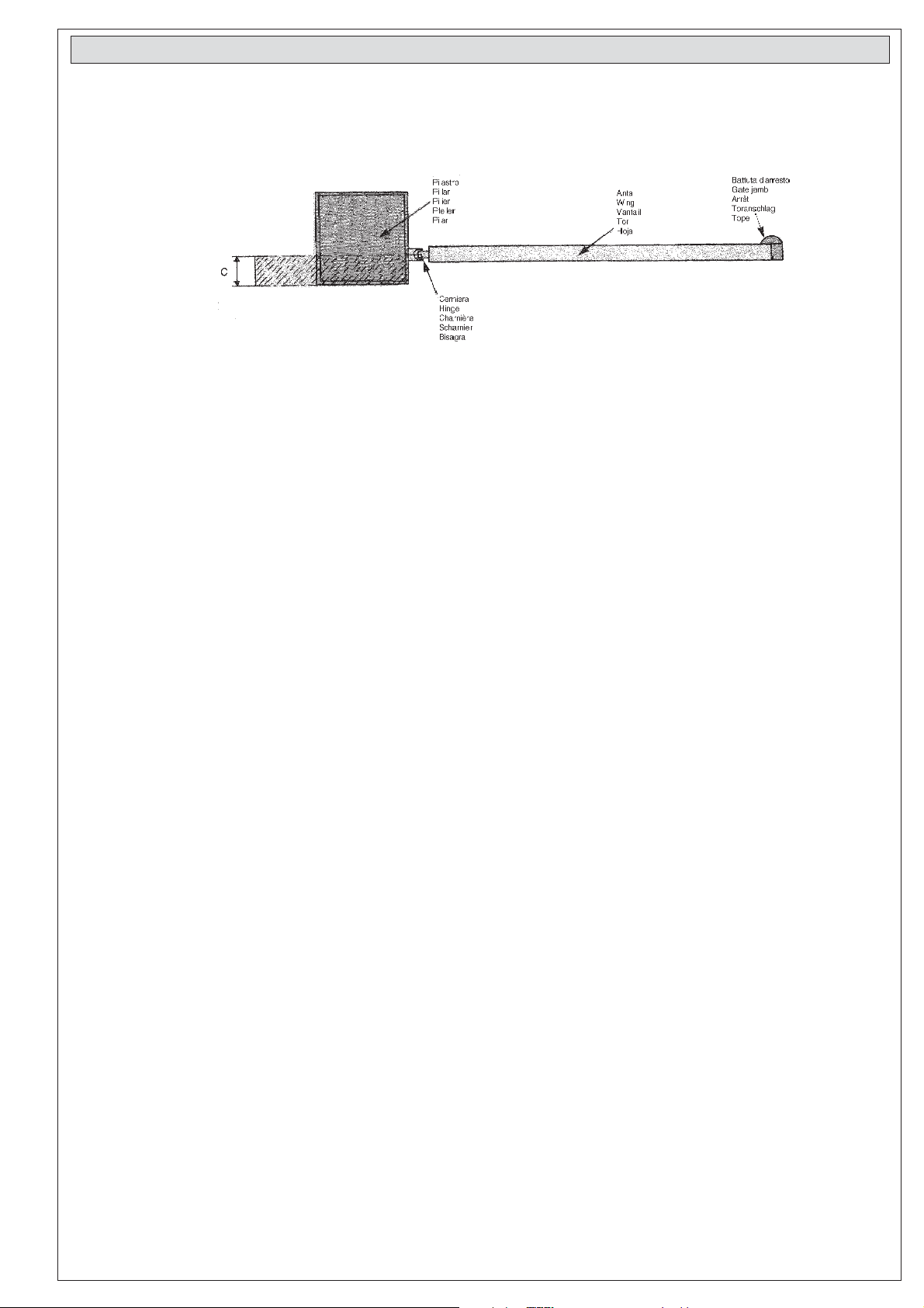
Prima di procedere
all’installazione
dell’automatismo,
controllare:
- che la struttura del
cancello sia
adeguatamente robusta,
le cerniere siano
efficienti e che non vi
sia attrito tra parti fisse
e mobili;
- che la misura C non sia
superiore al valore
indicato nella "Tab. 3",
pag. 4.
In tal caso è necessario
intervenire sul pilastro
in modo da raggiungere
tale misura;
- il percorso dei cavi
elettrici secondo le
disposizioni di
comando e sicurezza;
- che ci sia una battuta
d'arresto meccanico in
chiusura (ben fissata al
suolo) per evitare
l'oltrecorsa anta/
motoriduttore.
Before beginning
installation of the
automation system, check
the following:
- the structure of the gate
must be sufficiently
strong;
the hinges must function
efficiently and there must
be no friction between
the moving parts and
fixed parts;
- measurement C must not
be greater than the value
shown in "Tab. 3" (page
4). If this is the case, it is
necessary to modify the
pillar so that this
measurement
corresponds;
- the electrical wiring path
according to the position
of the control and safety
instruments;
- presence of amechanical
gate stop (securely
anchored to the ground)
in the closed position in
order to prevent the gate
and the reduction gear
from moving beyond the
correct close position.
Avant d’installer l’automatisme, vérifier:
- que la structure du
portail soit robuste et
que les charnières
soient efficaces.
Vérifier également qu'il
n'y ait pas de frottement entre les parties
fixes et celles mobiles;
- que la côte C ne soit
pas supérieure à la
valeur indiquée dans le
"Tab. 3" de la page 4.
Dans ce cas, il est
nécessaire d'intervenir
sur le pilier de façon à
obtenir cette côte;
- le parcours des câbles
électriques selon les
dispositions de commande et de sécurité;
- l'existence d'un dispositif d'arrêt mécanique
en fermeture (bien fixé
au sol) pour éviter la
course excessive vantail/motoréducteur.
V
or Installation der
Automatik kontrollieren:
- die Struktur des Tors
entsprechend robust und
die Scharniere effizient
sind und ob zwischen
fixen und mobilen Teilen
Reibung auftritt;
- das Maß C größer als
der in "Tab. 3", Seite 4,
ange-gebene Wert ist. In
diesem Fall muß au den
Pfeiler so lange
eingewirkt werden, bis
das entspre-chende Maß
erreicht ist;
- die elektrischen Kabel
gemaß den Antriebs und
Sicherheitsvorschriften;
- das Bestehen von einem
mechanischen
Toranschlag bei
Torschließung (muß gut
am Boden verankert
sein) um den Überlauf
Torflügel/Getriebemotor
zu verhindern.
Antes de proceder a la
instalación del
automatismo, controlar:
- la estructura de la puerta
sea lo suficientemente
sólida, las bisagras sean
eficientes y que no haya
rozamiento entre las
piezas fijas y aquéllas
móviles;
- la medida C no sea
superior al dato indicado en la "Tab.3", pág. 4.
En tal caso, es necesario
actuar sobre el pilar
hasta alcanzar dicha
medida;
- el recorrido de los cables
eléctricos según las
disposiciones de mando
y seguridad;
- la existencia de un tope
para el cierre (bien fijado
en el suelo) para evitar
que la hoja/motorreductor llegue más allá de lo
requerido.
3
Page 4

Montaggio -
Assembly
- Montage -
Montagen
- Montaje
Tab. 3
APERTURA - OPE NING
OUVERTURE - ÖFFNUNG
ABERTURA
90° 130 130 60 720
120° 130 110 50 720
1
A (mm) B (mm) C max (mm) E (mm)
Piastra di fissaggio
Fixing plate
Plaque defixation
Bevestiginsplaat
Placa de fijación
Staffa di coda
Rear bracket
Etrier arrière
Beugel
Soporte trasero
B
Pilastro
Pillar
Pilier
Pfelier
Pilar
C
A
Cerniera
Hinge
Chamière
Scharnier
Bisagra
E
Anta pos. chiusura
Wing closed
Vantail position fermee
Poort gesloten
Hoja cerrrada
1a
B
Applicare al pilastro la
piastra di fissaggio con la
staffa di coda (fig. 1)
rispettando le quote A e B
(Tab. 3) tra l'asse della
cerniera e il foro centrale
della staffa.
La staffa di coda è dotata
di ulteriori forature per
variare l'angolo di apertura
del cancello.
N.B.:
aumentando la misura B
diminuisce l'angolo di
apertura con conseguente
diminuzione della velocità
periferica e aumento della
spinta motore sull'anta.
Aumentando la misura A
aumenta l'angolo di
apertura con conseguente
aumento della velocità
periferica e diminuzione
della spinta motore
sull'anta.
A
Attach the fixing plate and
the rear bracket (fig. 1) to the
pilar observing measurement A and B shown in
"Tab. 3", between the hinge
pin and the central hole in
the bracket.
The rear bracket is
equipped with additional
holes to change the opening
angle of the gate.
N.B.:
if measurement B is
increased, the opening
angle is reduced. This
therefore reduces the
peripheral speed and
increases the thrust exerted
by the motor on the gate. If
measurement A is
increased, the angle of
aperture is increased. This
therefore increases the
peripheral speed and
reduces the thrust exerted
by the motor on the gate.
1b
Fixer la plaque de fixation
avec l'étrier arrière sur le
pilier (fig. 1) en respectant les cotes A et B
("Tab. 3") entre l'axe de la
charnière et le trou
central de l'étrier.
L'étriere arrière comprend d'autres perforations pour modifier
l'angle d'ouverture du
portail.
N.B.:
si on augmente la cote B,
l'angle de ouverture
diminue avec, par consequent, une diminution
de la vitesse périphérique et une augmentation de la poussée du
moteur sur le vantail. Si
on augment la cote A,
l'angle d'ouverture augmente avec, par conséquent, une augmentation
de la vitesse périphérique et une diminution
de la poussée du moteur
sur le vantail.
Boccola
Bushing
Doullie
Bus
Casquillo
Den hinteren Bügel mit der
entsprechenden Klemmplatte (Abb. 1) unter
Einhaltug der Maße A und
B ("Tab. 3"), und zwar dem
Achsenabstand zwischen
zentraler Bügelbohrung
und Torangelzapfen, am
Torpfeiler befestigen. Der
hinteren Bügel ist mit einer
Reihe von Bohrungen
versehen, um eine
Änderung des Toröffnungswinkels zu erlauben.
Wichtig!
Beachten Sie bitte, daß bei
Erhöhen des Maßen B der
Toröffnungswinkel und
demzufolge auch die
periphärische Torlaufgeschwindigkeit vergrößert
und der auf den Torflügel
ausgeübte Motorschub
reduziert.
M8x38
M8
Snodo di coda
Rear joint
Articulation arriere
Beugel
Articulacìon trasera
Aplicar al pilar la placa de
fijación mediante el
soporte trasero (fig. 1)
respetando las cotas A y
B ("Tab. 3") entre la
bisagra y el agujero
central de soporte. El
soporte trasero está
dotado de otros agujeros
para variar el ángulo de
apertura de la puerta.
N.B.:
aumentando la medida B,
se reduce el ángulo de
apertura y por
consiguiente la velocidad
periférica mientras
aumenta el empuje del
motor sobre la hoja.
Aumentando la medida A,
aumenta también el
ángulo de apertura y por
consiguiente la velocidad
periférica mientras se
reduce el empuje del
motor sobre la hoja.
4
Page 5

Spessore
Thickness
Epaisseur
Starke
Espesor
Livellare la staffa
Level the braket
Mise de niveau de l’étrier
Beugel Vitlijnen
Nivelar el soporte
E
Piastra di fissaggio
Fixing plate
Plaque de fixation
Bevestigingsplaat
Placa de Fijación
Staffa di testa
Front brac ket
Etrier avant
Beugel
Soporte delantero
A cancello chiuso, applicare sull'anta la piastra di fissaggio con la staffa di testa, in asse orizzontale con la staffa di coda rispettando la misura
E.
With the gate closed, attach the fixing plate with the front bracket to the gate wing. The anchor plate must be horizontally aligned with the
rear bracket and measurement E must be observed.
Lorsque le portail est fermé, fixer la plaque de fixation avec l'étrier avant sur le vantail, de façon à obtenir un axe horizontal avec l'étrier arrière,
en respectant la côte E.
Bei geschlossenem Tor den vorderen Bügel mit der entsprechenden Klemmplatte am Torflügel in horizontaler Achse mit dem Vorderbügel
und unter Einhaltung des Maßes E befestigen.
Con la puerta cerrada, incorporar a la hoja la placa de fijación mediante el soporte delantero, en línea horizontal con el soporte trasero,
respetando la medida E.
Carter
Afdekkap
Carter
Casing
Schutzhaube
Dado M8 autobloccante
M8 locknut
Ecrou de sureté M8
Verz egelde moer
Tuer ca M8 de seguridad
M8x50
Stelo
Rod
Tige
Stang
Vástago
Vite senza fine
Worm-gear
Vis sans fin
Wormwiel
Tornillo sin fin
M8x10
Svitare le due viti di fissaggio del carter ed estrarlo.
Remove thje two screws which hold the casing in position and remove the rod.
Dévisser les deux vis de fixation du carter et enlever la tige.
Beide Schutzhubenbefesigungsschrauben lösen und die Haube erausziehen.
Aflojar los dos tornillos de fijación del cárter y sacarlo.
Svitare le due viti di fissaggio dello stelo ed estrarlo.
Remove thje two screws which hold the rod in position and remove the rod.
Dévisser les deux vis de fixation de la tige et enlever la tige.
Beide Schutzhubenbefesigungsschrauben lösen und dieStange herausziehen.
Aflojar los dos tornillos de fijación del vástago y sacarlo.
Procedere al montaggio del motoriduttore alle due staffe.
Install the gear motor on the two brackets
Réaliser le montage du motoréducteur sur les deux étriers.
Getriebemotor auf beide Bügel montieren.
Montar el motorreductor en los dos soportes.
N.B: è consigliabile lubrificare (con grasso neutro) la vite senza fine e la boccola al momento dell'installazione; non sarà più necessaria alcuna
manutenzione successiva.
N.B: use neutral grease to lubricate the worm-gear and the washer at the moment of installation. No subsequent maintenance is necessary.
N.B: il est recommandé de lubrifier la vis sans fin et la rondelle au moment de l'installation (avec de la graisse neutre). Par la suite, plus aucun
entretien ne sera nécessaire.
N.B: Es empfiehlt sich, das Schnecke und der Unterlegscheibe bei der Montage mit neutralem Schmierfett zu schmieren; später wird keine Wartung
mehr nötig sein.
Nota: es aconsejable lubricar (con grasa neutra) el tornillo sin fin y la arandela en el momento de la instalación: sucesivamente no será
necesario ningún mantenimiento.
5
Page 6

REGOLAZIONE MICROINTERRUTT ORE STOP IN APERTURA /
ADJUSTING THE STOP MICROSWITCH FOR THE APERTURE MOVEMENT
RÉGLAGE DU MICRO-INTERRUPTEUR DE STOP DANS LA PHASE D'OUVERTURE/
REGULACION DEL MICROINTERRUPTO R DE STOP EN LA FASE DE APER TURA
Slitta azionamento microinterruttore
Microswitch actuation runner
Glissière d’actionnement du microcontact
Mikroschalterantriebsschiene
Corredera accionamiento microinterruptor
Asta porta-microinterruttore
Support plate microswitch
Tôle porte-microinterrupteur
Bevestiging
Chapa porta-microinterruptor
Gruppo microinterrutore
Microswitch unit
Groupe microcontact
Mikroschaltergruppe
Grupo microinterruptor
EISTELLUNG DES STOP-MICROSCHALTER IN DER OFFNUNGSPHASE
Vite senza fine
Worm-gear
Vis sans fin
Wormwiel
Tornillo sin fin
Madrevite
Screw-nut
Vis-mère
Mutterrschraube
Tornillo tuerca
Vite di fissaggio
Fixing screw
Vis de fixation
Bevestigingsschroet
Tornillo de fijación
Sbloccare il
motoriduttore e
portare l'anta in
posizione di apertura
massima desiderata.
Svitare le viti di
fissaggio del gruppo
microinterrutore.
Far scorrere il gruppo
microinterruttore
sull'asta porta
microinterruttore fino
a raggiungere
l'inserimento dello
stesso mediante
contatto sulla slitta
azionamento gruppo
microinterruttore.
Fissare il
microinterruttore
agendo sulle
rispettive viti.
- Release the gearmotor
and move the door to the
maximum desired open
position.
Loosen the fixing screws
of the microswitch unit.
Slide the microswitch
unit along the
microswitch-support rod
until it is inserted by
contact on the
microswitch unit
actuation runner.
Fix the microswitch by
tightening the respective
screws.
- Débloquer le
motoréducteur et
mettre la porte dans la
position d’ouverture
maximum voulue.
Dévisser les vis qui
fixent le groupe
microcontact.
Faire glisser ce groupe
sur la tige porte
microcontact jusqu’à ce
qu’il soit bien inséré en
touchant la glissière
d’actionnement du
microcontact.
Fixer le microcontact
en agissant sur les vis
correspondantes.
Den Getriebemotor
entsperren und den
Torflügel in die
gewünschte weiteste
Öffnungsstellung bringen.
Die Befestigungsschrauben
der Mikroschaltergruppe
lösen.
Die Mikroschaltergruppe
auf der
Mikroschalterstange so
weit gleiten lassen, bis
dieselbe durch Kontakt auf
der MikroschalterAntriebsschiene einrastet.
Den Mikroschalter mit den
entsprechenden Schrauben
befestigen.
- Desbloquee el
motorreductor y
coloque la hoja en la
posición de apertura
máxima deseada.
Desenrosque los
tornillos de fijación del
grupo microinterruptor .
Haga deslizar el grupo
microinterruptor sobre
la varilla portamicrointerruptor hasta
que este se introduzca
por contacto sobre la
corredera de
accionamiento del
grupo microinterruptor.
Fije el microinterruptor
apretando los tornillos
correspondientes.
6
Page 7

Sblocco a chiave personalizzata -
Entriegelungs mit privatschlüssel
Personalized key release
- Desbloqueo mediante llave personalizada
- Déblocage avec clé personnalisée
Chiave
Key
Clefs
Sleuten
Llave
C
A
M
E
180
Pour débloquer (à effectuer lorsque le
moteur est arrêté):
1 - soulever la porte;
2 - introduire et tourner la clé qui débloque
immédiatement le vantail;
3 - pousser ou tirer le vantail manuellement.
Pour bloquer à nouveau le vantail, il suffit
de réintroduire la clé, et de la tourner.
Sportellino
Access door
Porte
Deurtje
Portillo
Zur Entriegelung (der Entriegelungs-
vorgang muß bei ausgeachaltetem) Motor
ausgefürt werden):
1 - Den Abdeckplatte hocheben;
2 - Den Privatschlüssel einführen un drehen
das Tor ist sofort entriegelt;
3 - Das Tor von Hand offnen bzw.schließen.
Zur neurlichen Verriegelung des
Torflugels genugt, den schlüssel wieder
einzufuhren und zu drehen.
Per sbloccare (l'operazione di sblocco
va effettuata a motore fermo):
1 - sollevare lo sportellino;
2 - inserire e girare la chiave che
istantaneamente sblocca l'anta;
3 - spingere o tirare l'anta manualmente.
Per bloccare nuovamente l'anta è
sufficiente reinserire e girare la chiave
Releasing the unit (perform this step with
the motor stopped):
1 - raise the access door;
2 - insert and turn the key. The gate will be
released immediately;
3 - push or pull the gate manually.
The re-lock the gate, simply insert and
turn the key.
Para desbloquear (esta operación se
debe efectuar con el motor parado):
1 - levantar el portillo;
2 - introducir y girar la llave que
enseguida desbloquea la hoja;
3 - empujar o tirar la hoja manualmente.
Para bloquear de nuevo la hoja, es
suficiente volver a introducir y girar la
llave.
Applicazione per aperture verso l'esterno -
Für nach außen öffnende Tore
E
B
Staffa supplementare
Supplementary bracket
Etrier supplementaire
Bevestigines - plaat
Soporte adicional
Rilevare le quote A e B
(Tab. 4).
Fissare la staffa di coda
integrandola con una
staffa supplementare e
applicarla al pilastro.
Aprire il cancello (max
90°), rilevare la quota E
(Tab. 4) e fissare all'anta
la staffa di testa.
Procedere ai collegamenti elettrici come da fig. 2,
adattare e regolare adeguatamente i
microinterruttori.
Measure the lenght of "A"
and "B" (see "Tab.4").
Attach the rear bracket
together with a
supplementary bracket
and fasten both to the
column.
Open the gate (maximum
90°) and measure "E"
("Tab. 4"). Fasten the front
bracket to the gate.
Connect the wiring as
shown in fig. 2 . Adjust the
position of the
microswithces.
A
Application for outside aperture
- Aplicación para apertura hacia exterior
Esterno
- Outside-
Insoide
Interno -
Relever les cotes A et B
(Tab. 4).
Fixer l'étrier arrière en lui
ajoautant un étrier
supplémentaire et
appliquer l'étrier sur le
piller.
Ouvrir le portail (max
90°), relever la cote E
(Tab. 4) et fixer l'étrier
avant sur le vantail.
Réaliser les
branchements
électriques de la manière
représentée sur le fig. 2,
puis adapter les microinterrupteurs et les
régler convenablement.
Extérieur -
- Intèrieur -
Binnen -
- Application pour des ouvertures vers l'extérieur
Tab. 4
A 130 mm
130 mm
720 mm
Determinar las medidas
A y B (Tab. 4).
Fijar el soporte trasero
en el pilar, tras haberlo
integrado por oltro
adicional.
Abrir la puerta (max 90°),
determinar la medida E
(Tab. 4) y fijar en la hoja
el soporte delantero.
Proceder a la conexiones
eléctricas de acuerdo
con las fig. 2, adaptar y
ajustar oportunamente
los microinterruptores.
Buiten -
Exterior
Interior
A und B messen (Tab. 4).
Hinteren Bügel mit Hilfe
eines zusätzlichen Bügels
befestigen und am Pfosten
anbringen.
Das Tör öffnen (max 90°),
E messen (Tab. 4) und der
vorderen Bügel am
Torflügel befestigen.
Die elektrischen
Anschlüsse gemäß Abb. 2
ausfüren und die
Mikroschalter
entsprechend einstellen.
B
E
7
Page 8

Fig. 2
U
M
W
V
Morsettiera motore
Massa
Ground
Masse
Aarding
Tierra
V
U
UV
XY
W
W
W
Motor terminal block
Plaque à bornes du moteur
Aansluitklemmen motor
Caja de bornes para el motor
Morsettiera quadro comando
Control panel terminal block
Plaque à bornes du armoire de commade
Aansluitklemmen stuurprint
Caja de bornes cuadro de mando
Manutenzioni periodiche:
Il gruppo non necessita
di alcuna manutenzione
specifica. Solo come
misura cautelativa è
opportuno controllare il
cavo elettrico collegato al
motore, lubrificare lo
snodo di coda e la vite
senza fine.
Manutenzione periodica /
- Lubrificare la vite
senza fine e i perni di
rotazione;
- Controllare le viti di
fissaggio;
- Verificare l'integrita' dei
cavi di collegamento.
Periodic maintenance :
This unit requires no
specific maintenance.
However, as a precaution,
it is advisable to check the
electrical cable
connected to the motor,
lubricate the rear joint and
the worm-gear at regular
intervals.
- Lubricate the worm
screw and the rotating
pins;
- Ceck the clamps
screws;
- Ceck the connection
cable's soundness.
Periodic maintenance /
- Graisser la vis sans fin
et les axes de rotation;
- Contrôler les vis de
fixation;
- Contrôler l'intégrité des
câbles de branchement.
Entretiens périodiques :
Le groupe ne nécessite
aucun entretien
particulier. Cependant
comme mesure de
prudence il convient de
vérifier le
câble électrique relié au
moteur, lubrifier
l'articulation arrière et la
vis sans fin.
Entretien periodique/
Regelmäßige Wartung :
Die Anlage bedarf keiner
speziellen Wartung. Nur als
Sicherheitsmaßnahme und
bei starker Beanspruchung
und
Dauerbetrieb sollte das am
Motor angeschlossene
Kabel geprüft, das
Endgelenk und das
Schnecke.
RegelmÄßige wartung
Smeer regelmatig het
-
wormwiel en de
draaipunten
- Controleer de
bevestigingen
- Controleer de staat van
de aansluitingskabels
Mantenimiento periódico:
El conjunto no necesita
ningún mantenimiento
específico. Sólo como
medida cautelar es
conveniente controlar el
cable conectado al motor,
engrasar la articulación
trasera y el tornillo sin fin.
/ Mantenimiento periódico
- Lubrique el tornillo sin
fin y los pernos de
rotación;
- Controle los tornillos
de sujeción;
- Controle el estado de
los cables de conexión.
Tutti i dati sono stati controllati con la massima
cura. Non ci assumiamo comunque alcuna responsabilità per eventuali errori od omissioni.
ASSISTENZA TECNICA
NUMERO VERDE
800 295830
www.came.it
E-MAIL
CANCELLI AUTOMATICI
CAME CANCELLI AUTOMATICI S.P.A.
DOSSON DI CASIER (TREVISO)
(+39) 0422 4940 (+39) 0422 4941
info@came.it
All data checked with the maximum care.
However, no liability is accepted for any error or
omission.
SISTEMA Q U ALITÀ
CERTIFICATO
EB
W
Toutes les données ont été contrôlées très
soigneusement. Nous n’assumons de toute
façon aucune responsabilité pour les erreurs
ou omissions éventuelles.
CAME LOMBARDIA S.R.L.______COLOGNO M. (MI)
(+39) 02 26708293 (+39) 02 25490288
CAME SUD S.R.L. ___________________NAPOLI
(+39) 081 7524455 (+39) 081 7529109
CAME (AMERICA) L.L.C.____________MIAMI (FL)
(+1) 305 5930227 (+1) 305 5939823
CAME AUTOMATISMOS S.A__________MADRID
(+34) 091 5285009 (+34) 091 4685442
CAME BELGIUM__________________LESSINES
(+32) 068 333014 (+32) 068 338019
Die Daten wurden mit höchster Sorgfalt geprüft.
Für eventuelle Fehler oder Auslassungen
übernehmen wir keine Haftung.
Todos los datos se han controlado con la máxima
atención. No obstante no nos responsabilizamos
de los posibles errores u omisiones.
CAME FRANCE S.A.____NANTERRE CEDEX (PARIS)
(+33) 01 46130505 (+33) 01 46130500
CAME GMBH________KORNTAL BEI (STUTTGART)
(+49) 07 11839590 (+49) 07 118395925
CAME GMBH____________SEEFELD BEI (BERLIN)
(+49) 03 33988390 (+49) 03 339885508
CAME PL SP.ZO.O______________WARSZAWA
(+48) 022 8365076 (+48) 022 8369920
CAME UNITED KINGDOM LTD___NOTTINGHAM
(+44) 0115 9210430 (+44) 0115 9210431
 Loading...