

Page 1
IN-GROUND OPERATOR FOR SWING GATES
FROG SERIES
INSTALLATION MANUAL
FROG-A 230V
Page 2
“IMPORTANT INSTALLATION, SAFETY INSTRUCTIONS”
“CAUTION: IMPROPER INSTALLATION MAY CAUSE SERIOUS DAMAGE, FOLLOW ALL INSTALLATION INSTRUCTIONS CAREFULLY”
“THIS MANUAL IS ONLY FOR PROFESSIONAL OR QUALIFIED INSTALLERS”
1 Legend of symbols
This symbol tells you to read the section with particular care.
This symbol tells you that the sections concern safety issues.
This symbol tells you what to say to the end-users.
ENGLISH
2 Intended use and application
2.1 Intended use
The FROG operator was engineered to power residential and condominium swing gates.
The use of this product for purposes other than those described above and installation executed in a manner other
than as instructed in this technical manual are prohibited.
2.2 Limits to use
For intensive use and condominiums: max weight of the gate 400kg with max length of 3.5m
3 Reference Standards
For its quality processes management CAME cancelli automatici is ISO 9001:2000 certified, and for its environmental management it is ISO 14001 certified. CAME engineers and manufactures all of its products in Italy.
This product complies with the following standards: see declaration of conformity.
4 Description
4.1 Operator
This product is engineered and manufactured by CAME CANCELLI AUTOMATICI S.p.A. and complies with current safety regulations. Guaranteed 24 months if not tampered with.
The operator is made up of a foundation box, a release assembly, a gearmotor and a transmission arm.
The foundation casing is made of 1.5 mm thick ABS plastic on the sides and of 4mm galvanised steel on the bottom plate. On the
inside is the release assembly with a customised, manual-release key and the gearmotor – made of a cast aluminium shell, inside
of which operates an irreversible, gear-ratio and, endless screw plus helical crown system. A transmission arm is connected to
the gearmotor.
4.2 Technical features
FROG
Motor power supply : 230 A.C. 50/60Hz
Max draw.: 13 A
Power: 180W
Max Torque.: 320N
Opening time (90°): fron 16 to 45 s
Gear ratio: 1/1396,5
Duty cycle: Intensive use
Protection rating: IP67
Weight: 12 kg
Insulation rating:
The data and information shown in this manual may be changed by CAME cancelli automatici s.p.a. at any time without prior warning.
2
#
#
Page 3
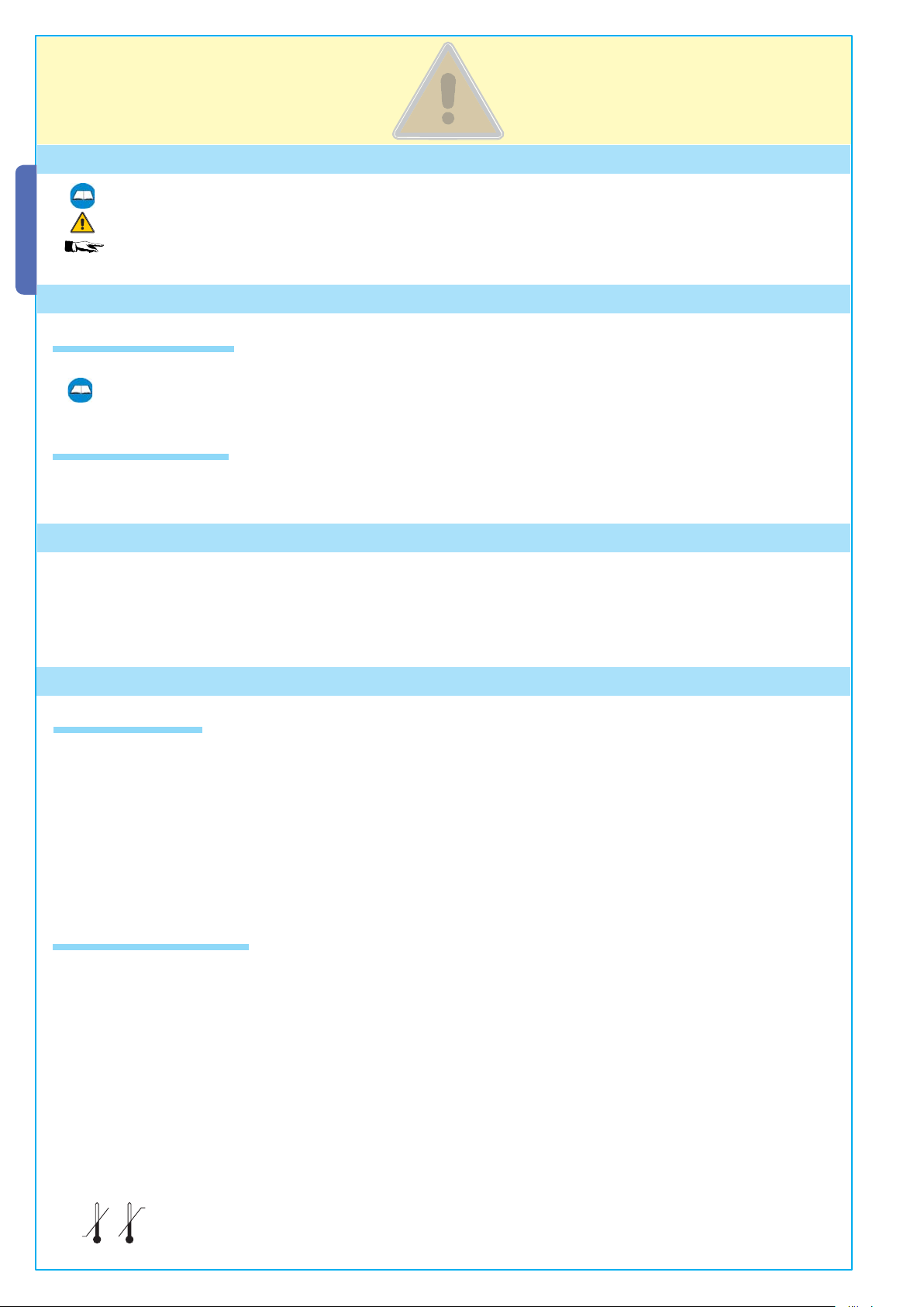
4.3 Dimensions
67
60
160
405 330
5 Installation
Installation must be carried out by expert qualified personnel and in full compliance with current regulations.
5.1 Preliminary checks
Before installing, do the following:
• Make sure you have a suitable omnipolar cut-off device with contacts more than 3 mm apart, and independent (sectioned off)
power supply;
• Make sure you have suitable tubing and conduits for the electrical cables to pass through and be protected against mechanical
damage;
• Fit tubing to drain away any water leaks which may cause oxidation;
• Make sure that any connections inside the case (that provide continuance to the protective circuit) be fitted with extra
insulation as compared to the other conductive parts inside;
• Make sure the structure of the gate is sturdy, the hinges work and that there is no friction between moving and non-moving
parts;
• Make sure there is a mechanical stop for opening and closing.
ENGLISH
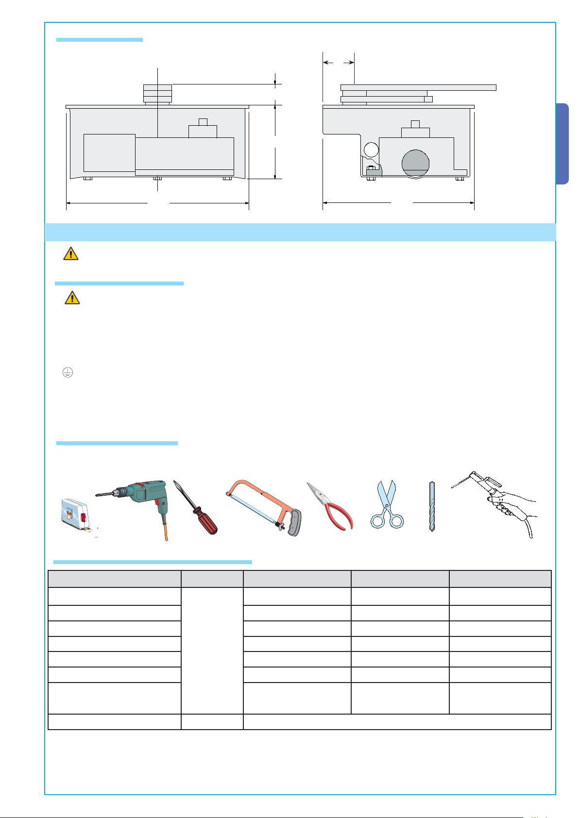
5.2 Tools and materials
Make sure you have all the tools and materials you will need for the installation at hand to work in total safety and compliance with the current standards and regulations. The following figure illustrates the minimum equipment needed by the
installer.
5.3 Cable list and minimum thickness
Connections Type of cable Length of cable 1 < 10 m Leng. cable 10 < 20 m Leng. cable 20 < 30 m
Control panel power supply 230V
3G 1,5 mm
Motor power supply 24V 3 x 1 mm
Flashing light 2 x 0,5 mm
Photocell transmitters 2 x 0,5 mm
The data and information shown in this manual may be changed by CAME cancelli automatici s.p.a. at any time without prior warning.
Photocell receivers 4 x 0,5 mm
Accessories power supply 2 x 0,5 mm
FROR CEI
20-22
CEI EN
50267-2-1
Control and safety devices 2 x 0,5 mm
2
2
2
2
2
2
2
3G 2,5 mm
3 x 1,5 mm
2 x 1 mm
2 x 0.5 mm
4 x 0,5 mm
2 x 0,5 mm
2 x 0,5 mm
2
2
2
2
2
2
2
3G 4 mm
3 x 2,5 mm
2 x 1,5 mm
2 x 0,5 mm
4 x 0,5 mm
2 x 1 mm
2 x 0,5 mm
2
2
2
2
2
2
2
Antenna connection RG58 max. 10 m
N.B.: If the cable length differs from that specified in the table, then you must determine the proper cable diameter in the basis of
the actual power draw by the connected devices and depending on the standards specified in CEI EN 60204-1.
For connections that require several, sequential loads, the sizes given on the table must be re-evaluated based on actual power
draw and distances. When connecting products that are not described in this manual, please refer to the instructions that come
with said products.
3
Page 4

5.4 Standard installation
10
ENGLISH
9
1
RX
4x1
1) FROG unit
2) Control panel
3) Safety photocells
4) Radio receiver
5) Key-switch selector
3
TX
4x1,5
2x1
8
1
6
5
2
3x1
RG58
2x1,5
RX
5x1
4x1
3x1,5
230V
6) Antenna
7)
Command push-buthon panel
8) Flashing light
9) Photocell column
4
10) Shunt box
11) Transmitter
7
TX
3
9
11
4x1,5
10
2x1
5.5 Assembly diagram
Fig.2
67
3
160
100 60
67
5.6 Installing the unit
- Check the effi ciency of both moving and non-moving parts on the structure that will be supporting the operator;
- Determine, depending on the type of supporting structure and desired opening, the exact position of the motor assembly by
following the standard applications shown;
- Set up a closing end stop and an opening end stop (fi g. 4, p. 5)
- Dig, depending on the size of the assembly, a foundation pit in the chosen spot (Fig. 3);
- Prepare a drainage system in the foundation, to drain away any water leaks which may cause oxidation (fi g 3 – part.1);
- The foundation box makes for quick and easy setting up of the assembly. Place it inside the pit with the pin aligned to the upper
hinge (Fig. 3 – part. 2), sink it into the cement (Fig. 3 – part. 3) making sure it is perfectly levelled and that the upper edge is 3mm
above ground level (Fig. 3 part. 4);
- Plan for the route of the electrical cables according to the command
Fig.3
and safety instructions using the apposite hole on the box (Fig. 3
– part. 5);
- Grease the rotation pins of the foundation box and the gate attachment lever; the hinge and pin lever must be aligned;
- Position the gate leaf between the upper hinge and the pin lever;
the hinge and pin lever must be aligned;
- Secure the pin lever to the gate leaf, by welding spots 3 to 4 cm
apart along the contact surface. Avoid any welding near the threaded
screws (Fig. 3 – Part. 6).
The data and information shown in this manual may be changed by CAME cancelli automatici s.p.a. at any time without prior warning.
4
Page 5

- Screw the M10 x 100 (A) and the M10 (B) bolt onto the gearmotor arm as shown in fi g. 4-1 (RIGHT HAND installation) and fi g.
4-2 N(LEFT HA D installation);
- Affi x the gearmotor to the foundation box using the threaded pins and securing it using the provided bolts and washers;
- insert the (C ) transmission lever between the motor arm and the box lever and electronically shut the gate against the closing
end stop. Adjust screw (A) until it touches the (C) transmission lever.
- When testing, adjust the screw so as to allow proper closing pressure of the gate leaf and allow its re-hooking during the mechanism’s release procedure.
- Once adjustment is complete, secure the (B) nut.
ENGLISH
Fig.4
SX
DX
Fig.4-1
SX
C
A
B
C
Fig.4-2
DX
A
B
5.7 Manual release
- In emergencies (i.e. power outages) the release mechanisms allow the gate to hook back up when closing.
- You may choose among three different release models: model A4366 with customised key (Fig. 5-A), model A4365 with tri-lobed
key and model A4364 with lever key (Fig. 5-B). We suggest greasing the release’s hook-up key (Fig. 5-B – part. 3); Consult the
documentation pertinent to the relative items for the release procedure.
N. B.: release operations are to be carried out during emergency procedures and with the power disconnected.
Fig. 5
Fig. 5-A
Fig. 5-B
3
A4366
A4365
A4364
6 Connecting to the control panel
The data and information shown in this manual may be changed by CAME cancelli automatici s.p.a. at any time without prior warning.
- We suggest making the gearmotor cable connections in shunt boxes;
- For further information concerning the functions, see the technical documentation for the (ZA3, ZA4, ZA5 or ZM2) control pa-
nels.
5
Page 6

7 Safety instructions
Important safety instructions
This product must only be employed for its originally intended use. Any other use is wrong and potentially dangerous. The
manufacturer cannot be held liable for any damages resulting from wrongful, erroneous or negligent uses.
Avoid working close to the hinges or other moving mechanical parts. Stay out of the opening/closing arc when operator is in
motion. Do not exercise force against the motion of the operator as this could result in potentially dangerous situations.
ENGLISH
Do not allow children to play or loiter within the opening/closing arc of the operator.
Keep remote controls and any other command device out the reach of children, to prevent operator from being activated by
accident.In the event of anomalous behaviour, stop using the operator immediately.
Danger of crushing hands
Danger of crushing feet
Danger! High voltage
No transit during operation
The data and information shown in this manual may be changed by CAME cancelli automatici s.p.a. at any time without prior warning.
6
Page 7

8 Maintenance
8.1 Periodic maintenance
Periodic maintenance to be carried out by the end-user is as follows: wipe clean the glass surface of the photocells;
check that the safety devices work properly; remove any obstructions.
We suggest checking the state of lubrication and tightness of the anchoring screws on the operator.
To check the efficiency of the safety devices, move an object in front of the photocells when gate is closing. If the operator
inverts the motion or stops, the photocells are working properly.
This is the only maintenance procedure to be carried out with the power source connected.
Before performing any maintenance procedures, cut off the main power, to prevent possible accidents due to gate movement.
To clean the photocells use a water dampened cloth. Do not use solvents or other chemical products which may ruin the devices.
In the event of any strange vibrations or squeaking, lubricate the joints with grease, as shown in the diagram.
ENGLISH
Make sure there are no plants within the photocell’s beam, and that the gate motion is free of any obstacles.
8.2 Trouble shooting
MALFUNCTIONS POSSIBLE CAUSES CHECK AND REMEDIES
The gate will not open
The data and information shown in this manual may be changed by CAME cancelli automatici s.p.a. at any time without prior warning.
nor close
The gate opens but will
not close
The flasher does not
work
• There is no power
• The gearmotor is released
• The remote control’s batteries are run down
• The transmitter is broken
• The stop button is either stuck or broken
• The opening/closing button or the key selector are stuck
• The photocells are engaged • Check that photocells are clean
• The bulb is burnt • Call assistance
• Check that the power is up
• Call assistance
• Replace batteries
• Call assistance
• Call assistance
• Call assistance
and in good working order
• Call assistance
7
Page 8

Periodic maintenance log (for end-user) (every 6 moths)
Date Notes Segnature
ENGLISH
8.3 Extra-ordinary maintenance
The following table serves to note down any extraordinary maintenance, repairs or improvements performed by specialised firms.
N.B.: Any extraordinary maintenance must be performed by specialised technicians.
Extra-ordinary maintenance log
Installer’s stamp Operator name
Date of job
Tec hnician’s segnatur e
Requester’s segnature
Job performed_____________________________________________________________________________________
________________________________________________________________________________________________
Installer’s stamp Operator name
Date of job
Tec hnician’s segnatur e
Requester’s segnature
Job performed_____________________________________________________________________________________
________________________________________________________________________________________________
The data and information shown in this manual may be changed by CAME cancelli automatici s.p.a. at any time without prior warning.
Installer’s stamp Operator name
Date of job
Tec hnician’s segnatur e
Requester’s segnature
Job performed_____________________________________________________________________________________
________________________________________________________________________________________________
8
Page 9

Installer’s stamp Operator name
Date of job
Tec hnician’s segnatur e
Requester’s segnature
Job performed_____________________________________________________________________________________
________________________________________________________________________________________________
Installer’s stamp Operator name
Date of job
Tec hnician’s segnatur e
Requester’s segnature
Job performed_____________________________________________________________________________________
________________________________________________________________________________________________
9 Demolition and disposal
In its premises, CAME cancelli automatici s.p.a. implements an Environmental Management System certified in compliance with the UNI EN ISO 14001 standard to ensure environmental protection.
Please continue our efforts to protect the environment—which CAME considers one of the cardinal elements in the developmentof its operational and market strategies—simply by observing brief recommendations as regards disposal:
ENGLISH
DISPOSAL OF PACKAGING
The packaging components (cardboard, plastic, etc.) are all classifiable as solid urban waste products and may be disposed of
easily, keeping in mind recycling possibilities.
Prior to disposal, it is always advisable to check specific regulations in force in the place of installation.
PLEASE DISPOSE OF PROPERLY!
PRODUCT DISPOSAL
Our products are made up of various types of materials. Most of them (aluminium, plastics, iron, electrical wires, etc.) may
be disposed of in normal garbage collection bins and can be recycled by disposing of in specific recyclable material collection
bins and disposal in authorized centres.
Other components (electrical boards, remote control batteries, etc.), however, may contain polluting substances.
They should therefore be removed and given to qualified service companies for proper disposal.
Prior to disposal, it is always advisable to check specific regulations in force in the place of disposal.
PLEASE DISPOSE OF PROPERLY!
10 Maker’s statement
MANUFACTURER’S DECLARATION OF CONFORMITY
CAME Cancelli Automatici S.p.A.
via Martiri della Libertà, 15
31030 Dosson di Casier - Treviso - ITALY
tel (+39) 0422 4940 - fax (+39) 0422 4941
internet: www.came.it - e-mail: info@came.it
The data and information shown in this manual may be changed by CAME cancelli automatici s.p.a. at any time without prior warning.
Declares under its own responsibility that the equipments for automatic garage doors and
gates listed below:
FROG-A
… comply with the National Law related to the following European Directives and to the
applicable parts of the following Standards.
98/37/CE - 98/79/CE M
98/336/CEE - 92/31/CEE ELECTROMAGNETIC COMPATIBILITY DIRECTIVE
73/23/CEE - 93/68/CE LOW VOLTAGE DIRECTIVE
89/106/CEE CONSTRUCTION PRODUCTS DIRECTIVE
EN 13241-1 EN 12635 EN 61000-6-2
EN 12453 EN 12978 EN 61000-6-3
EN 12445 EN 60335-1 EN 60204-1
ACHINERY DIRECTIVE
Pursuant to annex II B of the Machinery Directive 98/37/EC
Do not use the equipment specifi ed here above, before completing the full installation
In full compliance with the Machinery Directive 98/37/EC
IMPORTANT WARNING!
MANAGING DIRECTOR
Mr. Andrea Menuzzo
Reference code to request a true copy of the original: DDF B EN A001D
9
Page 10

CAME UNITED KINGDOM LTD
UNIT 3, ORCHARD BUSINESS PARK TOWN
STREET, SANDIACRE
NOTTINGHAM - NG10 5BP - U.K.
Tel 0044 115 9210430
Fax 0044 115 9210431
Cod. 119AS45 v30 01/07 © CAME cancelli automatici s.p.a.
 Loading...