

Page 1

10
11
7
2
–
–
+
001DC011AC
001DC002AC
001DC011AC
001DC02EARY
001CS1PLCO
INSTALLATION MANUAL
001CK0009
001CK0012 FR-001CK0013 FR
EN
English
FA00959-EN
AUDIO ENTRY KIT
Page 2
Ø60
503
a
B
A
C
Page 2 - Manual FA00959-EN - vers. 1
- 10/2017- © Came S.p.A. - The contents of this manual may be changed, at any time, and without notice.
General Notes
• Read the instructions carefully before beginning the installation and carry
out the actions as specied by the manufacturer.
• The installation, programming, commissioning and maintenance of the
product must only be carried out by qualied technicians, properly trained
in compliance with the regulations in force, including health and safety
measures and the disposal of packaging.
• The installer must ensure that the information for the user, where there is
any, is provided and delivered.
• Before carrying out any cleaning or maintenance operation, disconnect the
devices from the power supply.
• The equipment must only be used for the purpose for which it was
expressly designed.
• The manufacturer declines all liability for any damage as a result of improper, incorrect or unreasonable use.
eventuali danni derivanti da usi impropri, erronei ed irragionevoli.
This product complies with the relevant directives in force.
Decommissioning and disposal. Dispose of the packaging and the device
at the end of its life cycle responsibly, in compliance with the laws in force
in the country where the product is used. The recyclable components are
marked with a symbol and the material's ID marker.
The data and information shown in this manual are to be considered as
subject to change at any time and without the need for any advance warning.
Measurements, unless otherwise indicated, are in millimetres.
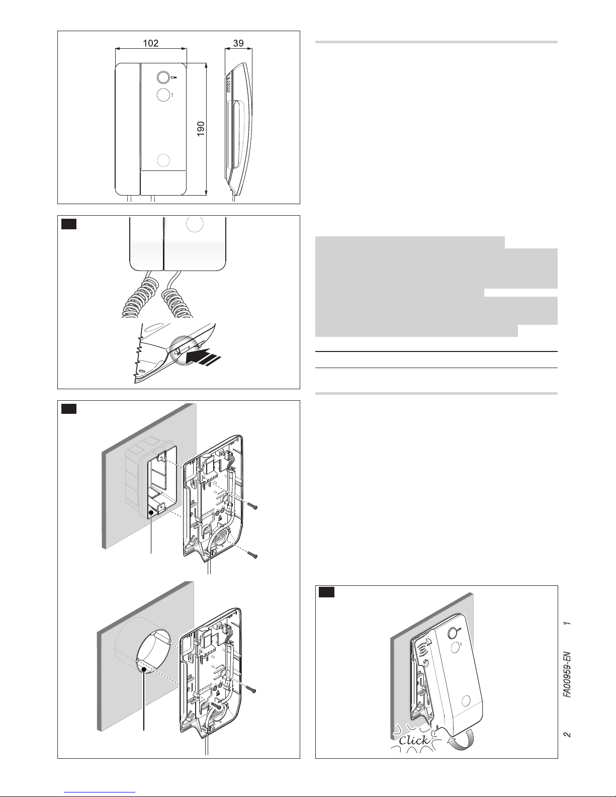
001DC02EARY
Installation
Open the unit by pressing the lever on the back A.
Remove the casing from the back of the unit.
Attach the back of the unit to a wall box using the screws provided Ba
B. The box must be installed at a suitable height for the user. Do not
over-tighten the screws.
Once connections have been completed, re-assemble the casing to the
back of the unit C.
Page 3
D
– +
– +
B
B
AL
M1
SW3
SW3
M1
a
Page 3 - Manual FA00959-EN - vers. 1
- 10/2017- © Came S.p.A. - The contents of this manual may be changed, at any time, and without notice.
Technical features
Type
001DC02EARY
Power supply from BUS [V DC]
15÷20
Consumption max [mA] 30
Consumption in stand by [mA] <0,5
Single LED consumption [mA]
1
Storage temperature [°C] -25 ÷ +70
Operating temperature [°C] +5 ÷ +40
IP Rating [IP]
30
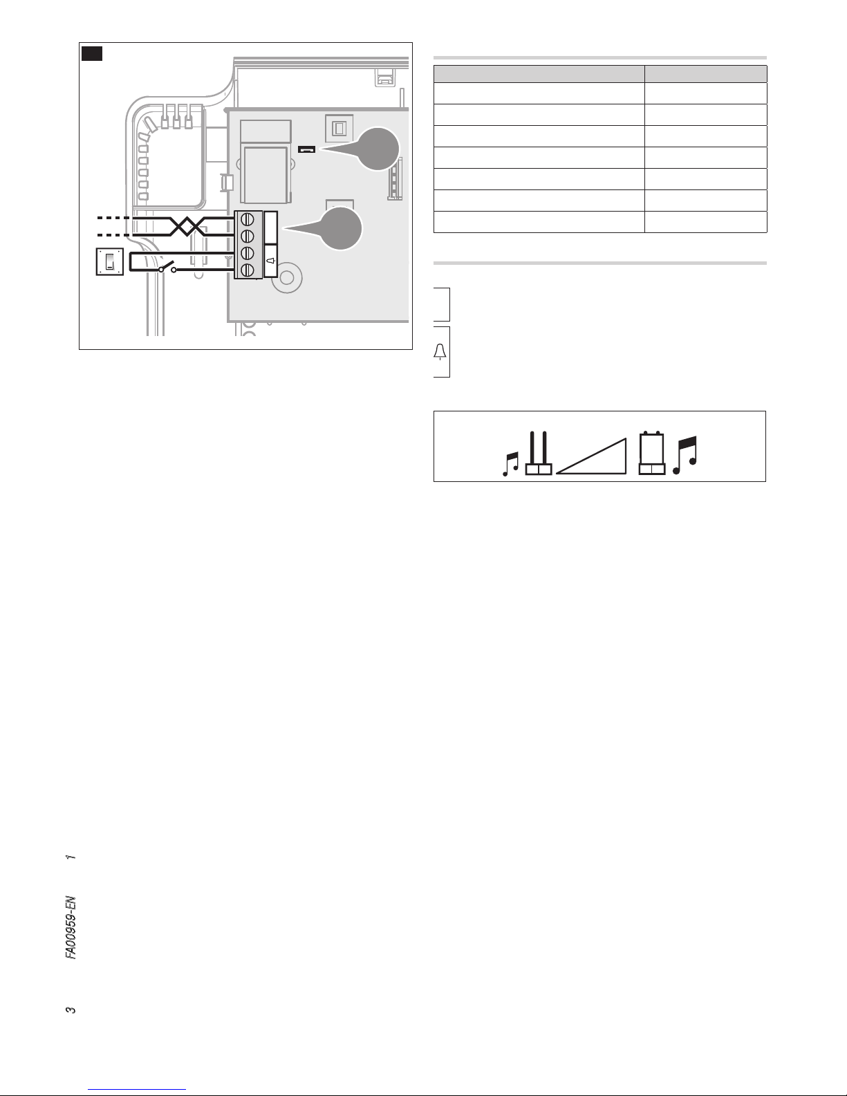
Features D
Terminal board a
B BUS line input
+
Doorbell
–
Call attenuated
SW3 SW3
Page 4

... beep!
A x5
... beep!
A x5
... beep!
A x5
... beep!
A x5
... beep!
A x5
... beep!
A x5
... beep!
A x5
... beep!
A x5
... beep!
A x5
a
g
c
f
e
h
i
Page 4 - Manual FA00959-EN - vers. 1
- 10/2017- © Came S.p.A. - The contents of this manual may be changed, at any time, and without notice.
4- Programming the number of rings
Press button as many times as you want the call to ring (from 1 to 6 rings) h.
Three seconds after the button is last pressed, the selected call is played back with the
chosen number of rings.
To exit programming, hang up the handset i.
☞ See the entry panel documentation for call programming.
3- Programming the melody associated with a call from the floor
To listen to the melodies in sequence, press button e.
To select the melody and exit programming, hang up the handset f.
To select the melody and continue with programming, press button g.
2- Programming the melody associated with a call from the entry panel
To listen to the melodies in sequence, press the button .
To select the melody and exit programming, hang up the handset c.
To select the melody and continue with programming, press the button .
1-Entering programming mode
Lift up the handset and press button A 5 times in 5 seconds.
A short beep conrms that you have entered programming mode a.
Melody setting
☞ All the programming stages described below must be carried out in sequence:
Page 5
A
43,5
45
7,5
57
70
106
A
43,5
45
7,5
57
M2M1
+–
a
Page 5 - Manual FA00959-EN - vers. 1
- 10/2017- © Came S.p.A. - The contents of this manual may be changed, at any time, and without notice.
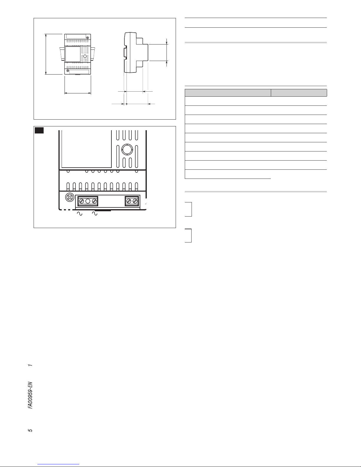
001DC002AC
Installation
The power supplier must ALWAYS be installed horizontally. The device can be
installed on a DIN rail (EN 50022) in an appropriate electric panel.
NOTE. Proper ventilation is required if the power supplier is installed in a
metal container.
Technical features
Type
001DC002AC
Power supply [V AC] 230
Max current demand [A AC]
0,2
Max energy dissipation [W] 10
Nominal power supply [V DC] 18
Nominal current demand [A DC]
1 for 1’
Nominal current demand [A DC] 0.5 for 3’
Storage temperature [°C] -25 ÷ +70
Operating temperature [°C]
0 ÷ +35
IP Rating [IP] 30
Features A
Terminal board a
~
Mains
~
Terminal board
–
+
Power supply 18 VDC (*)
(*) The appliance is electronically protected against overloads and short
circuits.
Page 6

48,5 mm
21 mm
60 mm
85,5 mm
69,5 mm
A
10
11
7
2
–
–
+
001DC011AC
a
Page 6 - Manual FA00959-EN - vers. 1
- 10/2017- © Came S.p.A. - The contents of this manual may be changed, at any time, and without notice.
001DC011AC
Device description A
The 001DC011AC AC/DC converter is device designed for the installation
of audio receivers and video receivers coupled with a compatible gate
automatism equipped with an accessory output.
With just 4 wires that connect the gate with the audio receiver/video receiver
kit, the device not only supplies the kit but it also allows you to operate the
gate. Command 2-7 is executed by a clean contact (relay).
Technical features
Type 001DC011AC
Minimum input voltage (V AC) 20
Maximum input voltage (V AC) 25
Output voltage (V DC) 18
Output current (A) 1
Maximum operating relative humidity without
condensation
95
Storage temperature (°C) -25 ÷ +70
Operating temperature (°C) -15 ÷ +50
Features of terminals 2 - 7
Control voltage: 12V - 12.5 mA
Maximum switching voltage: 50 V AC or 75 V DC
Maximum switching power: 60VA - 24W
Function of terminals
–
18V DC supply output
+
2
Opening command output towards gate
7
10
Power supply input 20÷25V AC
11
–
Opening command input from entry panel
Page 7

A
B C
135
99
30
3.5
6.5
207
135
3.5
6.5
D
A
B
a
E
Page 7 - Manual FA00959-EN - vers. 1
- 10/2017- © Came S.p.A. - The contents of this manual may be changed, at any time, and without notice.
001CS1PLCO
Wall mounting
With the allen wrench unscrew the blocking screws and remove the plate
A. Fix the given plugs and screw the entry panel B at the desired height.
Run the hose with the system conductors B.
Extract the plastic terminal cover and wire the connections C.
Once all the connections have been made, re-insert the terminal covers.
For the installation of the accessories refer to the chapter “Button module installation”. Perform the programming and adjustment operations of the entry
panel as described to the chapter “Programming”. Install the front plate A.
Recessed Installation (optional)
Install the recessed box at the desired height, but in advance, run the hose
with the system conductors through one of the breaking points D a.
During installation of the recessed box it is possible to avoid any deformation
by using the provided spacer D . With the allen wrench unscrew the
blocking screws and remove the entry panel plate A. Introduce the cable
connections in the special hole B and x the entry panel on the frame E;
extract the plastic terminal cover and wire the connections C.
Once the connections have been made and re-insert the terminal covers.
For the installation of the accessories refer to the chapter “Button module
installation”.
Perform the programming and adjustment operations of the entry panel as
described to the chapter “Programming”. Install the front plate A.
Page 8

G H
F
1
2
I
a
c
Page 8 - Manual FA00959-EN - vers. 1
- 10/2017- © Came S.p.A. - The contents of this manual may be changed, at any time, and without notice.
Personalized labels, dimensions
53x33x0,3 mm53x13x0,3 mm
Accessories I
001DC00EGMA11 single button a,
001DC00PLACO01 Wall roof ,
Recessed box 001DC00PLCO03 c,
Recessed frame 001DC00PLACO02 .
Technical features
Tipo 001CS1PLCO
Power supply [V AC] 16-18
Consumption [mA] 250
Consumption in stand by [mA] 100
Storage temperature [°C] -25 ÷ +70
Operating temperature [°C) -15 ÷ +50
IP Rating [IP] 54
Button module installation
Insert the button module as highlighted F paying special attention to the
top to bottom orientation H.
Remove the glass and write the user names G, paying special attention to
the orientation of the glass H.
Page 9

M1
BOUT
M2
SW3
PROG
RESET
LED PROG
a
c
e
J
Page 9 - Manual FA00959-EN - vers. 1
- 10/2017- © Came S.p.A. - The contents of this manual may be changed, at any time, and without notice.
Features J
Terminal board a
BOUT
Riser
+
Power supply 16-18 VDC
–
Terminal board
–
Earth
Door lock release button (NA)
Solenoid lock
12 V 1 A max
–
PROG key c and PROG LED
Programming key and LED (see 'Programming' paragraph).
The PROG LED can take on the following states:
O
On
Slow ashing
Quick ashing
Adjustments e
loudspeaker audio
microphone audio
Solenoid lock 1-10 s. (default 1 s)
Page 10

M1
BOUT
M2
SW3
PROG
RESET
PROG
M2M1
+–
VLS/300
B
B
–
NO
C
–
+
001DC002AC
001DC005AC
K
SW3
PROG
RESET
PROG
PROG
RESET
PROG
>3’’
<6’’
a
c
e
f
g
beep
c A
SW3
PROG
RESET
PROG
Page 10 - Manual FA00959-EN - vers. 1
- 10/2017- © Came S.p.A. - The contents of this manual may be changed, at any time, and without notice.
Programming the call keys. Lift the receiver (if present) of the extension that you want to programme
e then press the door lock release and AUX2 f buttons. On the entry panel, press the call
key to associate with the internal extension g: an acoustic signal will conrm that the setting was
stored. Hang up the receiver again, if necessary h and continue, repeating the same operations for
the other extensions.
Entering Programming Mode. Press the PROG a key for at least 3 seconds and then release it
(within 6 seconds), as soon as the LED PROG lights up and the key back lighting ashes as illustrated
in gure . Failure of the PROG LED to light up, indicates a malfunction. Check the connections and
re-access the programming mode.
Programming of the Key Type. Press the rst key of the entry panel in the position indicated c/
cA until the backlighting LED stops ashing and remains lit.
Programming
The kit is pre-configured to manage a single call originating from a single entry panel. One or more receivers answering the same call can be
added, by following the below “Call button programming” procedure.
Initial programming
001DC005AC
001DC002AC
Connection example K
Page 11

PROG
RESET
PROG
i
g
h
f
i
c
e
beep
SW3
PROG
RESET
PROG
SW3
PROG
RESET
PROG
SW3
PROG
RESET
PROG
<1’’
<1’’
M1
PROGM1PROG
SW3
PROG
RESET
PROG
>3’’
<6’’
SW3
PROG
RESET
PROG
>3’’
<6’’
a
h
Page 11 - Manual FA00959-EN - vers. 1
- 10/2017- © Came S.p.A. - The contents of this manual may be changed, at any time, and without notice.
Exiting programming. Briey press the PROG key g: the PROG LED o. NOTE. If no action is performed, the procedure will automatically end after 30 minutes.
Programming key type. At the “Programming Call Buttons” stage, press the PROG h key for at least 3 seconds and then release it (within 6 seconds), as
soon as the LED PROG lights up and the key back lighting ashes as illustrated in gure i, entering “Programming Button Types/Combinations” as part
of the procedure.
Press the rst key of the entry panel in the position indicated until the backlighting LED stops ashing and remains lit.
At the end, exit programming, briey press the PROG key g: the PROG LED will turn o. If no action is performed, the procedure will end automatically
after 30 minutes.
Programming the call keys. Lift the receiver (if present) of the extension that you want to programme
c then press the door lock release and AUX2 buttons. On the entry panel, press the call
key to be associated with the internal extension e: an acoustic signal will conrm that the setting
was stored. Hang up the receiver again, if necessary f and continue, repeating the same operations
for the other extensions.
Entering Programming Mode. Press the PROG a key for at least 3 seconds and then release it (within
6 seconds) as soon as the LED PROG light ashes and the key back lighting lights up as illustrated in
gure . Failure of the PROG LED to light up, indicates a malfunction. Check the connections and
re-access the programming mode.
Reprogramming procedure
Exiting programming. Briey press the PROG
key i: the PROG LED o. NOTE. If no action is
performed, the procedure will automatically end
after 30 minutes.
Page 12

a
a
c
001CS1PLCO
+
BOUT
-
-
-
M1
+
–
M2
M2
001DC002AC
A
SW3
B
–
+
001DC02EARY
M1
001CS1PLCO
+
BOUT
-
-
-
M2
+
–
M2
M1
001DC002AC
A
001DC02EARY
M1
SW3
B
–
+
001DC02EARY
M1
SW3
B
–
+
001DC02EARY
M1
SW3
B
–
+
001DC002AC
2
2
2
2
001DC002AC
2
001DC002AC
2
001DC011AC
4
4
10
11
7
2
–
–
+
001DC011AC
CAME GATE
2
2
001DC002AC
2
001DC002AC
2
2
2
001DC011AC
4
4
10
11
7
2
–
–
+
001DC011AC
CAME GATE
2
001DC002AC
2
2
2
001DC011AC
4
4
10
11
7
2
–
–
+
001DC011AC
CAME GATE
2
2
001DC011AC
4
4
10
11
7
2
–
–
+
001DC011AC
CAME GATE
Page 12 - Manual FA00959-EN - vers. 1
- 10/2017- © Came S.p.A. - The contents of this manual may be changed, at any time, and without notice.
Connection examples
Page 13

c
001CS1PLCO
1
2
+
BOUT
-
M1
001DC002AC
A
+
–
M2
-
-
M2
SW3
B
–
+
001DC02EARY
M1
1
SW3
B
–
+
001DC02EARY
M1
001DC02EARY
M1
SW3
B
–
+
2
001DC02EARY
M1
SW3
B
–
+
1
2
+
BOUT
-
M1
-
-
M2
+
-
-
11
10
7
2
2
7
10
11
001DC02EARY
SW3
M1
B
–
+
001CS1PLC0001DC011AC
CAME GATE
10
11
7
2
–
–
+
001DC011AC
Page 13 - Manual FA00959-EN - vers. 1
- 10/2017- © Came S.p.A. - The contents of this manual may be changed, at any time, and without notice.
Page 14

Le
La Lb
Lc Ld
001CS1PLCO
001DC002AC
001DC011AC
Page 14 - Manual FA00959-EN - vers. 1
- 10/2017- © Came S.p.A. - The contents of this manual may be changed, at any time, and without notice.
Distances
VCM/1D VCM/2D UTP/CAT 5 2x2,5mm
2
La, Lb, Lc, Ld ≤250 m – ≤250 m –
Le ≤25 m – – ≤60 m
La(Lb, Lc, Ld)+Le ≤250 m
Distances
Page 15

Page 15 - Manual FA00959-EN - vers. 1
- 10/2017- © Came S.p.A. - The contents of this manual may be changed, at any time, and without notice.
Page 16

CAME S.p.A.
Via Martiri Della Libertà, 15
31030 Dosson di Casier - Treviso - Italy
tel. (+39) 0422 4940 - fax. (+39) 0422 4941
Page 16 - Manual FA00959-EN - vers. 1
- 10/2017- © Came S.p.A. - The contents of this manual may be changed, at any time, and without notice.
 Loading...