

Page 1
Electrified Locks, Relays and Timers
CX-WEC10CK2
Emergency Control Kit
INSTALLATION INSTRUCTIONS
THIS PACKAGE INCLUDES:
1- CM-AF540SO (CM-450R/12, CM-AF501SO combo) 2- CM-AF142SO 1- CM-SE21A
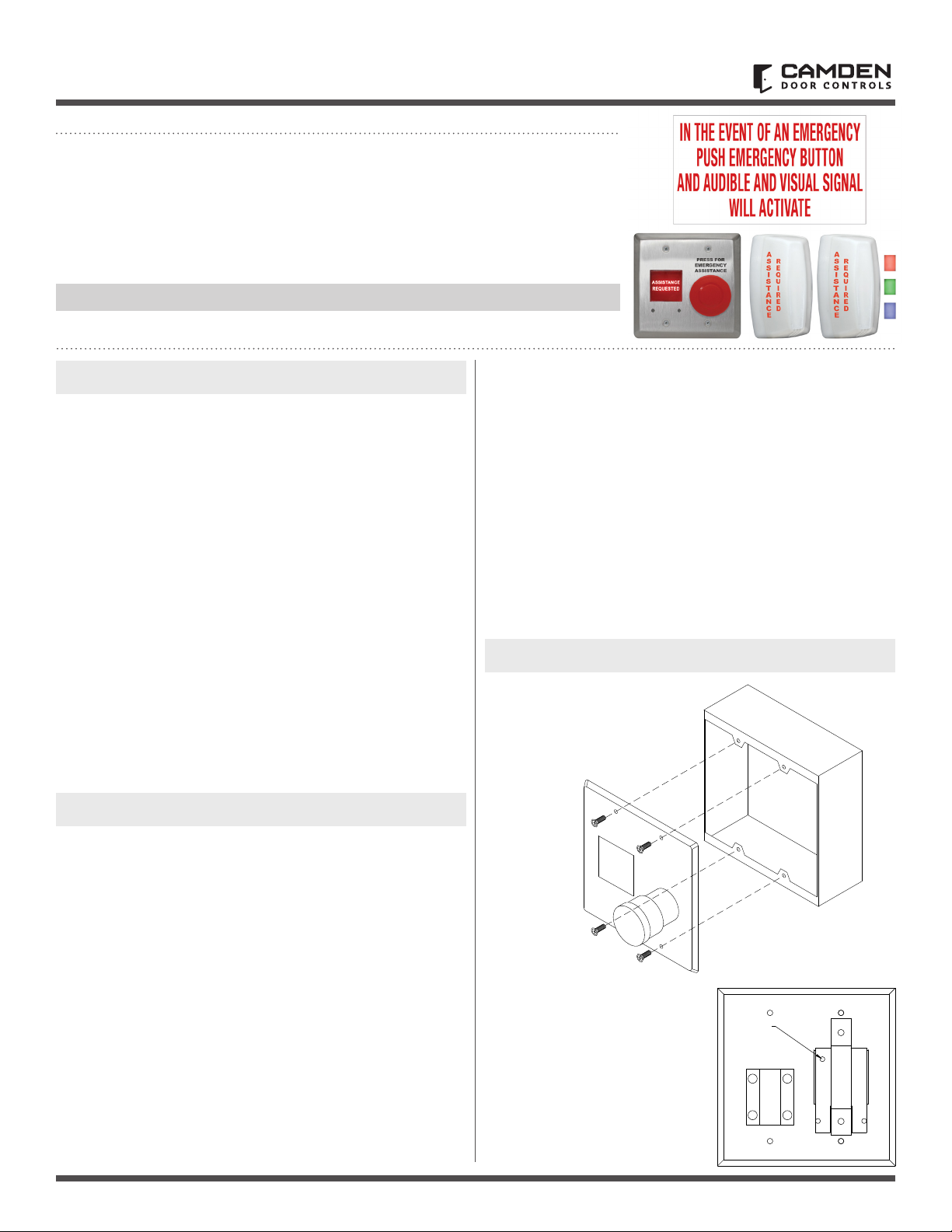
1. DESCRIPTION
The CX-WEC10CK2 Emergency Control Kit allows an individual
to push the “PRESS FOR EMERGENCY ASSISTANCE” button to
signal for help by illuminating two of the “Assistance Required”
annunciators on the outside and the “Assistance Requested”
annunciator on the inside of the location. At the same time,
activating the sounders built into all three annunciators. The
kit includes signage that states in the event of an emergency to
press the button and an audible and visual signal will activate.
The CX-WEC10CK2 kit comes with the inside activation and
annunciator built onto a double gang combination plate making
installations quicker since one back box install is needed rather
that two single gang boxes. The two CM-AF142SO annunciators
offer different color options (Red, Green, Blue and White), an
adjustable ash rate and variable volume control. The two
CM-AF142SO sounders can be placed in such a manner to ensure
adequate notication above the door and in a secondary
location. This will be done if the location is far away, around a
corner or needs to be part of a Nurse of Guard station to alert
staff to a request for assistance has been made.
Note: CX-WEC10CK2 Emergency Call System is OBC Regulation
368/13, Section 3.8.3.12 compliant.
2. OPERATION AT A GLANCE
Wiring the CX-WEC10CK2 Emergency Control Kit
The inside and outside annunciators are wired in parallel to make
them work at the same time when triggered. Take one of the black
wires from the CM-AF540SO and the black wires from each
of the CM-AF142SO’s and tie them to the power supplies VDC
ground (-). Take the remaining black wire from the CM-AF540SO
and one of the Red, Blue or Green wires from each of the CMAF1423SO's (or take all colored wires from the CM-AF142SO's to
make White) and wire to the red mushrooms buttons normally
open contact marked as terminal “4”. Next, wire the terminal
marked as “3” to the positive (+) terminal of the VDC power supply.
Note: Some Door Operators provide excessive voltage levels
above their posted values. Always measure voltages provided
on both the VDC & VAC scales rst before applying power to
any part of the Emergency Control Kit.
3. INSTALLATION
CM-AF540SO
Supplied with a stainless steel
faceplate that can be easily
mounted to a double gang
electrical box.
When the “PRESS FOR EMERGENCY ASSISTANCE” button on the
CM-AF540SO is pushed in, it will change its normally open contact
to a closed contact and activate both outside light and sounders
(CM-AF142S0) to signal for help. The inside light and sounder
(CM-AF540SO) will also be activated giving the individual inside
conrmation that the action has taken place. Once the emergency
has been attended to, the red mushroom button on the
CM-AF540SO can be pulled out to silence and reset the system.
The CM-AF142SO ash rate can be adjusted at the top right of
the circuit board after removing the front dome cover. The
CM-AF142SO volume can be increased or decreased by using
the adjustment screw on the back of the unit.
Power
Both the CM-AF540SO and the CM-AF142SO can be powered
with either 12/24 VAC/VDC.
Note: When the CX-WEC10CK2 is integrated with a Camden
Restroom Control Kit, VDC power must be used to prevent
the door strike from buzzing.
PRESS FOR
EMERGENCY
ASSISTANCE
Volume Adjust
Turn the volume adjust clockwise
to increase the volume and counter
clockwise to decrease the volume.
Turn the volume adjust all the way
counter clockwise to turn the
sounder completely off.
Volume
Adjust
3
4
1
2
Page 1 of 4
Page 2
CX-WEC10CK2 Emergency Door Control Kit
Gasket
3
Lens
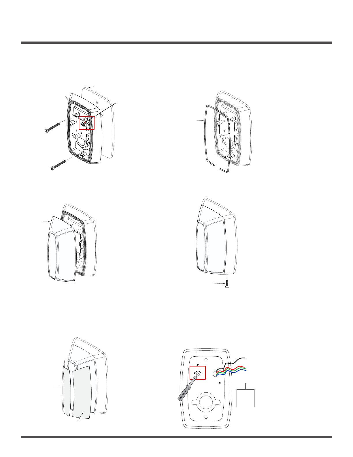
INSTALLATION INSTRUCTIONS
CM-AF142SO Mounts to a standard single gang electrical box.
Step 1
Place the gasket (supplied) between the base unit and the
electrical box. Use the 6-32 screws to fasten the base to the
electrical box.
Base
FLASH RATE:
Increase or decrease
the flash rate by
gently turning the
potentiometer with
a small screwdriver.
1
Step 3
Install the lens by inserting the large bottom tab rst.
The top tabs will snap in place with little effort.
Step 2
Insert the O ring gasket into the small channel in front of the base.
The O ring does not completely close around the base.
You must leave a small opening at the bottom of the base.
O Ring
2
Step 4
Install the Phillips locking screw into the bottom of the base.
Step 5
Apply the labels as required to the lens.
A
S
R
S
Labels
E
I
Q
S
U
T
I
A
R
N
E
C
D
E
5
Labels
Page 2 of 4
Locking Screws
4
Sound Volume Adjust
Using a small Phillips screwdriver, gently turn the volume
adjustment counter clock wise to reduce the volume and
clockwise to increase the volume.
CM-AF142SO
Volume Adjustment
-
+
- Black wire = Common
- Red wire = Red color
- Green wire = Green color
- Blue wire = Blue color
- Blue, Green & Red = White
12-24
AC/DC
Power
Note: The ash rate can be
adjusted at the top right of the
circuit board after removing the
front dome cover. The volume
can be increased or decreased
by using the adjustment screw
on the back of the CM-AF142SO.
Page 3
CX-WEC10CK2 Emergency Door Control Kit
5502 Timberlea Blvd.
Mississauga, ON Canada
L4W 2T7
INSTALLATION INSTRUCTIONS
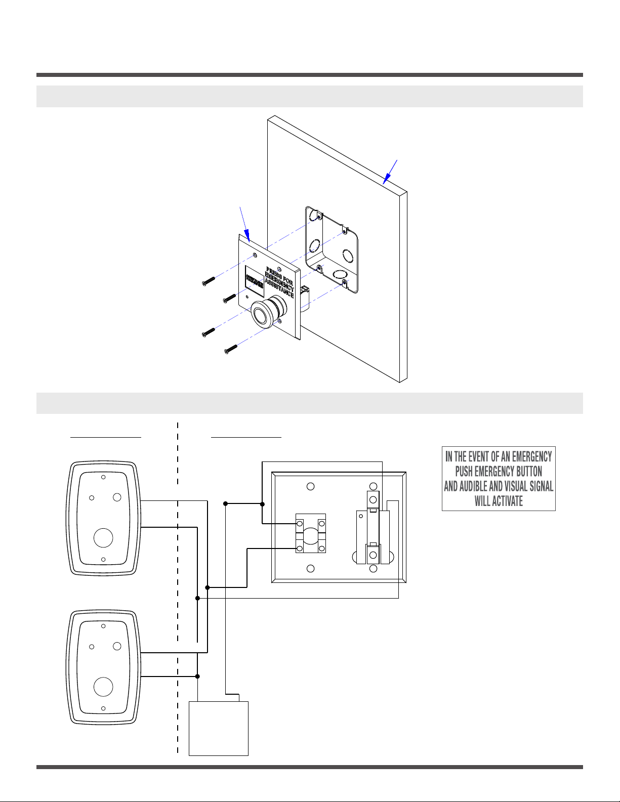
4. DOUBLE GANG CM-AF540SO MOUNTING
CM-AF540SO
Wall
5. WIRING DIAGRAM
CORRIDOR RESTROOM
CM-AF142SO
RED/GREEN/BLUE
BLK
CM-AF142SO
RED/GREEN/BLUE
BLK
N/O
3
4
N/C
1
2
CM-AF540SO
CM-SE21A
Page 3 of 4
-V +V
12/24
VDC/VAC
Power Supply
Camden Power Supply
CX-TRX-2024 Transformer
CX-PS13V3 power regulator
Page 4

ORDERING INFORMATION FOR REPLACEMENT PARTS
Item Part Number Description
CX-WEC10CK2 Emergency Door Control Kit
INSTALLATION INSTRUCTIONS
1
CM-SE21A
English Solid white WEC Sign 6’’ x 10-5/8’’
CM-AF142SO
2
60-31A081
Red Green Blue LED PCB Board 18-30 VAC/VDC
3 60-42K003 Single Gang Dress Plate
4 60-42C027-A Plastic-Dome Lens with English Label ‘’Assistance Required’’
5 60-42C027F-A Plastic-Dome Lens with French Label
6 60-42C027FE-A Plastic-Dome Lens for With French & English Label
7 60-81A010-BK 6"x 2" Clear Lexan .010 Print Black English Label
8 60-81A012 6"x 2" Clear Lexan .010 Print Red English Label
9 60-81A005 6"x 2" Clear Lexan .010 Print Red French Label
10 60-81A004 6"x 2" Clear Lexan .010 Print Red Bilingual Label
CM-AF142SO Parts Kit
6-32 x 3/4 Flat Head Phillips Zinc Plated Screw (2 pcs)
#6 x 3/4" Steel Pan Head Phillips Zinc Screw (2 pcs)
5/16’’ Phillips Rounded Head Screws (1 piece)
11 60-34B089
Yellow/Grey Plastic Anchors 3/16" (2 pcs)
Expanded Green PVC Anchors 10-24 Screw (2 pcs)
Grey Plastic Wire Nut c/w Spring (4 pcs)
Cut Cord (EPDM Durometer Cord CM-AF141SO) (1 piece)
CM-AF540SO
12 60-66C000 Normally Open Contact Block
13 60-66C001 Normally Close Contact Block
14 60-66C002 Normally Open & Normally Close Contact Block
CM-AF540SO Parts Kit
6-32 x 3/4 Phillips Oval Head Stainless Steel Screw (4 pcs)
15 60-34B083
Snake Eye Tamper Proof Screw 6-32 x 3/4" (4 pcs)
Key for Tamper Proof Screws (Snake Eye) (1 pc)
Grey Plastic Wire Nut C/W Spring (2 pcs)
Opening New Doors to
Innovation, Quality and Support!
Call: 1.877.226.3369 / 905.366.3377
Visit: www.camdencontrols.com
File: CX-WEC10CK2 Manual.indd
Rev.: April 29, 2020
Part No.: 40-82A015
Page 4 of 4
 Loading...