

Page 1
CX-ED1259-L
‘RIM’ Electric Strike
Installation Instructions
This Package Includes:
1- 4 PIN power connector
1- 3 PIN door status
connector
4- Wire nuts
2- M5 x self tapping screws
4- M6 x 30 screws
2- M5 x 25 screws
spacers
4- M2.5 x 4 screws
1- MOV
1- Cover plate
1. Description
Camden CX-ED1259-L Grade 1 RIM strike for pullman
latches offer the very best strike quality and performance.
The strike design delivers unparalleled application exibility,
with eld selectable voltage, fail safe/fail secure operation
and mechanical adjustment of the strike body.
2. Specifications
Voltage
Current Draw
12/24V AC/DC
280mA@12V DC
140mA@24V DC
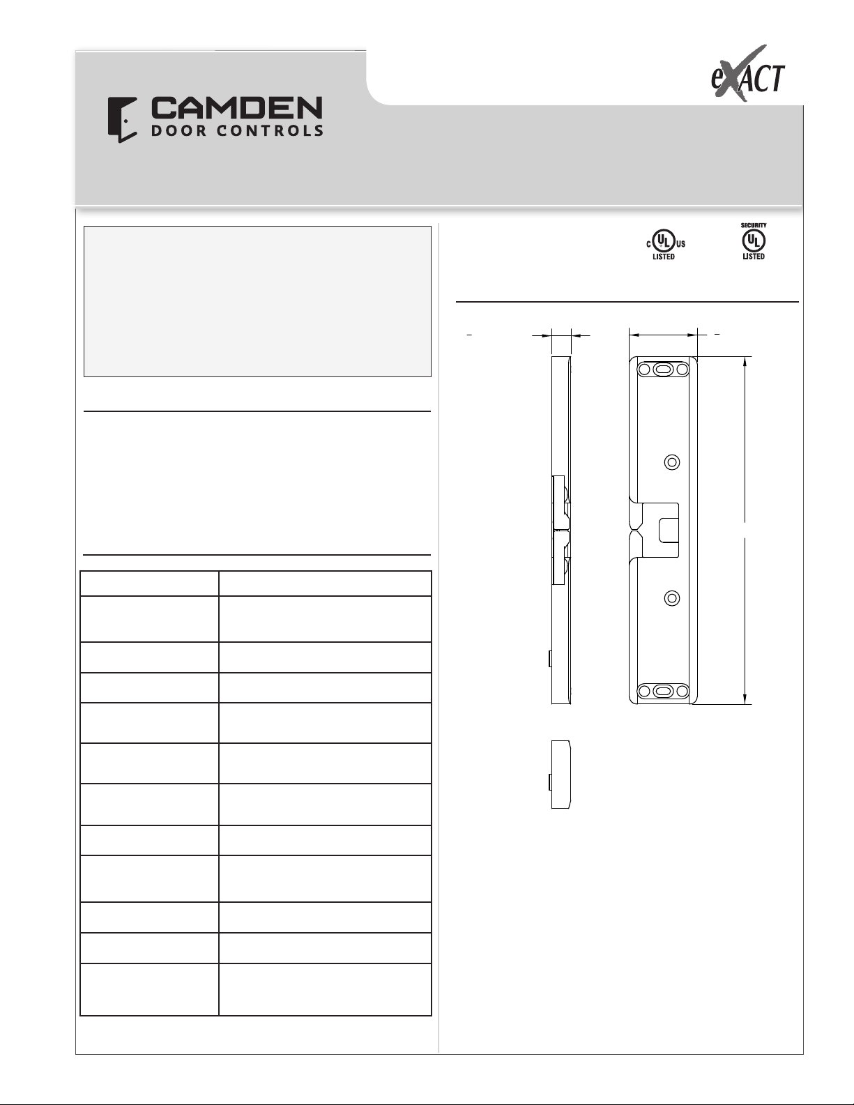
3. Dimensions
1
" [12.7 mm]
2
UL10C/
CAN4-S104,
3hr. Fire rating
3
1
4
9" [230.0 mm]
" [45.0 mm]
UL 1034
Burglary
Static Strength
Dynamic Strength
Endurance
Fire Rating
Mode
Mech. Adjustment
Operation
Duty
Latch Bolt Monitor
Dimensions (Body)
1,500 Lbs.
70 Ft-Lbs.
1,000,000 Cycles (Factory Tested)
250,000 Cycles (UL Verified)
UL 10C/CAN4-S104
3 hrs. (Fail Secure Only)
Field Selectable
Fail Safe/Fail Secure
Strike Body/Faceplate
AC-Buzz
DC-Silent
Continuous
SPDT, 100mA @ 24V DC
9” H x 1 3/4” W x 1/2” D
(230mm x 45mm x 12.7mm)
Page 1 of 3
Page 2
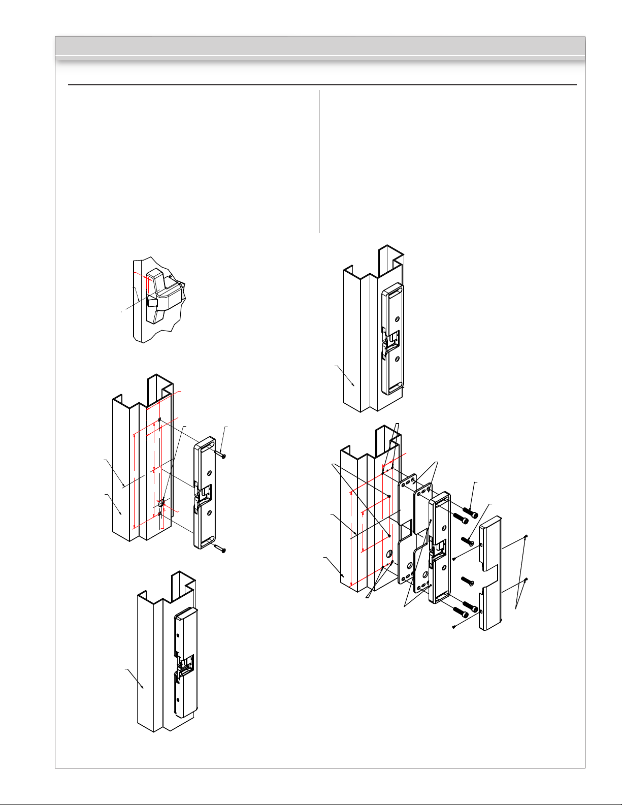
4. Installation
CX-ED1259-L ‘RIM’ Electric Strike
1a. Close door, then mark horizontal center line of Push
bar keeper.
2a. Using center line, measure (101.5mm) top and bottom,
then mark for self-tapping screws.
2b. Drill (15mm dia.) Hole, as per template, for
connecting wires
2c. Fix strike body with SCW425T self-tapping screws.
3. Close door, and if necessary, adjust so that strike and
push bar keeper are well aligned, then mark remaining
screw positions.
HORIZONTAL
CENTERLINE
R
STEP 1
R+23
4a. Remove strike, and drill threads at screws position.
4b. Connect wires as per drawing.
4c. Fix strike with remaining screws (M6 x 30 at both ends /
M5 x 25 in the middle)
4d. Place cover plate on the strike. Install the M2.5 x 4
screws.
Jamb
STEP 3
HORIZONTAL
CENTERLINE
Jamb
Jamb
213
106,5
106,5
21,5
STEP 5
R+28
Wire hole
15
n
Self-tapping SCREWS x 2pcs
(SCW425T)
HORIZONTAL
CENTERLINE
STEP 2
Note: The products are intended to be installed in accordance with the
installation wiring diagram and mechanically assembled drawings
provided with each product. The local authority having jurisdiction (AHJ)
and the National Electric Code, NFPA 70. When installed with a fail secure
manner, the local authority shall be consulted with regard to the use of
possible panic hardware to allow emergency exit from the secure area.
The electric door strike shall be installed in such a way and in such
location as not to impair the operation of an emergency exit or panic
hardware mounted on the door.
M5(2pcs)
Jamb
STEP 4
213
90
M6(2pcs)
M6(2pcs)
25
M2.5(4pcs)
Spacer (Install as needed)
M6 x 30 SCREW x 4pcs
(SC630A)
M5 x 25 SCREW x 2pcs
(SC525E)
M2.5 x 4 SCREW x 4pcs
Page 2 of 3
Page 3

CX-ED1259-L ‘RIM’ Electric Strike
5. Connections
POWER
12V AC/DC
Red/Black: +12V
Blue/Green: Ground
24V AC/DC
Red: +24V
Black/Blue: -
Green: Ground
A varistor is provided to protect/prevent strike from spikes.
Connect varistor between input wires.
Note: The door strikes are to be powered via a class 2 power
limit output from a control panel or power supply that is UL
listed to UL Burglar Alarm/Access control standards.
6. Wiring
Door Status Sensor
(Closed position)
White = N/O
Orange = COM
Grey = N/C
Black
Red
Blue
Green
Grey
White
Orange
7. Setting Fail-Secure/Fail Safe
How to modify fail-safe to fail-secure or vice versa.
1. Loosen the screw at the back of the Electric strike as per
the diagram below.
1.
Remove cover
plate
3.
Rotate 180°to
change the mode
of operation
2.
Slide
mechanism
out
12V
(+12V)
Varistor
(-)
24V
(+24V)
Varistor
(-)
Red
Black
Blue
Green
Red
Black
Blue
Green
Fail secure
Fail safe
A varistor is provided to protect strike from spikes.
Connect varistor to between input wires.
Push Buttons Keypads Strikes Magnetic Locks Key Switches Relays & Timers Access Control
5502 Timberlea Blvd.,
Mississauga, ON Canada
L4W 2T7
www.camdencontrols.com
Toll Free: 1.877.226.3369
File: CX-ED1259LDesigner
Installation Instructions.indd R3
Revision: 22/02/2018
Part No.: 40-82B205
Page 3 of 3
 Loading...