

Page 1

PACKAGE CONTENTS
1
Foam Gasket
1
O Ring
1
Set of Labels
1
LED Base
1
Lens
1
2-28 x 5/16” Phillips locking screw
2
Concrete wall plugs
2
3/16” drywall plugs
2
Wire nuts
2
#6 x 3/4” self-tapping screws
2
6-32 x 3/4” screws
CM-AF141SO
Single Gang LED Dome Light,
with Sounder
Installation Instructions
CM-AF141SO
Description
Camden CM-AF141SO Corridor Lamp provides both visual
and audible annunciation. It mounts to a standard single
gang electrical box. The Superbright LED’s along with the
wedged shaped lamp cover provides visible illumination
from either end of a corridor. The integrated piezo buzzer
with adjustable volume provides up to 93 dB at 1 metre
(3 feet).
Specifications
Voltage: 12 – 24V AC/DC
Illumination: Superbright LED’s
Sounder: Piezo, 93 dB @ 1 metre (3 feet)
Current Rating: 70 mA Max
Dimensions: 4-9/16” x 2-15/16” (115mm x 75mm)
Wiring
Camden CM-AF141SO Corridor Lamp is easily wired using
the 2 non-polarized leads supplied. The 2 black leads can
be connected to either an AC or DC power source supplying
12 or 24V.
Sounder Volume Adjust
Using a small Phillips screwdriver, gently turn the volume
adjustment counter clock wise to reduce the volume and
clockwise to increase the volume.
-
+
12-24
AC/DC
Power
Page 1 of 3
CM-AF141SO Wiring
Page 2
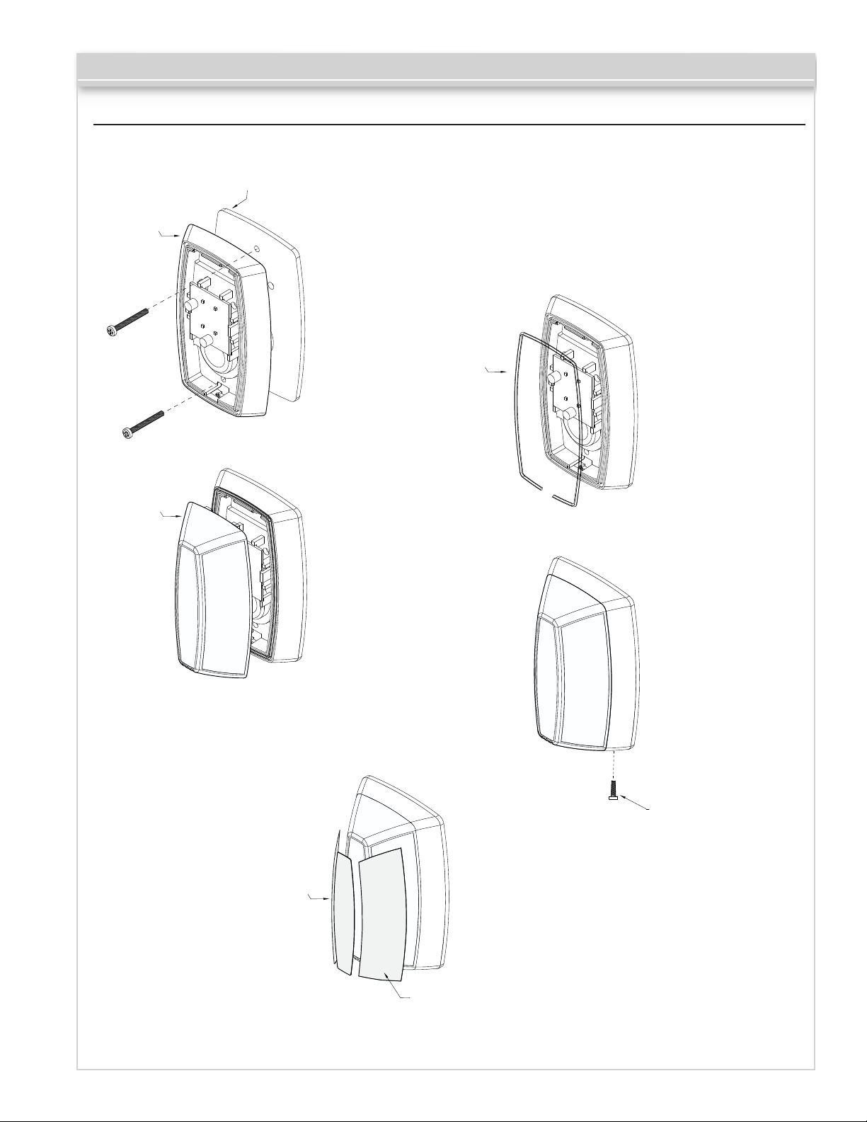
Installation
Camden CM-AF141SO mounts to a standard single gang electrical box.
Gasket
CM-AF141SO Installation Instructions
CM -AF141SO
Base
Lens
STEP
Place the gasket
1
(supplied) between
the base unit and
the electrical box.
Use the 6-32 screws
to fasten the base to
the electrical box.
STEP
Install the Lens by
3
inserting the large
bottom tab in rst.
The top tabs will
snap in place with
a little effort.
O Ring
STEP
Insert the O ring
2
gasket into the
small channel in
the front of the Base.
The O ring does not
completely close
around the base.
You must leave a
small opening at the
bottom of the base.
STEP
Install the Phillips
4
locking screw into
the bottom of the
base.
Labels
STEP
Apply the labels as
5
Locking Screws
required to the lens.
A
S
R
S
E
I
Q
S
U
T
I
A
R
N
E
C
D
E
Labels
Page 2 of 3
Page 3

" [83mm]
1
4
3
CM-AF141SO Installation Instructions
L4W 2T7
Mississauga, Ontario
5502 Timberlea Blvd
FILENAME:
" [40mm]
9
16
1
" [75mm]
16
15
2
" [77mm]
1
16
3
" [115mm]
9
16
4
" [53mm]
1
16
2
Camden Door Controls
CM-AF141SO Emergency Annunciator
CM-AF141SO_Mech.dwg CM-AF141SO_Mech.vsd
DRAWING No:
SCALE: NONE DRAWN BY: J.Lewis 03/09/17 04/26/17REVISED:DATE:
Push Buttons Keypads Strikes Magnetic Locks Key Switches Relays & Timers Access Control
5502 Timberlea Blvd.,
Mississauga, ON Canada
L4W 2T7
www.camdencontrols.com
Toll Free: 1.877.226.3369
File: CM-AF141SO
Installation Instructions.indd R1
Revision: 27/04/2017
Part No.: 40-82B207
Page 3 of 3
 Loading...