

Page 1
Door Activation Devices
Wall
Anchors
Inset
Screws
Mounting
Screws
36”
(914.6mm)
2-1/16”
(52.1mm)
3”
(76.2 mm)
Base
Unit
Floor
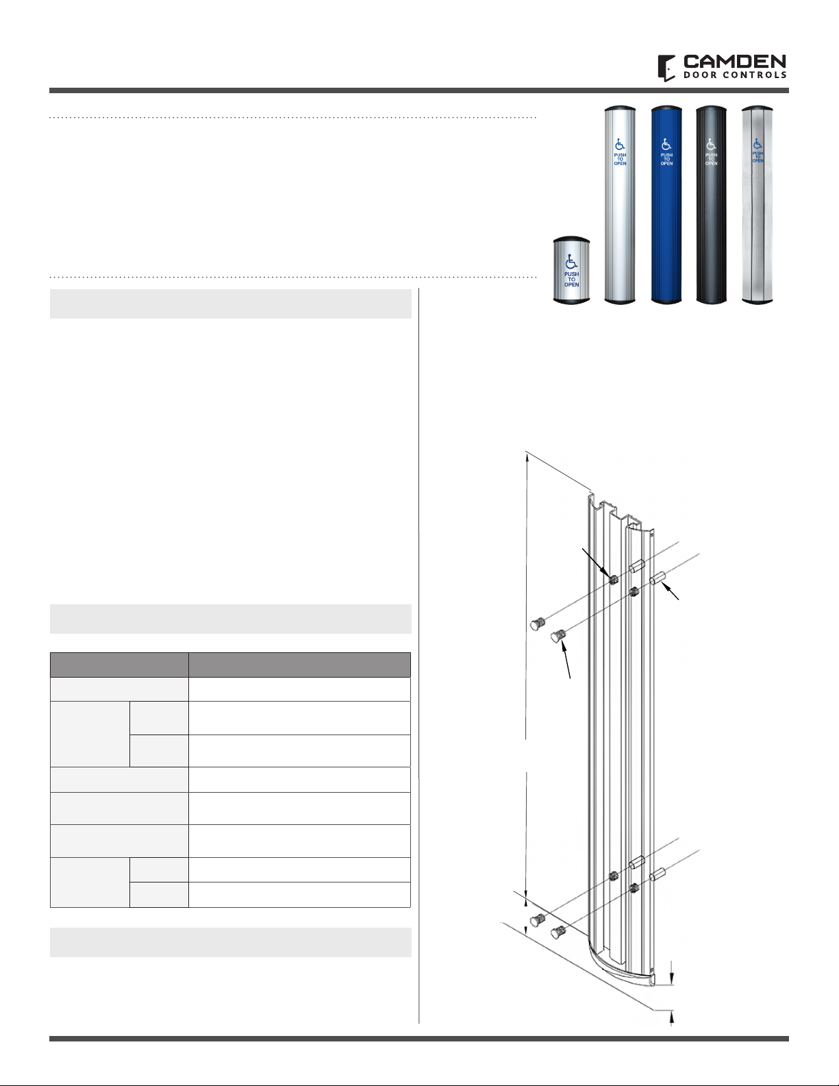
CM-75 Series
Column Switch
INSTALLATION INSTRUCTIONS
1. GENERAL DESCRIPTION
Camden CM-75 Series Column™ switches offer a rugged and
attractive ADA compliant switch design that is easy to activate
from any angle, providing years of trouble-free operation.
CM-7536 utilizes 2 fully redundant 15 amp Form-C contact switches,
and molded impact and ame resistant end caps which provide easy
snap-in installation of the Lazerpoint TX-9 transmitter.
The Column switch may be mounted to any at wall surface,
or to our Model CM-42 or CM-48 anodized aluminum or
stainless steel bollards. We provide necessary mounting
hardware for all options.
The CM-75 Series comes in two congurations (CM-7536 and
CM-7509). CM-7536 uses two switches whereas, the CM-7509
uses one switch. Both models can be hard wired or tted with
either the Kinetic or Lazerpoint wireless transmitters. In the hardwired layout, they will be wired in parallel. The wireless versions
can be paired with Camden Lazerpoint or Kinetic receivers.
2. SPECIFICATIONS
Models CM-7536 and CM-7509
Contact Rating
Contacts
Construction
Finish
Mounting
Dimensions
CM-7536
CM-7509
CM-7536
CM-7509
5 amps @ 30 VDC
2 x SPDT momentary.
Contact switch (Form C), UL listed.
1 x SPDT momentary.
Contact switch (Form C), UL listed.
Heavy duty extruded aluminum
Anodized clear, dark bronze or
stainless steel
4 x #14 wood screws or 1/4"-20 S/S
machine screws with anchors
37 -1/2” H x 5-7/8” W x 1-1/2” D (overall)
10-5/8” H x 5-7/8” W x 1-1/2” D (overall)
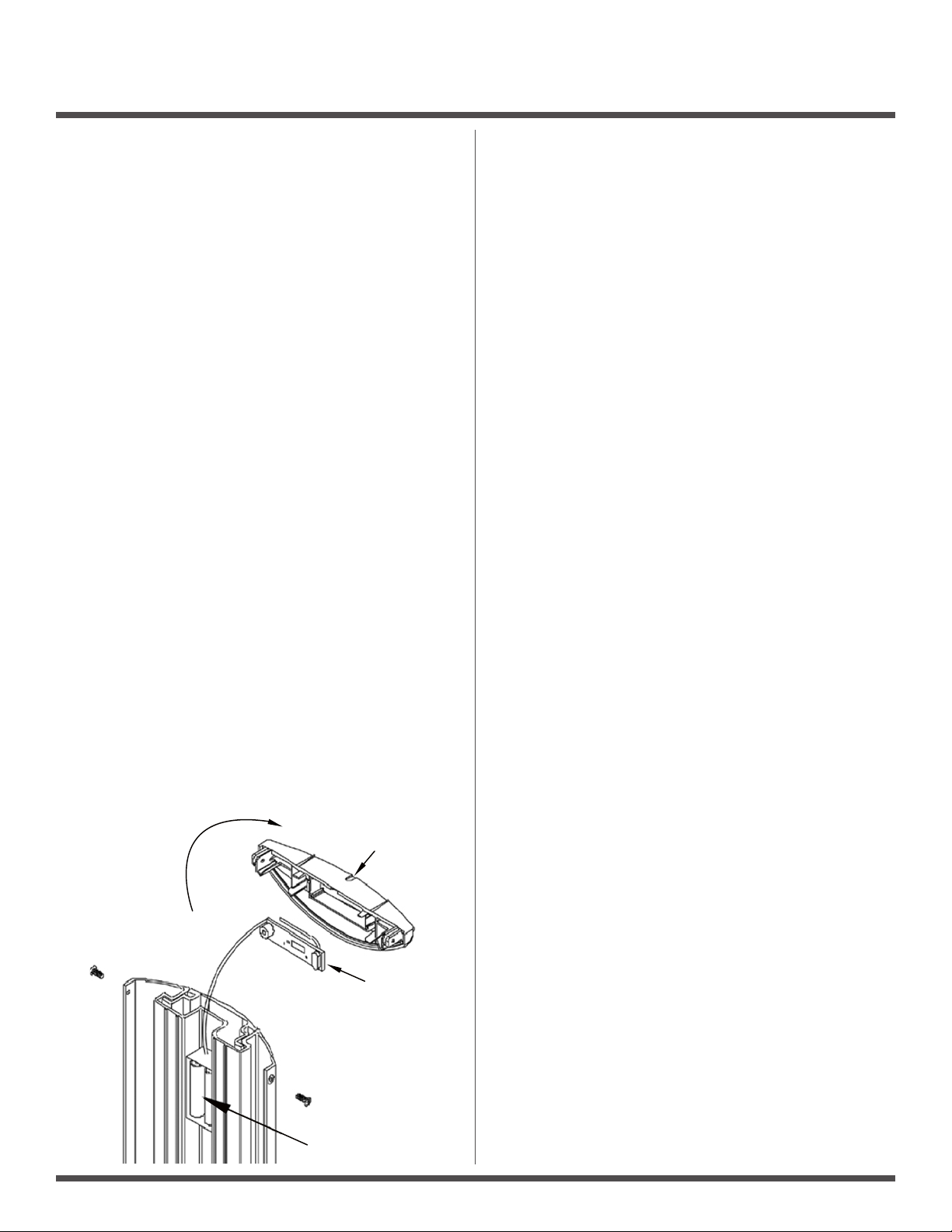
Installation Steps:
1. Remove the assembled unit from packaging. The unit must
be disassembled to be installed. To do this, remove the two
small Phillips screws holding the top cap in place.
Remove the cap. Then, grasping the center (metal) actuation
bar, pull vertically until the entire actuation bar is removed
from the base unit. Set the actuation bar aside and protect
from surface damage.
3. INSTALLATION
Code Requirements: If installed according to these instructions
the CM-7536 Column switch will meet the requirements of the
California Building Code (Section 1117B.6, Date: 2009), and
Section 3.8.3.3.17(b) of the Ontario Building Code.
Page 1 of 4
Page 2
CM-75 SERIES COLUMN SWITCH
Batteries
CM-TX9
End Cap
INSTALLATION INSTRUCTIONS
2. Determine the optimum height from the nished oor.
See illustration (above) for common height. If utilizing an inwall electrical box, center the backplate over the box, while
lining up the top edge with your mark.
3. Using a level, ensure the base unit is plumb and level, and
mark the 4 mounting locations through the adjustable nylon
inset screws onto the wall surface (if on drywall use a pencil,
and if on concrete a narrow Sharpie or similar).
4. a) Drill the wall at the 4 marked locations, and tap in the
appropriate wall plugs. We supply both drywall and concrete
anchors for the included #14 screws.
4. b) If mounting the Column Switch to an aluminum post or
framing section, drill and tap 4 holes for 1/4”-20 Stainless Steel
Machine screws (also provided).
Note: Camden CM-42 and CM-48 series posts are available
with pre-drilled and tapped holes preparation for
Column™ switches.
5. a) If hardwiring: Use the supplied wirenuts to make your
wire connections. Push excess wire into the back box and
ensure cable is not exposed to the moving parts of the switch,
or pinched between the back of the base unit and wall surface.
4 nylon inset screws may be turned in or out to help plump up
Column switch and adjust for wall irregularities. Check with a
level. When satised, install the 4 mounting screws and tighten.
5. b) If using Lazerpoint RF: The cap includes a snap-in
compartment for our TX-9 transmitter. Place transmitter in the
cap, with the wires hanging down and to the front of the cap.
Using the supplied wirenuts, connect the two activating wires
to the Column switch lead wires. Slide the battery and the extra
wiring into the center (rear) channel provided. Do not slide all
of the wire into the channel, so that the cap can hang off to one
side while you perform the next step.
Using the supplied wirenuts, connect the two activating wires
to the Column switch lead wires. Then, slide the battery and the
extra wiring into the center (rear) channel provided. Do not slide
all of the wire into the channel, so that the cap can hang off to
one side while you perform the next step.
5. c) If using Kinetic RF: The CM-7536K uses 2 Kinetic RF
switches installed near the top and the bottom of the
actuator. When pairing this switch with a Kinetic receiver,
you must pair both the top and the bottom switches. The
pairing of Camden Kinetic transmitters is detailed in the
CM-RX90v2 installation manual.
5. d) If using other RF: Using the supplied wirenuts, make your
wire connections to the RF transmitter and tuck the transmitter
and excess wire into the back box (or wall cavity). Ensure cable
is not exposed to the moving parts of the switch, or pinched
between the back of the base unit and the surface of the wall.
6. Reassemble the (center) actuation bar into base unit. This is
done by holding the hanger (located at the top center) vertically
‘up’ – then carefully sliding actuation bar down the length of
the base unit, being careful not to bend or break the springs or
internal switches.
When the bottom edge of the actuation bar reaches the height
of the springs, use your free hand to tuck in the spring and
switches under the actuation bar as it slides over them. When
activation bar is approx 2” from bottom, position hanger so it
falls into the slots provided at the top of the base unit. Slide
actuation bar down until it rests on the hanger. Actuation bar
should now move freely within the base unit. Test the operation
of the switch before mounting the cap.
7. When satised with the switch operation, place cap back on
top, and screw in the two small self-tapping Phillips screws.
Page 2 of 4
Page 3
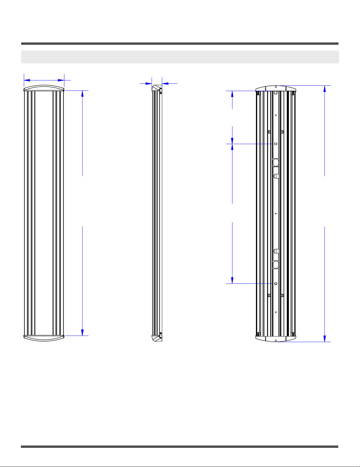
4. CM-7536 ASSEMBLY
CM-75 SERIES COLUMN SWITCH
INSTALLATION INSTRUCTIONS
5-7/8” (150mm)
36”
(914mm)
or
9”
(229mm)
1-1/2” (38mm)
7-3/4”
(196.85mm)
20-1/2”
(521mm)
37-1/2”
(955mm)
or
10-5/8”
(270mm)
Page 3 of 4
Page 4
CM-75 SERIES COLUMN SWITCH
INSTALLATION INSTRUCTIONS
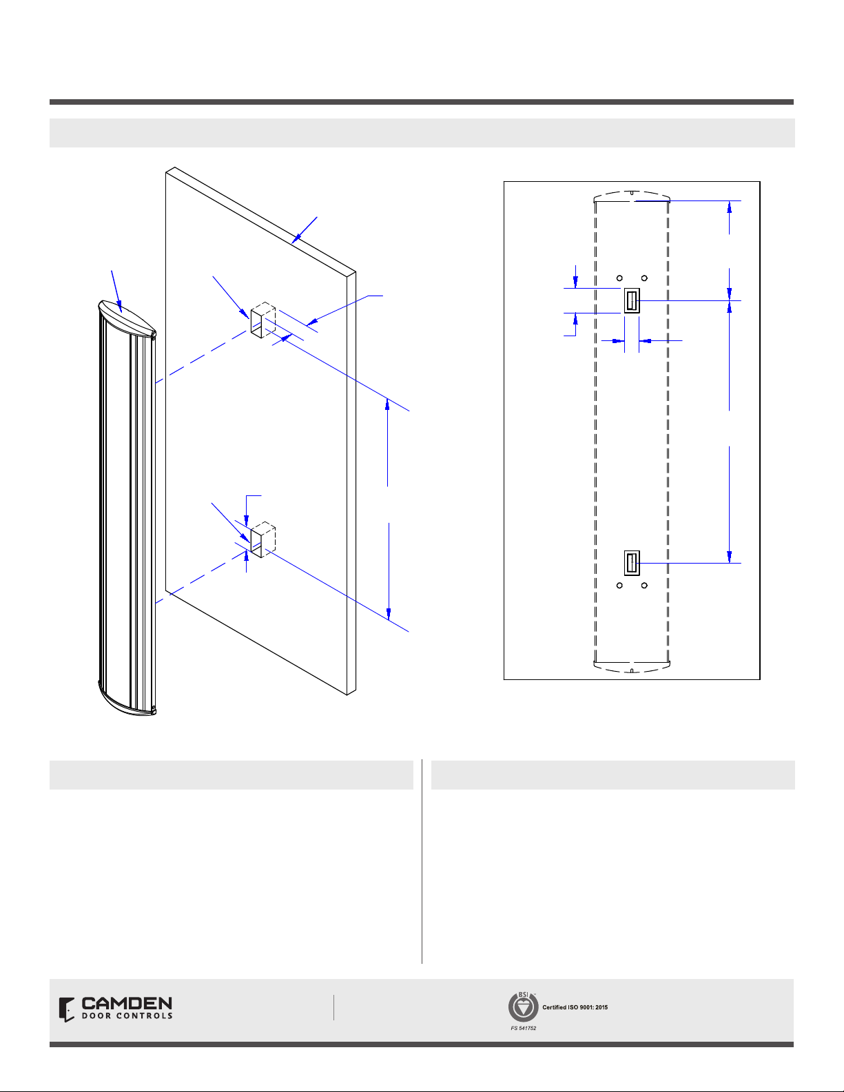
5. KINETIC WITH COLUMN SWITCH AND MOUNTING AGAINST WALL
Wall
CM-7536 with
Kinetic Switch
Kinetic Switch
Cut-Out
Kinetic Switch
Cut-Out
1-7/8”
(48.25mm)
Cut-Out Depth
1-3/4”
(43.7mm)
20-1/2”
(520.70mm)
1-7/8”
(48.25mm)
7- 3/4”
(196.85mm)
1-1/8”
(29.14mm)
20-1/2”
(520.70mm)
6. SYSTEM INSPECTION
After the Installation and operational check of the system:
1. Place any applicable labels on the door (as per ANSI A156.10
or A156.19 guidelines).
2. Instruct the owner on door system operation and how to
test it. This should be checked on a daily basis.
3. Strongly recommend to the owner that the complete entry
be inspected twice a year as part of the service agreement.
Opening New Doors to
Innovation, Quality and Support!
Page 4 of 4
Call: 1.877.226.3369 / 905.366.3377
Visit: www.camdencontrols.com
7. WARRANTY
Camden Door Controls guarantees the CM-75 series to be
free from manufacturing defects for 3 years from date of sale.
If during the rst 3 years the Column™ switch fails to perform
correctly, it may be returned to our factory where it will be
repaired or replaced (at our discretion) without charge.
Except as stated herein, Camden extends no warranties
expressed or implied regarding function, performance
or service.
File: CM-75 Manual R2.innd
Rev.: April 24, 2020
Part No.: 40-82B143
 Loading...