

Page 1
Door Activation Devices
Aura™ CM-54i
Surface Mount Illuminated Enclosure
INSTALLATION INSTRUCTIONS
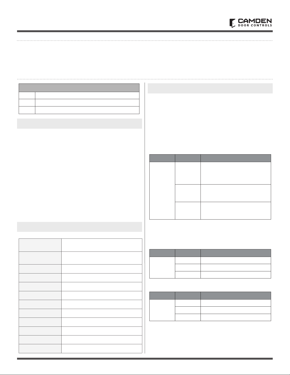
Package Contents
1 CM 54i
1 Blue/Green/Red Aura PCB
2 # 6 X 3/8 Screws
1. GENERAL DESCRIPTION
Camden Aura™, Model CM-54i provide the Industry’s 1st “Changing
State” illuminated switch enclosures.
They offer eld selectable blue/green/red illumination, activated
directly by the switch or remotely by a relay* such as our CX-33
or EMF-2, a time-clock or access control system. User selectable
features include a 3 Amp Form ‘C’ relay, and piezo speaker for
audible annunciation, as well as control over the idle and active
LED colours. Another exclusive is the ability to plug in a TX-9 RF
transmitter, thereby requiring only 2 conductors be run for power
(& no batteries required)!!
The box is made of impact and ame resistant black ABS, and
compatible with any Camden CM-41, CM-45, or CM-46 series switch.
The illumination is provided by an array of super-bright and energy
ecient LED’s, which can be powered by 12 or 24 volts AC/DC.
2. SPECIFICATIONS
3. SETUP
Switch SW1 contains a bank of 3 dipswitches.
Dipswitch # 3 turns the speaker on or off. Dipswitch # 2 toggles
operation of the relay, and # 1 allows you to choose whether
the colour will be changed locally via the push switch, or
remotely.
*Note: The CX-22 Washroom relay may be used with the
Aura™, however an isolating relay must be wired in parallel
with the lock, and the relay’s dry contact output wired into
the CM-54i.
Switch Position Description
SW1
Color selection is made with Switches SW2 and SW3. SW2
determines the Active colour and SW3 determines the Idle color.
1 REMOTE / LOCAL On to enable
LED colour change from idle to
Active with press of the push
button.
2 RELAY On to enable operation of
the relay with activation of the
push button.
3 SPEAKER On to enable operation
of the speaker with activation of
the push button.
Dimensions
Construction
Finish
Mounting
Input Voltage
Output Voltage
Current draw
Sounder
Lumina Red
Lumina Green
Relay Contact
Contact Rating
6 1/2” H x 6 1/2” W x 2” D
(165 mm x 165 mm x 51 mm)
Flame-resistant black ABS
(Insert – translucent ABS)
Attractive pebble nish
4 x #12 wood screws with anchors
12 or 24V AC/DC
3 Volts DC for TX-9 (only)
150 mA (max)
3200 ± 300 Hz @ 85 dB
14.8 lumens, 1600 mW
3.8 lumens, 330 mW
1 x Form C
3A @ 30 VDC
Setting the Active Color (SW2)
Switch Position Description
SW2
1 ON = Green LED when Active
2 ON = Red LED when Active
3 ON = Blue LED when Active
Setting the Active Color (SW3)
Switch Position Description
SW3
Note: If all DIP switches are in the OFF position, there will
be no color illuminated. This allows for no Idle color or no
Active color.
Once all DIP switches are set, proceed to Section 4 – Installation.
1 ON = Green LED when IDLE
2 ON = Red LED when IDLE
3 ON = Blue LED when IDLE
Page 1 of 5
Page 2

CM-54i SURFACE MOUNT ILLUMINATED ENCLOSURE
INSTALLATION INSTRUCTIONS
4. INSTALLATION
NOTE: If you will be including the optional Aura™ signage,
follow that product’s installation instructions before
installing Aura™
1. Determine the wire access location and drill hole of sucient
size, or use center knock-out plug. Drill the four required
mounting holes. (11/64” min.) There are four indents
provided on 3” centers for your convenience. (See Diagram 1)
2. Pull wiring through access hole, and mount the box to wall
using 4 screws.
3. Remove circuit board from package and locate into the box.
Pull the wire through the hole in centre of circuit board, and
then secure with the two small self-tapping screws (provided).
4a. Wire as per diagram 2 (typical installation). Route the switch
wiring through opaque diffuser panel, and install diffuser
panel into box. It should t snuggly.
4b. If using a TX-9 transmitter to send the signal to an
RX-91 or RX-92 Receiver, attach the transmitter and wire it
before installing circuit board into the enclosure and tting
diffuser. See Diagram 3.
5. Screw in two #6-32 Allen-head screws (provided with switch)
into the threaded center inserts, then attach wires to switch
and install switch over screws. Using the Allen key (provided),
locate the screws and tighten (by hand only).
6. Connect power and test for proper operation
5. WARRANTY
Camden Door Controls guarantees the Aura™ (CM-54i series)
to be free from manufacturing defects for 3 years from date
of sale.
If, during the rst 3 years, the Aura™ fails to perform correctly,
it may be returned to our factory where it will be repaired or
replaced (at our discretion) without charge. Except as stated
herein, Camden extends no warranties expressed or implied
regarding function, performance or service.
Page 2 of 5
Page 3

CM-54i SURFACE MOUNT ILLUMINATED ENCLOSURE
INSTALLATION INSTRUCTIONS
CM-55i Box
5502 Timberlea Blvd.
Mississauga, Ontario
L4W 2T7
PCB
TM
Aura
Diffuser
CM-54i Dimensional & Assembly Diagram
2 x #6 x 3/8”
Pan head
Phillips Screws
for mounting
PCB to box
CAMDEN DOOR CONTROLS
2 x 6-32 x 1 1/2”
CM-554i Dimensional & Assembly Diagram
DRAWN BY: DGW DATE: 04/26/17 REVISED:
SCALE: NONE
Allen Screws to
mount the switch
DRAWING No: DRG-CM-54i_01 FILE NAME: CM-54i diagram 1.vsd
to box assembly
Page 3 of 5
CM-45
Push Plate
PUSH
TO OPEN
Page 4

CM-54i SURFACE MOUNT ILLUMINATED ENCLOSURE
INSTALLATION INSTRUCTIONS
(x2)
5502 Timberlea Blvd.
Mississauga, Ontario
L4W 2T7
Power & Relay
Switch mounting holes (x2)
Terminal Strip
Circuit Board Mount
PWR 10-30
NO COM NC
ACV/DCV
SW3
BLUE
RED
2 3
GREEN
1
ON
IDLE COLOR
2 3
1
ON
CM-54i Wiring Diagram (Typical)
SW2SW1
2 3
1
ON
ACTIVE
- PBTN+
ENABLE
-54 Enclosure
Box mounting screw locations
- REM + RF-TX +
SPEAKER
RELAY
REM/LOC
CM
Diuser Ring
(sold separately)
All -Active Switch
Camden Door Controls
FILENAME: CM_54i Diagram 2.vsd
CM-54i Wiring Diagram (Typical)
DRAWING No: DRG-CM-54i _02
SCALE: NONE DRAWN BY: DGW 04/26/17 REVISED:DATE:
Page 4 of 5
SW3 Dipswitch
SW2 Dipswitch
SW1 Dipswitchh
Wire Access Hole
Door
Power
AC/DC
12 / 24 V
Device
operator
or Locking
or Relay
or EMF-2
ie - CX-33
Remote Switch
changes LED colour. If it is desired to have switch
NOTES:
1. Power terminals are not polarity sensitive.
activation change LED colour, then set REMote /
2. Typical installation shown, where remote device
REMOTE terminals .
LOCal dip on SW1 to LOCAL, and do not wire to the
Page 5

CM-54i SURFACE MOUNT ILLUMINATED ENCLOSURE
INSTALLATION INSTRUCTIONS
PWR 10-30
NO COM NC
ACV/DCV
5502 Timberlea Blvd.
Mississauga, Ontario
L4W 2T7
CM-54i & TX-9
Power
AC/DC
12 / 24 V
BLUE
RED
GREEN
2 3
1
ON
SW3
IDLE COLOR
RF-TX +
SW2SW1
2 3
1
ON
ACTIVE
Connect the 3 wires from the TX-9 to
STEP 3
- PBTN+
- REM +
SPEAKER
RELAY
2 3
REM/LOC
1
ON
ENABLE
CM-TX-9
CAMDEN
LAZERPOINT
2 power wires as shown.
Install circuit board in box, & connect the
the circuit board exactly as shown.
The middle red wire that was cut short
is not used.
Set dipswitches for desired operation.
STEP 4
Diuser
Install diuser, connect push switch wires to
terminal strip, then install switch.
Test for proper operation.
Switch
FILENAME: CM_54 i Diagram 3.vsd
Camden Door Controls
Wiring Diagram for CM-54i & TX-9
SCALE: NONE DRAWN BY: DGW REVISED:DATE: 04/26/17
DRAWING No: DRG-CM-54i_03
-
+
-
-
+
+
2“
<< Cut this lead to ¼”
TX-9
CAMDEN CM-TX-9
LAZERPOINT
Opening New Doors to
Innovation, Quality and Support!
STEP 1
Cut the middle red lead to 1/4”as it is not used.
Cut both battery leads, and the remaining
switch lead to approximately 2” long.
Strip the insulation back on the 3 long ends to
approximately 1/4”.
Call: 1.877.226.3369 / 905.366.3377
Visit: www.camdencontrols.com
STEP 2
Turn over, and remove release paper
from double sided tape.
Line up and carefully install TX 9 on
back surface of mounting box
NOTES:
File: CM 54i Manual_R1 Eng.indd
Revision: 05/05/17
Part No: #40-82B208
applications.
1. 12/24 Power terminals are not polarity sensitive .
2. This installation is intended for 2-wire retrot
Page 5 of 5
 Loading...