

Door Activation Devices
CM 325 Series
Short Range “Hands-Free” Switch
INSTALLATION INSTRUCTIONS
1. GENERAL DESCRIPTION
Sure-Wave™ hands-free” switch is an active infrared device
designed for use with an automatic door operator or other
access control product.
The CM-325 Hand-Free Infrared Switch is a special short-range
version intended for such applications as hospital operating
rooms, corridors, drive up windows, etc.
The assembly will t in a variety of locations from a
1 3/4” door frame to a 1-gang or 2-gang electrical box. Various
size surface mounting boxes are also available from Camden.
Three standard face plate widths are available:
CM-325: 2 ¾” x 4 ½” polycarbonate or stainless steel, ts on
single gang electrical boxes.
CM-325/ N: 1 ¾” x 4 ½” polycarbonate or stainless steel, ts 1 ¾”
door frames or our CM23D Jamb box.
CM-325/ W: 4 ½” x 4 ½” polycarbonate or stainless steel, ts on
single gang, double gang or 4 x 4 electrical boxes.
All faceplates may be ordered up with a plain face (/1), with the
waving hand symbol (/2), or with the waving hand symbol and
words: WAVE TO OPEN (/3).
Current Draw
Response Time
Activation Range
Relay Output
Relay Contact Rating
Output Type
Connections
Time Delay
Electrical Life
50 - 60 mA.
100 ms.
Minimum:
2" (51mm)
Maximum:
18" (457mm) Factory Set to
6" (152mm)
Form C (SPDT)
5 amps @ 30 VDC
Normal or Fail-Safe
11” 22 AWG Leads
1 to 5 Seconds
100,000 Operations @
Rated Capacity
500,000 Operations @ ½ Rated
Capacity
2. SPECIFICATIONS
Body Size
Mounting
Faceplates Sizes
Technology
Security
Operating Modes
Operating Temp
Operating Voltage
4" L x 1" W x 1 ½" D
2 x #6-32 MS
Jamb, 1-gang, & 2-gang
Infra-Red with Coded
Modulated Carrier
Automatic Self-changing ID
Pulse (sense) / Toggle
-4 to +153 ºF (-20 to +85 ºC)
12-24 Volts, AC/DC ± 12%
3. INSTALLATION
MOUNTING
Sure-Wave™ may be mounted in door jambs, single or double
gang electrical boxes, and 4 x 4 boxes.
NOTE: The sealing gasket (included) is recommended for
outdoor or wet locations. If using with Automatic doors
install in accordance with ANSI A156.10 / A156.19. Select
from one of the following three mounting subsections:
SINGLE GANG ELECTRICAL BOX: CM-325
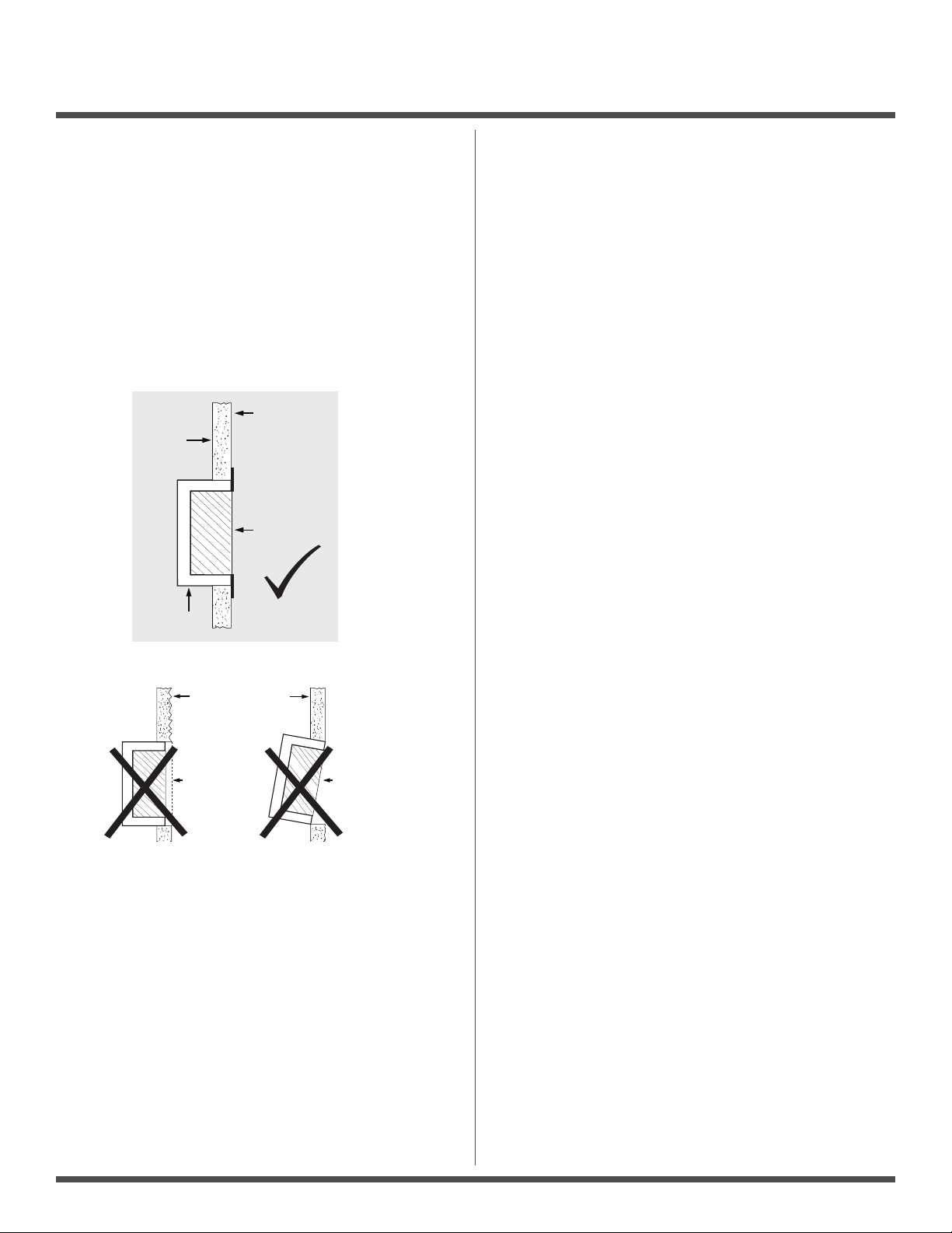
1a – If using an in-wall box ensure the box is plumb and square,
and ush with the wall surface. (See Diagram 1)
1b – If using a surface box, ensure it is secure & plumb.
2 – Bring your 4-conductor wire through the back or side of
the enclosure and leave approximately 6” tail for wiring
connection.
Page 1 of 2
CM-325 SERIES SHORT RANGE “HANDS-FREE” SWITCH
INSTALLATION INSTRUCTIONS
3 – Make the electrical connections to the device according to
the wiring section (following).the wiring section (following).
4 – Using the dip switch located on the end of the unit, set the
operating mode. (See Section 4)
5 – Attach the unit to the enclosure using the two #6-32 screws
provided.
6 – Apply power and adjust range and time delay via the
potentiometers on the front of the unit. (See Section 4 for
adjustments)
7 – Attach the faceplate to the unit using the two black #6-32 x
3/8 machine screws or tamperproof screws.
Do not overtighten!!
Smooth
Wall
Wall Box
Rough Wall
Recessed
Box
PROPER BOX INSTALLATION
Wall Finish
Flush
Finish
Unaligned
Box
DIAGRAM 1
2-GANG (or 4x4) ELECTRICAL BOX: CM-325W
1a – If using an in-wall box ensure the box is plumb and square,
and ush with the wall surface. (See Diagram 1)
1b – If using a surface box, ensure it is secure & plumb.
1c – If using a 4 x 4 box, ensure the box is plumb and square,
and ush with the wall surface, then attach the metal
adaptor plate (included in the CM-325W package) to the
box using appropriate fasteners.
2 – Bring your 4-conductor wire through the back or side of
the enclosure and leave approximately 6” tail for wiring
connection.
3 – Make the electrical connections to the device according to
the wiring section (following).
4 – Using the dip switch located on the end of the unit, set the
operating mode. (See Section 4)
5 – Attach the unit to the enclosure using the two #6-32 screws
provided.
6 – Apply power and adjust range and time delay via the
potentiometers on the front of the unit. (See Section 4 for
adjustments)
7 – Attach the faceplate to the unit using the two black #6-32 x
3/8 machine screws or tamperproof screws.
Do not overtighten!!
DOOR FRAME: CM-325N
1a – If mounting directly in a 1¾” wide aluminum jamb, make a
cutout in the door frame at the intended location as per
Diagram 2. (See Diagram 2 on page 4)
Drill and tap two mounting holes as shown.
1b – If mounting the unit in our CM-23D deep jamb box,
rst mount the jamb box according to the instructions
packaged with the enclosure. Using the CM-23D as a guide,
drill a wire access hole through the jamb to sh the wiring
through.
2 – Bring your 4-conductor wire through the back or side of the
enclosure (or Jamb) and leave approximately 6” tail for wiring
connection.
3 – Make the electrical connections to the device according to
the wiring section (following).
4 – Using the dip switch located on the end of the unit, set the
operating mode. (See Section 4)
5 – Attach the unit to the enclosure or jamb using the two #6-32
screws provided.
6 – Apply power and adjust range and time delay via the
potentiometers on the front of the unit. (See Section 4 for
adjustments)
7 – Attach the faceplate to the unit using the two black #6-32 x
3/8 machine screws or tamperproof screws.
Do not overtighten!!
WIRING
CAUTION: Do not apply power to the unit until all secondary
wiring is complete, and dip-switches have been set.
The CM-325 can be powered from 12 or 24 volts, AC or DC.
Connect the two Red wires, (which are non-polarity sensitive) to
the power source.
The output is a form C relay. N.O is Blue, N.C. is Violet, and
Common is Green. Selecting the correct output is also
dependant on the operating mode chosen. (See Section 4)
Most applications will utilize the N.O. and Common terminals.
Page 2 of 4

12-24V
DIAGRAM 5 - WHEELCHAIR STICKER PLACEMENT
CM-325 SERIES SHORT RANGE “HANDS-FREE” SWITCH
INSTALLATION INSTRUCTIONS
4. APPLICATIONS & SET-UP APPLICATIONS
See Diagram 3 for the location of the Dip switches.
Range
Adjustment
Photo Eye
Red LED
Time Delay
Adjustment
LOCATION OF ADJUSTMENTS
CM-325
Dip Switch
DIAGRAM 3
Switch 1 – Normal Mode/Fail-Safe Mode
Choose Normal Mode if you wish the N.O. contact to remain
open if the power were to fail. This is the factory setting.
Choose Fail-safe Mode if you wish the contacts to close upon
power fail. Move the Dip switch to OFF position, and wire your
device to the Common and N.C. wires.
Switch 2 – Time Delay Mode/Toggle Mode
Factory setting is Time Delay (Sense) mode, whereby the
contact closure will be adjustable from 1 – 5 seconds using the
Time Delay Potentiometer.
In Toggle (or Switch) mode, when the CM-325 is activated once,
the relay will stay energized until it is activated once again.
(The adjustable timer is inactive in this mode)
Wiring Pigtail
Red
Red
Blue
Green
Violet
Power
N.O.
COM
N.C.
until the desired time delay is obtained. It is sometimes
benecial to leave this adjustment set to minimum and utilize
the time delay on the door operator, if present.
NOTE: Timer is non-functional in Toggle Mode. Install the
faceplate using the screws provided.
Do not overtighten!!
Door Frame
CM-325/N3
1
"
25mm
WHEELCHAIR STICKER PLACEMENT
OPTIONAL – Apply the included Wheelchair logo to the frame
or wall at desired location. See Diagram 5.
Do not apply directly to the faceplate!!
If using this product with an Automatic Door, proceed to
Section 5 for System Inspection Instructions.
DIAGRAM 5
Switch 3 – LED On/LED Off
This switch disables the LED, should this feature be desired.
Factory setting is ON.
Once the Dip switches have been set, and the unit is installed
in the frame or enclosure, apply power to the unit and observe
operation.
Set both potentiometers to minimum setting initially (fully
counter-clockwise). See Diagram 3 for location. Adjust the range
potentiometer by turning the pot in a clockwise manner, and
passing your hand in front of the unit. Rotate the pot until the
desired range is obtained. See Diagram 5 for patterns.
Next, adjust the time delay potentiometer by turning clockwise
5. SYSTEM INSPECTION INSTRUCTIONS
After the Installation and operational check of the system:
1. Place warning label on the door (as per ANSI A156.10 or
A156.19 guidelines). This will advise the person entering the
swing side zone that the door will move.
2. Instruct the owner on door system operation and how to
test it. This should be checked on a daily basis.
3. Instruct the owner on what to do if the door or any of its
components become damaged.
4. Strongly recommend to the owner that the complete entry
be inspected twice a year as part of the service agreement.
Page 3 of 4

6. WARRANTY
1
Camden Door Controls guarantees the Sure-Wave™ to be free
from manufacturing defects for 3 years from date of sale.
If during the rst 3 years the CM-325 fails to perform correctly,
it may be returned to our factory where it will be repaired or
replaced (at our discretion) without charge. Except as stated
herein, Camden extends no warranties expressed or implied
regarding function, performance or service.
1
/2"
38 mm
CM-325 SERIES SHORT RANGE “HANDS-FREE” SWITCH
INSTALLATION INSTRUCTIONS
2”
(51mm)
18”
(457mm)
9
/32"
3
83mm
Drill & Tap
6-32 (2 holes)
DIAGRAM 4A
JAMB CUTOUT DIMENSIONS
7
/8"
2
73mm
0’
1’
ADJUSTABLE RANGE SETTINGS
2’
DIAGRAM 4B
3’
OBJECT MIN MAX
1/ Hand
2/ 8 1/2” x 11” white paper 3 1/2” 4 1/2”
3/ S/S Chrome Post 5” 6"
4/ S/S Plate 12” x 12” 7” 9”
5/ Small make-up mirror 11” 18”
2”
3”
Opening New Doors to
Innovation, Quality and Support!
Call: 1.877.226.3369 / 905.366.3377
Visit: www.camdencontrols.com
File: CM-325 Manual_R2 Eng.indd
Revision: 03/05/2018
Part No: #40-82B137
Page 4 of 4
 Loading...