

Page 1
Door Activation Devices
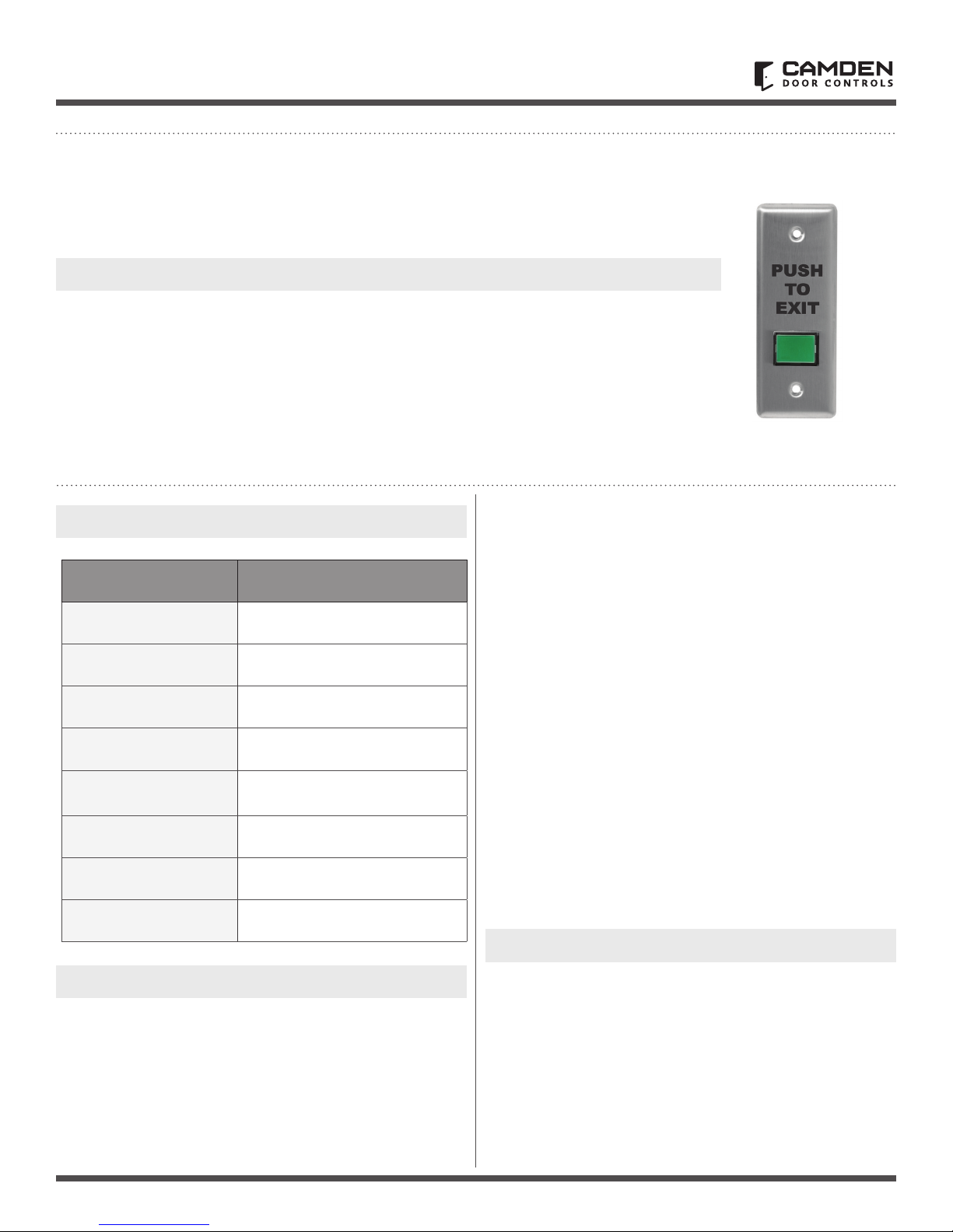
CM-310EE
Exit Switch & Integrated Timer (Ver. 2)
INSTALLATION INSTRUCTIONS
1. GENERAL DESCRIPTION
Camden model CM-310EE is an illuminated
Exit switch incorporating a 30 second timer.
The stainless steel faceplate is designed to ush
mount on to a 1 ¾” wide doorjamb.
The ½” x ¾” rectangular translucent button is easy
to push. CM-310EE model is supplied with a LED
light bulb, which is accessed through the front
of the switch. If the unit is powered 24VDC, the
supplied in-line resistors must not be removed.
2. SPECIFICATIONS
Models CM-300
Operating Voltage
Time Delay
Contact Rating
Incandescent
Bulb Life
Mounting
Lens Colour
12 or 24 V DC
30 seconds
4 amps @ 30 VDC
15,000hrs.@ rated capacity
2 x #6-32 machine screws
Green
This switch has been designed specically to
release a magnetic lock from the inside, as per
the BOCA code. When the button is pushed and
released, the lock will release for 30 seconds.
Re-trigger is possible at any time.
The “double break” circuitry has been designed so
that even if the timer fails, depressing the switch
will interrupt power to the magnetic lock.
Wiring
Six color coded leads are provided. This unit will operate on 12 or
24 VDC, with no jumper change required. For convenience it may
be powered by the same power that supplies the magnetic lock.
The two pairs of Red & Black wires connect to 12 or 24 VDC.
One pair supplies power to the timer, and the other pair powers
the light. The internal timer and the push button are connected
in series with the Green & White wires. This is how the “double
break” feature works. Therefore, the unit must be wired as
shown.
The Green wire goes to the positive input wire of the magnetic
lock, and the White wire goes to a source of + Voltage. Please
refer to the enclosed wiring diagram for typical hook-up.
Important:
CM-310EE models have connected lead wires with
black-colored heat shrink (over an in-line resistors).
CM-310EE
Legend
Dimension
'PUSH TO EXIT'
2.75” W x 4.5” H x 1 5/16”
(70mm x 114mm x 33mm)
3. INSTALLATION
Mounting
The unit is completely pre-wired for easy installation. Connect
the appropriate wires to your devices as per the enclosed wiring
diagram. Tuck wiring into box (retrot box included), and fasten
switch plate using screws provided.
If powered 24V; Do not remove in-line resistors.
If powered 12V; Cut (remove) in-line resistor on the
black lead.
4. LIMITED WARRANTY
Camden Door Controls Inc. warrants this product to be free
from defects for 3 years from date of manufacturing. Visit our
web site at www.camdencontrols.com to see our complete
warranty policy, including limitations and the procedures for
product returns.
Page 1 of 2
Page 2
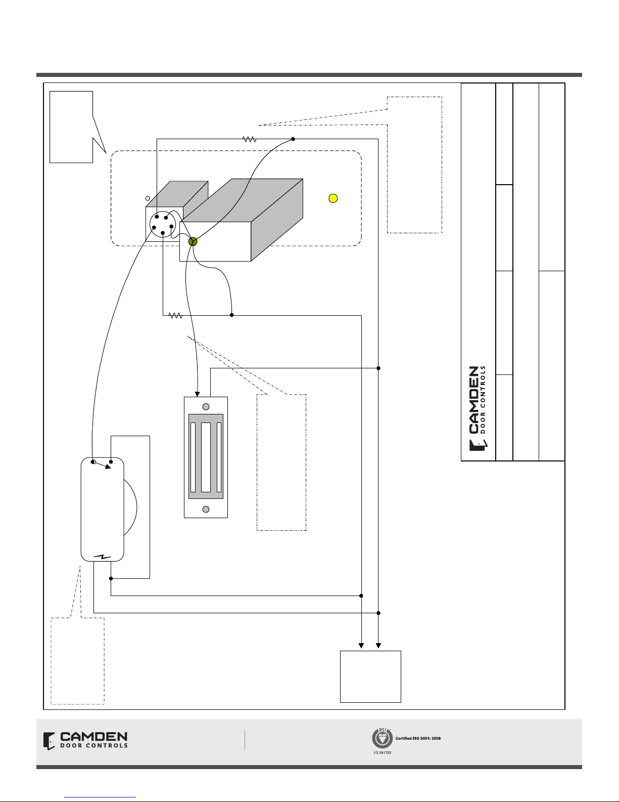
Rear View of
CM-310EE switch
and Faceplate
Black
(Light)
Inline
Resistor
Black
CM-310EE SERIES
INSTALLATION INSTRUCTIONS
5502 Timberlea Blvd.
Mississauga, Ontario
L4W 2T7
Note:
If powered 24V; Do not remove
If powered 12V; Cut (remove) in-line
resistor on the black lead.
in-line resistors.
or,
Wire White to “+” 12/24 VDC,
through Relay of Motion Detector (optional)
Motion Detector
Power In Relay Out
White
Red (Light)
Inline
Resistor
Green
“+”
Red
“-”
Lock
Magnetic
Note:
CM-310EE models have a connected
lead wire with black-colored heat
shrink (over the in-line resistors)
Camden Door Controls
DRAWN BY: DGW DATE: 03/18/03 REVISED: 03/20/12
CM-310EE Egress Switch Wiring Diagram (Ver 2.0)
SCALE: NONE
DRAWING No: DRG-CM310EE-031703 FILE NAME: CM-310EE Diagram.vsd
Optional Motion
Detector shown.
If not used, wire White
to Positive Terminal of
power supply.
Opening New Doors to
Innovation, Quality and Support!
Call: 1.877.226.3369 / 905.366.3377
Visit: www.camdencontrols.com
+
VDC
12/24
-
POWER
Note:
1.For 12V operation, cut off inline-resistor
(on Black wire only). For 24V operation, leave
inline resistor in place.
2.Bulb Replacement.
Access to light bulb is obtained by first removing
front rectangular lens with a thin blade screwdriver.
Then, using a pair of needle-nose pliers, carefully
pull light bulb straight out.
Re-installation is reverse of above sequence.
Be sure to line up both pins before pushing bulb in.
File: CM-310EE Series
Installation Instructions.indd R2
Revision: 30/10/2018
Part No.: 40-82B040
Page 2 of 2
 Loading...