

Page 1
Door Activation Devices
CM-300 Series
Exit Switch
INSTALLATION INSTRUCTIONS
1. GENERAL DESCRIPTION
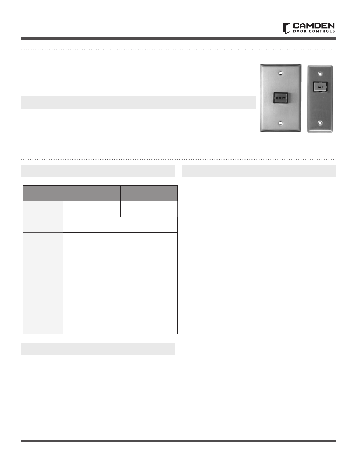
Camden CM-300 series illuminated Exit
switches are available with stainless-steel
single-gang faceplate (CM-300), or with
Narrow jamb size faceplate (CM-310).
The 1/2” x 3/4” illuminated translucent button
is easy to push, and supplied in momentary or
2. SPECIFICATIONS
Models CM-300 CM-310
Dimensions
Contacts
Switch
Rating
Electrical
Life
Mounting
2.75” W x 4.5” H x 1 5/16”
(70mm x 114mm x 33mm)
Mom. / Maint.
10 amps @ 125 VAC
100,000 @ rated capacity
2 x #6-32 machine screws
1.75” W x 4.5” H x 1 5/16”
(44mm x 114mm x 33mm)
maintained models. Red buttons are standard
but blue and green are also available.
The supplied LED will work on 12 volts, or
24 volts (using supplied inline resistor).
3. WARRANTY
Camden Door Controls guarantees the CM-300 series to be
free from manufacturing defects for 3 years from date of sale.
If during the rst 3 years a CM-300 series switch fails to perform
correctly, it may be returned to our factory where it will be
repaired or replaced (at our discretion) without charge. There
is no warranty for bulb damage due to over voltage! Except as
stated herein, Camden extends no warranties expressed or
implied regarding function, performance or service.
CM-300RE CM-310E
Lens
Colour
Legend
LED
Voltage
Red, Green, or Blue
'EXIT'
12 or 24 V DC
2. INSTALLATION
Mounting
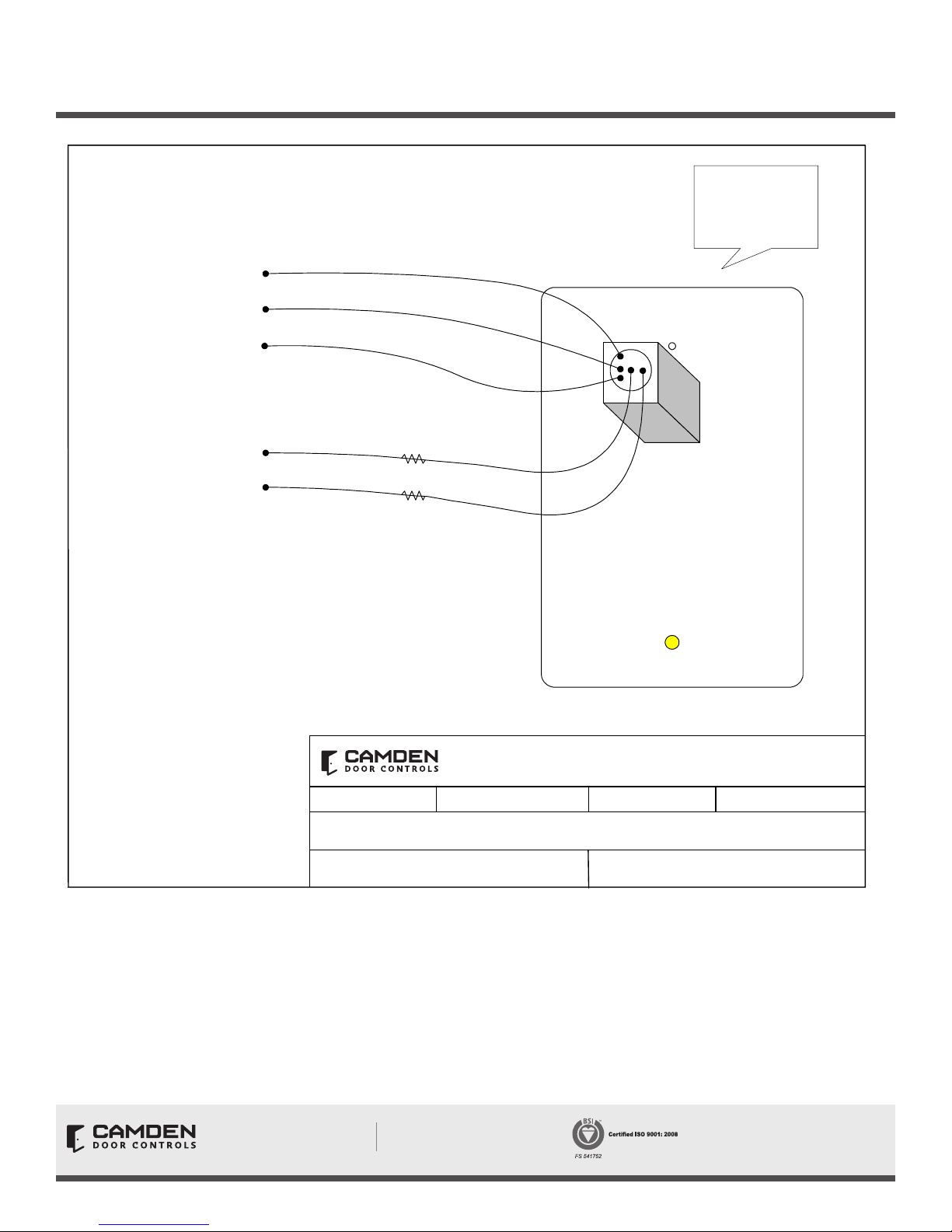
1. The colour coded leads are permanently soldered onto the
back of the switch. The Red & Black wires are for the light.
2. For normally open circuits use the Blue & Green wires.
For normally closed circuits use the Yellow & Green wires.
3. Tuck wiring into box and fasten switch plate using screws
provided (CM-300), or tuck wiring into frame and fasten to
frame using screws provided (CM-310).
Page 1 of 1
Page 2
CM-300 SERIES EXIT SWITCH
INSTALLATION INSTRUCTIONS
Rear View of
CM-300 switch
and Faceplate
Normally
Yellow
Closed
Normally
Blue
Open
Common
Light (-)
Light (+)
NOTE:
LED Replacement
For 12V DC operation, cut off inline-resistor (on Black wire only).
For 24V DC operation, leave inline resistor in place.
Access to LED is obtained by first removing front rectangular lens with
a thin blade screwdriver.
Then, using a pair of needle-nose pliers, carefully pull LED straight out.
Re-installation is reverse of above sequence.
Be sure to line up both pins before pushing LED in.
Green
Black
Red
SCALE: NONE
DRAWING No: DRG-CM300-060503
Opening New Doors to
Innovation, Quality and Support!
Camden Door Controls
DRAWN BY: DGW
CM-300 Series Exit Switch Wiring Diagram
Call: 1.877.226.3369 / 905.366.3377
Visit: www.camdencontrols.com
DATE: 03/18/03
FILENAME:
CM-30 Instructions.doc Pg. 2
5502 Timberlea Blvd.
Mississauga, Ontario
L4W 2T7
REVISED:
File: CM-300 Series
Installation Instructions.indd R3
Revision: 29/10/2018
Part No.: 40-82B039
Page 1 of 2
 Loading...